1
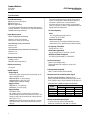
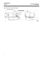
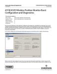
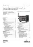
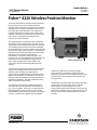
Product Bulletin 4320 Position Monitor 62.3:4320 July 2014 D103286X012 Fisherr 4320 Wireless Position Monitor The Fisher 4320 wireless position monitor eliminates the need for wiring to an on/off pneumatically actuated valve. It provides a precise wireless feedback signal to indicate equipment position with a percent (%) of span plus on/off indication. The 4320 can be used to control and/or monitor valves, slidingstem regulators, displacement and float level sensors, and relief valves. It is designed to be simple to use, compact, and easily mounted. The control portion of the 4320 accepts commands through the wireless network from a control system and provides a pneumatic on/off signal to an actuator. The feedback portion of the instrument periodically reads the position of a measured device and transmits that data over the wireless network. Transmitted data includes the percent of span value, limit switch status indications, valve set point, internal device temperatures, and power module voltage. It also checks for service and configuration instructions from host systems such as distributed control systems (DCS), asset management systems (AMS), and supervisory control and data acquisition (SCADA) systems. The 4320 can be powered by a battery sourced power module, eliminating the need to install wires. This makes it easier to design new applications or implement into retrofit locations. An external power option is also available. The elimination of levers and linkages reduces the number of mounting parts and installation complexity. The autocalibration feature allows consistent valve feedback. The 4320 uses a linkage-less feedback design that eliminates direct contact with the measured device (e.g., valve, regulator, level, louver, or other devices) eliminating physical contact and wear. IEC 62591/ WirelessHARTr communication protocol, operating at 2.4 Ghz, is utilized and is approved for use globally. www.Fisher.com X0535 ON/OFF CONTROL OPTION Instrument calibration and commissioning is performed with a push button and liquid crystal display (LCD) interface. This simplicity eliminates the need for tools or the setting of cams during setup, saving you time. Designed to meet intrinsically safe and nonincendive requirements, this instrument delivers scalable functionality in a small package. Due to the energylimiting nature of the design, this intrinsically safe device is suitable for use in all zone locations. The battery sourced power module option has no cable conduits. Product Bulletin 4320 Position Monitor 62.3:4320 July 2014 D103286X012 Specifications A maximum 40 micrometer particle size in the air system is acceptable. Further filtration down to 5 micrometer particle size is recommended. Lubricant content is not to exceed 1 ppm weight (w/w) or volume (v/v) basis. Condensation in the air supply should be minimized. Available Mountings J J J Quarter-turn rotary-shaft, Sliding-stem, or Linear applications Can also be mounted on other actuators that comply with IEC 60534-6-1, IEC 60534-6-2, VDI/VDE 3845 and NAMUR mounting standards. Air Consumption(1) 4320 At 5.5 bar (80 psig) supply pressure: 0.036 m3/hr (1.27 scfh) Input Measurement Stem Travel (linear movement) Minimum: 2.5 mm (0.10 inch) Maximum: 210 mm (8.25 inches) Pilot Valve Leakage Maximum at 20_C: 8 ml/min (0.0003 scfm/min) Maximum at -20_C: 800 ml/min (0.028 scfm/min) Shaft Rotation (rotary movement) Minimum: 45_ Maximum: 90_ Air Capacity / Flow Rate Supply Pressure: 1.2 Cv Connections (Optional) Supply, Output Pressure, and Vent: 1/4 NPT Wireless Set Point Command IEC 62591 (WirelessHART) 2.4 GHz DSSS Shaft Rotation (rotary movement, arced array) Minimum: 13_ Maximum: 30_ Measurement Output Analog: 0-100% Discrete: on/off switches (2) Local User Interface Liquid Crystal Display (LCD) Two pushbuttons for navigation, setup, and calibration Reference Accuracy 1% of span Communication Protocol On/Off Control Output Signal Pneumatic signal as required by the actuator, up to 95% of supply pressure Minimum Span: 3.1 bar (45 psig) Maximum Span: 7 bar (101 psig) Action: Single or Double Acting Supply Pressure Minimum: 3.1 bar (45 psig) Maximum: 7 bar (101 psig) Supply Medium Air or Natural Gas Air: Supply pressure must be clean, dry air that meets the requirements of ISA Standard 7.0.01. The supply air at the device should have a dew point less than -20_C (-4_F). Natural Gas: Natural gas must be clean, dry, oil-free and noncorrosive. H2s content should not exceed 20 ppm. HART 7 and IEC 62591 (WirelessHART) Maintenance Port Communication Signal Bell 202 Voltage Signaling: 1200 bps binary phase-continuous Frequency-Shift-Keying (1220 Hz mark, 2400 Hz space) superimposed on voltage level Initial Dynamic Variable Assignments (Default) Position Position Position Secondary (SV) Set Point Set Point Switch States Tertiary (TV) Switch States Switch States Cycle Counter Quaternary (QV) Supply Voltage Supply Voltage Supply Voltage DEVICE STRUCTURE Control Snap Control Monitor Wireless Communication Signal 2.4 Ghz, DSSS, IEC 62591 (WirelessHART) Maximum 10 dBm (10 mW) EIRP at 2.46 GHz -continued- 2 Dynamic Variable Assignment Primary (PV) Product Bulletin 4320 Position Monitor 62.3:4320 July 2014 D103286X012 Specifications (continued) Electrical Classification Wireless Classifications Class A digital device, complies with part 15 of the FCC Rules Contains FCC ID: LW2RM2510 Contains IC: 2731A-RM2510 CSA (C/US)— Intrinsically Safe ATEX— Intrinsically Safe IECEx— Intrinsically Safe Contact your Emerson Process Management sales office for classification specific information Electromagnetic Compatibility Meets EN 61326‐1 (First Edition) Immunity—Industrial locations per Table 2 of the EN 61326‐1 standard Emissions—Class A & B ISM equipment rating: Group 1, Class A & B Electrical Housing Type 4X, IP66 & IP67 Vibration Testing Other Classifications/Certifications Meets or exceeds vibration levels specified in ANSI/ISA 75.13.01 1996 (2007): 4 mm peak to peak at 5 Hz, 2 g from 15150 Hz, and 1 g from 150 2000 Hz Customs Union—Russia, Belarus & Kazakhstan INMETRO—National Institute of Metrology, Quality and Technology (Brazil) NEPSI—National Supervision and Inspection Centre for Explosion Protection and Safety of Instrumentation (China) European Directive Information This product complies with the following directives: PESO CCOE—Petroleum and Explosives Safety Organisation - Chief Controller of Explosives (India) ATEX Directive (94/9/EC) Electro Magnetic Compatibility (EMC) (2004/108/EC) Radio and Telecommunications Terminal Equipment Directive (R&TTE) (1999/5/EC) Contact your Emerson Process Management sales office for classification/certification specific information Refer to the Safety Instructions (D103022X012) for the Declaration of Conformity IEC 61010 Compliance Meets Pollution Degree 2 Operating Temperature Limits(2) Monitoring Battery Power: -40 to 85_C (-40 to 185_F) External Power: -40 to 80_C (-40 to 176_F) LCD may not be readable below -20_C (-4_F) Adjustments Zero and Maximum Span through local interface With Pnuematic Output (On/Off Control Option): -20 to 50_C (-4 to 122_F) Dimensions See figure 1, 2, and 3 Temperature Sensitivity 0.06% change per degree C Weight Monitoring: 0.57 kg (1.25 lbs) On/Off Control: 1.6 kg (3.4 lbs) Storage Temperature Limits(2) -40 to 70_C (-40 to 158_F) Power Module Humidity Limits Standard —Lithium (non-rechargeable) 10-95% Non‐Condensing Relative Humidity -continued- 3 Product Bulletin 4320 Position Monitor 62.3:4320 July 2014 D103286X012 Specifications (continued) Power Module Limits Standard— 5 years at update rate of 16 seconds or longer with 3 additional devices communicating through it Extended‐Life— 10 years at update rate of 8 seconds or longer with 3 additional devices communicating through it Shelf life —10 years (radio off) External Power (Optional) 12 - 28 volts DC 100 mA maximum operating current Polarity Insensitive Wire Size— 14-20 gauge Update Rates For position feedback, temperature, and power module voltage—selectable from 1 second to 1 hour; 1s, 2s, 4s, 8s, 16s, 32s, 1 to 60 minutes Note: Sample rate for position feedback is normally the same as the update rate. Construction Material Housing: A03600 low copper aluminum alloy Elastomers: nitrile, fluorosilicone 1. Normal m3/hour - Normal cubic meters per hour at 0_C and 1.01325 bar, absolute. Scfh - Standard cubic feet per hour at 60_F and 14.7 psia. 2. The temperature limits in this document and any applicable standard or code limitation for valve should not be exceeded. 4 Product Bulletin 4320 Position Monitor 62.3:4320 July 2014 D103286X012 Features n Simplicity— The 4320 is easy to use. The linkageless feedback system is easy to install with a magnet array assembled to the valve stem. The 4320 has a local user interface that will allow you to calibrate the instrument. The full text display in the local interface is easy to navigate, in part due to the selection of languages. n Quick Installation—Simply attach the 4320, calibrate and commission to any control system. With the pneumatic output option, only air is needed to automate an on/off valve. No conduit easements or permits are required with the standard or extended life power modules, thus saving time, costs, and effort in documenting cable runs and associated design reviews. Because there is no wiring, implementation times are shortened for device installation, setup, and commissioning. n Energy Efficiency—The optional pneumatic output has zero steady state air consumption. Air generation costs can be reduced. n Minimized Maintenance—The feedback design provides more accurate monitoring and eliminates physical wearout common in traditional valve instruments. This results in less frequent maintenance, repair, and recalibration. Power modules can be easily replaced without losing power to the device, using the “hot swap” feature to maintain network reliability. n Diagnostics—Predefined device, network, and system diagnostics provide details on the health of the device and its ability to communicate. Device diagnostics include whether the device calibration has been completed and power module health. The number of completed cycles is measured for the monitored equipment. Note A cycle is the change from open to closed position or vice versa. This is determined by moving past the trigger point in each direction. n Reliability—The WirelessHART selforganizing mesh network provides the high level of communication reliability required in process control. n Power Options—More than 5 years operation is typical using standard life and extended life power modules. Optional ability to use local 1228 V power in the field. n Security—The WirelessHART self-organizing mesh network includes encryption, authentication, and authorization mechanisms to provide the level of security required in process locations and by the Information Technology (IT) industry. 5 Product Bulletin 62.3:4320 July 2014 Integration Because the 4320 wireless position monitor operates with WirelessHART communications it can be used for incremental monitoring applications. This replaces manual efforts to audit or verify equipment position during normal operations, such as startup and shutdown situations, product changeover, product isolation, and sampling activities. One implementation method can be accomplished using an overlay approach; adding wireless instrumentation on top of existing instrumentation. This preserves the existing infrastructure and enables improved information for operation, reactiveness, maintenance, and safety. A second approach is to replace older limit switches and position transmitters, either because of increased maintenance requirements or dated wiring infrastructure that has become or is believed to become an operational concern. A third approach is to use the 4320 where feedback is not possible with standard wired options. For example, on rotating equipment, where the elimination of wires makes feedback possible. The wireless nature of this device leads to its implementation in a wide range of systems, from programmable logic controllers (PLC), to DCS, AMS, and SCADA systems. System integration for typical in-plant operations is available through the Smart Wireless 1420 Gateway. Principle of Operation The control portion of the 4320 accepts commands through the wireless network from a control system 6 4320 Position Monitor D103286X012 and provides a pneumatic on/off signal to an actuator. The internal electronics periodically reads the position of travel and transmits that data over the wireless network. The device also checks for instructions from host systems like DCS, SCADA and asset management systems. The device “sleeps” until the next reading, enabling longer power module life. The device is still powered up in the sleep mode but operating at ultra-low power consumption levels. Setup/Installation Device setup is typically performed prior to installation and includes setting two network parameters. These parameters are entered using a handheld such as the 475 or 375 Field Communicator. Calibration is performed after installation and requires using the local interface to place the device at the end points of travel range. The device is then ready for commissioning and service. Battery Sourced Power Module Life The 4320 position monitor uses power efficient measures to keep energy consumption to a minimum. However, there is a finite amount of energy within the power module. The life expectancy of the module is affected by two things; 1) the reporting rate, and 2) the number of devices in the network that must communicate through the 4320 position monitor. Typical on/off applications will operate effectively at one minute reporting periods. Product Bulletin 4320 Position Monitor 62.3:4320 July 2014 D103286X012 Ordering Information When ordering, specify: 1. Position monitor control For linear movement, indicate travel length: n 7 mm (1/4 inch), n 19 mm (3/4 inch), n 25 mm (1 inch), n 38 mm (1-1/2 inch), n Monitoring n 50 mm (2 inch), n On/off control option n 100 mm (4 inch), or 2. Power source n Battery sourced power module n External power option 3. Mounting requirements Feedback sensor and mounting brackets are part of the mounting. n 210 mm (8-1/4 inch) strokes Note As a general rule, do not use less than 50% of the magnet assembly for full travel measurement. Performance will decrease as the assembly is increasingly subranged. Contact your Emerson Process Management sales office if longer travel lengths are required. For rotary movement indicate if mounting requirements are: n 90_ NAMUR, n 90_ ISO mounting, or Note Contact your Emerson Process Management sales office if mounting on non-Emerson valves is required. n 30_ for special applications 7 Product Bulletin 4320 Position Monitor 62.3:4320 July 2014 D103286X012 Figure 1. Dimensions 172 (6.79) 18.8 (0.74) 89.8 (3.54) 136.7 (5.38) 17 (0.67) 39.9 (1.57) 50 (1.97) 11 (0.44) 51.1 (2.01) 19.9 (0.78) 67 (2.64) 128.9 (5.08) 19.9 (0.78) 11 (0.44) ANTENNA SHOWN VERTICAL 69.4 (2.73) 6X M6 - 1 13 mm MAXIMUM ALLOWABLE THREAD ENGAGEMENT 91.7 (3.61) 50 (1.97) 17.68 (0.70) 35.7 (1.40) 17.68 (0.70) 35.36 (1.39) 35.7 (1.40) 46.72 (1.84) GE41356-C 8 35.36 (1.39) 46.72 (1.84) ANTENNA SHOWN HORIZONTAL mm (INCH) Product Bulletin 4320 Position Monitor 62.3:4320 July 2014 D103286X012 Figure 2. Dimensions with On/Off Control Option 197.3 (7.77) 89.8 (3.54) 136.7 (5.38) 18.8 (0.74) 41.8 (1.65) 50 (1.97) 11 (0.44) 1/4-18 NPT SUPPLY 51.1 (2.01) 39.9 (1.57) 19.9 (0.78) 67 (2.64) 128.9 (5.08) 19.9 (0.78) 6.6 (0.26) 97.6 (3.84) 97.6 (3.84) 11 (0.44) ANTENNA SHOWN VERTICAL 69.4 (2.73) 6X M6 - 1 13 mm MAXIMUM ALLOWABLE THREAD ENGAGEMENT 91.7 (3.61) 50 (1.97) 17.68 (0.70) 35.7 (1.40) 10.7 (0.42) 17.68 (0.70) 35.36 (1.39) 10.8 (0.43) 2X 1/4-18 NPT TO ACTUATOR GE59669 35.7 (1.40) 46.72 (1.84) 35.36 (1.39) 46.72 (1.84) ANTENNA SHOWN HORIZONTAL mm (INCH) 9 Product Bulletin 4320 Position Monitor 62.3:4320 July 2014 D103286X012 Figure 3. Dimensions—External Power Option ON/OFF CONTROL OPTION 42 (1.66) M20 X 1.5 OR 1/2-14 NPT CONDUIT CONNECTION 60 (2.36) 20 (0.79) GE59678 10 mm (INCH) 4320 Position Monitor D103286X012 Product Bulletin 62.3:4320 July 2014 11 Product Bulletin 62.3:4320 July 2014 4320 Position Monitor D103286X012 For additional information on the 4320 wireless position monitor, scan or click the QR code Neither Emerson, Emerson Process Management, nor any of their affiliated entities assumes responsibility for the selection, use or maintenance of any product. Responsibility for proper selection, use, and maintenance of any product remains solely with the purchaser and end user. Fisher is a mark owned by one of the companies in the Emerson Process Management business unit of Emerson Electric Co. Emerson Process Management, Emerson, and the Emerson logo are trademarks and service marks of Emerson Electric Co. HART and WirelessHART are marks owned by the HART Communication Foundation. All other marks are the property of their respective owners. The contents of this publication are presented for informational purposes only, and while every effort has been made to ensure their accuracy, they are not to be construed as warranties or guarantees, express or implied, regarding the products or services described herein or their use or applicability. All sales are governed by our terms and conditions, which are available upon request. We reserve the right to modify or improve the designs or specifications of such products at any time without notice. Emerson Process Management Marshalltown, Iowa 50158 USA Sorocaba, 18087 Brazil Chatham, Kent ME4 4QZ UK Dubai, United Arab Emirates Singapore 128461 Singapore www.Fisher.com E 122009, 2014 Fisher Controls International LLC. All rights reserved.