1
TX700-148
TX700-132
TX700-64
TX700-32
TX700-16
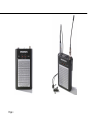
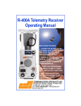
700 SERIES-MULTI-FREQUENCY
POCKET TRANSMITTER
Page 2
INSTRUCTION MANUAL
Covers the following models:
700 SERIES : TX700-148, TX700-132,
TX700-64, TX700-32,TX700-16
Part No IMTX700-1.3
Page 3
Page 4
Contents
General description ...............................................................7
Main Features ........................................................................8
Unique Micron Companding System .....................................11
Control Panel ........................................................................12
Switch panel .........................................................................13
Transmitter Powering ............................................................16
Battery Test and Transmitted Warning..................................17
Automatic Level Control System ...........................................18
Operating Instructions ..........................................................19
How to get the best from the MICRON .................................21
Interference ..........................................................................23
Technical Data ......................................................................25
Antenna Data ........................................................................28
Transmitter Input Connectors ................................................29
Transmitter Cables ...............................................................30
Cable Ended Microphones ...................................................36
Distributors ..................................................................... Appendix
Page 5
Page 6
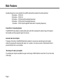
Main Features
The Micron TX700’s sophisticated design is based around a low-noise VCO, with digitally controlled PLL circuit,
producing the highest possible quality of transmitted signal. The lightweight, yet rugged aluminium extrusion case
provides strength and durability, and is designed to withstand the heavy demands of location use, while being
comfortable to wear - ideal for situations where concealment is important. The unique battery compartment design
enables fast and easy battery replacement.
Adjustment of the audio level is straightforward, with the modulation level control easily accessible through the
TX700’s top panel, where peak-reading LEDs (-10 and 0dB) indicate the audio level, allowing repeatable levels to be
set. The TX700 includes a soft audio limiting circuit, with the threshold user-adjustable to give a wide range of
operation from fully automatic to no limiting action. The advanced design enables the limiter to be used as an
automatic level control, without the pumping effect usually associated with audio AGC, and it can also be used as a
‘distortionless’ emergency limiter to prevent over-modulation.
Additional front-end protection is provided by a bass-cut switch, which may be used to reduce wind noise and
counteract close-microphone effects. The use of dedicated audio input cables enables the transmitter to accept line
and mic level signals, and to power a wide variety of microphone types. The TX700 is equipped with a battery
condition indicator on the top panel, and also transmits an inaudible ‘low battery voltage’ warning signal, which
activates a visual indication on the matching Micron receiver.
The MICRON POCKET TRANSMITTER is available in 4 different models: Model Number:
Number of Channels:
Frequency Range:
TX700 -148
100
470-865MHz
TX700 - 132
100
470-865MHz
TX700 - 64
64
470-865MHz
TX700 - 32
32
470-865MHz
TX700 - 16
16
173-217MHz
Switchable Frequency
Page 7
Main Features
Operating frequencies can be selected from two BCD coded switches located in the switch panel label.
100 positions – TX700-148
100 positions – TX700-132
100 positions – TX700-64 (with 64 operating frequencies)
100 positions – TX700-32 (with 32 operating frequencies
16 positions – TX700-16 (with single BCD coded switch 16 operating frequencies)
Unique Micron Companding System
The MICRON 700 series feature a double ended system which first compresses the dynamic range of the signal in
the transmitter, and then expands it again in the receiver.
Automatic Gain Control Option
The design of the limiter in the MICRON transmitter enables it to be used as an automatic gain control system
without the pumping effect associated with audio A.G.C. systems. It can also be used as a 'distortionless' limiter to
prevent distortion due to over modulation.
'Overload proof' audio input amplifier
The variable gain microphone amplifier has a gain control range of 40dB. Distortion is less than 0.3% over the whole
of this range.
Page 8
Main Features
L.E.D. Volume Indicator
One problem associated with radio microphones is the setting of the modulation level. As with tape recording, too
low a setting results in a poor signal to noise ratio, too high a setting causes distortion. A common practice is to
adjust the audio gain of the transmitter until distortion is heard and then 'back off a bit'. The MICRON transmitter is
fitted with a simple L.E.D. volume indicator (‘0’ and ‘-10’) to allow the modulation level to be set quickly and
accurately, without having to monitor the receiver output.
Multiple Input microphone socket
The 6 way Lemo connector provides:
1. A high sensitivity input for dynamic and condenser microphones (with suitable input cables).
2. Direct powering connection for electret microphones (+ve and –ve bias).
3. Powering for 12V 'T' powered condenser microphones (with suitable input cables).
4. Powering for 12V 'Phantom' powered condenser microphones (with suitable input cables).
5. Powering for 48V 'Phantom' powered condenser microphones with Micron P48 in-line dc booster.
6. Line input capability (with suitable input cables).
7. External powering for transmitter (with suitable input cables).
Page 9
Main Features
Automatic Warning of Transmitter battery failure
The battery warning system transmits an inaudible signal when the transmitter batteries are reaching the end of their
life, causing LED's on the receiver to flash at a slow but steady rate. This gives the operator a warning period before
the batteries must be changed. By keeping a continuous check on the transmitter batteries, the warning system
provides protection against batteries, which appear to be fresh but fail unexpectedly after a short period of use.
Ruggedness
The lightweight aluminum extrusion transmitter case is strong by virtue of its shape. The shell strength is reinforced
by the front and back panel and electronic circuitry is separated by the battery compartment.
Electronic Reliability
Exhaustive test procedures account for roughly half the manufacturing cost of a MICRON. The transmitters and
receivers are constructed from pre-aligned electronic modules. The highest risk of component failure is usually early
in its working life. The object of the lengthy test routine is to force the potential faults to occur before the unit leaves
the factory.
Every module is tested and heat cycled. If the modules perform correctly, they are assembled into complete
transmitters and receivers and given a 100-hour burn in, certain critical parts are given a further 100-hour reliability
test. After alignment, every transmitter and receiver is checked for correct performance at 0oC, 25oC and 50oC,
after a further complete test a MICRON is passed to leave the factory.
Page 10
Unique Micron Companding System
The TX700 Series body-worn transmitters feature the Unique Micron Companding System. This double-ended
system first compresses the dynamic range in the transmitter and then expands it again at the receiver.
The MICRON Companding System is a high performance symmetrical design. It offers many significant advantages
over more conventional compandor techniques. These operate in parallel to supply a level-dependent, variable rate
compressed signal, which is expanded in the receiver by a matching pair of circuits to complete the Companding
processing. Graded pre-emphasis is used in the gain control paths, in order to eliminate low frequency modulation
effects. When compared to standard 2:1 companding methods, this degree of sophistication provides the user with
greatly improved operational performance and sound quality.
Because the signal to noise performance is so improved, the operating distance between transmitter and receiver
antenna can be much greater; what were previously unusable weak signal areas are now usable. In outside
broadcasts, sound and camera can now operate in synchronization over longer distances and the full potential of
20:1 zoom lenses can be realized.
Similarly, there is greater immunity from interference; low-level interference signals are further depressed and the
difference between wanted and unwanted signals is expanded. Impulsive interference such as switch clicks and
motor hash greatly reduced.
Multi-channel performance, which previously suffered from low level interference from intermodulating signals
(birdies), is significantly improved.
MICRON 700 Series transmitters are compatible with the SDR 700 series receivers
* 700 Series are not compatible with 100 and 500 Series.
Page 11
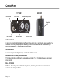
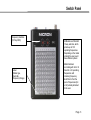
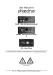
Control Panel
TOP VIEW
Antenna Socket
ON/OFF Switch
SIDE VIEW
Modulation/Battery Indicator
Phase Switch
Bass Cut Switch
Set Level Control
Audio Input Socket
Audio Input Socket
A 6 pin Lemo connector with gold plated pins. The microphone-input cable is connected by a push-pull action. The
transmitter offers many audio input options depending on the pin configuration selected. The variations in pin
selection is detailed under 'Transmitter cable connection data'.
Set Level Control
A screwdriver operated audio gain control, used to set the modulation level.
Modulation Level and Battery Status Indicators
The 2 light emitting diodes (LED's) act as a simple volume indicator. The ‘-10’ light also doubles up as a battery
status indicator.
Bass - Cut Switch
The Bass – Cut switch provides added front-end protection, where it may be used to reduce wind noise and
counteract close microphone effects.
Page 12
Control Panel
ON / OFF Switch
Slide Switch to turn the TX ‘on’ or ‘off’. Flash mounted to prevent accidental operation.
Antenna Socket
A SMA 50 Ohm coaxial socket. The antenna can be connected by a screw-on action.
Phase Switch
A flush mounted phase change slide switch for the signal input.
Page 13
Switch Panel
Frequency change switch (TX700-148/TX700-132, TX700-64/TX700-32)
Two BCD coded switches give the user a choice of up to 100 operating frequencies (depending upon the model).
There are 4 models available:
Model
TX700-148
Switch Combination
10 x 10
Number of Channels
100
Switch Bandwidth
48 MHz
TX700-132
10 x 10
100
32 MHz
TX700-64
10 x 10
64
24 MHz
TX700-32
10 x 10
32
14 MHz
TX700-16
1 x 16
16
Up to 24MHz
The frequencies are shown on the serial no label.
Serial No Label
Gives information on:
1) Model type.
2) Serial No.
3) Switchable frequencies in MHz.
NB. The arrow on the switch is used as indicator
Page 14
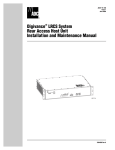
Switch Panel
Frequency Switches
(10 Way BCD)
Label
(Model type,
Serial No.,
Frequency Range)
All Models are fitted with
10 way switches, which
provide up to 100
operating frequencies.
Depending on the model
ordered the user would
have different options:
Model Numbers
concluding with 64 or 32
have 64 or 32 operating
frequencies with
remaining frequency
slots filled in from the
pool of frequencies (64
or 32) already allocated
to the user
Page 15
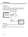
Transmitter Power
1) Internal 9V Battery
Alkaline battery types are recommended.
As the transmitter RF driver stage is stabilized, the output power remains virtually constant as the battery voltage
falls. There will be no loss of range or performance as the battery volts fall from 9 to 6 volts. The transmitter batterywarning signal starts when the supply voltage has fallen to 6.5 volts (approx.)
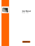
Opening the battery compartment
The battery compartment is
opened by pressing the button on
the back of the unit on the front
there is slot for the 9V battery to
fit into.
The battery can be easily
released with the aid of
the thumb cut-out.
2) External Powering
It is recommended that external power be only applied via a MICRON TLP lead as this lead includes a 9V voltage
regulator and dc filtering.
NOTE: Using a transmitter supply greater than 9 volts will not increase the output power and may cause damage to
the transmitter.
Page 16
Battery Test and Transmitted Warning
Alkaline manganese batteries are the most suitable because of their long life and reliability. They have a long shelf
life and can be relied on to yield their full rated capacity. The conventional 9-volt transistor radio battery is NOT
recommended.
Lithium and Mercury batteries have a high capacity and long shelf life but, as they maintain an almost constant
voltage in use and then fail suddenly at the end of their life, the transmitter alarm system can only give a brief
warning of impending failure.
Battery Life; 6 to 7 hours continuous
Figures are based on a 30mW transmitter @ 20oC
Battery data is approximate since battery capacity varies with age and ambient temperature, and transmitter
consumption varies with antenna position.
Battery test
With an input plug connected the –10dB LED indicator also operates as a battery voltage indicator.
-10 LED > 6.5V: No Audio – LED not ‘ON’
: With Audio – LED ‘ON’ GREEN
'-10' LED <6.5V: No Audio – LED ‘ON’ RED
: With Audio – LED ‘ON’ AMBER
Transmitted battery warning
A pair of lamps on the LED display of the matching MICRON receiver flash regularly 2-3 times per second when the
TX battery volts fall to 6.5 Volts. The TX batteries should be changed at the first opportunity.
TX Battery Warning Limits
If the TX is already in use, continue until convenient to change, but within the limit of 20 to 30 minutes.
Page 17
Automatic Level Control System
The level control is, in principle, a peak limiter. Its function is to prevent distortion due to overmodulation. Because of
the definitive design, it can be used as an audio AGC system with characteristics much improved over the 'automatic
record' facility of most tape recorders. The center of the system is a voltage controlled variable gain amplifier with a
control range of 40dB.
The Automatic Level Control (ALC) system can be set so that it operates only in an emergency ('Normal' mode) or
so that it adjusts the gain to suit the user's voice level ('Automatic' mode) or so that it never operates at all, except in
an extreme emergency ('Low modulation' mode).
When used in the 'Automatic' mode, the control system sets the audio gain so that the average speech level is about
9dB below peak modulation level. This leaves headroom for the short sharp transients, which occur frequently in
speech patterns. Having set the gain, the short transients pass without distortion and without further need to change
the gain.
Page 18
Operating Instructions
Receiver (RX) setting up - (SDR770 series)
Set up the receiver referring to the relevant instruction manual
Transmitter (TX) Setting Up
•
Fit a PP3 9V battery
•
Connect provided TX antenna (flexible SMA antenna)
•
Set your TX frequency same as RX
•
Switch on TX (by connecting microphone cable to 6-way multi-way socket)
•
Check TX battery status LED, if RED (with no audio to the microphone) replace TX battery with a new one
•
Check RX RSSI indicator – all lights should lit
•
Adjust SET LEVEL gain control, while performer speaks at correct level
‘-10’ lamp flashes regularly and ‘0’ lamp flashes occasionally
(For any electret microphones the setting will be ‘Level 4 or 5’)
Interference Check
Switch off TX - by disconnecting microphone cable.
Observe signal strength indicator and listen for possible interfering signals from other transmitters (slight flickering of
lowest lamps is acceptable.)
Reconnect microphone cable and adjust SET LEVEL control by one of the following methods
.
Page 19
Operating Instructions
'NORMAL'
This method suits most situations when there is time for a rehearsal and gives the optimum balance between
dynamic range and signal to noise ratio. Unless an unexpectedly loud sound occurs, the limiter will not operate.
Adjust SET LEVEL control, while performer speaks at correct level, so that -10 lamp flashes regularly and '0'
lamp flashes occasionally.
TX is now ready for use.
'FULLY AUTOMATIC'
This procedure is for News reporting, interviews and other situations where there is no opportunity for rehearsal with
the performer. The objective is to preset the audio gain slightly too high and allow the limiter to control the level.
Speak in an average to quiet voice with the microphone in a realistic position, while adjusting the SET LEVEL
control, so the '0' lamp flashes regularly.
TX is now ready for use.
LOW MODULATION LEVEL
This procedure is for those situations where the dynamic balance of the dialogue must not be altered at all, such as
Theatre Musicals or for stereo productions. In this mode the automatic leveling threshold is set to be above the
highest expected input level.
Adjust SET LEVEL control, while performer speaks at normal level, so the -10 lamp flashes occasionally and the
'0' lamp never flashes at all. (For Musicals, it may be preferable to adjust the SET LEVEL control on the loudest
passage so the '0' does not flash).
TX is now ready for use.
Page 20
How To Get The Best From a MICRON
Transmitter
The end of the antenna is most sensitive to body absorption so keep away from the wearer's body if at all possible.
Keep the TX antenna reasonably straight and away from the microphone lead. Avoid coiling the antenna, especially
near the transmitter case.
Receiver
Whenever possible use a MICRON diversity receiver to ensure optimum operating reliability. A standard nondiversity receiver will also give good results if the following suggestions are applied.
Antenna
Raise the antenna as high as possible and keep it away from metal objects. Place the antenna as close to the
'action' as possible. Put the receiver as near to its antenna as possible, i.e. use long audio cables rather than long
RF cables. A full sized half wave dipole will give a slightly higher output than the short helical antenna, the increase
being a few dB. A properly designed multi element directional antenna will give greater improvement because of its
gain. It is also a useful means of rejecting a known source of interference if it can be placed with its 'back' to the
interfering source.
Walk test
Whenever possible during rehearsal move the transmitter through all the positions in which it is likely to operate
during the actual performance. Look for possible dead spots by observing the signal strength indicated on the
receiver. If the top lamp goes out during the walkthrough, it is a warning that the signal level has fallen to a low level
and that the background noise could possibly rise unacceptably. If possible move the receiving antenna and repeat
the test until the lamps stay on throughout the walk. As it is difficult to simulate precisely the conditions, which will
exist during the actual performance, it is more satisfactory to operate with a safety margin.
Page 21
How To Get The Best From a MICRON
Safety margin - [Only necessary when the full dynamic range of the system is being utilized]
Reduce the receiver sensitivity by fitting a 50 Ohm 10dB attenuator between the antenna and the receiver. Repeat
the walk about test and move the receiving antenna as necessary to keep the top lamp on. When the attenuator is
removed a safety margin of 10dB has been created. The received signal can fall by 10dB during the performance
without causing an increase in background noise.
For extreme range
For large area coverage a diversity system should be used.
For golf tournaments and other long-range events, use high gain receiving antennas mounted on tall poles or masts.
Where appropriate use a remote transmitter antenna as high as possible. Use thin low loss 50-Ohm coaxial cable to
connect between the transmitter and its antenna.
Public address, fold back and sound reinforcement applications
When using a Micron together with a loudspeaker system, it is important to make the setting up adjustments in the
correct sequence to avoid the danger of acoustic feedback during quiet pauses.
1. Connect up the Micron and adjust the SET LEVEL control by the 'Low modulation' procedure.
2. Walk through the positions in which the Micron will be used and adjust the public address amplifier gain as
necessary to avoid 'howl round'.
Note. If the microphone is static then a cardioid type is preferable, but if the microphone is to be moved around
then an omni type should be used.
Page 22
Interference
There are many possible sources of interference. Examples are: Other transmitters on the same frequency,
harmonics of lower frequency transmissions, intermodulation products from two other incompatible transmitters (see
"Multichannel Operation") man made static from electrical machinery, motor vehicles, and RF from electronic
instruments such as TV sets, digital displays, pocket calculators, mobile phones and the like.
Interfering signals can cause an apparent loss of range. Before suspecting a defect in the MICRON check the
system in another location, which is free from interference.
When checking during rehearsal, ensure that all potential sources of interference are switched on and in position
e.g. TV cameras, PCs, motor generators, arc lights, switchgear, TV monitors, HMI lighting drive units. Note:
Unterminated TV video cables are a particular hazard.
DIVERSITY - If a diversity system is being used, make sure that ALL antennas are spaced well away from possible
sources of interference. To check this, disconnect all antennas and then connect one antenna at a time and make
sure each one is free from local interference.
To improve the situation as far as possible, take the following precautions:
MAKE THE INTERFERING SIGNAL AS WEAK AS POSSIBLE at the receiving antenna:
Switch off the transmitter. Try to identify the source of interference and move the receiving antenna away from it. If
the interference is continuous use the signal strength indicator on the receiver to find a 'weak signal' zone in which to
place the antenna. For a distant interfering signal, moving the antenna may not weaken the received signal. In this
situation a directional antenna with its 'back' to the interfering source, could help. The addition of an earth shield
'behind' the antenna may also help. Rotate the antenna to change the polarization.
MAKE THE WANTED SIGNAL AS STRONG AS POSSIBLE to swamp the interference:
Place the receiving antenna as close as possible to the transmitter. One possibility is to use a directional antenna,
mounted on a microphone boom, and to follow the action. If the antenna has to be fixed and the acting area is large,
use the 'safety margin walkabout test' to find the best site for the antenna.
KEEP THE AUDIO MODULATION LEVEL AS HIGH AS POSSIBLE to give the best signal to noise ratio.
(Noise in this case means a twittering type of sound 'birdies' from the interfering signal). With the Companding
system, interfering signals are held down in quiet passages but rely on the masking effect during loud passages.
Page 23
Interference
Under severe interference or under weak signal conditions, sudden large audio input level changes can produce a
short period of increased background noise. In this situation the wanted signal strength should be increased to
prevent this happening.
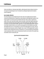
MULTICHANNEL OPERATION
If two radio microphones are used simultaneously at the same location, their operating frequencies should be
chosen with care. Multichannel sets of frequencies have been calculated by Audio Engineering for operation in most
frequency bands. The use of these sets is recommended and should be chosen (in whole or in part) whenever
possible. When any two mobile radio transmitters operate close together, unwanted intermodulation signals will be
produced due to interaction between the transmitters. The closer the transmitters are together and the closer they
are in frequency, the stronger the intermodulation signals will be. If the intermodulation signals fall within the band of
a third channel, interference effects can occur when the received signal from the third transmitter is weak. Similar
intermodulation effects can occur in the input stage of a receiver if the unwanted signals are very strong. There are
many situations where frequencies, which are incompatible, have to be used. The following precautions may help to
minimize the problems. Separate all the receivers (or the antennas). Try to avoid producing strong unwanted signals
in each receiving antenna. Site the receivers (or the antennas) to favour their own channels. As far as possible, keep
all transmitters at least 0.5 metres (20ins) apart.
Typical Transmitter Intermodulation Products
Page 24
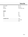
Technical Data
Except where stated, data applies to all MICRON 700 Series transmitters, although there may be minor variations for
some countries.
RF TRANSMISSION SYSTEM
Carrier frequency (to order) ..................................................................................... 173-865MHz
Number of frequencies up to 100
Switching range .................................................................................................... up to 48 MHz
Modulation system................................................................................................... F3 EGN
Maximum Deviation ................................................................................................. 75kHz
Reference Deviation ................................................................................................ 40kHz
RF Output (erp) ....................................................................................................... 50mW
AUDIO
System S/N Ratio .................................................................................................... >100dB
Frequency Response .............................................................................................. 80Hz to 20kHz ±1dB (nom.)
Distortion (@ ref. Deviation level)............................................................................ 1kHz tone <0.3% THD
1kHz tone @ -10dB:0.1%THD(typ)
Page 25
Technical Data
BASS CUT
Fixed Bass Cut: -5dB at 50 Hz
(nom.) Additional 6dB cut at 60Hz
ON / OFF
Flush Mounted Slide Switch
LEVEL CONTROL
Manual pre-set, 40dB in 8 steps
VOLUME LED INDICATORS
‘0’ light at ALC threshold
‘-10’ light at 10dB below ALC
threshold (ALC system allows short
transients to pass up to +6dB)
FREQUENCY CONTROL
Screwdriver pre-set
BATTERY CONDITION INDICATOR (-10dB LED)
LED at <6.5V
TX LOW BATTERY INDICATOR
Signal transmitted at <6.5V
PHASE CONTROL
Phase positions 1 & 2
BATTERY TYPE
IEC 6LR61 (MN1604) PP3 size
9V (Alkaline or Ni Cd)
Page 26
Technical Data
Current consumption
65mA ± 10%
Battery Life
Approx. 6 hours
External Power
7.5 to 16V dc (with ‘TP’ cables)
DIMENSIONS
Width
63mm
Depth
22mm
Height
82mm
Weight
110 grams
ACCESSORIES SUPPLIED ................................................................................... Antenna
................................................................................................................................. Instruction manual
................................................................................................................................. Belt clip
Page 27
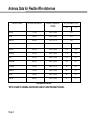
Antenna Data for Flexible Wire Antennae
COLOUR CODE
CENTRE FREQUENCY
USABLE FREQUENCY
RANGE
ACTIVE LENGTH (mm)
RX
TX
BLACK
177.00
169.0 - 186.0
*417
BLUE
196.00
186.0 - 206.0
*376
GREEN
204.00
191.0 - 217.0
*362
BLACK
500.00
470.0 - 530.0
134
129
BROWN
550.00
520.0 - 580.0
115
110
RED
570.00
554.0 - 615.0
112
107
ORANGE
660.00
630.0 - 692.0
103
93
YELLOW
730.00
698.0 - 757.0
95
85
GREEN
767.00
726.0 - 792.0
88
78
BLUE
788.00
764.0 - 850.0
86
76
WHITE
846.00
780.0 - 890.0
81
71
FREQUENCIES IN MHz
*NOTE: RX AND TX ANTENNA LENGTHS ARE SAME IN THESE FREQUENCY RANGES.
Page 28
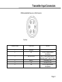
Transmitter Input Connectors
PCB Mounted Multi-Way Lemo or ODU Connector.
Top View
CONNECTIONS
FUNCTION
1
2
Mic input
M-
3
BATT/EXTPWR
4
5
6
Battery 0V
M+
NOTES
-5V out for negative biased
microphones
BATT+ Volts to power P48 or to
externally power TX with TLP cable
Link Battery - and
0V to turn TX ‘ON’
+9V out for positive biased
microphones
Page 29
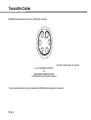
Transmitter Cables
MICRON numbering scheme for Lemo or ODU cable connector
View from soldering side of connector
Lemo FGG.OB.306 CLAD31Z
Or
ODU S20BOC-TO6MCCO-30GP
6 Pin Microphone Input Cable Connector
The pin numbers indicate the wiring standard set by MICRON and all cables in this manual.
Page 30
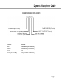
Dynamic Microphone Cable
TRANSMITTER CABLE CODING EXAMPLE
YELLOW
WHITE
GREEN
BLACK
BLACK (SPLIT CABLE)
DYNAMIC
CONDENSER (A/B POWERED)
CONDENSER (12V PHANTOM)
LINE
LINE (EXTERNAL POWERING)
Page 31
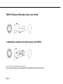
TDN15CF6 (Dynamic Microphone Cable, Code Yellow)
T12MICRON6 (Condenser AB Powering Cable, Code White)
View of LEMO from soldering side of connector.
The pin numbers indicate the wiring standard set by MICRON and all cables in this manual.
Page 32
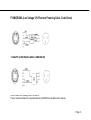
P12MICRON6 (Low Voltage 12V Phantom Powering Cable, Code Green)
TL20CF6 (Line Input Cable, Code Black)
View of LEMO from soldering side of connector.
The pin numbers indicate the wiring standard set by MICRON and all cables in this manual.
Page 33
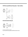
TLPO7CF6 (Line Input With External Powering Cable – Y Cable, Code Black)
P48 MICRON (Phantom Powering 48V)
View of LEMO from soldering side of connector.
The pin numbers indicate the wiring standard set by MICRON and all cables in this manual.
Page 34
2TLPO7CF6 (Double Line Input with External Powering Cable, Code Red/Blue)
View of LEMO from soldering side of connector.
The pin numbers indicate the wiring standard set by MICRON and all cables in this manual.
Page 35
Cable Ended Microphones
View of LEMO from soldering side of connector.
The pin numbers indicate the wiring standard set by MICRON and all cables in this manual.
Page 36
Cable Ended Microphones
View of LEMO from soldering side of connector.
The pin numbers indicate the wiring standard set by MICRON and all cables in this manual.
Page 37
Page 38
AUDIO ENGINEERING LIMITED, MICRON HOUSE, 3 NEW ROAD, LONDON N8 8TA
Telephone: +44 (0) 20 8341 3500
Fax: +44 (0) 20 8341 5100