1
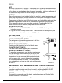
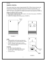
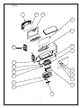
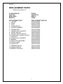
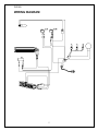
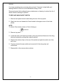
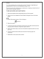
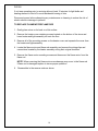
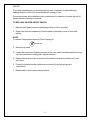
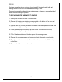
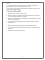
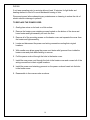
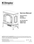
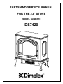
PARTS AND SERVICE MANUAL
FOR THE 23” STOVE
MODEL NUMBER:
DS7420
TABLE OF CONTENTS
OPERATION
PAGE 1
PARTS DRAWING
PAGE 3
PARTS LIST
PAGE 4
WIRING DIAGRAM
PAGE 5
LIGHT BULB REPLACEMENT
PAGE 6
MAIN ON/OFF SWITCH REPLACEMENT
PAGE 8
LIGHT DIMMER SWITCH REPLACEMENT
PAGE 9
FLAME MOTOR/FLAME ROD REPLACEMENT
PAGE 10
HEATER ON/OFF SWITCH REPLACEMENT
PAGE 11
HEATER THERMOSTAT CONTROL REPLACEMENT
PAGE 12
HEATER ASSEMBLY REPLACEMENT
PAGE 13
POWER CORD REPLACEMENT
PAGE 14
DS7420
NOTE
A 15amp, 120 volt circuit is required. A dedicated circuit is preferred but not essential in
all cases. A dedicated circuit will be required if, after installation, the circuit breaker trips
or fuse blows on a regular basis when the heater is operating. Additional appliances on
the same circuit may exceed the current rating of the circuit breaker.
WARNING
Ensure the power cord is not installed so that it is pinched or against a sharp edge and
ensure that the power cord is stored or secured to avoid tripping or snagging to reduce
the risk of fire, electric shock or injury to persons.
Construction and electrical outlet wiring must comply with local building codes and other
applicable regulations to reduce the risk of fire, electric shock and injury to persons.
Do not attempt to wire your own new outlets or circuits. To reduce the risk of fire,
electric shock or injury to persons, always use a licensed electrician.
STOVE INSTALLATION
1. Make sure the units MAIN ON/OFF switch is switched OFF (refer to operating
instruction section).
2. Plug the unit into a 15Amp/120volt outlet. If the cord does not reach, you may use
an extension cord rated for a minimum of 1875 watts.
OPERATION
To access the controls, go to the back of the stove.
A. MAIN POWER ON/OFF SWITCH
The main power on/off switch supplies power to all stove
functions (heater & flame).
B. TOP LIGHT ON/OFF SWITCH
Controls the light intensity of the log bed display area.
A
B
C
C. HEATER ON/OFF SWITCH
The heater on off switch supplies power to the heater.
D. HEATER THERMOSTAT CONTROL
To adjust the temperature to your individual requirements,
turn the thermostat control clockwise all the way to turn
on the heater. When the room reaches the desired
temperature, turn the thermostat knob counter clockwise
until you hear a click. Leave in this position to maintain
the room temperature at this setting. For additional heat,
turn clockwise until you hear the click again and the heater
will turn on.
D
FIGURE 1
RESETTING THE TEMPERATURE CUTOFF SWITCH
Should the heater overheat, an automatic cut out will turn the heater off and it will not
come back on without being reset. It can be reset by switching the MAIN ON/OFF
SWITCH to OFF and waiting 5 minutes before switching the unit back on.
CAUTION
If you need to continuously reset the heater, unplug the unit and call Dimplex North
America Limited at 1-800-668-6663.
1
DS7420
REMOTE CONTROL
The remote control has a range of approximately 50ft. (15.25m) it does not have to be
pointed at the fireplace and can pass through most obstacles (including walls). It is
supplied with one of 243 independent frequencies to prevent interference with other
units. The frequency designation is indicated on the back of the transmitter (FIGURE 3)
REMOTE CONTROL INSTALLATION
1. Plug fireplace cordset into the outlet located on the side of the receiver. (FIGURE 2)
2. Plug receiver into the wall outlet.
3. Install a 9 volt battery into the transmitter. (FIGURE 3)
Receiver
Outlet
FIGURE 2
NOTE
• Fireplace MAIN on/off switch must be in the
ON position prior to using the Remote Control.
• ON/OFF Remote Control may be used to
control most other electrical devices including
T.V.’s, stereos and lamps.
CAUTION
• For indoor use in dry areas only
• For use on electrical devices with 15 amp
resistive load or 1/3 HP inductive load
• 120 volt AC only
OPEN
Frequency
Code
Battery
Cover
FIGURE 3
2
DS7420
2
15
10
13
1
14
19
7
3
4
10
16
9
17
8
6
5
18
11
3
DS7420
REPLACEMENT PARTS
STOVE, ELECTRIC 23"
CATALOGUE NO.
PART NO.
MOD LEVEL:
MADE IN:
DS7420
6900470759
MOD. D
CHINA
REPLACEMENT PART
1. LOG SET
2. DOOR
3. FOOT
4. FLAME MOTOR
5. HEATER ASSEMBLY
6. THERMOSTAT
7. LOWER LIGHT HARNESS
8. ON/OFF SWITCH
9. HEATER ON/OFF SWITCH
10. UPPER LIGHT ON/OFF SWITCH
11. CORD SET
12. UPPER LIGHT HARNESS
13. MIRROR
14. REFLECTOR ASSEMBLY
15. FRONT GLASS
16. CAPACITOR
17. TERMINAL BLOCK
18. KNOB CONTROL
19. REMOTE CONTROL
REPLACEMENT PART NO.
0438200200RP
0438610100RP
0438680100RP
2000210200RP
2200490400RP
2300150100RP*
2500280100RP
2800070200RP
2800070200RP
2800070200RP
4100040300RP
4200120400RP
5900060600RP
5900080600RP
5900440100RP
2300030100RP
4000070100RP
8800000300RP
6800240100RP
4
DS7420
WIRING DIAGRAM
5
DS7420
If unit was operating prior to servicing allow at least 10 minutes for light bulbs and
heating element to cool off to avoid accidental burning of skin.
Disconnect power before attempting any maintenance or cleaning to reduce the risk of
electric shock or damage to persons.
Light bulbs need to be replaced when you notice a dark section of the flame or when the
clarity and detail of the log exterior disappears. There is one bulb at the top of the
opening that illuminates the log set exterior and two bulbs under the log set which
generate the flames and embers.
It is a good idea to replace all of the light bulbs at one time if they are close to the end of
their rated life. Group replacement will reduce the number of times you need to open
the unit to replace the light bulbs.
TO REPLACE UPPER LIGHT BULB
1. Open door by pulling the handle.
2. Locate the upper bulb bracket.
3. Bend light retainer bracket down.
4. Locate and remove the light bulb.
5. Insert new bulb.
6. Bend light retainer bracket back into its original position.
7. Close the door.
UPPER LIGHT BULB REQUIREMENTS
Quantity of 1 clear chandelier or candelabra bulbs with an E-12 (small) socket base, 7
watt rating.
6
DS7420
If unit was operating prior to servicing allow at least 10 minutes for light bulbs and
heating element to cool off to avoid accidental burning of skin.
Disconnect power before attempting any maintenance or cleaning to reduce the risk of
electric shock or damage to persons.
Light bulbs need to be replaced when you notice a dark section of the flame or when the
clarity and detail of the log exterior disappears. There is one bulb at the top of the
opening that illuminates the log set exterior and three bulbs under the log set which
generate the flames and embers.
It is a good idea to replace all of the light bulbs at one time if they are close to the end of
their rated life. Group replacement will reduce the number of times you need to open
the unit to replace the light bulbs.
TO REPLACE LOWER LIGHT BULBS
1. Remove the stove pipe kit (if equipped).
2. Gently place stove on its back on a flat surface.
3. Remove the heater cover retaining screws located on the bottom of the stove and
lower heater and light assembly out onto the floor.
4. Remove the burnt out bulb(s) by pulling straight out of socket. If bulbs are difficult to
remove form socket move the bulb from side to side while pulling being careful not to
damage the light socket.
5. Replace the lower light bulbs.
6. Reassemble in the reverse order as above.
LOWER LIGHT BULB REQUIREMENTS
Quantity of 3 – 35 watt Halogen Quartz lamps, 120 volt, G9 base. DO NOT EXCEED
35 WATTS PER BULB
7
DS7420
If unit was operating prior to servicing allow at least 10 minutes for light bulbs and
heating element to cool off to avoid accidental burning of skin.
Disconnect power before attempting any maintenance or cleaning to reduce the risk of
electric shock or damage to persons.
TO REPLACE MAIN ON/OFF SWITCH
1. Remove back panel screws located along the rear of the top panel.
2. Open front door and release the Cams located in the upper corner of both side
panels.
NOTE
To release Cams ensure arrow on Cam is facing up.
arrow
3. Remove top panel.
4. Locate the main on/off switch mounted on the rear panel and disconnect the wiring
clips and connections noting their original locations.
5. Depress the retainer clips on the rear of the switch and push the switch out of the
rear cover.
6. Properly orientate the new switch and connect all of the wiring clips and
connections.
7. Reassemble in the reverse order as above.
8
DS7420
If unit was operating prior to servicing allow at least 10 minutes for light bulbs and
heating element to cool off to avoid accidental burning of skin.
Disconnect power before attempting any maintenance or cleaning to reduce the risk of
electric shock or damage to persons.
TO REPLACE UPPER LIGHT ON/OFF SWITCH
1. Remove back panel screws located along the rear of the top panel.
2. Open front door and release the Cams located in the upper corner of both side
panels.
NOTE
To release Cams ensure arrow on Cam is facing up.
arrow
3. Remove top panel.
4. Locate the upper light on/off switch mounted on the rear panel and disconnect the
wiring clips and connections noting their original locations.
5. Depress the retainer clips on the rear of the switch and push the switch out of the
rear cover.
6. Properly orientate the new switch and connect all of the wiring clips and
connections.
7. Reassemble in the reverse order as above.
9
DS7420
If unit was operating prior to servicing allow at least 10 minutes for light bulbs and
heating element to cool off to avoid accidental burning of skin.
Disconnect power before attempting any maintenance or cleaning to reduce the risk of
electric shock or damage to persons.
TO REPLACE FLAME MOTOR/FLAME ROD
1. Gently place stove on its back on a flat surface.
2. Remove the heater cover retaining screws located on the bottom of the stove and
lower heater and light assembly out onto the floor.
3. Remove all of the mounting screws on the heater cover and separate the cover from
the heater and light assembly.
4. Locate the flame motor and flame rod assembly and remove the wiring clips and
connections located by the heater assembly noting their original locations.
5. Remove the flame motor mounting screws and disconnect the flame motor from the
flame rod.
NOTE: When removing the flame motor some damage may occur to the flame rod.
If flame rod is damaged replace to insure proper operation.
6. Reassemble in the reverse order as above.
10
DS7420
If unit was operating prior to servicing allow at least 10 minutes for light bulbs and
heating element to cool off to avoid accidental burning of skin.
Disconnect power before attempting any maintenance or cleaning to reduce the risk of
electric shock or damage to persons.
TO REPLACE HEATER ON/OFF SWITCH
1. Remove back panel screws located along the rear of the top panel.
2. Open front door and release the Cams located in the upper corner of both side
panels.
NOTE
To release Cams ensure arrow on Cam is facing up.
arrow
3. Remove top panel.
4. Locate the heater on/off switch mounted on the rear panel and disconnect the wiring
clips and connections noting their original locations.
5. Depress the retainer clips on the rear of the switch and push the switch out of the
rear cover.
6. Properly orientate the new switch and connect all of the wiring clips and
connections.
7. Reassemble in the reverse order as above.
11
DS7420
If unit was operating prior to servicing allow at least 10 minutes for light bulbs and
heating element to cool off to avoid accidental burning of skin.
Disconnect power before attempting any maintenance or cleaning to reduce the risk of
electric shock or damage to persons.
TO REPLACE HEATER THERMOSTAT CONTROL
1. Gently place stove on its back on a flat surface.
2. Remove the heater cover retaining screws located on the bottom of the stove and
lower heater and light assembly out onto the floor.
3. Remove all of the mounting screws on the heater cover and separate the cover from
the heater and light assembly.
4. Locate the thermostat mounted to the heater cover and disconnect the wiring
connections noting their original locations.
5. Pull off the thermostat control knob to expose the mounting screws.
6. Remove the mounting screws and remove the heater thermostat control switch.
7. Properly orientate the new heater thermostat control and connect all of the wiring
connections.
8. Reassemble in the reverse order as above.
12
DS7420
If unit was operating prior to servicing allow at least 10 minutes for light bulbs and
heating element to cool off to avoid accidental burning of skin.
Disconnect power before attempting any maintenance or cleaning to reduce the risk of
electric shock or damage to persons.
TO REPLACE HEATER ASSEMBLY
1. Gently place stove on its back on a flat surface.
2. Remove the heater cover retaining screws located on the bottom of the stove and
lower heater and light assembly out onto the floor.
3. Remove all of the mounting screws on the heater cover and separate the cover from
the heater and light assembly.
4. Locate the heater assembly and disconnect the wiring connections noting their
original locations.
5. Remove heater mounting bracket screws and set aside heater assembly.
6. Properly orientate the new heater assembly and connect all of the wiring clips and
connections.
7. Reassemble in the reverse order as above.
13
DS7420
If unit was operating prior to servicing allow at least 10 minutes for light bulbs and
heating element to cool off to avoid accidental burning of skin.
Disconnect power before attempting any maintenance or cleaning to reduce the risk of
electric shock or damage to persons.
TO REPLACE THE POWER CORD
1. Gently place stove on its back on a flat surface.
2. Remove the heater cover retaining screws located on the bottom of the stove and
lower heater and light assembly out onto the floor.
3. Remove all of the mounting screws on the heater cover and separate the cover from
the heater and light assembly.
4. Locate and disconnect the power cord wiring connections noting their original
locations.
5. With needle nose pliers grasp the power cord strain relief grommet from inside the
heater cover and push while twisting to remove.
6. Pull the power cord out through the hole in the heater cover.
7. Install the new power cord through the hole in the heater cover and connect all of the
wiring connections in their original locations.
8. Install the power cord retaining grommet on the power cord and insert into the hole
in the heater cover.
9. Reassemble in the reverse order as above.
14