1
VECTOR CONTROL
EQUIPMENT
PERFORMANCE CHECK LIST
May 2006
Navy Environmental and Preventive Medicine Unit FIVE,
San Diego, CA
PREFACE
The first edition of the “Vector Control Equipment
Performance Check List (PCL),” developed in the early to
mid-1980’s at the Navy Disease Vector Ecology and
Control Center (NDVECC), Alameda, was intended to
provide a sampling of representative types of pesticide
dispersal equipment, to be used primarily as a training tool
for active duty and civilian DoD Pesticide Applicators.
The second edition, published in 1993 at the NDVECC,
Alameda, continued with this same philosophy and added
many new pesticide sprayers to the list.
This third edition, begun at the NDVECC, Bangor in 2001,
has survived in draft form until this current May 2006
published edition by the Navy Environmental and
Preventive Medicine Unit Five (NEPMU-5). During this
period, many new sprayers, driven by innovative
technologies, have also been added. Although some
sprayers from previous editions of this pocket guide are no
longer assigned a current National Stock Number (NSN),
they have, nevertheless, been included, as active duty
personnel deployed throughout the world may, under
various circumstances, depend on those still available in
the field. The intent of this latest version continues to
reinforce the need to enhance all DoD pesticide applicator
disease vector/pest training platforms with the highest
quality support materials and “hands-on” performancebased field exercises and to best prepare PMT’s and other
active duty personnel charged with global Force Health
Protection.
i
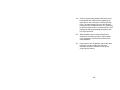
The following individuals are gratefully acknowledged for
their efforts in compiling this third edition of the “Vector
Control Equipment Performance Check List”:
Foremost, Mr. Nelson E. Desormier, whose years of
dedication and expertise were critical in transcribing and
updating selected content from instruction manuals, adding
critical missing steps, and simplifying pesticide dispersal
equipment procedures contained in this check list. It was
he who initiated, contributed and/or assisted in the
completion of the first, second and third editions.
Dr. W. Tozer, served as formal editor for the 1993 and
2005 editions, and was responsible for chapter content,
design layout, organization, formatting and all digital
enhancements, composites, or modifications of photos and
illustrations.
For earlier first drafts of the 2005 version, HM1 K.
Compton, HM1 M. Elam, and HM3 J. Church provided
valuable technical assistance, methodically “beta testing”
the “Check List” over a period of weeks with Mr.
Desormier. HM1 M. Elam was responsible for volunteering
to retype and transcribe the first draft of the 2005 version
from the 1993 version. The current version has been
updated May 2006.
Credits: fig. 1, Curtis Dyna-Fog, Ltd.; figs. 2, 50 (Insert), 51
through 60; Clarke Mosquito Control Products, Inc.; figs. 37, HM1 M. Elam (retired), NDVECC, Bangor, WA; figs. 8,
48 through 50, NDVECC Bangor, WA; fig. 9 through 35,
Stihl Inc.; figs. 36 through 47, Solo; fig. 62, CDR M.
ii
Medina, NEPMU5, San Diego, CA; fig. 63, Honda Motor
Co., Inc.
DISCLAIMER
At the date of publication, every effort has been made to
ensure the accuracy of its content. This publication was
intended for educational purposes only. Trade names are
used in this check list to provide specific information and
do not imply endorsement of the products named or
criticism of similar ones not mentioned. Mention of trade
names does not constitute a guarantee or warranty of the
products by the Navy Environmental and Preventive
Medicine Unit Five, San Diego, the Military Services or the
Department of Defense (DoD).
iii
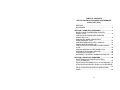
TABLE OF CONTENTS
VECTOR CONTROL EQUIPMENT PERFORMANCE
CHECK LIST (PCL)
PREFACE .........................................................................I
DISCLAIMER .................................................................. III
SECTION I: HAND HELD EQUIPMENT ........................... 1
B AND G HAND COMPRESSED SPRAYER
MODEL 124CC ............................................................... 2
CURTIS HAND COMPRESSED SPRAYER
MODEL 2981 PCC.......................................................... 6
HUDSON TEK HAND COMPRESSED
SPRAYER MODEL 67132 ............................................ 10
CENTROBULB BULB DUSTER - MODEL B ................ 14
CHAPIN DUSTER MODEL 599 .................................... 16
CURTIS DYNA-FOG THERMAL FOGGER, MODEL
2610E............................................................................ 18
HUDSON ADMIRAL DUSTER MODEL 6766 ............... 24
MICRON ULVA FAN MK II SPRAYER.......................... 26
CLARKE (LECO) MODEL P-1 ...................................... 30
WHITMIRE PT SYSTEM III HANDHELD SPRAYER .... 36
SECTION II: BACKPACK SPRAYERS........................... 43
KIORITZ BACK PACK MODEL ECHO DM-9
(2-CYCLE ENGINE)...................................................... 44
SOLO BACKPACK MODEL 423 (2-CYCLE ENGINE).. 54
STIHL BACKPACK MODEL SR400 (2-CYCLE ENGINE)
...................................................................................... 61
SOLO 475 BACKPACK SPRAYER (DIAPHRAGM
PUMP) .......................................................................... 82
iv
SECTION III: HYDRAULIC SPRAYERS ......................... 97
FARM TEC MODELATE-20:......................................... 98
HUDSON MODEL 47200 DL SPRAYER .................... 101
JOHN BEAN HYDRAULIC POWER SPRAYER
MODEL DM10E 150 ................................................... 105
JOHN BEAN PLC MODEL DP05E/30 PRB ................ 111
SMITHCO MODEL 6911............................................. 114
SECTION IV: VEHICLE MOUNTED ULV SPRAYERS. 119
BEECO PRO-MIST 15MP ULV SPRAYER................. 120
CURTIS MODEL 2740 ULV SPRAYER ...................... 130
CURTIS MODEL 2742 ULV SPRAYER ...................... 136
CURTIS MODEL 2952 ULV SPRAYER ...................... 142
CLARKE (LECO) GRIZZLY ULV SPRAYER .............. 148
LECO MODEL 800 ULV SPRAYER............................ 166
LECO MODEL HD 1600 ULV SPRAYER.................... 171
LONDON AIRE XK ULV SPRAYER............................ 176
LONDON FOG MEDIUM AIR GENERATOR (MAG) ULV
SPRAYER................................................................... 181
MICROGEN ED2-20A ULV SPRAYER....................... 191
MICROGEN (G-9HD) ULV SPRAYER........................ 196
PESTICIDE AERIAL CARGO UNIT (PACU-9) ........... 202
SECTION V: VINTAGE VECTOR CONTROL
EQUIPMENT .................................................................. 213
ACME CYANOGAS FOOT PUMP MODEL 50............ 214
BEECO WHISPERMIST XL MODEL 200 ULV SPRAYER
.................................................................................... 217
MICROGEN HCS1-2AA.............................................. 221
SECTION VI: ADDITIONAL FD-PMU/AMAL VECTOR
CONTROL EQUIPMENT ............................................... 225
AG- SPRAYER
v
MODEL AG-25 SPEL.................................................. 226
HONDA ALL TERRAIN VEHICLE (ATV) .................... 229
vi
SECTION I:
HAND HELD EQUIPMENT
1
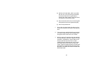
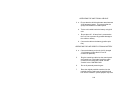
PERFORMANCE CHECKLIST FOR THE
B AND G HAND COMPRESSED SPRAYER
MODEL 124CC
SET-UP PROCEDURES
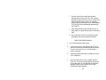
1.
Unscrew and gently remove the rod/piston
assembly from the cylinder.
2.
Examine the leather piston cup to ensure that it is
pliable and not cracking. Lubricate the piston cup
with a small amount of oil (engine oil, mineral oil,
etc.), if necessary. Some cups are now made of
plastic rendering this step unnecessary.
3.
Remove the cylinder from the tank.
4.
Examine the gasket located under the lip of the
cylinder. Replace the gasket if it is worn (i.e.,
chipped or torn).
5.
Examine the cylinder check valve located at the
bottom of the cylinder. Replace it when necessary.
6.
Examine the pesticide hose. Be sure that the
connection sites at the tank and the spray wand
are not worn.
7.
Unscrew the wand where it connects to the
pesticide line and pull out the inline filter. Clean
the filter in solvent as required. Screw the unit back
together.
2
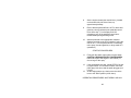
8.
Select the required nozzle and screw onto the tip
of the wand. If using a Multi-jet nozzle, loosen the
retaining collar on the nozzle and rotate it to the
desired setting, making sure that the aperture is
directly over the pesticide exit hole in the wand.
9.
Check for proper pressurization and the possibility
of leaks in the system by adding water to the tank.
Leave approximately 1/3 of the tank empty for air.
10.
Replace the rod/piston assembly to the cylinder by
placing the piston cup at a 45-degree angle and
pushing the piston gently into the cylinder. Ensure
that the piston cup does not crimp or buckle or a
good seal will not develop.
11.
To properly pressurize the tank, pump the unit 6-10
times. Depress the trigger on the wand. Check for
water and air leaks in the tubing and various seals.
OPERATING PROCEDURES
12.
Discontinue spraying the water and SLOWLY twist
the handle to allow the pressurized air to escape.
13.
Remove the cylinder and dump out the water.
14.
Put on all personal protective gear.
15.
Calculate the exact amount of pesticide
concentrate required for the operation.
3
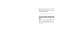
16.
Add the calculated amount of carrier first and then
add the pesticide, through a 60-mesh screen filter,
to bring the solution up to the label's
recommendation.
17.
Screw the pump cylinder back in.
18.
Gently agitate the tank to allow proper mixing of
the pesticide.
19.
Pump the sprayer 4-5 times (for pin stream
applications) or approximately 20 times, or until it
becomes more difficult to pump (for fan spray
applications). The optimum pressure for fan
spraying is approximately 40 psi, which is about 20
pumps.
20.
Dispense the pesticide by depressing the wand's
trigger. For crack and crevice or pin stream
applications, the nozzle should be placed as close
as possible against the area to be sprayed, or
inserted directly into a crack or crevice when using
an insertion tip. For fan spraying, the nozzle
should be kept 18-24 inches away from the target
area.
21.
Keep the tank pressure up by pumping air into the
tank as required.
22.
FOR SAFETY REASONS, NEVER RAISE THE
WAND ABOVE YOUR HEAD.
4
TERMINATING PROCEDURES
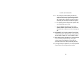
23.
Gently unscrew the cylinder from the tank until all
of the pressurized air inside the tank has been
released and then remove the cylinder.
24.
Transfer any remaining pesticide into a LABELED,
NONBREAKABLE CONTAINER.
25.
Clean the sprayer thoroughly using a detergent
that will remove the pesticide. Replace the
cylinder and pressurize the tank.
26.
Depress the wand trigger to allow the cleaning
solution through the wand assembly and nozzle.
27.
Triple-rinse the tank and wand assembly with
water by repeating the described procedure.
28.
Store the sprayer with the tank open and inverted
to allow for proper drying.
5
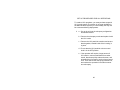
PERFORMANCE CHECKLIST FOR THE
CURTIS HAND COMPRESSED SPRAYER
MODEL 2981 PCC
(NSN 3740-00-191-3677)
SET-UP PROCEDURES
1.
Unscrew and gently remove the rod/piston
assembly from the tank.
2.
Unscrew the cylinder from the pump handle.
Examine the O ring at the bottom of the rod and
lubricate as needed with a small amount of oil.
3.
Examine the cylinder check valve located at the
bottom of the cylinder. Check the O ring at the top
of the cylinder. Reassemble the cylinder and pump
handle rod.
4.
Examine the pesticide hose for wear/cracks etc.
Make sure all hose connection sites at the tank
and the spray wand are not worn.
5.
Unscrew the wand where it connects to the
pesticide hose and pull out the inline filter. Clean
the filter as required. Screw the unit back together.
6.
Select the required (TeeJet) nozzle required for the
spray mission and screw onto the tip of the wand.
6
7.
Check for proper pressurization and the possibility
of leaks in the system by adding water to the tank.
Leave approximately 1/3 of the tank empty for an
air gap.
8.
Replace the rod/piston assembly cylinder back into
the tank.
9.
To properly pressurize the tank, pump the unit 6-10
times. Depress the trigger on the wand. Check for
water and air leaks in the hose, tubing, wand and
tank seals. Repair all leaks.
10.
Discontinue spraying the water and slowly relieve
the tank pressure by turning knurled nut
counterclockwise where hose connects to the top
of the tank.
11.
Remove the pump assembly and dump out the
water.
OPERATING PROCEDURES
12.
Put on all personal protective gear.
13.
Calculate the exact amount of pesticide needed for
the operation.
14.
Add the calculated amount of carrier first and then
add the pesticide through a 60-mesh screen filter,
to bring the solution up to the label's
recommendation.
7
15.
Screw the pump assembly back in.
16.
Gently agitate the tank to allow proper mixing of
the pesticide and carrier (as needed).
17.
Pump the sprayer 4-5 times (for pin stream
applications) or approximately 20 times, or until it
becomes harder to pump (for fan spray
applications). The optimum pressure for fan
spraying is approximately 40 psi.
18.
Dispense the pesticide by depressing the wand's
trigger. For crack and crevice or pin stream
applications, the nozzle should be placed as close
as possible against the area to be sprayed, or
inserted firmly into a crack or crevice when using
an insertion tip. For fan spraying, the nozzle
should be kept 18-24 inches away from the target
area.
19.
Keep the tank pressure up by pumping air into the
tank as required.
20.
FOR SAFETY REASONS, NEVER RAISE THE
WAND ABOVE YOUR HEAD.
TERMINATING PROCEDURES
21.
Gently/slowly unscrew the knurled knob where the
hose connects to tank to relieve the pressure
remaining in the tank. The remove the tank pump
assembly.
8
22.
Transfer any remaining pesticide into a LABELED,
NON-BREAKABLE CONTAINER.
23.
Clean the sprayer thoroughly at this time by adding
liquid detergent/water mixture. Replace pump
assembly and re-pressurize the entire system.
24.
Depress the wand trigger and flush cleaning
solution through hose and wand assembly.
25.
Triple-rinse the tank and wand/hose assembly with
water by repeating steps 23 and 24.
26.
Store the sprayer with the tank open and inverted
to allow to properly air dry. Remember to hold up
wand, depress trigger to bleed all liquid out of
wand, trigger and hose.
9
PERFORMANCE CHECKLIST FOR THE
HUDSON TEK HAND COMPRESSED
SPRAYER MODEL 67132
SET-UP PROCEDURES
1.
Rotate the handle on the tank and remove the
cover.
2.
Examine the gasket on the tank cover and replace
it if it is worn.
3.
Unscrew and gently remove the rod / piston
assembly from the cylinder.
4.
Remove the cylinder from the tank and examine
the gasket located at the top of the cylinder and
replace if worn.
5.
Examine the cylinder check valve located at the
bottom of the cylinder. If worn, replace the check
valve.
6.
Examine the leather piston cup on the bottom of
the piston to ensure that it is still pliable and not
cracking. If necessary, lubricate the cup with a
small amount of oil (any type of oil will do: engine,
mineral, etc.).
7.
Return the cylinder to the tank with the extended
lip pointed toward the outer rim of the tank.
10
8.
Return the rod / piston assembly to the cylinder by
placing the piston cup at a 45 degree angle and
then gently pushing the piston into the cylinder.
Make sure that the piston cup does not crimp or
buckle -- or a good seal will not develop.
9.
Examine the pesticide hose. Be sure that the
connection sites at the tank and the spray wand
are not worn.
10.
Unscrew the wand where it connects to the
pesticide line and pull out the inline filter. Clean
the filter in solvent as required. Screw the unit back
together.
11.
Select the proper spray flow by loosening the
retaining collar on the nozzle and rotating the
nozzle to the desired setting. Screw the collar
back on making sure that the selected aperture is
directly over the pesticide exit hole in the wand.
12.
Check for proper pressurization and for of leaks in
the system by adding water to the tank. To
properly pressurize the tank, fill only about 2/3 full,
leaving about 1/3 of the tank empty for air. Replace
the tank cover and pump the unit 6-10 times.
Depress the trigger on the wand. Check for water
and air leaks in the tubing and all seals.
11
OPERATING PROCEDURES
13.
Discontinue spraying the water and release the
pressure inside the tank by depressing the air
release valve, located on the tank cover.
14.
Remove the tank cover and dump out the water.
15.
Put on all personal protective gear.
16.
Calculate the amount of pesticide concentrate
required for the operation.
17.
Add the calculated amount of carrier first and then
add the pesticide, through a 60-mesh screen filter,
to bring the solution up to the label's
recommendation.
18.
Replace the tank cover and gently agitate the tank
to allow proper mixing of the pesticide.
19.
For pin stream applications, pump the sprayer 4-5
times. For fan spray applications, pump the
sprayer about 20 times, or until it becomes hard to
pump. (The optimum pressure for fan spraying is
approximately 40 psi, which is about 20 pump
strokes.)
20.
Dispense the pesticide by depressing the wand's
trigger. For crack and crevice, or pin stream
applications, the nozzle should be placed as close
as possible up against the area to be sprayed.
12
For fan spraying, the nozzle should be kept 18-24
inches away from the target area.
21.
Keep the tank pressure up by pumping air into the
tank as required.
22.
FOR SAFETY REASONS, NEVER RAISE THE
WAND ABOVE YOUR HEAD.
TERMINATING PROCEDURES
23.
Release the pressure from the tank using the air
release valve and remove the tank cover.
24.
Transfer any remaining pesticide into a
LABELLED, NONBREAKABLE CONTAINER.
25.
Clean the sprayer thoroughly using a detergent
that will remove the pesticide. Replace the tank
cover and pressurize the tank.
26.
Depress the wand trigger to allow the cleaning
solution through the wand assembly and nozzle.
27.
Triple-rinse the tank and wand assembly with
water by repeating the described procedure.
28.
Store the sprayer with the tank open and inverted
to allow for proper drying.
13
PERFORMANCE CHECKLIST FOR THE
CENTROBULB BULB DUSTER - MODEL B
(NSN: 3740-01-441-5250)
SET-UP PROCEDURES
1.
Unscrew the metal tip nozzle from the housing.
2.
To avoid spillage of the material, use a funnel to
pour the pesticide (REMEMBER, ONLY DUSTS
AND POWDERS) into the rubber housing.
3.
Screw the nozzle back onto the housing.
OPERATING PROCEDURES
4.
Place the tip of the nozzle so that it is parallel with
the surface to be treated and squeeze the rubber
bulb GENTLY to produce fine puffs of pesticide dust,
which LIGHTLY cover the target surface. Avoid
excessive clumping, as arthropods are less likely to
walk through mounds of powder.
5.
Rotate unit periodically while spraying to prevent
pesticide from clumping near base of the nozzle.
TERMINATING PROCEDURES
6.
It is not necessary to return the unused portion of
the pesticide to its original container. Cover the
nozzle tip using some type of material (e.g., cork,
14
aluminum foil, to prevent the pesticide from being
accidentally expelled.
7.
Store the unit in a dry area.
15
PERFORMANCE CHECKLIST FOR THE
CHAPIN DUSTER MODEL 599
SET-UP PROCEDURES
1.
Apply a small amount of lubricating oil of medium
viscosity to the four (4) bearings designated by
"OIL" stamped at each of the bearings. This
should be done at least once a day during the
operating season.
2.
Check the gear case, located directly below the
handle, and fill it with at least 2 tablespoons of
light, graphite grease.
3.
Put on your personal protective gear.
4.
Pull open the top of the duster and add the dust.
Ensure that the pesticide is thoroughly dry and free
of foreign material. Replace the tank cover.
5.
Strap the duster onto your shoulders and adjust it
so that the brace rests comfortably on your waist.
6.
Add the extender wand to the flow outlet. The fan
shaped tip can be removed as needed.
OPERATING PROCEDURES
7.
Rotate the crank at the desired speed to achieve
the optimum flow rate.
16
8.
Adjust the pesticide flow rate by pulling the slide
bar located on the discharge tube directly below
the tank. To increase the flow, pull the bar, and to
decrease the flow, push the bar back into its
housing.
TERMINATING PROCEDURES
9.
Remove the duster from your shoulders and empty
the remaining dust back into the original container.
10.
Triple-rinse the duster and make sure that no dust
remains in the tank, the beater tube, the fan case,
or the discharge tubes.
11.
Air-dry the tank before you store the unit in a dry
area.
17
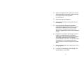
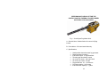
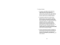
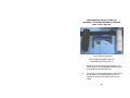
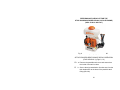
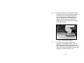
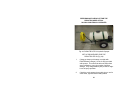
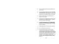
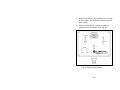
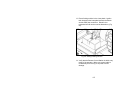
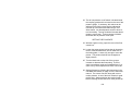
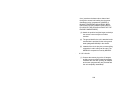
PERFORMANCE CHECKLIST FOR THE
CURTIS DYNA-FOG THERMAL FOGGER, MODEL
2610E (NSN: 3740-00-818-6648)
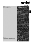
Fig. 1. Curtis-Dyna-Fog Model 2610.
A. General Uses: Outdoor/Indoor for control of flying
insects.
B. Formulations: Oil base insecticides only.
C. Specifications:
•
•
•
•
•
•
•
•
•
Hand portable thermal aerosol fog generator.
Resonant pulse-jet engine
Insecticide output: 0 –9 gallons/hour
Thumb trigger formulation control
Air volume at nozzle: 250 cubic ft/min
Air velocity at nozzle: 50 mph
Fog particle size: 0.5 – 50 microns
Fuel tank capacity: 0.85 quarts
Insecticide tank capacity: 1 gallon
18
•
•
•
Engine: 30 HP, 0.5 GPH
Power supply:
• 8 – “1.5V, D” Cell batteries
• 12-volt plug (cigarette lighter)
Weight empty: 19 lbs; filled 27 lbs
D. Description: The fog generator employs the resonant
pulse principle (pulse-jet) to generate hot gases flowing
at high velocity. The high velocity gases atomize the
formulation instantly. The machine is intended for
outdoors use and for enclosed spaces with volumes of
more than 500 cubic feet. Use in more confined spaces
may create a fire or explosion hazard.
19
E. Working Principles:
1. The engine is essentially a hollow tube with an
intake valve and a means of supplying a
combustible mixture of fuel and air at one end
(intake), and a clear opening at the other (exhaust).
Close to the intake end is an expanded section of
the tube, which acts as a combustion chamber.
2. An air pump is used to force a mixture of fuel
(gasoline) and air into the combustion chamber.
The fuel mixture is initially ignited by a spark plug,
which is powered by an electronic ignition system.
After the initial ignition, the repeated cycles are then
sustained by a glow-coil. A series of pulse
explosions occur in the combustion chamber
resulting in a positive pressure pushing the hot
gases (1800°F) out through the exhaust tube. As
the spent fuel exits the combustion chamber a
negative pressure is formed which opens the fuel/air
valves and draws another appropriate amount of fuel
mixture into the combustion chamber.
3. The fog is generated by injecting the pesticide (oil
base only) into the exhaust tube at the proper point
where it is then broken down by the high velocity,
cyclic flow of the hot gases. At this point the
pesticide is vaporized into fine particles and ejected
out the exhaust.
20
PRE-OPERATION OF THE CURTIS DYNA-FOG
MODEL 2610 (Fig. 1)
1.
Fuel: filtered (#60 mesh size) regular unleaded gas
only. Never try to refuel a machine that is hot.
2.
Batteries: (8) 1.5V “D” Duracell
3.
Insecticide: oil base only, filtered through a 100mesh screen
STARTING/STOPPING PROCEDURES
4.
Lift then press down the “ON/OFF” control knob to
the “ON” position.
5.
Depress and release the “primer bulb” repeatedly
until fuel is visible in the “primer bulb”.
6.
Once fuel has reached the “primer bulb”, depress
and release the bulb 3 times for a cold engine/1
time for restarting a hot engine.
7.
Simultaneously depress “ignition” and “air” buttons
until engine begins to start, then release the “air”
button and continue depressing the “ignition”
button until engine runs smoothly (CAUTION.
HEARING PROTECTION REQUIRED).
8.
If engine has not started within 40 seconds, repeat
steps 3 and 4.
21
9.
To stop the engine, lift the control knob to the “off”
position.
FOGGING
10.
Verify that the formulation and fuel tank caps are
tight.
11.
Start engine as specified in the above section.
12.
Allow engine 1-2 minutes running time to warm up
to operating temperature.
13.
Set formulation-metering valve (flow rate) to
desired fog quality.
14.
Push formulation valve button (thumb trigger) to
fog.
15.
Close metering valve immediately after fogging;
allow any pesticide remaining in lines to flush,
before shutting engine off.
MAINTENANCE
16.
After each use, drain any unused formulation from
the tank into its original container for proper
storage by removing 7/16” plug at bottom of the
formulation tank.
17.
Flush out machine with approved flushing solvent
after draining out formulation tank.
22
18.
After 4-hours of operation, clean exhaust tailpipe
with clean-out brush provided with the unit.
19
After 8-hours of Operation:
20.
(a)
Remove spark plug and scrape loose carbon
in engine neck.
(b)
Spark plug gap is .060 inches. Install hand
tight only with rubber O-ring installed on plug.
(c)
Remove and clean formulation filter.
After 12 hours of operation:
(a)
Check fuel filter located inside housing unit
near engine.
(b)
Remove and clean formulation injection orifice
located in-line, midway under the exhaust
tube. Use aerosol carburetor cleaner or
approved solvent.
21.
Always remove batteries prior to storage.
22.
After cooling down with a general purpose cleaner
(i.e., Spray On-Wipe Off or equivalent), wash off
exterior of machine.
23
PERFORMANCE CHECKLIST FOR THE
HUDSON ADMIRAL DUSTER MODEL 6766
SET-UP PROCEDURES:
1.
Unscrew the top of the unit and remove the
plunger.
2.
Examine the piston cup and lubricate the plunger
with either flake or powder graphite as necessary.
3.
Carefully return the plunger to the duster and
tighten the cap.
4.
Unscrew the cap at the discharge end of the barrel.
5.
Fill the opened pesticide compartment 3/4 full.
Ensure that the dust is dry and free from lumps.
Secure the cap.
OPERATING PROCEDURES:
6.
Point the nozzle in the intended direction and push
the plunger in short, easy strokes, which will send
out a well mixed discharge of dust that gives
uniform coverage and lightly covers the target
surface. Excessive clumping of the pesticide
should be avoided, as arthropods are less likely to
walk through mounds of powder.
24
7.
Attach the long extension wand if required. The
adjustable nozzle allows the dust to be dispensed
up, down, or sideways, and to treat hard to reach
areas.
TERMINATING PROCEDURES
8.
Return the unused portion of the pesticide to its
original container.
9.
Depress the plunger several more times to clear
out the system.
10. Store the unit in a dry area.
25
PERFORMANCE CHECKLIST FOR THE
MICRON ULVA FAN MK II SPRAYER
(NSN: 3740-01-206-9636)
TESTING OF ENVIRONMENTAL CONDITIONS
FOR ULV APPLICATION
A.
Check the weather conditions expected during the
spray operations, REMEMBER, YOU SHOULD NOT
CONDUCT ULV OPERATIONS IN THE RAIN OR IN
STRONG WINDS.
B.
Check for a temperature inversion. A temperature
inversion has occurred when the air temperature at
six feet above the ground is at least one degree
warmer than the ground temperature (This situation
usually occurs in the early morning and late evening
hours).
C.
Check the wind speed by using a wind-measuring
device. The indicated wind speed should fall
between 4-6 MPH and should be blowing across the
intended target area.
SET-UP PROCEDURES
1.
Plug the battery charger into the gel-cell battery.
Charge the battery following a 2 hours on: 2 hours
off schedule until the battery has at least an 80%
charge. DO NOT FOLLOW THE RECHARGING
INSTRUCTIONS IN THE OPERATOR'S MANUAL
OR THE LIFESPAN OF THE BATTERY WILL BE
DRASTICALLY REDUCED.
26
2.
Remove the ULVA fan from its case and open the
unit at its hinge.
3.
Ensure that all of the electrical connections are
clean, tight, and fit properly.
4.
Select the appropriate color coded feed nozzle
(read the pesticide label); holding the unit right side
up, drop the nozzle into the motor housing, located
at the front of the machine, which also contains the
revolving atomizer disc.
5.
Put on all personal protective gear (respirator).
6.
Choose an appropriate ULV pesticide concentrate
(read the label) and pour the pesticide into one of
the 1/2 liter bottles, provided and label it.
7.
Invert the machine and screw the 1/2 liter bottle into
the motor housing.
8.
Keep the bottle right side up until the spraying
operation is ready to proceed.
9.
Remove the plastic protective cover from the
atomizer disc.
OPERATING PROCEDURES
10.
Before actually starting operations, check the
wind's speed and direction with an anemometer.
Make sure that the pesticide is sprayed
DOWNWIND.
27
11.
Put on the battery using the shoulder strap
provided.
12.
Plug the ULVA FAN into the battery. Ensure that
the battery switch is ON. You are now ready for
ULV application.
13.
REMEMBER TO WALK UPWIND WHILE
SPRAYING. OTHERWISE, YOU WILL BE
WALKING INTO THE PESTICIDE.
14.
Grab the lower handle and turn the unit upside
down so that the pesticide is flowing from the bottle
into the disc and blowing out.
15.
To stop for short periods of time, turn off the mist
by simply inverting the machine (the bottle will now
be right side up and below the unit).
16.
For long delays, invert the machine (bottle right
side up) and unplug the unit from the battery.
TERMINATING PROCEDURES
17.
Invert the machine (bottle right side up), unscrew
the bottle and replace it with another 1/2 liter bottle
filled with an approved flushing solution. CAP THE
PESTICIDE BOTTLE IMMEDIATELY.
18.
Resume the operation and run the unit for
approximately 2 minutes.
28
19.
Disconnect the unit from the battery.
20.
Invert the machine (bottle down) and remove the
bottle and feed nozzle.
a. Wipe off any excess pesticide from the unit. Don't
wash/steam clean or get any water near the unit.
21.
Secure the ULVA FAN and its separate parts into
the case.
22.
Recharge the battery after each use following the 2
on/2 off schedule described in STEP 1. Note: the
battery will hold its charge for a longer period of
time when stored in a freezer or refrigerator
29
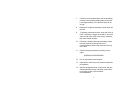
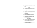
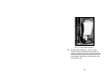
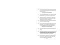
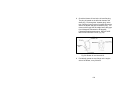
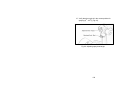
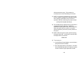
PERFORMANCE CHECKLIST FOR THE
CLARKE (LECO) MODEL P-1
(NSN: 3740-01-456-2623)
Fig. 2. LECO P-1 ULV Sprayer
30
TESTING OF ENVIRONMENTAL CONDITIONS FOR ULV
A.
Check the weather conditions expected during the
spray operations, REMEMBER, YOU SHOULD NOT
CONDUCT ULV OPERATIONS IN THE RAIN OR IN
STRONG WINDS.
B.
Check for a temperature inversion. A temperature
inversion has occurred when the air temperature at
six feet above the ground is at least one degree
warmer than the ground temperature. (This situation
usually occurs in the early morning and late evening
hours).
C.
Check the wind speed by using a wind-measuring
device. The indicated wind speed should fall
between 4-6 mph and should be blowing across the
intended target area.
SET-UP PROCEDURES FOR THE
LECO P-1 ULV SPRAYER (Fig. 2).
1.
Examine the fuel level in the gasoline tank. Fuel
note: For the first 20 hours of operation of a new
machine mix 8 oz of 2-cycle oil with 1 gallon of
unleaded gasoline. Use a mixture of 6 oz of 2cycle oil with 1 gallon of unleaded gasoline
thereafter.
2.
DO NOT MIX GASOLINE AND OIL DIRECTLY IN
THE ENGINE FUEL TANK.
31
3.
Check engine operation before filling the pesticide
tank. Place the throttle lever in the fully closed
position ("idle lever" down).
4.
Push the primer button to feed the fuel to the
carburetor until fuel overflows from the carburetor
(primer button located at bottom of carburetor).
5
Close the choke by pushing the lever up (Omit this
step if engine is already warm.)
6.
Firmly pull the starter rope until the engine starts.
CAUTION: HEARING PROTECTION REQUIRED.
Return the rope to the engine in one motion (i.e.,
do not let go of the rope).
7.
After starting the engine, gradually open the choke
by turning the choke lever down and finally keep it
fully opened.
8.
Let the engine warm up by running it at a low RPM
(slow speed) for approximately one or two minutes.
STOPPING THE ENGINE
9.
Reduce the engine RPM to idle.
10.
Stop the engine by pushing the stop button
(located between starter rope and carburetor).
32
OPERATING PROCEDURES
11. Put on all personal protective gear.
12.
Lay sprayer on its side to fill the pesticide tank (we
recommend the use of a funnel with at least 60
mesh screen to fill tank). Fill the insecticide tank to
within 1/2" of the top. When replacing the tank
cap, be sure that the O-ring is in place.
13.
Restart the engine, and then depress the throttle
level (pull up) to full rpm's. Open the control valve
to start the flow of insecticide. The engine should
always be running at its fastest speed when
discharging insecticide.
TERMINATING PROCEDURES
14.
ALWAYS close the control valve first! This stops
the flow of insecticide.
15. Release the throttle to reduce the engine RPM to
idle. NOTE: It is ABSOLUTELY NECESSARY to
close the control valve before reducing the engine
speed. If the control valve is left open with the
engine idling, the insecticide will not be atomized
and will drip from the nozzle.
CALIBRATION
16.
Fill the insecticide tank with a known measure of
insecticide.
33
17.
Set the control valve at a specific stop. NOTE:
The valve has four adjustable stops for the flow
rate setting. To change the flow rate simply
relocate the setscrew stop. (Figure 2, page 8)
FLOW RATES
18.
Knob forward (OFF).
19.
First hole 1/4 flow rate turn counter clockwise.
20.
Second hole 1/2 flow rate turn counter- clockwise.
21.
Third hole 3/4 flow rate turn counter clockwise.
22.
Fourth hole full flow rate turn counter clock-wise.
23.
Spray for a specific time. The longer this time
period, the more accurate the calibration will be.
24.
Remove the remaining insecticide from the tank
and measure. The difference in the starting and
ending measurement will be the usage for the
specific time spraying took place.
MAINTENANCE
25.
Always flush out ULV sprayer with a recommended
flushing solvent. For "field" use, you may use
transmission fluid.
34
26. Clean and re-gap sparkplug every 15 hours. For
two-cycle engines, gap plug from 0.6 to 0.7mm
(0.024" - 0.028"). Magneto: gap between coil and
the flywheel should be 0.4 to 0.5 mm.
35
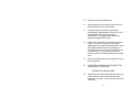
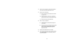
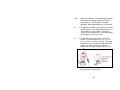
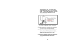
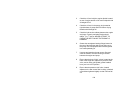
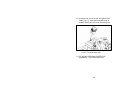
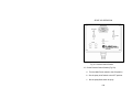
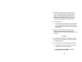
PERFORMANCE CHECKLIST FOR THE
WHITMIRE PT SYSTEM III HANDHELD SPRAYER
(NSN: 3740-01-338-5390)
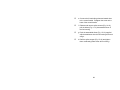
Fig. 3. Whitmire System III
SET-UP PROCEDURES FOR THE
WHITMIRE SYSTEM III (Fig. 3)
1.
Set aerosol can on a flat surface and place “Can
Clamp” (Fig. 4) in the disengaged position over the
lip of insecticide demonstration can.
2.
Turn handle to the engaged position, ensuring that
the valve stem on the insecticide demo can is
centered in the screw hole opening of the “Can
Clamp”
36
3.
Hold sprayer assembly (including Spray Gun,
Coiled Hose, Shut-Off Valve, and Valve-Clamp
Adapter) in one hand and insecticide demo can
(with “Can Clamp” attached) in the other hand.
4.
Center sprayer assembly in Can Clamp and screw
to hand tight by rotating can counterclockwise.
5.
Attach void injector to the spray gun (Fig. 5).
6.
Put on belt and pouch.
7.
Insert PT System III can into pouch.
OPERATION PROCEDURES
10.
Put on proper PPE.
11.
Open Shut-off Valve (Fig. 6) and begin “crack-and
crevice application.”
TO DISASSEMBLE
12.
To change pressurized insecticide can, first close
shut-off valve (Fig. 7).
13.
Unscrew can and Can Clamp from the sprayer
assembly. CAUTION: Do not disengage Can
Clamp without first unscrewing and detaching
sprayer assembly.
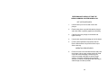
37
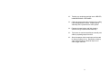
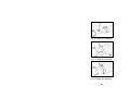
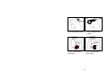
Fig. 4. Can Clamp
Fig. 6. Shut-Off Valve
open.
Fig. 5. Gun Assembly
Fig. 7. Shut-Off Valve closed.
38
TO CHANGE THE HOSE:
14.
Work Hose Spring Guards away from fittings.
15.
Unscrew hose fittings from Spray Gun and ShutOff Valve.
16.
Replace with new hose and fittings. Be sure to use
Teflon tape on both joints.
ATTACHMENT TO CYLINDER
17.
To attach PT System III to 15-lb. Whitmire cylinder,
use 15-lb. Adapter Fitting No. 14-0375.
TROUBLESHOOTING: IF THE GUN DOES NOT SPRAY
18.
Make sure the shut-off valve is in the vertical
“Open” position (Fig. 6)
19.
The insecticide can may be empty. Change PT
System III sprayer assembly to a new can.
20.
The Valve Stem may be clogged in the gun.
a.
Unscrew can and can clamp from Spray
Assembly.
b.
Point Shut-off Valve downward away from you
in a well-ventilated area, and empty Hose and
Gun by opening shut-off Valve. CAUTION:
Never spray toward plastic or painted
surfaces.
39
c.
Unscrew Spray Gun Cap, replace with new
Stem, Gasket and spring. Or clean plastic
Valve Stem by removing Gasket, and cleaning
orifice on the side of the small part of the
Valve Stem using a safety pin or other small
sharp object.
d.
Replace gasket, spring and stem into gun and
hand-tighten spray gun cap.
21.
The Valve-Clamp Adapter may not be tightly
attached to Clamp and Can. Hand Tighten.
22.
If spray comes from beneath the knurled brass
Spray Gun Cap, the cap may be loose.
a.
Hand Tighten.
b.
The small black Gasket in the Gun may need
replacing. To replace, follow Trouble-Shooting
Procedure 3 above.
23.
If leaking occurs between Valve-Clamp Adapter
and can, replace Valve Clamp adapter.
24.
If Shut-Off Valve leaks, the O-ring may need
replacing.
a.
Unscrew the Valve Stem Housing from the
Valve Body.
40
b.
Replace O-ring by sliding it over Shut-Off Valve
stem and into groove. If Shut-Off Valve still
leaks, it should be replaced.
SAFETY TIPS
25.
Remember: close Shut-Off Valve between jobs;
empty hose after last job.
26.
Do not attempt to use the PT System III equipment
on products not designed for PT System III. It will
cause the can valve to leak and damage the
equipment.
27.
Do not remove hose and gun from Pressurized
Insecticide Can after operation without first closing
the Shut-Off Valve.
41
42
SECTION II
BACKPACK SPRAYERS
43
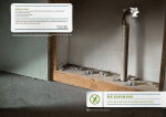
PERFORMANCE CHECKLIST FOR THE
KIORITZ BACK PACK MODEL ECHO DM-9
(2-CYCLE ENGINE)
SET-UP PROCEDURES FOR MIST SPRAYING
OPERATIONS (EXCLUDING ULV)
1. a.
Remove the pesticide tank cover and ensure that
the inside of the tank is clean.
b.
Examine the bottom of the tank to ensure that (1)
the pesticide line is secured to its metal fitting
(which is welded onto the solid plate), (2) that the
other end of the line exits the tank, and (3) that it
is secured to the unit with the plastic nut
provided. NOTE: If the solid plate at the base of
the pesticide tank and the pesticide line are
absent, they can be installed only after the tank
has been removed.
(1) Using the tools provided, remove the pesticide
tank by loosening the two red plastic nuts
located outside and underneath the tank.
(2) Simultaneously, pull the nuts outward and lift
the tank away.
44
(3) Add the solid metal plate, which is provided
with the unit, to the top of the grooved plate,
and ensure that there is a good seal by
pressing the rubber edges of the plates down,
until they are flush with each other.
(4) Secure the tank back to the unit ensuring that
both plastic tank nuts are tightened equally.
(5) Secure the pesticide line.
c.
Secure the air pressurization line that runs from
the top of the blower to the base of the pesticide
tank.
d.
Connect the outer pesticide feed line to the base
of the tank, along the top of the discharge tube,
through the inline cutoff valve, to the nozzle.
e.
With the engine off (remember that the pesticide
flow is gravity fed), examine the system for leaks
as follows: (1) add about 1 quart of water to the
tank (2) open the inline flow valve, located
midway along the discharge tube, and (3) open
the volume control cock located on top of the
nozzle. Tighten all leaking areas as required and
then drain any remaining water from the system.
BE SURE TO PURGE THE WATER FROM THE
PESTICIDE LINE.
45
SET-UP PROCEDURES FOR ULV OPERATIONS
To conduct ULV operations, you must purchase a special
ULV nozzle system. The system is no longer available in
the National Stock System (no current NSN), but may still
be encountered during deployments.
2. a. Set up the unit into the mist spray configuration
as described above.
b. Remove the mist spray nozzle and replace it with
the ULV nozzle.
c. Remove the ULV pesticide container and ensure
that the gasket, located inside of the housing, is
in place.
d. Ensure that the ULV pesticide volume control
knob is in the OFF position.
e. If the operation will require a large amount of
ULV solution, remove small bottle from under
nozzle, disconnect pickup tube and screen, and
reinstall tubing from tank to under volume control
cock. Then connect the mist spray pesticide line,
and conduct the operation in the same manner
as a mist spray.
46
SET-UP PROCEDURES FOR DUSTS AND GRANULES
Start this procedure with the assumption that the unit is in
the mist spray configuration.
3. a.
Disconnect and remove the air pressurization line
that runs from the top of the blower to the base of
the pesticide tank. Plug the openings with the
attached stoppers.
b.
Disconnect and remove the entire outer pesticide
feed line and the nozzle.
c.
Remove the pesticide tank cover and ensure that
the inside of the tank is clean and dry.
d.
Disconnect and remove the pesticide feed line
from inside of the tank and plug the pesticide line
exit hole with the stopper provided.
e.
Using the tools provided, remove the pesticide
tank by loosening the two plastic nuts located
outside and underneath the tank.
f.
Simultaneously pull the nuts outward and lift the
tank away.
g.
Remove the solid metal plate from the base of
the unit.
h.
Ensure that the dust volume control lever, located
on the bottom left side of the frame and inside of
the throttle control lever, is off (all the way down).
47
i.
Examine the granule metal plate. With the
pesticide control lever still in the "OFF" position,
the gates should be closed. If this is not the case,
reset the plate properly making sure that the
rubber gasket is flush with the unit. REMEMBER
TO FOLLOW THE GUIDE MARK DRAWN ON
THE PLATE.
j.
Open the pesticide control lever all the way. In
this position, the gates should also be completely
open.
k. Secure the tank back to the unit ensuring that
both plastic tank nuts are tightened equally.
PRE-START PROCEDURES
4.
Put on all personal protective gear.
5.
Check the fuel level in the gasoline tank. Fill the
tank as needed with unleaded gasoline mixed with
2-cycle oil at a ratio of 6 oz. of oil mixed with 1
gallon of gasoline.
6.
Open the gasoline flow valve, located on the front
of the carburetor.
7.
Place the choke lever in the "CHOKE" position
(lever up). The lever is located behind the air filter
on the carburetor. IF THE ENGINE IS ALREADY
WARM, PLACE THE LEVER IN THE "RUN"
POSITION (LEVER DOWN).
48
8.
Set the engine throttle (the outside lever), located
on the bottom left side of the frame, up
approximately halfway.
9.
Ensure that the pesticide flow is off. For dusts and
granules, close (push down) the pesticide control
lever all the way. For mist spray and ULV
operations, turn off the pesticide control lever
located halfway along discharge tube.
10.
Add the pesticide to the appropriate container.
(Add the pesticide to the ULV container if using the
unit for ULV, or to the pesticide tank if conducting
mist- spray, dust and granules, or large scale ULV
operations.)
START-UP PROCEDURES
11.
Firmly pull the starter rope until the engine starts.
CAUTION: HEARING PROTECTION REQUIRED.
Return the rope to the engine in one motion (i.e.,
do not let go of the rope).
12.
If the engine does not start, repeat STEPS 5-8 and
try again. NOTE: If it still does not start, check the
point gap (0.3-0.4mm) and the spark plug gap (0.60.7mm).
As the engine warms up, slowly move the choke
lever to the "RUN" position (lever down).
13.
OPERATING PROCEDURES: MIST SPRAY AND ULV
49
14. a. Set the engine throttle at half speed, and after the
engine is operating smoothly, open up the inline
flow valve (mist spray and large ULV operations),
and the volume control cock.
b. Calibrate the system. (The liquid must pass
through the metering system and must be
separate from the air flow.)
c. For adjusting the liquid flow rate to the label and
application specifications, use the volume control
cock.
d. The spray pattern may be adjusted between pin
stream and fan spray by loosening the collar
tightening nut, located at the end of the nozzle,
and moving the mist collar out (pin stream) or in
(fan spray).
50
DUSTS AND GRANULES
15. a. Set the engine throttle halfway and after the
engine is running smoothly, open the pesticide
control lever all the way. (With the engine set at
half throttle and the pesticide control lever open
all the way, the unit will put out about 5 kg/min.)
b. For adjusting the dust and granule dispersal rate,
use the pesticide control lever.
c. DO NOT BEND THE NECK OF THE HOSE
DURING SPRAY OPERATIONS. The dust can
blow back into the blower and soil or damage the
unit.
16. REMEMBER THAT WHEN CONDUCTING SPRAY
OPERATIONS WITH BACKPACKS, YOU SHOULD
ALWAYS BE UPWIND OF YOUR TARGET AREA.
17. When stopping spray operations for a short period of
time, turn off the pesticide flow by closing the
volume control cock (liquids) or by moving the
pesticide control lever down (dusts and granules).
18. For longer delays in operations, turn off the pesticide
flow and then turn the engine throttle to idle.
51
TERMINATING PROCEDURES
19.
With the engine throttle at idle, drain the liquid
pesticide into its original container.
20.
For dusts and granules, close the pesticide control
lever, stop the engine by turning off the throttle,
and shake any remaining material back into the
original container.
ULV OPERATIONS
21. a. Add an approved flushing solution to the empty
pesticide tank (such as BEECO Pro-Flush).
b. Resume operations at half engine speed and
reset the volume control cock to maximum. Run
until all of the flushing solution has been
expelled. (Be aware that this process may cause
a sudsing effect in the pesticide tank.)
22.
Fill the empty pesticide tank with detergent and
water and run until the spray is clear, there are no
more suds, and there is no longer any water inside
of the tank.
23.
Allow the machine to cool down by running it at idle
for at least 2 minutes.
24.
Close the gasoline control valve located under the
gas tank.
25.
After use, wash off the exterior of the sprayer.
52
26.
For long-term storage, drain the gasoline tank by
turning off the gasoline flow valve and then running
the engine; this will burn off all of the fuel in the
carburetor. Remove the fuel line at the carburetor
and drain the fuel into an approved gasoline
storage container.
27.
Store the backpack in a clean and dry storage
area. Cover with a 30-gallon plastic trash bag.
53
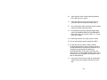
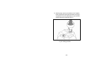
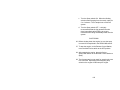
PERFORMANCE CHECKLIST FOR THE
SOLO BACKPACK MODEL 423 (2-CYCLE ENGINE)
(NSN: 3740-01-157-4000)*
Fig. 8. Solo Backpack Sprayer, Model 423
SET-UP PROCEDURES FOR MIST SPRAY
OPERATIONS (EXCLUDING ULV) (Fig. 8)
1. a.
b.
Remove the pesticide tank cover and ensure that
the inside of the tank is clean. On inside of lid
check gasket for wear – could leak. Check filter.
Secure the air pressurization line that runs from
the top of the blower to the base of the pesticide
tank.
54
c.
Connect the outer pesticide feed line to the base
of the tank, along the top of the discharge tube,
through the inline cutoff valve, to the nozzle.
d.
With the engine off, (remember that the pesticide
flow is gravity fed), examine the system for leaks
by adding approximately 1 quart of water to the
tank and opening the inline flow valve, located
midway along the discharge tube, and the
volume control cock located on top of the nozzle.
Tighten all leaking areas as required and then
drain any remaining water from the system. BE
SURE TO PURGE THE WATER FROM THE
PESTICIDE LINE.
SET-UP PROCEDURES FOR ULV OPERATIONS
To conduct ULV operations, you must purchase a special
ULV nozzle system.
2. a.
Set up the unit into the mist spray configuration
as described above.
b.
Remove the mist spray nozzle and replace it with
the ULV nozzle and slide bar.
c.
Ensure that the ULV pesticide volume control
knob is in the off position.
55
SET-UP PROCEDURES FOR DUST AND GRANULAR
OPERATIONS
3. a.
Assuming that the unit is in the mist spray
configuration, disconnect and remove the air
pressurization line that runs from the top of the
blower to the base of the pesticide tank.
b.
Disconnect and remove the entire outer pesticide
feed line and the nozzle.
c.
Remove the pesticide tank cover and ensure that
the inside of the tank is clean and dry.
d.
Disconnect and remove the air pressurization line
and strainer from the inside of the tank. Install the
ventilation distributor attachment into the left side
of the tank and the top of the blower.
e.
Remove the plastic discharge blower elbow and
replace it with the special dust discharge elbow.
This elbow has an additional ribbed hose coming
off of it.
f.
Connect the ribbed hose to the base of the
pesticide tank.
PRE-START PROCEDURES
4.
Put on all of your protective gear.
56
5.
Check the fuel level in the gasoline tank. Fill the
tank as needed with unleaded gasoline mixed with
2-cycle oil at a ratio of 2.6 ounces of oil mixed in
with 1 gallon of gasoline.
6.
Open the inline gasoline flow valve, located at the
base of the gasoline tank. Push primer button
located right rear of carburetor 4 to 5 times.
7.
Place the choke lever in the "CHOKE" position
(lever down). The lever is located behind the air
filter on the carburetor. IF THE ENGINE IS
ALREADY WARM, PLACE THE LEVER IN THE
"RUN" POSITION (LEVER UP).
8.
Set the engine throttle lever in the middle position.
The lever is located on the left side of the frame.
9.
Ensure that the pesticide flow is off. For dusts and
granules, twist the pesticide discharge tube all the
way to the vertical position (Handle up). For mist
spray and ULV operations, turn off the pesticide
control lever located halfway along the discharge
tube at the top of the control handle.
10.
Add the pesticide to the pesticide tank.
START-UP PROCEDURES
11.
Firmly pull the starter rope until the engine starts.
CAUTION: HEARING PROTECTION REQUIRED.
Return the rope to the engine in one motion; do not
let go of the rope.
57
12.
If the engine does not start, repeat STEPS 5 - 8
and try again. If it still does not start, check the
spark plug gap (0.020mm). Because it has an
electronic ignition, there are no points to gap.
13.
As the engine warms up, slowly move the choke
lever to the "RUN" position (lever up).
OPERATING PROCEDURES: MIST SPRAY AND ULV
14. a. Set the engine throttle at half speed, and after the
engine is operating smoothly, open up the inline
flow valve (mist spray and large ULV operations),
and the volume control cock.
b. Calibrate the system (The liquid must pass
through the metering system and must be
separate from the air flow).
c. For adjusting the liquid flow rate to the label and
application specifications, use the volume control
cock (mist spray) or slide bar (ULV).
DUSTS AND GRANULES
15. a. Set the engine throttle halfway and after the
engine is running smoothly, twist the plastic
discharge tubing where the pesticide feed hose
connects to it. (With the engine set at half throttle
and the pesticide discharge tube open all the
way; the unit will put out approximately 5 kg/min).
58
b. DO NOT BEND THE NECK OF THE HOSE
DURING SPRAY OPERATIONS. The dust can
blow back into the blower and soil or damage the
unit.
16. REMEMBER THAT WHEN CONDUCTING SPRAY
OPERATIONS WITH BACKPACKS, YOU SHOULD
ALWAYS BE UPWIND OF YOUR TARGET AREA.
17. When stopping spray operations for a short period of
time, turn off the pesticide flow by closing the
volume control cock (liquids) or by twisting the
plastic pesticide discharge tube (dusts and
granules).
18. For longer delays in operations, turn off the pesticide
flow and then turn the engine throttle to idle.
TERMINATING PROCEDURES:
19. With the engine throttle at idle, drain the liquid
pesticide through the pesticide feed line (located
behind the volume control valve on the nozzle) into
its original container.
20. For dusts and granules, close the discharge tube,
stop the engine by turning off the throttle, and shake
any remaining material back into the original
container.
ULV OPERATIONS
21. a. Add an approved flushing solution to the empty
pesticide tank.
59
b. Resume operations at half engine speed and
reset the volume control slide bar to maximum.
Run until all of the flushing solution has been
expelled (Be aware that this process may cause
a sudsing effect in the pesticide tank).
MIST SPRAY, DUST AND GRANULAR OPERATIONS
22. Fill the empty pesticide tank with detergent and
water and run until the spray is clear, there are no
more suds, and there is no longer any water inside
of the tank.
23. Allow the machine to cool down by running it at idle
for at least 2 minutes.
24. Close the gasoline control valve located under the
gas tank.
25. For long-term storage, drain the gasoline tank by
turning off the gasoline flow valve and then running
the engine; this will burn off all of the fuel in the
carburetor. Remove the fuel line at the carburetor
and drain the fuel into an approved gasoline storage
container.
26.
If possible, store the backpack in a clean and dry
storage area. Cover with a 30-gallon plastic trash
bag.
60
PERFORMANCE CHECKLIST FOR THE
STIHL BACKPACK MODEL SR400 (2-CYCLE ENGINE)
(NSN: 3740-01-463-0147)
Fig. 9. Stihl Backpack Sprayer, Model SR400.
SET-UP PROCEDURES FOR MIST-SPRAY OPERATION
(EXCLUDING ULV) (Figs. 9, 10)
1. a. Remove the pesticide tank cover and ensure that
the inside of the tank is clean.
b. Secure the air pressurization line that runs from the
tank basket filter to the base of the pesticide tank
fitting (left side).
61
c. Connect the outer pesticide feed line to the base of
the tank (right side), along the top of the discharge
tube through two brackets through the inline cut-off
valve, to the nozzle using two metal clamps.
d. With the engine off, (remember the pesticide flow
is gravity fed), examine the system for leaks by
adding approximately 1 quart of water to the tank
and opening the inline flow valve, located midway
along the discharge tube, and the metering knob
located on top of the nozzle is set on a number.
Tighten all leaking area as required and then drain
any remaining water from the system. BE SURE
TO PURGE THE WATER FROM THE PESTICIDE
LINE.
62
Fig. 10. Stihl Backpack Sprayer.
63
SETUP PROCEDURES FOR ULV OPERATIONS
2. a. Setup the unit into the mist-spray configuration as
described above.
b. Remove the mist-spray nozzle and replace it with
the ULV nozzle (Fig. 10-1).
c. Install one of the three optional metering nozzles
Gray in color (0.5/0.65/0.8 mm Dai.) by removing
orange colored metering knob (Fig. 10-2).
d. A strainer is fitted in the discharge tube at the base
of the pesticide tank to ensure trouble - free
operation of the ULV nozzle (Fig. 10-3).
e. Ensure that the ULV metering nozzle is in the OFF
position.
64
Fig. 11. Stihl Backpack
Fig. 12. Stihl Backpack
Fig. 13. Stihl Backpack
65
SET-UP PROCEDURES FOR DUSTS AND GRANULES
3. a. Assuming that the unit is in the mist-spray
configuration, remove retainers (Fig-11-1) from the
pleated hose to release the outer pesticide feed
line.
b. Unscrew the union nut (Fig 12-2) and pull out the
reducer (Fig. 12-3) with hose (line) (Fig 12-4).
c. Release and remove screws (Fig-13-5) take the
shut-off valve (Fig.13-6) off the control handle (Fig13-7).
d. Remove nozzle with the first straight black tube
and pesticide feed line after loosening screw at the
base of the control handle.
66
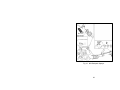
Fig. 14. DUSTS & GRANULAR SET-UP
Fig. 15. DUSTS & GRANULAR SET-UP
67
e. Connect the 3 interlocking tubes and attach them
to the control handle. Retighten the screw at the
base of the control handle.
f. Release and remove spline screws (Fig. 14-10),
pull the elbow (Fig. 14-11) downward and out of
the fan housing.
g. Push the assembled elbow (Fig. 15-12) supplied
with the attachment into the fan housing as far as it
will go.
h. Refit the spline screws (Fig. 15-10) and tighten
them moderately (Elbow must still turn freely).
68
Fig 16. Copper wire assembly.
Fig 17. Copper wire assembly.
Fig 18. Copper wire assembly.
69
i.
Attach the copper wire into hole on the right side of
elbow outlet (Fig. 16-A). Push pleated hose (Fig17-13) over the elbow outlet as far as it will go.
Copper wire is bent over as you push the pleated
hose (Fig. 17-13) into position.
j. Bend the copper wire flat forward so that the hose
clamp fits over it. (Fig. 18)
70
Fig. 19. Hose assembly.
Fig. 20. Hose assembly.
Fig. 21. Removing Bellows
Fig. 22. Removing strainer.
Fig. 23. Removing reducer Fig. 24. Securing half shells.
& hose.
71
k. Rotate the pleated hose (Fig. 19-13) so the
marks are in the positions shown in the
illustration. With the pleated hose in this position,
make sure the control handle is vertical and
tighten it down firmly. Push the stub (Fig.20-14)
into the tank base. Fit the union nut (Fig. 20-2)
and screw it in tightly.
l.
m. Join up the two half-shells (Fig. 24-20) and
secure them to the tank and fan housing with the
hose clamps (Figs. 21-15, 24-15). [IMPORTANT
NOTE: The completed shell is larger in diameter
at the top compared to the bottom. Use the larger
hose clamp on top and the smaller hose clamp
on the bottom (Fig. 21-15, top and Fig. 21-15,
bottom.)]
Unscrew the hose clamps (Fig. 21-15) and
remove the bellows (Fig. 21-16) (hose clamps
are used again). Unscrew the tank cap. Pull the
strainer (Fig. 22-17) off of the hose (Fig. 22-18),
push the reducer (Fig. 23-19) out of the tank from
the inside and remove it together with the hose
(Fig. 23-18).
72
Fig. 25. Air-agitator tube.
Fig. 26. Securing chain.
Fig. 27. Securing chain.
Fig. 28. Securing chain.
Fig. 29. Dust Applications.
73
n. Fit the air agitator tube (Fig. 25-21) into the tank.
o. Take out the fastening screw (Fig. 26-24). Fit the
washer (Fig. 26-23) on the screw and secure the
chain (Fig. 26-22) to the elbow. NOTE: The
chain is an important safety feature to protect
against static electricity.
p. Secure the chain (Fig.27-22) to the backpack
support frame with the fastening screw located
under the base near the TORX screwdriver
mount. NOTE: The chain MUST touch the
ground (Fig. 28).
q. The funnel (Fig. 29-25) must be fitted into the
tank at the outlet to achieve extra fine distribution
for dust applications. Remove the funnel before
filling the tank with granule material. Replace
tank cap.
74
Fig. 30. Stop Switch position.
Fig. 32. Choke position cold engine.
Fig. 31. Setting Lever
position.
Fig. 33. Choke position warm engine.
75
PRE-START PROCEDURES
4.
Check the fuel level in the gasoline tank. Fill the
tank as needed with unleaded gasoline mixed with
two-cycle oil at a ratio of 2.6 ounces of oil mixed in
1 gallon of gasoline.
5.
Slide the Stop switch (Fig. 30) to I “UP” located on
the rear of the control handle. Move the setting
lever (left side of handle) (Fig. 31) to the center
position. STARTING THROTTLE POSITION.
6.
If the engine is COLD, turn the choke knob to I
choke “UP” located above the starter rope (Fig.
32). If the engine is ALREADY WARM, place the
choke knob down to the open position (Fig. 33).
START UP PROCEDURES
7.
Put the unit on the ground. Check that bystanders
are well clear of the general work area and the
nozzle. Make sure you have a firm footing.
CAUTION. HEARING PROTECTION REQUIRED.
8.
Hold the unit with your left hand on the housing
(Tank Top) and put one foot against the base plate
to prevent it from slipping. Pull the starter grip
slowly with your right hand until you feel it engage
and then give it a firm strong pull. (NOTE: Do not
pull the rope to its full extension as it might
otherwise break. Do not let the starter grip snap
back.)
76
WHEN THE ENGINE BEGINS TO FIRE
9.
If engine is “COLD” turn choke to <open> and
continue cranking until engine runs. If engine is
“WARM,” continue cranking until engine runs.
AS SOON AS ENGINE RUNS
10.
Move the setting lever ((Fig. 34) downwards to its
lower position so that the engine settles down to
idle speed.
Fig. 34. Setting lever “down” to idle speed.
11.
If engine fails to start:
a. Ensure spark plug gap is 0.020 inches.
77
b.
Check spark plug for proper operation by
touching plug to engine metal while pulling
cord slowly.
TO SHUT-DOWN THE ENGINE
12.
To stop the engine, slide the stop switch
“downwards” (Fig. 35).
Fig. 35. Stop engine: Stop switch to “down” position.
TO OPERATE THROTTLE WHILE SPRAYING
13.
Squeeze the trigger on the control handle.
78
OPERATING PROCEDURES: MISTS, SPRAYS AND ULV
14.
Ensure that the pesticide flow is off.
Mist/Sprays/ULV - turn the inline flow valve located
on control handle off (knob up). Dusts/Granules twist the control handle to close off discharge tube.
15.
Add the pesticide to the pesticide tank.
16. a. Set the throttle at half speed on the control
handle and after the engine is operating
smoothly, open up the inline flow and the
metering knob (Spray/Mist), metering nozzle
(ULV) (on handle).
b. Calibrate the system (the liquid must pass
through the metering system).
c. For adjusting the liquid flow rate to the label and
application specifications, set the metering knob
(Mist-Spray), located on top of the nozzle, to a
different number (#1-6), or choose one of the
three optional metering nozzles (gray) for ULV.
You may make minor flow adjustments by
throttling the engine up or down.
79
DUSTS AND GRANULES
17. Set the engine throttle halfway and after the engine
is running smoothly, twist the control handle to the
left to increase the flow rate and turn to the right to
shut down flow. (Off is control handle in vertical
position.)
18.
REMEMBER: That when conducting spray
operations with backpacks, you should always be
upwind of your target area.
19.
When stopping spray operations for a short period
of time, turn off the pesticide flow by closing the
inline flow valve (liquids) on control handle, or by
twisting the control handle to the right (vertical
position). Dust/Granules.
20.
REMEMBER: When ending spray operations
ALWAYS TURN OFF PESTICIDE FLOW FIRST.
Then stop the engine slide the stop switch to o/off.
TERMINATING PROCEDURES
21.
Drain any remaining liquid pesticide into its original
or proper container.
22.
Dust or Granules: Shake any remaining material
back into the original container.
80
ULV OPERATIONS
23. a. Add an approved flushing solution to the empty
tank.
b. Resume operation at half throttle and spray
solution through entire system.
MIST-SPRAY, DUST AND GRANULAR OPERATIONS
24.
Fill the empty pesticide tank with detergent and
water and run until the spray is clear, there are no
more suds, and there is no longer any water inside
of the tank.
25.
Allow the machine to cool down after spray
operation by running it at idle for at least 2 minutes.
26.
Drain any remaining gasoline into an approved
container (Pour it out).
27.
Always restart the engine after washing off the
outside of the machine to burn off all the fuel in the
carburetor prior to storage.
28.
If possible, store the backpack in a clean and dry
storage area. (Cover it with a large plastic trash
bag.)
81
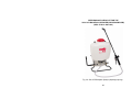
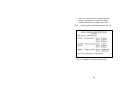
PERFORMANCE CHECKLIST FOR THE
SOLO 475 BACKPACK SPRAYER (DIAPHRAGM PUMP)
(NSN: 3740-01-496-9306)
Fig. 36. Solo 475 Backpack Sprayer (diaphragm pump).
82
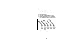
A. Specifications:
• Formulations - Liquids, wettable powders.
• Dry Weight: 9.5 - 10.1 lbs.
• Output: 0.8 U.S. Gallon/min.
• Nozzle, wand & Shut-off Valve (28’ Overall
Length).
• PVC Hose (4’ length).
• Spray Tank - Capacity: 4-gallons (15 liters).
• Nozzles: Different types for spot, narrow, wide
angle, and short/long distance spraying (Fig. 37).
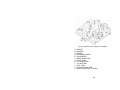
Fig. 37. Solo 475 spray nozzles.
83
SET-UP PROCEDURES FOR THE SOLO 475 (Fig. 36)
1. Removing Plastic Adjustable Nozzle (Fig. 38-1 to
Fig. 38-5).
a. Unscrew the nozzle cap (Fig. 38-1) from the
nozzle body (Fig. 38-3). This is best
accomplished while the retaining nut (Fig. 38-2)
is fastened tightly to the elbow (Fig. 38-5).
b. Unscrew the retaining nut (Fig. 38-2). Push the
nozzle body (Fig. 38-3) out of the retaining nut
(Fig. 38-2). The filter with gasket (Fig. 38-4) will
come out with the body. To reinstall the nozzle,
reverse the above instructions.
Fig. 38. Removing Nozzle.
2. Wand Assembly.
a. Insert wand into shut-off valve as shown (Fig.
39).
84
b. Tighten the screw cap clockwise onto the shut-off
valve (Fig. 39).
Fig. 39. Wand Assembly.
3. Pump Lever
a. Place lever handle (Fig. 40-C) onto the shaft (Fig.
40-A). Align bolt holes and install the two bolts
(Fig. 40-E) and washers (Fig. 40-F); then tighten.
To install pump lever on the opposite side,
remove the stop plate (Fig. 40-D) and washer,
install the pump lever as above. The stop plate
(Fig. 40-D) should be mounted on the inner bolt
hole, with the closed end of the stop plate pointing
downward on the opposite side of the pump shaft.
85
Fig. 40. Pump Lever Assembly.
4. Fold Away Pump Handle
a. .Remove bolt and nut (Fig. 41-A) from pump rod
(Fig. 41-B).
Fig. 41. Pump handle assembly.
86
b. Slide handle-assembly over the pump rod and
align the holes so that the rear (elbow) portion of
the handle points up and slightly forward and
away from the Solo logo. Reinstall bolt and
locknut. Pump handle can be installed on the
opposite side of the sprayer for right hand
pumping (Stop plate will need to be relocated to
the left side) (Fig. 42).
Fig. 42. Pump handle assembly.
c. The handle can be rotated to either down
(pumping) or up (storage) positions. Note: The
handle swings away from the sprayer, then up or
down as desired. The spray wand attaches to the
clamps on the handle assembly for storage (does
not apply to the brass wand) (Fig. 43).
87
Fig. 43. Pump handle assembly.
5. Shoulder Strap Installation. The top of each
shoulder strap is pre-attached to the sprayer by
means of a buckle. The lower end of the straps are
attached by fastening the strap hooks to the metal
frame between where frame exits the plastic tank
and makes a bend.
88
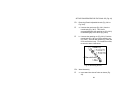
6.
Regulating Pressure. The Solo backpack sprayer
is equipped with a built-in regulator to control
output pressure. This regulator is operator
adjustable. Make adjustments prior to filling tank.
a. To adjust the regulator, remove the tank cap and
the filter basket. Look inside the spray tank; you
will see the top of the regulator. There are 4
fingers on the regulator knob. The finger farthest
to the right is #1; to the left is #4.
b. To increase the pressure, choose the higher
number. They are numbered 1, 2, 3, 4. 1 = 15
psi, 2 = 30 psi, 3 = 45 psi, 4 = 60 psi. The higher
the pressure, the more pesticide applied from the
sprayer in a given amount of time, but the
droplets will be smaller with more drift (Fig. 44).
Fig. 44. Pressure Control Valve.
89
c. To change the spray pressure, excess pressure in
the pressure cylinder must be released back into
the tank through the spray tube. To adjust, push
down on the knob and rotate to align the desired
number with the alignment pin. Note: maximum
pressure for Solo Backpack Sprayer - Model 475
is 60 psi.
7. Filling the Spray Tank.
a. Mix the spray formula and the proper volume of
water in a separate container. Pour the mix
through the filter basket in the tank opening. This
keeps debris from entering sprayer.
b. To fill the sprayer to its full 4-gallon capacity, set
the pressure control valve to the 3 or 4 setting.
c. Add 2 or 3 gallons of pesticide mix, pump the
sprayer handle to prime the pump, and fill the
pressure cylinder. The volume of liquid in formula
the pesticide mix tank will appear to decrease as
the pressure cylinder is filled. Liquid will flow
through the top of the pressure regulator when
the cylinder is completely full.
d. Add the remaining formula mix to the tank.
Remember that it's not necessary to completely
fill the spray tank each time. Mix only the amount
needed to get the job done.
90
PESTICIDE SPRAY OPERATION
8. Prime the pump with rapid pump strokes. When you
feel very firm resistance, the pressure chamber is
filling with liquid. With repeated piston strokes, the
air in the pressure chamber is slowly compressed.
By pressing the hand lever, the valve opens, and
liquid is forced through the nozzle. The shut-off
valve has a retaining clip, which keeps the valve in
the "OPEN" position for continuous operation. Pump
using the end of the pump handle, as it is less
fatiguing. The volume of pesticide delivered varies
with the working pressure. The working pressure
should be as high as needed to ensure an adequate
spray pattern for each individual application. The
well-designed lever action greatly reduces the
pumping effort. The pressure cylinder within the
tank has a hydraulic effect. YOU DO NOT NEED
TO CONSTANTLY PUMP THE PUMP LEVER TO
PRODUCE A STEADY STREAM OF PESTICIDE.
Liquid from the pump compresses air in the pressure
chamber, which allows irregular pumping action, yet
results in steady spray at the nozzle.
9. Should the pressure drop very quickly, drain the tank
completely and pump without liquid. By this
procedure, the air chamber is refilled with the
required volume of air. It is advisable to pump the
tank completely empty from time to time.
91
CLEANING
10. After spraying, clean the tank thoroughly. If some
spray liquid is left inside, drain tank completely.
11. Pumping causes air to be taken in and the remaining
liquid to be discharged. Pump until liquid and air are
coming out through the nozzle.
12. Refill tank with a few quarts of clean water and
pump the water out as explained above (if
necessary, repeat this procedure several times).
13. If the shut-off valve is removed, the pump can be
flushed quickly. Improper spray distribution is the
result of a clogged nozzle, which is easily removed
and cleaned.
14. Soap and water may also be used to clean tank. Do
not use aggressive cleaning agents or abrasives.
Follow the recommendations of the chemical
manufacturer for disposal of waste-water and
chemicals. Activated charcoal in liquid or other form
may be used to absorb chemicals in tanks or spills.
MAINTENANCE AND STORAGE
15. Refill To protect the piston, cylinder and Viton®
collar, a fine mesh, stainless steel screen is located
on the pressure cylinder inlet. If you find that your
sprayer will not empty the formula tank, check for a
clogged inlet screen (Fig. 45). The inlet screen is
located at the bottom of the pressure cylinder on the
92
side that faces your back. One indication that it
needs cleaning is that when you let go of the pump
handle, it "springs" to the down position. The screen
can be cleaned with a small bristle brush or a
discarded toothbrush.
Fig. 45. Solo 475 Backpack Sprayer - Inlet Screen.
16. After operation, the sprayer should be stored away
from direct sunlight to prevent UV damage.
17. After removing the pump or when mounting a new
Viton® collar, treat both the collar and the piston
with water-resistant grease (Solo Superior Grease
(#9850). Petroleum jelly may also be used).
18. Regularly inspect hose, wand, pump, tank and shutoff valve for wear, damage or leaks. Repair
promptly.
93
19. Before winter, drain all liquid in tank, lines and air
chamber. Leave shut-off valve locked in the "open"
position.
CALIBRATION
20. The output of the sprayer should be checked by
collecting and measuring the pesticide emitted
during one minute. Maintain steady pumping on the
pump handle while measuring. Having determined
the output from the nozzle in gallons/minute, the rate
per unit area treated can be calculated knowing the
swath width and walking speed.
21.
Determine the nozzle's rated capacity. See
instruction manual or Solo website:
http://www.solousa.com for all nozzle ratings. Get
the capacity in gallons/minute at the desired
pressure. Test the delivery of the nozzle. Spray
for one minute and collect the spray Fig. 46).
Fig. 46. Calibration - pesticide spray per minute.
22. Compute the area covered in square feet per
minute. Select a comfortable walking speed and
figure how many feet per minute you walk. A
convenient fast walk for some is 2.5 mph, but this
94
may vary. One mile per hour equals 88 feet per
minute. An easy way to calculate is to simply
measure the distance you walk in one minute.
23.
Compute gallons of pesticide per acre (Fig. 47).
Fig. 47. Calibration - pesticide spray per acre.
95
REPAIRS
24. For piston pump, diaphragm pump, pressure
cylinder, shut-off valve, and wand repair see
instruction manual or Solo website:
http://www.solousa.com.
96
SECTION III
HYDRAULIC SPRAYERS
97
PERFORMANCE CHECKLIST FOR THE
FARM TEC MODELATE-20:
20-GALLON HYDRAULIC SPRAYER
Fig. 48. FARM-TEC ATE 20 Hydraulic Sprayer.
SET-UP PROCEDURES FOR THE
FARM TEC ATE-20 (Fig. 48)
1.
Charge up deep-cycle battery overnight with
EXUDE battery charger (12-volt, 6 amp) provided
with sprayer. This should be done the day before
spray operation or every six months of sprayer
storage. Fully charged battery will provide for eight
hours of spray operation.
2.
Check the entire sprayer thoroughly prior to use for
wear areas, tight and clean battery cables
98
(maintenance free battery), cracks in tank, hoses,
pump, filter housing, frame, all hose clamps, etc.
3.
Disconnect and unplug battery charger when
green light is on indicating the battery is fully
charged.
4.
Put 2-3 gallons of water in tank. Connect spray
wand to hose and connect other end of hose (male
end) next to battery case in front of tank.
5.
Select proper TeeJet nozzle required for spray
operation. Turn on toggle switch located on left
side of tank, below the pressure gauge.
Immediately check for leaks. Correct as needed.
OPERATING PROCEDURES
6.
Adjust the working pressure by adjusting T-handle
on top of pump (must loosen lock nut below Thandle first). The proper pressure should be 40
psi. Sprayer should be calibrated to check the flow
rate.
7.
Put on all Personal Protective Gear.
8.
Fill the tank with half of the diluent needed.
Calculate the amount of pesticide needed and add
to the tank. Then add the remainder of the diluent.
(Kerosene or diesel may be added to prevent
foaming of the pesticide).
99
9.
You are now ready to spray! Turn on switch and
re-check the working pressure. Pull the spray
wand trigger to spray.
Terminating Procedures
10.
Drain any remaining pesticide into the proper
container through spray wand or hose located next
to the battery case. NEVER STORE PESTICIDE
IN THE TANK!!!
11.
Flush out tank, hose, and wand by adding 3-5
gallons of water/detergent mixture. This should be
done on spray operation site when possible.
12.
Rinse out system with water. Wash off the exterior
of the sprayer. Air-dry the tank and exterior prior to
storage.
100
PERFORMANCE CHECKLIST FOR THE
HUDSON MODEL 47200 DL SPRAYER
SETUP PROCEDURES
1.
Secure the unit to the truck for towing.
2.
Check the gasoline tank, located on top of the
engine through the hole in the hood, and fill with
regular gas as needed.
3.
Check the oil level by reading the dipstick, located
at the rear of the engine, and fill with 30-weight oil
as needed.
4.
Check the oil level in the pump plug, located on the
right side of the pump, and fill to the threads with
30-weight oil as needed.
5.
Check the belt tension, underneath the machine,
midway between the engine and the pump. A
properly maintained belt should deflect 1/2 to 3/4
inches. (NEVER ATTEMPT TO CHECK THE BELT
TENSION WHILE THE ENGINE IS RUNNING.)
6.
Grease the fitting at the end of the agitator shaft,
located underneath the belt guard, as needed.
7.
Ensure that the inline ratchet type flow valve,
located on top of the surge tank, is parallel to the
ground.
101
8.
Open the gasoline valve located underneath the
gasoline tank.
9.
Using the spray gun, select the proper nozzle disc
(read the pesticide label) and secure it to the spray
gun at the nozzle cap. (Remember: the flow rate of
the disc cannot exceed the capacity of the pump).
10.
Open the pesticide tank cover and clean the
basket filter as needed.
11.
Close the choke, located behind the air filter cover,
by pulling the lever towards the cover. (Omit this
step if the engine is already warm.)
12.
Pull the starter rope firmly until the engine starts.
CAUTION: HEARING PROTECTION REQUIRED.
Return the rope in one smooth motion (i.e., do not
let go of the rope).
13.
As the engine warms up, slowly open the choke.
14.
Put on all personal protective gear.
15.
Fill the pesticide tank with half of the carrier
needed (read the pesticide label), then add the
measured amount of pesticide to bring the solution
up to the label's recommendation and then add the
remainder of the carrier (Adding the pesticide while
the engine is running aids in the mixing of the
material). If using a wettable powder, add 1 pint of
kerosene to every 100 gallons of liquid to inhibit
foaming.
102
16.
Keep track of the pesticide level inside of the tank
by occasionally examining the clear tubing at the
back of the tank.
OPERATING PROCEDURES
17.
Turn the ratchet type flow valve, located on top of
the surge tank, to pressurize the hose and gun.
18.
Adjust the pressure on the gauge to 200 psi by
turning the locking nut, located under the large
spring next to the pump, clockwise.
19.
Unwind the hose from the spindle and examine it
and the connection for leaks.
20.
Point the gun at the intended target area and pull
the trigger. You can adjust the spray pattern by
turning the adjuster located behind the trigger.
TERMINATING PROCEDURES
21.
Discontinue spraying by releasing the spray gun
trigger.
22.
Release the pressure in the hose and spray gun by
turning the ratchet type valve located on top of the
surge tank. Be sure to pull the trigger again to
expel any material that is still in the hose.
23.
Drain remaining pesticide from the tank through
the drain line, located at the bottom, rear of the
tank, into an approved holding tank.
103
24. a. If using water-based pesticides, refill the tank with
enough water and detergent to cleanse the
machinery (not less than 10 gallons). Repressurize the system and flush the material
through the spray gun.
b. If using oil-based pesticides, refill the tank with an
approved flushing solution, and follow the
procedure in step 24a.
25. Secure the hose and spray gun assembly.
26. Close the inline gasoline flow valve, located
underneath the gasoline tank, and let run until
engine dies. This burns the gas out of the
carburetor. There is also a kill button located on the
engine below the carburetor.
27. Prepare the machine for storage by draining off any
excess water or flushing solution from the pesticide
tank and washing down the machine's exterior.
104
PERFORMANCE CHECKLIST FOR
JOHN BEAN HYDRAULIC POWER SPRAYER
MODEL DM10E 150
(NSN: 3740-00-925-9598)
Fig. 49. John Bean Hydraulic Sprayer, Model DM10E 150.
SET-UP PROCEDURES FOR THE JOHN BEAN MODEL
DM10E 150 HYDRAULIC SPRAYER (Fig. 49).
1.
Secure the unit to a truck for towing, safety chain
installed.
2.
Check the gasoline level and fill with regular
unleaded gas as needed.
105
3.
Check the oil level with the engine dipstick located
at rear of engine and fill to full mark on dipstick with
30-weight HD oil.
4.
Check the oil level in the pump, plug located at
right side base of pump and fill to bottom of plug
threads with 30-weight oil.
5.
Check the belt tension midway between the engine
and pump. Properly maintained belts should
deflect 1/2 to 3/4 inches. NEVER ATTEMPT TO
CHECK THE BELTS WHILE THE ENGINE IS
RUNNING.
6.
Grease the two agitator bearing fittings located at
the rear of tank and the right front of tank next to
the pump. Use multipurpose lithium based grease
in a hand operated-gun.
7.
Unscrew and examine the star screen filter and
clean as needed. The filter housing is located
between the engine and pump.
8.
Ensure that the three “inline” valves, located at the
base of the surge tank, adjacent to pressure relief
valve, and on hose reef spindle (yellow handled
lever), are in the OFF position.
9.
Ensure that the pressure relief valve, located
adjacent to the star screen filter housing, is backed
out and then tightened slightly so that it will not fall
out.
106
10.
Open gasoline valve located under the gasoline
tank; right side of the engine.
11.
Close the choke by moving the choke lever up.
(Omit this step if the engine is already warm.)
12.
On a cold engine: place the throttle control midway
between the slow and fast positions.
13.
Pull the starter rope firmly until the engine starts.
CAUTION: HEARING PROTECTION REQUIRED.
Return the rope in one smooth motion, i.e., do not
let go of the rope!!!
14. As the engine warms up, slowly open the choke.
15. Put on all personal protective equipment (PPE).
16. Fill the tank with the carrier needed, read the
pesticide label and then add the measured amount
of pesticide/herbicide to bring the formulation up to
the label's recommendations. (Adding the
pesticide/herbicide, while engine is running, aids
with mixing.) If using wettable powders, add 1 pint of
kerosene to every 100 gallons of formulation in the
tank to inhibit foaming.
17.
Keep track of the level in the tank by occasionally
examining the clear tubing at the left front of the
tank.
107
OPERATING PROCEDURES
18. Using the Spray Gun Assembly
a. Close the pressure relief valve, located until 200
psi reads on the pressure gauge.
b. Unwind the hose from the spindle and examine it
for possible leaks.
c. Open all three inline flow valves to the gun.
d. Point the gun at the intended target area and pull
the trigger. Adjust spray pattern as needed.
19. Using The Boom Assembly
a.
Unhook and GENTLY let down the boom, or
booms (depending on what is required for the
operation).
b. Ensure that both spray gun's inline flow valves
are closed.
c. Select the proper setting on large valve located
on left front of tank to boom or booms needed
(i.e., center-left-right or left-center-right).
d. Turn the pressure relief valve until the pressure
gauge on the boom selector valve reads 40 psi.
This is to be done after turning on the (two) inline
valves located behind the pressure relief valve at
the right front of tank. (i.e., pull top rope forward
108
to turn on pressure and pull bottom rope forward
to turn off).
e. You must lift the lever on front of boom selector
valve to the horizontal position to pressurize the
booms.
f.
The two ropes are there to allow operations to be
conducted from the towing vehicle.
TERMINATING PROCEDURES
20.
21.
22.
Discontinue spraying by either releasing the trigger
on spray gun or pulling the bottom rope toward the
front of the sprayer or tow vehicle.
Open the pressure relief valve to release the
system's pressure.
Drain the pesticide into a holding tank by way of
the drainpipe located to the front and side of the
machine.
CLEANING PROCEDURES
23.
Refill the tank with at least 10 gallons of water and
add some liquid detergent.
24.
Re-pressurize the entire system. Flush out all
spray hose, gun, and nozzle. Flush out entire
boom system through nozzle.
25.
Open the pressure relief valve after all cleaning
solution is used up. Drain all lines. Close all inline
109
valves and place boom selector valve to the A
position (i.e., in front of gauge).
26.
Secure the spray gun into pipe holder, wind-up
hose reel. Secure the boom assembly into bracket
provided.
27.
Close the inline fuel valve located under engine
gas tank.
28.
Drain off any excess water from the tank and let it
air dry.
110
PERFORMANCE CHECKLIST FOR THE
JOHN BEAN PLC MODEL DP05E/30 PRB
HYDRAULIC SPRAYER
SETUP PROCEDURES
1.
Check the entire sprayer thoroughly for any wear
areas, loose parts, and any items, which could
cause problems during operation.
2.
Check oil level in engine, pump, and gearbox. Fill
all three with 30W oil as needed. Fill engine fuel
tank (regular unleaded).
3.
Inspect the tank, filler basket, and suction strainer
for foreign materials. Clean or repair as necessary.
4.
Inspect all hose and piping connections for loose
connections or damage. Repair as necessary.
5.
Check spray gun nozzle disc size for required flow
rate at selected pressure (Check the "pesticide
label" for required flow rate).
6.
Put on all personal protective gear.
7.
Fill the tank with half the diluent needed, calculate
the amount of pesticide required and add to the
tank. Then add the remainder of the diluent.
8.
Secure the pesticide tank cover.
111
OPERATING PROCEDURES
9.
Turn the pressure relief valve lever, located on the
left side of the pump, clockwise (up) to the nonpressure position.
10.
Close the choke, located on the carburetor (under
the air filter) by lifting the lever. Open the choke as
the engine warms up. (Omit this step if the engine
is already warm).
11.
Remove the spark plug ground; pull the starter
rope firmly until engine starts. CAUTION:
HEARING PROTECTION REQUIRED. Throttle
lever (located under the air filter) square rod must
be pulled all the way out.
12.
Turn pressure relief valve down, (counterclockwise). Adjust the pressure- (0-450 psi) when
using hose/spray-gun at 200 psi normally. Open
both inline valves to pressurize.
13.
Conduct the spray operation by pulling the spray
gun trigger. The spray pattern can be adjusted
behind trigger lever.
TERMINATING PROCEDURES
14.
After ceasing spray operations, close both inline
valves first. Release pressure adjusting valve turn
clockwise up to release all pressure. Drain all
pressure out of spray hose. Push sparkplug
ground against sparkplug.
112
15.
Drain any excess pesticide from the tank using the
tank drain (center front of tank bottom). Never use
the pesticide tank as a holding vessel!!!
16.
Replace the drain plug, add water (5 gallons) and
a detergent to the tank, restart, pressurize, and
resume spraying through the spray gun.
17.
Rinse out with clear water, wash off exterior of
sprayer and air-dry tank and exterior.
113
PERFORMANCE CHECKLIST FOR THE
SMITHCO MODEL 6911
100-GALLON HYDRAULIC SPRAYER
SET-UP PROCEDURES
1.
Secure the unit to a truck for towing, safety chain
installed.
2.
Check the gasoline level of the gas tank located on
the left side of the engine and fill with regular
unleaded gas as needed.
3.
Check the engine oil level. The plug is located at
rear of engine. Fill to the bottom of the threads with
30-weight HD oil.
4.
Check the oil level in the pump; the clear plastic site
tube located at the front of the pump should be filled
to half full with 30-weight oil.
5.
Be sure to check charge in pulsation damper
located on top of pump dome. Damper should be
charged with compressed air up to 10% of operating
pressure (200 psi). This ensures smooth operating
pressure of the pump.
6.
Check the belt tension midway between the engine
and pump. Properly maintained belts should deflect
1/
3
2 to /4 inches. NEVER ATTEMPT TO CHECK
THE BELTS WHILE THE ENGINE IS RUNNING.
114
7.
Grease the agitator shaft fitting located at the
agitator shaft flange at the rear of spray tank behind
the pulleys. Use multi-purpose lithium based grease
in a hand-operated gun.
8.
Unscrew and examine the in-line jar-type filter and
clean as needed. The filter housing is located on the
right side of the pump.
9.
Ensure that in-line valves located at the base of the
pump and on the right front part of the tank are in
the OFF position (handle is in cross-line position).
10.
Ensure that the pressure relief valve, located
adjacent to the pump dome, is backed out with the
handle up.
11.
Close the choke by moving the choke lever over to
the CHOKE CLOSE position (Omit this step if the
engine is already warm).
12.
On a cold engine: place the throttle control midway
between the slow and fast positions.
13.
Pull the starter rope firmly until the engine starts.
CAUTION: HEARING PROTECTION REQUIRED.
Return the rope in one smooth motion; DO NOT
LET GO OF THE ROPE!
14.
As the engine warms up, slowly open the choke.
15.
Put on all personal protective equipment (PPE).
115
16.
Fill the tank with the carrier needed, read the
pesticide label and then add the measured amount
of pesticide/herbicide to bring the formulation up to
the label's recommendations (Adding the pesticide/
herbicide, while engine is running, aids with mixing.)
If using wettable powders, ADD 1 PINT OF
KEROSENE TO EVERY 100 GALLONS OF
FORMULATION IN THE TANK TO INHIBIT
FOAMING.
17.
Keep track of the level in the tank by occasionally
examining the clear tube at the left front of the tank.
OPERATING PROCEDURES:
USING THE SPRAY GUN ASSEMBLY
18.
The Locking Clip on the Pressure Control Unit may
be positioned in one of 4 notches in the housing.
This provides 4 different pressure settings when the
lever is pushed down. Select the setting that
provides the correct pressure for your use.
19.
Ensure the pressure gauge reads 200 psi. For fine
adjustments, lift the wire clip off and turn the knurled
thumbnut on the plunger stem. Turn clockwise to
decrease pressure, counter-clockwise to increase
pressure. Engage the lever into one of the 4
available positions in the housing.
20.
Unwind the hose from the spindle and examine it for
possible leaks.
116
21.
Open the inline flow valve to the hose reel. One is
located on the left side of the pump and the other is
on the right, at the front of the spray tank.
22
Point the gun at the intended target area and pull
the trigger. Adjust spray pattern as needed.
TERMINATING PROCEDURES
23.
Discontinue spraying by releasing the trigger on
spray gun.
24.
Open the pressure relief valve by releasing the wire
clip on the Pressure Control Unit.
25.
Drain the pesticide into a holding tank by way of the
drainpipe located at the rear of the sprayer below
the pump. The drainpipe is attached to the frame.
CLEANING PROCEDURES:
26.
Refill the tank with at least 10 gallons of water and
add liquid detergent.
27.
Re-pressurize the entire system. Flush out the spray
hose, gun, and nozzle.
28.
Open the pressure relief valve after all cleaning
solution is used up. Drain all lines. Close all in-line
valves.
29.
Wind up the hose and secure the spray gun.
117
30.
Drain off excess water from the tank and allow the
spray tank to air dry for several days.
118
SECTION IV
VEHICLE MOUNTED
ULV SPRAYERS
119
PERFORMANCE CHECKLIST FOR THE
BEECO PRO-MIST 15MP ULV SPRAYER
(NSN: 3740-01-206-9635)
Fig. 50. BEECO Pro-Mist ULV Sprayer & ATV.
TESTING OF ENVIRONMENTAL CONDITIONS
FOR ULV APPLICATIONS
A.
Check the weather conditions expected during the
spray operation. REMEMBER, YOU SHOULD NOT
CONDUCT OPERATIONS IN THE RAIN OR IN
STRONG WINDS!
B.
Check for a temperature inversion. A temperature
inversion has occurred when the air temperature at
120
six feet above the ground is at least one degree
warmer than the ground temperature. (This situation
usually occurs in the early morning and late evening
hours.)
C. Check the wind speed by using a wind-measuring
device. The indicated wind speed should fall
between 4-6 mph and should be blowing across the
intended target area.
SET-UP PROCEDURES FOR THE BEECO PRO-MIST
ULV SPRAYER (Fig. 50)
1.
Mount the spray unit in the rear of a pickup truck, flat
bed (slightly behind the tailgate) or trailer hitched to
an “All Terrain Vehicle” (ATV; Fig. 33.). (Dry weight
of sprayer is less than battery, approximately 75 lbs.)
2.
Ensure the sprayer is secured to the vehicle by nuts,
bolts and lock washers at all four corners of mounting
beams.
3.
Ensure that the flushing solution tank (smaller tank
location on left side of spray head) is filled with an
approved flushing solution.
OPERATING THE UNIT FROM A VEHICLE'S
ELECTRICAL SYSTEM
4.
a. Verify that the vehicle's alternator rates between
60-80 amperes (amps). This ensures that the
sprayer will maintain a constant speed.
121
b. Ensure sprayer's power-cable lead to the
vehicle's battery is #10 wire. Main system and
motors are protected by circuit breakers; no fuses
are used.
c. CAUTION: Most “tactical vehicles” are 24-volt
systems. Verify cables are only connected to 12volts, not 24-volts.
d. Connect the power cable to the battery (positive
RED CLIP FIRST, negative black clip (ground)
second; use a 12-volt vehicle battery only.
Higher rated 24-volt batteries will cause
permanent damage to the BEECO sprayer.
OPERATING THE UNIT FROM A BATTERY
5.
a. Install a 12-volt battery of at least 70-amp hours
capacity (We strongly recommend the use of a
deep-cycle RV/marine battery with at least 165180 minutes reserve capacity).
(1) The space within the machine's super
structure, under the blower HOUSING, is
designed to hold any size 12-volt battery.
b. Install marine battery terminal onto battery.
c. Hook white wire to positive terminal first, then
black wire to negative terminal; then tighten wing
nuts.
122
(1) A fully charged 12volt deep-cycle battery will
provide 3-4 hours of continuous operation.
SETUP PROCEDURES
6.
FIRST, ENSURE ALL SWITCHES ARE OFF BOTH
INSIDE AND OUTSIDE OF ELECTRICAL BOX!!
Plug the control cable into the back of the operator
control box at one end, and into the bottom of the
breaker module inside the electrical control box.
7.
Check:
a. All electrical cables and connections are secure
and clean.
b. The battery is in good condition.
c. Charge the vehicle's alternator between 13.8 and
14.8 volts (if you are going to connect the sprayer
to the vehicle’s electrical system).
d. The insecticide delivery system to ensure that all
tubing is securely connected, the filter is tight,
and quick-fittings are latched.
e. Ensure that the end of the pickup tube in the
insecticide tank extends to the bottom of the
insecticide tank.
8.
Put on all personal protective equipment.
123
9.
Add liquid to the insecticide tank. Use the 5-gallon
polyethylene plastic tank strapped down behind the
spray head assembly. Use EPA approved ULV
concentrates only. Cautionary Note: No insecticide
spraying should be performed until the pump has
been calibrated.
CALIBRATION PROCEDURES
10. Disconnect the insecticide tube at the spray head,
just below the blower housing, and place the tube
into an empty container.
11. Slightly loosen the two knurled knob lock nuts that
secure the pump's pointer, located next to the
electrical box.
12. Set the pointer at an arbitrary number of 0-10 in the
direction of flow, by rotating the black knob, located
next to the pump numbers.
13. Turn on the main breaker located on the outside of
the electrical box on the left side. Also turn on the
pump circuit breaker located inside the box.
14. Depress and hold down the calibration button inside
the electrical box until the insecticide flows without
air bubbles in the line. Release the button and hold
the tube up.
15. a. Hold the open end of the insecticide tube above
the graduated cylinder.
124
b. Depress the calibration button.
c. Put tube into graduated cylinder at the same
time.
d. Hold for one minute.
e. Check the flow rate and adjust the pump as
needed. (Flow rate is found on the pesticide
label.)
f.
Recheck for one minute.
16. Turn on all switches.
a. First turn on circuit breaker located on the outside
of the electrical control box. (Located next to the
hour meter.)
b. Blower Circuit breakers for the blower, spray
head, and pump are located inside of the
electrical control box.
17. Depress the power switch, located on remote control
panel.
a. The switch indicator light will illuminate and the
fan and spray head will start. The spray head will
run at idle speed (about 15,000 rpm).
b. The spray head will accelerate to its spraying
speed and the blower will start.
125
18. Check volt lights located on the remote control
panel. Ensure 12volt green light is on. If not, recheck
cable hookup at battery.
19. YOU ARE NOW READY FOR SPRAYING.
20. Depress spray switch and the pump will deliver the
insecticide.
21. Check volt and alert lights on remote control box for
proper operation (Green light for volts, and no lights
on for alert).
a. If at any time during operation the sleeve does
not rotate fast enough to properly spray, the
controller will automatically prevent the pump
from operating.
b. AVOID TURNING ON ANY OTHER
ELECTRICAL PULLS (LIGHTS, RADIO, ETC.)
CONNECTED TO THE VEHICLE'S BATTERY.
TERMINATING PROCEDURES
22. Depress the spray switch.
a. The pump will stop.
b. The blower and spray head will continue to
operate.
126
23.
Allow the sleeve to spin at idle speed for a minute
or so after the pump is shut off to remove the
remaining insecticide.
24.
For emergency shutoff, depress "off" button on
remote panel to trip main circuit breaker. To
restart, turn the main breaker back on.
127
FLUSHING
25. It is recommended that you begin flushing the tank
during your final spray run AT THE JOB SITE.
26. Depress power switch.
27. Depress flush switch.
a. An audible alarm will sound to indicate flushing
has begun.
28. Run the system for 5 minutes at a flow rate of 3 oz
per minute.
29.
After the lines are free of insecticide, turn the pump
flow rate to 12-15 oz per minute and run the
flushing solvent through the system for one minute.
30. Turn off the flush switch and power switch.
CLEANING PROCEDURES
31. BEFORE CLEANING: Disconnect the negative
battery cable from the sprayer. Cover the ceramic
spray head sleeve with a plastic bag and rubber
band.
32. Completely wipe down the exterior of the machine
with a spray on/wipe off cleaning solution (GP
Cleaner, 409, or Isopropyl Alcohol).
128
33. Avoid getting any water on the electrical connections
and sleeve assembly.
34. When you are done cleaning, dry off the system.
(Compressed air on all electrical terminals works
best.)
35. Turn the pump pointer so that the pesticide flow is
reversed-going INTO the pesticide tank.
36. Depress power and spray button. This will dry the
sleeve and suck pesticide from lines into pesticide
tank.
37. Depress power and spray button to shut off.
38. Reset pump pointer to "0".
39. Remove the pickup line from the pesticide tank and
secure any remaining pesticide into its original
container.
40. Turn all switches off, both inside and outside of
electrical box.
41. Store the unit under proper cover, keep dry.
129
PERFORMANCE CHECKLIST FOR THE
CURTIS MODEL 2740 ULV SPRAYER
(NSN: 3740-01-141-2557)
TESTING OF ENVIRONMENTAL CONDITIONS
FOR ULV APPLICATIONS
A.
Check the weather conditions expected during the
spray operations. REMEMBER, YOU SHOULD NOT
CONDUCT ULV OPERATIONS IN THE RAIN OR IN
STRONG WINDS.
B.
Check for a temperature inversion. A temperature
inversion has occurred when the air temperature at
six feet above the ground is at least one degree
warmer than the ground temperature. This situation
usually occurs in the early morning and late evening
hours.
C. Check the wind speed by using a wind-measuring
device. The ideal indicated wind speed should fall
between 4-6 mph and should be blowing across the
intended target area. No spraying if wind is 10 mph
or greater.
SET-UP PROCEDURES
1.
Place the ULV unit in a pickup truck or on a trailer
and secure it for towing.
2.
Check the fuel level of the Fuel Tank. Add regular
unleaded gas as needed. Fuel Tank is located on
right side of engine (black polyethylene tank).
130
3.
Check the engine Oil Level using the dipstick
located on left side of engine below the Air Filter (It
is marked “Oil”). Add SAE 30-weight detergent oil
as needed.
4.
Check the Blower Oil level. The plug is located on
the side closest to the drain plug. Fill through the
Breather Plug at the top, until the oil runs out of the
overflow hole at the side of the blower; close with
plug. You must use 40-weight NON-DETERGENT
oil as needed.
5.
Periodically grease the two fittings, located on
Blower behind the engine.
6.
Check the battery water level. Add water to the
proper level. Periodically, charge the battery.
7.
Ensure that the sprayer Battery Cables are clean
and tight.
8.
Check the Flushing Solution level in the one-gallon
tank mounted on the Formulation Tank bracket and
fill the tank with an approved flushing solution.
Diesel fuel or transmission fluid can be used as
alternatives.
9.
Close the Choke located under the Air Filter
Housing (front of engine) by pulling out the ring.
Omit this step if engine is warm.
10.
Note: OPEN Choke as needed AFTER engine
starts.
131
11.
The Engine Speed Control Slide Ring is located
under the Air Filter Housing on the left side of
engine. Pull ring halfway out.
12.
Ensure all Remote Control switches are in the
“OFF” position.
13.
Plug one end of the Remote Control Cable into the
back side of the Pump Assembly.
14.
Plug the other end of the Remote Control Cable
into the base of the Remote Control Box.
15.
a. The Starter Solenoid Switch is located on the
right side of the engine. Place it into the ON
position.
b. Place the Machine Switch on the Control Box
into the “On” position.
c. Push the Start Switch on the Control Box for a
maximum of 15 seconds. CAUTION: HEARING
PROTECTION REQUIRED. Note: optional
Starter Button located on the right side of the
Engine Air Filter can also be used.
16.
Engine starts.
17.
The Boom Pressure Gauge is located between the
Engine and the Blower. Pressure should read 6
psi. (pressure may vary slightly due to viscosity of
formulation)
132
OPERATING PROCEDURES
18.
Adjust Air Pressure by pulling OUT or pushing IN
the Engine Speed Control Ring on left side of
engine.
19.
Put on all Personal Protective Equipment.
20.
Add the calculated amount of pesticide to the 12gallon polyethylene tank located on the right rear
of the unit. (Remember, Ultra Low Volume (ULV)
and Ultra Low Density (ULD) machines use only
concentrated liquid formulations).
21.
a. Place Function Select Dial on the Remote
Control Box to #1-#4 position as required. (See
page 23 of Owners Manual)
b. Unlock Flow Rate Knob locking ring and adjust
to desired flow rate IAW Pesticide Label.
c. “High-Low” Range Control Switch on the side of
Pump Assembly is in the High position (See
page 23 of Owners Manual).
22.
You are now ready for ULV spraying.
23.
The rate of vehicle speed during the spray
operation is 5 OR 10 mph. The correct speed for
each type pesticide is indicated on the Pesticide
Label.
133
24.
When stopping for a short period of time, turn the
Remote Control Output Switch to the OFF position.
25.
After completing spray operation, with the engine
still running, turn the Flush/Spray Solenoid Switch
on the Remote Control Box to “FLUSH” for two (2)
minutes at 10 ounces per minute.
26.
Place the Output Switch on the Remote Control
Box in the “OFF” Position.
27.
Turn all switches on the Remote Control Box to
“OFF” position. (i.e. Machine and Output)
CALIBRATION PROCEDURES
28.
For ULV calibration, carry out steps 1-22.
29.
Place Function Selector Dial in the #2 position.
Adjust flow rate to desired flow (4 oz, 6 oz, 8 oz,
etc.).
30.
Place Solenoid Switch on Remote Control Box to
“SPRAY” position.
31.
Place HIGH/LOW Selector Switch in the “HIGH”
position.
32.
Disconnect ¼ inch formulation line from the “T” on
the Spray Boom and place into a “pesticide only”
receptacle. Always use a suitable collection
container for pesticide measurement.
134
33.
Place the Output Switch on the Remote Control in
the “ON” position (fluid will begin to flow).
34.
Adjust the Flow Rate Knob on the Remote Control
Box to the desired rate.
35.
The timing person signals the beginning and the
end of the one (1) minute collection period.
36.
Collect sample and compare actual output with
desired output indicated by Remote Control Box
digital read-out.
37.
If sample is NOT within 20% of the volume given
by the Remote Control Box digital read-out, contact
manufacturer or NDVECC, Bangor.
TERMINATING PROCEDURES
38.
After flushing entire system, wash or steam clean
outside of ULV machine with liquid soap and water.
Note: get no water on Remote Control Box.
39.
Break connection at Fuel Tank/Fuel Line junction
and restart Engine to drain the Carburetor prior to
storage.
40.
Keep sprayer under suitable cover and out of
weather.
135
PERFORMANCE CHECKLIST FOR THE
CURTIS MODEL 2742 ULV SPRAYER
TESTING OF ENVIRONMENTAL CONDITIONS
FOR ULV APPLICATIONS:
A.
Check the weather conditions expected during the
spray operations. REMEMBER, YOU SHOULD
NOT CONDUCT ULV OPERATIONS IN THE RAIN
OR IN STRONG WINDS.
B.
Check for a temperature inversion. A temperature
inversion has occurred when the air temperature at
six feet above the ground is at least one degree
warmer than the ground temperature. This
situation usually occurs in the early morning and
late evening hours.
C.
Check the wind speed by using a wind-measuring
device. The ideal indicated wind speed should fall
between 4-6 MPH and should be blowing across
the intended target area. No spraying if wind is 10
mph or greater
SET-UP PROCEDURES:
1.
Place the ULV unit in a pickup truck or on a trailer
and secure it for towing.
2.
Check the fuel level of the Fuel Tank. Add enough
gasoline (approx 1 gal) to submerge the pick up
tube.
136
3.
Check the engine Oil Level using the dipstick
located on left side of engine below the Air Filter (It
is marked “Oil”). Add SAE 30 weight detergent oil
as needed.
4.
Check the Blower Oil level. The plug is located on
the side closest to the drain plug. Fill through the
Breather Plug at the top, until the oil runs out of the
overflow hole at the side of the blower; close with
plug. You must use 40-weight NON-DETERGENT
oil as needed. (9150-01-293-2773).
5.
Periodically grease the two fittings, located on
Blower behind the engine.
6.
Check the Battery water level. Add water to the
proper level. Periodically charge the Battery.
7.
Ensure that the sprayer Battery Cables are clean
and tight.
8.
Check the flushing solution level in the one-gallon
tank mounted on the gas tank bracket and fill the
tank with an approved flushing solution. Diesel
fuel or transmission fluid can be used as
alternatives.
9.
Close the Choke located under the Air Filter
Housing (front of engine) by pulling out the ring.
Omit this step if engine is warm.
10.
Note: OPEN Choke as needed AFTER engine
starts.
137
11.
The Engine Speed Control Slide Ring is located
under the Air Filter Housing on the left side of
engine. Pull ring halfway out.
12.
Ensure all Remote Control Box switches are in the
“OFF” position.
13.
Plug one end of the Remote Control Cable into the
side of the Pump Assembly.
14.
Plug the other end of the Remote Control Cable
into the base of the Remote Control Box.
15.
a. The Starter Solenoid Switch is located on the
right side of the engine. Place it into the ON
position.
b. Place the Machine Switch on the Control Box
into the ON position.
c. Push the Start Switch on the Control Box for a
maximum of 15 seconds. CAUTION: HEARING
PROTECTION REQUIRED. Optional: Starter
Button located right side of Engine below Air
Filter can also be used.
16.
Engine starts.
17.
The Boom Pressure Gauge is located between the
Engine and the Blower. Pressure should read 6
psi (pressure may vary slightly due to viscosity of
formulation).
138
OPERATING PROCEDURES
18.
Adjust Air Pressure by pulling OUT or pushing IN
the Engine Speed Control Ring on left side of
engine.
19.
Put on all Personal Protective Equipment.
20.
Add the calculated amount of pesticide to the 12gallon polyethylene tank located on the right rear of
the unit. (Remember, ULV/ULD machines use
only concentrated liquid formulations).
21.
Place Function Select Dial on the Remote Control
Box to #1 - #4 position as required. (See page 23
of Owners Manual)
22.
You are now ready for ULV spraying.
23.
The rate of vehicle speed during the spray
operation is 5 OR 10 mph. The correct speed for
each type pesticide is indicated on the Pesticide
Label.
24.
When stopping for a short period of time, turn the
Remote Control Output Switch to the OFF position.
25.
After completing spray operation, with the engine
still running, turn the Flush/Spray Solenoid Switch
on the Remote Control Box to “FLUSH” for two (2)
minutes at 10 ounces per minute.
139
26.
Place the Output Switch on the Remote Control
Box in the “OFF” Position.
27.
Turn all switches on the Remote Control Box to
“OFF” position. (i.e. Machine and Output)
CALIBRATION PROCEDURES
28. For ULV calibration, carry out steps 1-22.
29.
Place Function Selector Dial in the #2 position.
Adjust flow rate to desired flow (4 oz, 6 oz, 8 oz,
etc.).
30.
Place Solenoid Switch on Remote Control Box to
“SPRAY” position.
31.
Place HIGH/LOW Selector Switch in the “HIGH”
position.
32.
Disconnect ¼ inch formulation line from the “T” on
the Spray Boom and place into a “pesticide only”
receptacle. Always use a suitable collection
container for pesticide measurement.
33.
Place the Output Switch on the Remote Control in
the “ON” position (fluid will begin to flow).
34.
Adjust the Flow Rate Knob on the Remote Control
Box to the desired rate.
35.
The timing person signals the beginning and the
end of the one (1) minute collection period.
140
36.
Collect sample and compare actual output with
desired output indicated by Remote Control Box
digital read-out.
37.
If sample is NOT within 20% of the volume given
by the Remote Control Box digital read-out, contact
manufacturer or NDVECC, Bangor.
TERMINATING PROCEDURES
1.
After flushing entire system, wash or steam clean
outside of ULV machine with liquid soap and water.
NOTE: Don’t get any water on the Remote Control
Box.
2.
Break connection at Fuel Tank/Fuel Line junction
and restart Engine to drain the Carburetor prior to
storage.
3.
Keep sprayer under suitable cover and out of
weather.
141
PERFORMANCE CHECKLIST FOR THE
CURTIS MODEL 2952 ULV SPRAYER
TESTING OF ENVIRONMENTAL CONDITIONS
FOR ULV APPLICATIONS
A.
Check the weather conditions expected during the
spray operations. REMEMBER, YOU SHOULD
NOT CONDUCT ULV OPERATIONS IN THE RAIN
OR IN STRONG WINDS.
B.
Check for a temperature inversion. A temperature
in- version has occurred when the air temperature at
six feet above the ground is at least one degree
warmer than the ground temperature (This situation
usually occurs in the early morning and late evening
hours).
C. Check the wind speed by using a wind-measuring
device. The indicated wind speed should fall
between 4-6 mph and should be blowing across the
intended target area.
SETUP PROCEDURES
1.
Place the ULV on a truck or trailer and secure it for
towing.
2.
Check the fuel level. Add regular unleaded gas as
needed to the large red polyethylene tank.
142
3.
Check the engine oil level using the dipstick,
located at the rear of the engine, near the top. Add
30W oil, as needed.
4.
Check the blower oil level. Plug is located on the
left side closest to the drain plug. Fill through the
breather plug on the top, until the oil reaches the
bottom of the overflow outlet. (Do not remove the
upper plug on the side near the breather plug.)
Add 40W non-detergent oil, as needed.
5.
Periodically, grease the two fittings, located behind
the blower and above the driver shaft. Regular
chassis grease can be used.
6.
Check the battery fluid level. Add water to cover
the cells, continuing to fill to a level where the fluid
reaches the plastic at the opening.
7.
Ensure battery cables are clean and tightly
connected.
8.
Check the flushing solution level in the one-gallon
tank, located on the right side of the battery. Fill as
needed.
9.
Open the air vent, located on top of the fuel tank
near the gas gauge.
10.
Close the choke, located under the engine air filter,
by pulling out the knob. (Omit this step if the
engine is already warm.)
143
11.
Place remote control unit in an area where it will
not be damaged by the vibration of the motor, and
yet will be accessible to the operator.
12.
Ensure that the engine ignition switch, formulation
control switch, and remote control switches are in
the “OFF” position.
13.
Plug the remote control line into the right side of
the pump control box. Plug the other end of the
cable into the base of the remote control box.
14.
Put on all personal protective equipment.
15.
Add the calculated amount of pesticide to the 12gallon polyethylene tank, located on the right rear
of the unit. (Remember, Ultra Low Volume (ULV)
and Ultra Low Density (ULD) machines use only
concentrated liquid formulations.)
START-UP PROCEDURES
16.
Place the "MACHINE" switch on the remote control
box in the ON position.
17.
Place the ON/OFF switch on the top of the engine
in the “ON” position.
18.
Press the starter button located between the
engine and the battery. (Hold until the motor turns
over, not more than 15 seconds.) CAUTION:
HEARING PROTECTION REQUIRED.
144
19.
As the engine starts, gradually push in choke.
(Omit this step if the engine is already warm.)
OPERATING PROCEDURES
20.
Check the boom pressure gauge located below the
formulation selector valve. (Should be at 10 psi for
standard use.)
21.
Adjust air pressure by increasing or decreasing
engine speed with the manual friction slide control
lever located beneath the choke knob.
22.
Place formulation selector switch on the control
box to "SPRAY."
23.
Turn formulation selector valve to "SPRAY."
24.
Place the output switch on the remote control in
the "ON" position.
25.
Select pesticide output, using the pesticide label,
with coarse flow rate knob on control box.
Numbered 1-4.
26.
Loosen lock nut below fine flow rate knob on
control box.
27.
Set precise pesticide flow rate.
28.
Tighten lock nut.
29.
You are now ready for ULV spraying.
145
30.
The rate of vehicle speed during the spray
operation is generally 5 or 10 mph. The correct
speed for each type of pesticide is indicated on the
pesticide label.
31.
When stopping for a short period of time, turn the
remote control output switch to the OFF position.
TERMINATING PROCEDURES
32.
After completing your spray operation, with the
engine still running, turn the formulation selector
valve, located below the flushing solution tank, to
the "FLUSH" position.
33.
Place the switch on the remote control in the
"FLUSH" position.
34.
Place the output switch on the remote control in
the "ON" position.
35.
Set the flow rate on the remote control digital readout to 10 oz/min and flush system for 2-3 min.
36.
Turn all switches to the "OFF" position (Ignition,
formulation valve, and remote control switches).
CALIBRATION PROCEDURES
37.
For ULV calibration, carry out steps 1-22.
38.
Move the formulation selector valve, located below
the solution tank, to the "SPRAY" position.
146
39.
Move the high/low selector switch (near the remote
cable hookup point) to the "HIGH" position.
40.
Disconnect 1/4 inch formulation line from the "T" on
the spray boom and place into a "pesticide only"
bucket. Use a suitable collection container for
actual pesticide measurement.
41.
Move the function select switch on the remote
control to the "#2" position.
42.
Place the mode switch on the remote control in the
"SPRAY" position.
43.
Place the output switch on the remote control in
the "ON" position (fluid will begin to flow).
44.
Adjust the flow rate knob on the remote control to
the desired level.
45.
Have the timing person signal the beginning and
the end of the one-minute collection period.
46.
Collect sample and compare actual output with
output indicated by remote control digital readout.
47.
If the sample is not within 20% of the volume given
by the remote control digital readout, then contact
the manufacturer, NDVECC or a NEPMU.
147
PERFORMANCE CHECKLIST FOR THE
CLARKE (LECO) GRIZZLY ULV SPRAYER
(NSN: 3740-00-375-9154)
Fig. 51. Clarke (LECO) Grizzly ULV Sprayer.
TESTING OF ENVIRONMENTAL CONDITIONS
FOR ULV APPLICATIONS
A.
Check the weather conditions expected during
the spray operations. REMEMBER, YOU
SHOULD NOT CONDUCT ULV OPERATIONS
IN THE RAIN OR IN STRONG WINDS.
B.
Check for a temperature inversion. A
temperature inversion has occurred when the air
temperature at six feet above the ground is at
least one degree warmer than the ground
148
temperature. This situation usually occurs in the
early morning and late evening hours.
C.
Check the wind speed by using a windmeasuring device. The ideal indicated wind
speed should fall between 4-6 mph and should
be blowing across the intended target area. No
spraying if wind is 10 mph or greater.
D.
Before attempting to operate the unit for the first
time, study the complete Instruction Manual
carefully and identify all of the components in
Figs. 51, 52.
149
Fig. 52. Clarke (LECO) Grizzly ULV Sprayer.
A:
B:
C:
D:
E:
F:
G:
H:
I:
J:
K:
L:
ENGINE
BLOWER
NOZZLE
PRESSURE GUAGE
HOUR METER
INSECTICIDE TANK
FLUSH TANK
FILTER SYSTEM
12-V BATTERY
FUEL TANK
FLOW CONTROL BOX
REMOTE CONTROL STATION
150
SET-UP PROCEDURES FOR THE
CLARKE (LECO) GRIZZLY ULV SPRAYER (Fig. 51).
1.
Plug the Remote Control Station Cable Plug into the
socket located on the rear Coupling Cover Panel,
right rear of engine. Be sure to hand tighten the
knurled locking cap onto the socket. (ALL
SWITCHES IN THE OFF POSITION) (Fig. 53).
Fig. 53. Remote Control Station Cable Plug.
151
2.
Mount the Grizzly ULV Fog Generator into a vehicle
or onto a trailer. Unit should be secured to the bed
of the Vehicle.
3.
Remote Control Station - contains a number of
components for controlling the unit (Fig. 54).
Fig. 54. Remote Control Station.
152
PRE-START OPERATING INSTRUCTIONS
4.
Make sure that all switches are in the OFF position.
5.
Verify that the battery cable connections are correct
and tight. Red to positive/black to negative. Check
battery water level if not a maintenance free battery.
6.
Verify that no foreign objects or tools have been left
in or about the fog generator.
7.
Check the oil level in the engine using the dipstick
located on the left side of the engine below the air
filter. Add SAE 30 weight detergent oil (Fig. 55).
Fig. 55. Engine oil level check & fill.
153
8.
Check the blower oil level at the oil overflow plug.
The plug is located on the left side closest to the
drain plug. Fill through the “breather plug” at the
top, until the oil runs out the oil overflow hole at the
side of the blower and then reinstall the plug. You
must use M-S type SAE 40 weight heavy-duty type
from 30 degrees Fahrenheit to 90 degrees
Fahrenheit ambient temperature. DO NOT USE
MULTIPLE VISCOSITY OILS, (Fig. 56).
Fig. 56. Blower oil level check & fill.
9.
Periodically grease the two fittings on the engine
side of the blower, every 50 hours.
154
10. Check the fuel level in the red, nine gallon FUEL
TANK, (Fig. 57). Add regular unleaded fuel as
needed, making sure you cover the pick-up tube.
Fig. 57. Fuel level check & fill.
11. PUT ON ALL PERSONAL PROTECTIVE
EQUIPMENT. Use a screened funnel.
155
12. Add the proper amount of pesticide to the 15 gallon,
black polyethylene tank located between the engine
and gas tank, (Fig. 58) (Remember to use ULV/ULD
machine labeled concentrates ONLY).
Fig. 58. Adding pesticide.
156
13. Place flushing solution in the clear plastic 1-gallon
tank located on the base plate between the blower
and the PDS flow control box. Diesel fuel or
transmission fluid can be used as alternatives, (Fig.
59).
Fig. 59. Adding flushing solution.
14. Verify that the Remote Control Station is within easy
reach of the operator. Make sure control cable is
routed away from moving or hot parts to avoid
damage.
157
15. Verify that the nozzle is in the correct position for
spraying (0O - 45 OF) (Fig. 60).
Fig. 60. Adjusting spray-head angle.
158
START-UP OPERATION
Fig. 61. Remote Control Station.
16. On the Remote Control Station (Fig. 59):
a. Turn the Main Power switch to the ON position.
b. Set the spray on/off switch to the OFF position.
c. Set the spray/flush switch to spray.
159
d. For a cold engine, on the Remote Station,
depress the choke button and starter button at
the same time, until the engine fires. Do not push
buttons for more than a maximum of 15
seconds/minute. CAUTION: HEARING
PROTECTION REQUIRED.
e. For a hot engine, depress the starter button until
the engine fires.
f.
When the engine fires release the choke and
starter buttons (Note: Pressing the starter button
on the engine will also start the engine. The
main power switch on the Remote Control Station
must be in the “ON” position for the engine to be
started).
HOUR METERS
17. The hour meter (on the Fog Generator) mounted
above the pressure gauge between engine and
blower records the engine-blower RPM when the
engine is running and the total engine-blower run
time for service/maintenance and security when the
engine is not running.
18. The hour meter mounted on the Remote Control
Station records the time the ULV spray nozzle is
turned on.
160
OPERATING INSTRUCTIONS:
THE PRESSURE GAUGE
19. The unit is equipped with a glycerin filled pressure
gauge to read the nozzle air pressure and is
mounted on the fog generator coupling guard
between the engine and blower.
ADJUSTING THE NOZZLE AIR PRESSURE
20. Nozzle air pressure is one of the main criteria for
good particle size. Changing the speed of the
engine adjusts this pressure. The nozzle air
pressure can be adjusted by checking the pressure
gauge as the engine speed is increased or
decreased using the large silver hex nut under the
carburetor air filter. This large hex nut adjusts the
governor control and should be turned in small
amounts only after the engine has reached normal
operation temperature. NORMAL AIR PRESSURE
is 6 psi.
LOW-PRESSURE CUT-OFF
21. The Clarke Grizzly Cold Aerosol Fog Generator is
equipped with an air low-pressure cut-off switch. If, for
some reason, the nozzle air pressure drops below 1 psi,
the Flow Control will cut off. This prevents the blower from
being filled with insecticide because of insufficient air blast.
Because of this, the engine on the fog generator must be
running when setting the flow rate.
161
22. The air low-pressure cut-off switch is located inside
the coupling guard and is mounted on the rear of the
pressure gauge. If necessary, this switch can be
adjusted in the field by removing the rubber plug
from the tip of the switch and then using a 7/32”
Allen wrench, turn the adjustment screw in about ½
turn increments. Turning clockwise increases the air
pressure cut-off point. Turning counter-clockwise
decreases the air pressure cut-off point.
SETTING THE FLOW RATE
23. With the engine running, open the cover of the flow
control box.
24. Loosen the pump pointer locking plate by loosening
the two round knurled knobs, one on each side of
the locking plate. Loosen only enough to move the
pointer. The pointer should be moved against a
slight pressure.
25. Turn the black knob on the side of the pump to
increase or decrease the flow setting. The flow
scale is an arbitrary scale and is marked from 0-10
(zero to ten), which represents 0-100% of flow rate.
26. Set the flow rate by following the instructions in the
CALIBRATION section on page 19 of the instruction
manual. The correct flow rate, along with correct
nozzle pressure, is one of the main criteria for good
particle size. Always retighten the knurled knobs
before checking the flow rate, as a loose pointer will
162
affect the pump accuracy. This procedure is
necessary only on the initial setting of a flow rate.
27. NOTE: Unit should be calibrated upon first time set
up of the machine, beginning of each spray season,
when changing insecticides, every 25 hours of
operation, and after conducting any major overhaul.
AUTOMATIC ENGINE IDLE-BACK
28. The CLARKE Grizzly Cold Aerosol Fog Generator is
equipped with engine idle-back. This device
reduces the engine speed to idle when not spraying.
When the Spray switch is turned on, the engine
speed increases to produce the pre-set pressure at
the nozzle.
29. NOTE: Allow the engine to warm up before turning
the Spray switch ON. A cold engine may stall when
the Spray switch is turned ON.
SPRAYING
30. To turn spray on:
a. On the Remote Control Station, move the Select
Spray/Flush switch to SPRAY.
b. Move the spray switch to ON position. Note that
the red indicator light will be on when the spray is
turned on and the engine speed will increase.
163
31. With the unit spraying, check to make sure the
nozzle air pressure is within the preset pressure
range. The Clarke Grizzly Cold Aerosol Fog
Generator is preset at the factory at 6 psi. If a
different nozzle pressure is required, change the
engine speed by adjusting the engine throttle.
32. To turn spray off:
a. On the Remote Control Station, turn the spray off
by moving the spray switch to the OFF position.
The red light will go out and the engine speed will
reduce to idle.
33. NOTE: On the initial start, it may take several
seconds for the insecticide to move from the
insecticide tank, fill the lines and start spraying. This
is normal.
FLUSHING
34. It is absolutely necessary to use a flushing solution
that will cut your insecticide. Do NOT use diesel oil
as a flushing solution.
35. It is a simple matter to flush the system as follows:
a. If the engine is not running, start the engine as
explained in the START-UP section.
b. On the Remote Control Station, set Select
Spray/Flush switch to FLUSH.
164
c. Turn the Spray switch ON. When the flushing
solution starts spraying from the nozzle, spray for
2 to 3 minutes. This is ample time to flush the
system.
d. Turn the Spray switch OFF. It is highly
recommended that the fog generator be shut
down immediately after flushing to prevent
insecticide from being accidentally drawn into the
system.
SHUT-DOWN
36. Before shutting down the engine, be sure the spray
is turned off as explained in the SPRAYING section.
37. To stop the engine, on the Remote Control Station,
move the Main Power switch to the OFF position.
38. After stopping the engine, place the Select
Spray/Flush switch on the Remote Control Station to
Spray.
39. The fog generator is now ready for spraying the next
time it is used. Depressing the emergency stop
switch on the engine will also stop the engine.
165
PERFORMANCE CHECKLIST FOR THE
LECO MODEL 800 ULV SPRAYER
TESTING OF ENVIRONMENTAL CONDITIONS
FOR ULV APPLICATIONS
A.
Check the weather conditions expected during the
spray operations. REMEMBER, YOU SHOULD NOT
CONDUCT ULV OPERATIONS IN THE RAIN OR IN
STRONG WINDS.
B.
Check for a temperature inversion. A temperature
inversion has occurred when the air temperature at
six feet above the ground is at least one degree
warmer than the ground temperature. This situation
usually occurs in the early morning and late evening
hours.
C.
Check the wind speed by using a wind-measuring
device. The indicated wind speed should fall
between 4-6 MPH and should be blowing across the
intended target area.
SET-UP PROCEDURES
1.
Place the ULV unit in a pickup truck or on a trailer
and secure it for towing.
2.
Check the fuel level of the gas tank, mounted on
the engine. Add regular unleaded gas as needed.
166
3.
Check the engine oil level using the dipstick
located at the rear of the engine. Add SAE 30
weight detergent oil as needed.
4.
Check the blower oil level. The plug is located on
the side closest to the drain plug. Fill through the
breather plug at the top, until the oil runs out of the
overflow hole at the side of the blower; close with
the oil plug. You must use 40-weight NONDETERGENT oil as needed.
5.
Periodically grease the two fittings, located behind
the engine, with chassis grease on the blower.
6.
Check the battery water level. Add water to the
proper level. Periodically charge the battery.
7.
Ensure that the sprayer battery cables are clean
and tightly connected.
8.
Check the flushing solution level and fill the tank as
needed with an approved flushing solution. This
clear plastic tank has a one-gallon capacity and is
located behind the lab pump (gray box).
9.
Open the in-line gasoline control valve located
under the gasoline tank.
10.
Close the choke, located to the left of the fan
shroud and to the right of the air filter, by moving
the lever to the choke position (to the left). Omit
this step if the engine is already warm.
167
11.
Move the throttle lever located below the choke
lever to the fast position (UP).
12.
Turn both the light and fog switches located on the
front of the pump box to the OFF positions. Move
the toggle switch located on the remote operator’s
station to the OFF position.
13.
Put on all personal protective gear.
14.
Add the calculated amount of pesticide to the 15gallon black polyethylene insecticide tank located
behind the pump box and to the right of the engine.
REMEMBER, ULV/ULD machines use only ULV
concentrated liquid formulations.
15.
Place the toggle switch located on the frame below
the front of the engine to the on position (UP).
16.
Push the starter button located next to the #15
toggle for a maximum 15 seconds/minute or until
the engine starts. CAUTION: HEARING
PROTECTION REQUIRED.
17.
As the engine warms up, slowly open the choke (to
the Right).
OPERATING PROCEDURES
18.
Check the blower pressure gauge located on the
right side of the flow control (pump box) system by
temporarily holding your finger over the opening in
the plastic fitting to the right of the air gauge.
168
19.
Pressure should read 6 psi. If not, readjust the
engine RPM by moving the throttle lever up or
down. Check the RPM meter located on the frame
below the throttle lever.
Turn the FLUID SELECTOR VALVE to the FOG
position.
20.
YOU ARE NOW READY FOR THE ULV
APPLICATION.
21.
Before attempting to calibrate, remove the
pesticide line at the nozzle and place it into a
suitable empty container. With your PPE on, turn
on the main toggle switch located below the
engine. Turn the fog switch, located on the front of
the pump box, to the “ON” position and collect fluid
for one minute.
22.
To calibrate, set the blue pointer on the right side
of the pump to an arbitrary scale setting of 0-10.
To change the flow, move the pointer up or down.
23.
CAUTION: BEFORE MOVING THE POINTER,
loosen the knurled knobs with your fingers and turn
the wheel by the pointer. “Hand-tighten” the
knurled knobs when the calibration is done.
24.
The rate of speed during the spray operation is
generally 5 or 10 MPH. The correct speed for
each type of pesticide is written on the pesticide
label.
169
25.
When stopping for a short period of time, turn off
the fog switch on the remote control box.
TERMINATING PROCEDURES
26.
After completing your spray operation, turn the
FLUID SELECTOR VALVE to the “FLUSH”
position.
27.
Resume operation flushing the entire system
through the nozzle. REMEMBER to loosen the
knurled knob first.
28.
Turn the toggle switch on the remote control box to
the OFF position.
29.
Turn off the gasoline valve located under the gas
tank to drain the carburetor, then turn the ignition
toggle switch to the down position to turn off the
machine.
170
PERFORMANCE CHECKLIST FOR THE
LECO MODEL HD 1600 ULV SPRAYER
TESTING OF ENVIRONMENTAL CONDITIONS
FOR ULV APPLICATIONS
A.
Check the weather conditions expected during the
spray operations, REMEMBER, YOU SHOULD NOT
CONDUCT ULV OPERATIONS IN THE RAIN OR IN
STRONG WINDS.
B.
Check for a temperature inversion. A temperature
inversion has occurred when the air temperature at
six feet above the ground is at least one degree
warmer than the ground temperature. (This situation
usually occurs in the early morning and late evening
hours.)
C.
Check the wind speed by using a wind-measuring
device. The indicated wind speed should fall
between 4-6 MPH and should be blowing across the
intended target area.
SETUP PROCEDURES
1.
Place the ULV unit in a pickup truck or on a trailer
and secure it for towing.
2.
Check the fuel level. Add regular unleaded gas as
needed to the 5 gallon green gas tank next to the
engine.
171
3.
Check the engine oil level using the dipstick on the
left side of the engine below the fuel filter. Use
30W oil for the engine.
4.
Check the blower oil level. The plug is located on
the side closest to the drain plug. Fill through the
breather plug at the top until it reaches the bottom
of the overflow hole. (Do not remove the upper
plug nearest the breather plug.) Use 40W nondetergent oil for the blower.
5.
Periodically grease the two fittings, located behind
the blower above the drive shaft from the engine,
with chassis grease.
6.
Check the battery water level. Add water to the
proper level.
7.
Ensure that the sprayer battery cables are clean
and tightly connected.
8.
Check the flushing solution level and fill the
container as needed. This tank is located behind
the constant volume control panel (plastic tank).
9.
Open the gasoline control valve located under the
center of the gasoline tank.
10.
Close the choke located under the engine air filter
by pulling out the ring. (Omit this step if the engine
is already warm.)
172
11.
Turn both switches located on the right side of the
flow control panel OFF, (i.e., light and fog switch).
Place the toggle switch located on the remote
operator's station in the center position.
12.
Put on all personal protective gear.
13.
Add the calculated amount of pesticide to the
insecticide tank located in the rack behind the flow
control panel. REMEMBER, ULV/ULD machines
use only concentrated liquid formulations.
14.
Place the toggle switch located at the rear of the
frame between the engine and blower in the ON
position.
15.
Push the starter button located next to the switch
for a maximum of 30 seconds, or until the engine
starts. CAUTION: HEARING PROTECTION
REQUIRED.
16. As the engine warms up, slowly open the choke.
OPERATING PROCEDURES
17.
Check the blower pressure gauge, located on the
right side of the Constant Volume (CV) flow control
panel, by temporarily holding your finger over the
hole in the plastic fitting to the right of the air
gauge. Pressure should read 6 psi. If not,
readjust the engine RPM by turning the idle speed
adjusting screw, located on the left side of the
carburetor below the gas line.
173
18.
YOU ARE NOW READY FOR ULV
APPLICATION.
19.
Before attempting to calibrate, remove the
pesticide line at the nozzle and place it into a
suitable container, i.e., a 3-gallon formulation
bucket. Turn on the CV warm-up by moving the
toggle switch located on the remote operator's
station to the fog position.
20.
To calibrate the machine set the flow rate on the
digital readout by adjusting flow rate screws. First
set "course" flow rate (after loosening knurled
knob), then set "fine" adjustment. (to convert to
"pesticide label" requirements use, approximately
30 ml = 1 oz.)
21.
The rate of speed during the spray operation is
generally 5 or 10 MPH. The correct speed for
each type of pesticide is written on the pesticide
label.
22.
When stopping for a short period of time, turn off
the "fogging" switch, found at the remote
operator's station.
TERMINATING PROCEDURES
23.
After completing your spray operation, turn the
toggle switch on the remote operator's to the flush
position.
174
24.
Resume operation and reset the course spray to
290 ml/min for a minimum of two minutes, flushing
the entire system through the nozzle. REMEMBER
to loosen the knurled knob first.
25.
Turn the toggle switch on the remote operator's
station to the center position.
26.
Turn off the gasoline valve located under the gas
tank to drain the carburetor, then turn the ignition
toggle switch in the downward position to turn off
the machine.
175
PERFORMANCE CHECKLIST FOR THE
LONDON AIRE XK ULV SPRAYER
TESTING OF ENVIRONMENTAL CONDITIONS
FOR ULV APPLICATIONS
A.
Check the weather conditions expected during the
spray operations, REMEMBER, YOU SHOULD NOT
CONDUCT ULV OPERATIONS IN THE RAIN OR IN
STRONG WINDS.
B.
Check for a temperature inversion. A temperature
inversion has occurred when the air temperature at
six feet above the ground is at least one degree
warmer than the ground temperature. (This situation
usually occurs in the early morning and late evening
hours.)
C. Check the wind speed by using a wind-measuring
device. The indicated wind speed should fall
between 4-6 MPH and should be blowing across the
intended target area.
SETUP PROCEDURES
1.
Place the ULV unit in a pickup truck or on a trailer
and secure it or prepare for towing.
2.
Check the fuel level. Add regular unleaded as
needed.
176
3.
Check the engine oil level. Oil plug/dipstick is
located to the right and rear part of the engine. Add
30W oil, as needed.
4.
Check the air compressor oil level. Oil dipstick is
located in the rear of air compressor. Add 40W
non-detergent oil, as needed.
5.
Check the battery water level. Add water to the
proper level. Ensure that the sprayer battery cables
are tightly connected and clean.
6.
Check the belt tension by pressing down on the
belts between the engine and the air pump with
your finger. A properly maintained belt should
deflect between 1/2 and 3/4 inches. NEVER
ATTEMPT TO CHECK THE BELTS WHILE THE
ENGINE IS RUNNING.
7.
Open the gasoline shutoff valve located
underneath the gasoline tank.
8.
Close the choke lever by moving lever toward the
carburetor air cleaner. Open the choke as the
engine warms up (Omit this step if engine is
already warm).
9.
Set the remote flow control panel toggle switch to
the OFF position. Plug remote control electrical
plug and airline into machine on left front of
engine.
177
STARTUP PROCEDURES
10.
Turn the ignition switch to the ON position. The
switch is located on the right front side of engine.
11.
Push the started button in to start. The starter
button is located to the left of the ignition switch.
Push until the engine starts, but no longer than 30
seconds. CAUTION: HEARING PROTECTION
REQUIRED.
12.
As the engine warms up, open the choke.
13.
Check the nozzle tip air pressure indicated, or
remote control panel air pressure gauge. Pressure
should read 75-85 psi. Adjust the air pressure by
adjusting engine’s carburetor rpm's. It may be
necessary to periodically remove and clean spray
tip (use acetone). Check all connections for air
leaks.
14.
Shut down system after checking for leaks and
proper operation.
15.
Put on all personal protective gear.
16.
Add the calculated amount of pesticide to the
large, black, polyethylene plastic tank. (Remember,
ULV/ULD machines use only ULV/ULD labeled
insecticides.)
178
17.
Set the flow rate. Remove the white cover off the
pump assembly box. Set the blue pump pointer to
the desired flow rate in ounces per minute.
CAUTION: You must check the flow rate by
collecting the fluid from the pesticide line at the
nozzle/solenoid connection for one or two minutes.
Readjust the flow on pump metering pointer.
NOTE: Engine must be running to operate the belt
driver pump.
SPRAY OPERATING PROCEDURES
18.
Turn on spray by moving flow control toggle switch
to the ON position.
19.
The rate of speed during spray operation is
generally 5 mph or 10 mph. The correct speed for
each pesticide is indicated in the label.
20.
When stopping for a short period of time, turn off
the pump using the toggle switch on the remote
control module.
TERMINATING PROCEDURES
21.
Turn off the pesticide flow first.
22.
Then turn off engine switch.
23.
Drain any remaining pesticide from the pesticide
tank into its original container via the pesticide
tubing at the nozzle, using pump switch.
179
24.
Flush by removing the pesticide line at the top of
the pesticide tank. Slide back the tightening nut.
Insert the line into a container of flushing solvent.
Flush the entire system for one or two minutes
through the filter, pump and nozzle. It is necessary
to start the engine and turn on the pump. Run until
flushing solvent has permeated the system, then
turn off pump switch.
25.
When possible, wash or steam off exterior of
machine as necessary and store under suitable
cover. Always dry off electrical connectors with
compressed air.
26.
Using caution, turn off gasoline control valve and
let engine run until it stops; this drains the
carburetor (Caution: remember to turn off the
engine ignition switch.)
180
PERFORMANCE CHECKLIST FOR THE
LONDON FOG MEDIUM AIR GENERATOR (MAG) ULV
SPRAYER
Fig. 62. London Fog MAG ULV truck-mounted sprayer.
The London Fog MAG (Fig. 62) is an ULV aerosol
generator, ideal for controlling insects and mosquitoes in a
medium-sized indoor or outdoor area. This unit features
an orifice disc flow control system that allows fixed rate
flow control. It is constructed of all metal, and is equipped
with wear-resistant nozzle. The unit is rugged and
lightweight and creates super high velocity, turbulent air
stream that disperses the aerosol throughout the target
area. The unit can be skid-mounted for use outdoors on
all-terrain vehicles or other vehicles. Important
specifications include a 3.5 horsepower, four-cycle engine,
181
1/2 gallon gas fuel tank, 2 gallon formulation container and
weighs 85 pounds.
A. Source: London Fog Company, 505 Brimhall Ave.,
Long Lake, MN 55356 (612) 473-5366, FAX: (612)
473-5302.
B. Specifications:
•
•
•
•
•
•
•
•
•
•
•
•
Type: Wheel or skid mounted; non-thermal, ultra
low volume (ULV) cold fog aerosol
generator.
Engine: 3 HP, 4 Cycle, Recoil Start Briggs and
Stratton gasoline. Fuel consumption- regular or no
lead automotive- 0.24 gal/hr (0.9 liter/hr).
Air Pump: Positive displacement: Operating
Pressure = 60-90 psi.
Formulation: Chemical flow rate 0-10 oz/min (0295 ml/min).
Nozzle System: Single, sonic velocity; adjustable
180 degree azimuth, 0-45 degree up elevation.
Formulation Tank: 2 U.S. gallons (7.57 liters).
Gasoline Tank: 0.5 U.S. Gallons (1.89 liters).
Particle Size: 80% less than 20 microns.
Weight Empty: 95 pounds (43 kilograms).
Length: 29 inches (73.6 cm).
Width: 18 inches (45.7 cm).
Height: 19 inches (48.3 cm).
182
TESTING OF ENVIRONMENTAL
CONDITIONS FOR ULV APPLICATIONS
A. Check the weather conditions expected during the
spray operations, REMEMBER, you should not conduct
ULV operations in the rain or in strong winds.
B. Check for a temperature inversion. A temperature
inversion has occurred when the air temperature at six
feet above the ground is at least one degree warmer
than the ground temperature. (This situation usually
occurs in the early morning and late evening hours).
C. Check the wind speed by using a wind-measuring
device. The indicated wind speed should fall between
4-6 MPH and should be blowing across the intended
target area.
SETUP PROCEDURES
1.
Check the fuel level in the gasoline tank (Regular
Unleaded).
2.
Check the engine oil level; add 30W oil as needed.
Oil filler plug located at rear of engine below muffler,
fill to threads.
3.
Air compressor. Check oil level. If oil lever is low,
add to base of threads. Use only London Fog
Anderol 500 or Amsol Synthetic Reciprocating
Compressor oil. Do not use petroleum oil, as
increased nozzle cleaning and maintenance will
result.
183
4.
Close the choke located at front of engine. Move
lever to choke position (right).
5.
Move the throttle control to fast position (right).
Remove engine air filter cover to check the air filter,
also check choke operation.
6.
Connect the electrical power supply (remote control
unit). Electrical power is required to operate the
solenoid valve that controls the pesticide flow.
Ensure the remote is in the off position before
connecting to a 12-volt battery (12 volt battery
should only be used). The power supply used can
be an external rechargeable 12-volt battery or the
unit can be connected to a vehicle cigarette lighter
(for non-tactical vehicles).
START-UP PROCEDURES
[CAUTION: HEARING PROTECTION REQUIRED]
7.
Pull the starter rope until the engine starts. If the
engine floods repeat if necessary with choke in RUN
position and throttle in fast. Remove spark plug for
inspection and spark. If it still won’t start clean the
sparkplug and ensure gap is 0.030 inches, or
replace with “Champion RJ19LM.”
8.
Open choke as engine warms up, then shut off
engine. To shut off engine, do not move control to
CHOKE to stop engine. Move throttle lever to idle or
slow. Then move lever to stop position (left).
184
SPRAY OPERATING PROCEDURES
9.
Put on required PPE.
10. Fill the pesticide tank with the required amount of
pesticide. Replace the tank cap, ensuring that the oring is in place.
11. Ensure the pesticide remote control valve is off or
the manual valve at the spray nozzle is closed.
12. Restart engine and allow it to warm up. Set throttle
to achieve the desired air pressure (normally 60-90
PSI).
13. Check for improper air pressure. Air pressure is
factory set with throttle control in FAST position. If
air pressure is incorrect, check for air leaks at all
joints between air pump and outlet of aerosol nozzle
assembly. Check for loose or slipping belts, ½”-3/4”
deflection. Check for proper engine RPM.
14. Open the pesticide control valve toggle switch on
remote or manual valve at spray nozzle to start the
flow of pesticide. Flow Rates – The formulation flow
rate is controlled by a metering orifice located in the
fitting at the top of the formulation tank. To remove
or change an orifice disc, use two (2) 13/16” wrenches
(one to hold the tank fitting, and the other to unscrew
filter/orifice chamber nuts). Note: It is easier if you
first remove the pesticide line at the tank fitting.
AIR PRESSURES
185
15. Air pressure to the spray head should be 60-90 psi
as indicated by the green area of the air pressure
gauge.
FLOW RATES
16. Rate of formulation is controlled by a metering orifice
located in the fitting at the top of the formulation
tank. Additional fittings are located in a small
compartment on the base of the frame behind the
formulation tank.
17. Orifice disk system-The orifice disc should be placed
inside the filter/orifice chamber, which is located in
the outlet of the formulation tank.
18. To remove or change an orifice disc, first use (2)
13
/16” wrenches (one to hold the tank fitting, and the
other to unscrew filter/orifice chamber nut) then
remove nut and fluid line, then hold the smaller hex
nut using a wrench and loosen the hex retainer nut
and another 13/16” wrench to hold the tank fitting.
19. Using a smaller orifice size will reduce the
formulation flow rate and using larger orifice size
will increase the formulation flow rate.
CALIBRATION
20. Since the nozzle used is an external mix siphon
(suction) type nozzle, calibration must be made with
the machine running.
186
21. Remove the pick up tube from the formulation tank.
22. Disconnect the white nylon nut and fluid line from
the nylon elbow fitting attached to the filter/orifice
chamber Use two 13/16” wrenches (one to hold the
tank fitting and the other to unscrew filter/orifice
chamber nut). Remove the orifice disc and filter
screen and install in the calibration pickup tube
assembly (supplied with the machine). Place an
orifice disc in line #39, 4 oz minute.
23. With the machine running, Run for one full minute
and note the amount of fluid used. It should be 4 oz.
Repeat for a second test. Try the other orifices #14,
1 oz/min, #22, 2 oz/min, #29, 3 oz/min and #51 6
oz/min.
APPLICATION
24. Read and understand and follow PESTICIDE label
instructions.
25. Use only pesticides that are labeled for your specific
application
26. Always use protective clothing and a respirator that
matches the pesticide and particle size being
applied.
27. Do NOT release the pesticide formulation flow until
the proper air pressure (60-90 psi) is reached.
SHUT-DOWN PROCEDURES
187
28. Close the chemical control valve to stop the flow of
pesticide (toggle switch or manual valve).
29. Let engine run until all chemicals are expelled from
the nozzle (30 seconds).
30. Use the STOP switch at the throttle control on
engine below the air filter to stop the engine.
31. Always flush out entire system through the nozzle.
IAW manual, use soap and water, and dry the inside
of the tank with rags, - or air dry.
PREVENTIVE MAINTENANCE
32. Daily (or Before Every Use)
a. Air pump - Check oil level daily. Oil level must be
to the top mark on the dipstick. Use only London
Fog Anderol 500 or Amsoil Synthetic
Reciprocating Compressor Oil. Do not use
petroleum oil.
b. Engine - Check oil level. Oil level must be to the
top of the fill hole. Pay particular attention to the
engine requirement to change the oil after the
initial five hours of running time.
c. Belt- Check drive belts which should be in perfect
alignment and neither excessively tight or loose
enough to slip.
188
d. Insecticide/Air Discharge Nozzle-Check to see
that knurled nozzle ring is finger tight and that the
fluid nozzle hex is tightened properly so that the
nozzle seats are tight against the Teflon gasket
and nozzle body. Check for air leaks at Teflon
gasket with air pump running but insecticide flow
turned off.
e. Nozzle Operating Air Pressure - Check that
pressure to spray head (60-90 psi) as measured
by air pressure gauge on the gauge panel.
f.
Flushing - of the lines and spray head is carried
out by passing a suitable flushing fluid through
the machine, just as in normal operation. To
drain or clean formulation tank, remove fluid line
by disconnecting line and nylon nut from elbow
fitting and lift tank from tank retainer. Dispense
all fluid or remove and dump formulation
container and then dry inside of formulation tank
with clean rag.
33. Every 25 hours
a. Engine - Change the engine oil.
b. Air Pump - The air intake filters in the air pump
cylinder heads should be cleaned or replaced.
34. Every 100 hours
189
a. Perform all daily and 25 hours maintenance
functions plus change engine spark plug
(Champion CJ-8 or equivalent, gap 0.030”).
190
PERFORMANCE CHECKLIST FOR THE
MICROGEN ED2-20A ULV SPRAYER
TESTING OF ENVIRONMENTAL CONDITIONS
FOR ULV APPLICATIONS
A. Check the weather conditions expected during the
spray operations, REMEMBER, YOU SHOULD NOT
CONDUCT ULV OPERATIONS IN THE RAIN OR IN
STRONG WINDS.
B. Check for a temperature inversion. A temperature
inversion has occurred when the air temperature at
six feet above the ground is at least one degree
warmer than the ground temperature. (This situation
usually occurs in the early morning and late evening
hours).
C. Check the wind speed by using a wind-measuring
device. The indicated wind speed should fall
between 4-6 MPH and should be blowing across the
intended target area.
SET-UP PROCEDURES
1.
Place the ULV unit in a pickup truck or on a trailer
and secure it for towing.
2.
Check the fuel level. Add regular leaded gas as
needed.
3.
Check the engine oil level. Add 30W oil as needed.
191
4.
Check the blower oil level. Add 40W non-detergent
oil.
5.
Check the battery water level. Add to the proper
level.
6.
Ensure that the sprayer battery cables are clean
and tightly connected.
7.
Check the belt tension by pressing down on the
belt between the engine and the compressor with
your finger. A properly maintained belt should
deflect between 1/2 and 3/4 inches. NEVER
ATTEMPT TO CHECK THE BELTS WHILE THE
ENGINE IS RUNNING.
8.
Check the flushing solution level and fill the
container as needed.
9.
Open the two gasoline control valves. One is
located underneath the gasoline tank and the other
is next to the carburetor.
10.
Close the choke located underneath the air filter.
(Omit this step if the engine is already warm.)
11.
Connect the multi-pronged connector to the digital
flow instrument panel. All switches on the
instrument panel should be in the "OFF" position.
12.
Set the bypass toggle switch, located on the
machine at the control module, to the "OFF"
position.
192
13.
Turn the 4way fluid control valve, located on the
control module, to the "OFF" position.
14.
Put on all personal protective gear.
15.
Add the calculated amount of pesticide to the
pesticide tank (REMEMBER, ULV/ULD
MACHINES USE ONLY CONCENTRATED
LIQUIDS).
STARTING PROCEDURES
16.
Set the throttle switch on the instrument panel to
the "IDLE" position and flip the toggle switch,
located under the gasoline tank, to the "ON"
position.
17.
Push the starter button, located on the instrument
panel, for a maximum of 30 seconds, or until the
engine starts. CAUTION: HEARING
PROTECTION REQUIRED.
18.
As the engine warms up, slowly open the choke
and turn the throttle switch up to bring the unit to
full speed. CAUTION: HEARING PROTECTION
REQUIRED.
19.
Set the toggle switch into the "THROTTLE"
position.
193
OPERATING PROCEDURES
20.
Turn the 4-way valve on the control module to the
"PESTICIDE" position.
21.
Check the blower pressure gauge. If the gauge
does not read between 4.5 and 6.0 psi, then adjust
the engine speed by turning the throttle set screw,
located on the carburetor.
22.
YOU ARE NOW READY FOR A ULV
APPLICATION
23.
Turn on the pump at the instrument panel.
24.
Calibrate the machine. Adjust the flow rate by
removing the instrument panel cover and then
gently twisting the blue pointer under the pump up
or down.
25.
Adjust the pesticide flow rate as recommended on
the pesticide label by dialing the recommended
ounces per minute. Monitor the setting throughout
the operation through the "LED" readout on the
instrument panel.
26.
The rate of speed during the spray operation is
generally 5 or 10 mph. The correct speed for each
type of pesticide is specified on the pesticide label.
27.
When stopping for a short period of time, turn off
the pump at the instrument panel.
194
28.
When there are to be longer delays in operations,
FIRST turn off the pump and then switch the
throttle control on the instrument panel down to
"IDLE".
TERMINATING PROCEDURES
29.
After completing your spray operation, turn the 4way valve on the control module to "FLUSHING".
30.
Resume operations at full engine speed and reset
the "LED" readout to 10-ounces/minute, flow rate.
Run the machine for a minimum of 2 minutes.
31.
Turn the pump switch, on the instrument panel to
"Off".
32.
Run the engine at "IDLE" for 5 minutes for every
hour of actual spraying time. This helps to prevent
damage to the engine.
33.
Close only the gasoline valve located at the
carburetor and let the engine run on "IDLE" until it
runs out of gas.
34.
Turn the throttle control switch on the instrument
panel from "IDLE" to "OFF".
195
PERFORMANCE CHECKLIST FOR THE
MICROGEN (G-9HD) ULV SPRAYER
(NSN: 3740-01-083-3570)
TESTING OF ENVIRONMENTAL CONDITIONS
FOR ULV APPLICATIONS
A.
Check the weather conditions expected during the
spray operations. REMEMBER, YOU SHOULD
NEVER CONDUCT ULV OPERATIONS IN THE
RAIN OR IN STRONG WINDS.
B.
Check for a temperature inversion. A temperature
inversion has occurred when the air temperature at
six feet above the ground is at least one degree
warmer than the ground temperature (This situation
usually occurs in the early morning and late evening
hours).
C.
Check the wind speed by using a wind-measuring
device. The ideal indicated wind speed should fall
between 4-6 mph and should be blowing across the
intended target area. No spraying if wind is 10 mph
or greater.
SET-UP PROCEDURES
1.
Place the ULV unit in a pickup truck or on a trailer
and secure it for towing.
2.
Check the fuel level in the large red 5-gallon tank
Add regular unleaded gas as needed.
196
3.
Check the engine oil level with the dipstick, located
on the rear of the engine. Add 30W oil as needed.
Complete oil change requires approx. 1.5 quarts of
oil.
4.
Check the blower oil level using sight glasses
located below the nozzles. Add 40W non-detergent
oil as needed.
5.
Check the battery water level. Add to the proper
level according to manufacturer's specification. For
"maintenance free" batteries, check indicator light.
6.
Ensure that the sprayer battery cables are clean
and tightly connected.
7.
Check the belt tension by pressing down on the
belt between the engine and the compressor with
your finger. A properly maintained belt should
deflect between 1/2 and 3/4 inches. NEVER
ATTEMPT TO CHECK THE BELTS WHILE THE
ENGINE IS RUNNING.
8.
Check the flushing solution level in the small black
tank located to the left of the control panel, and fill
the container as needed.
9.
Open the gasoline control valve, located in the fuel
line, next to the carburetor. If equipped with an
electric fuel pump toggle switch, turn the switch
on/off as needed. The toggle switch is located on
the frame next to the right side of battery.
197
10.
Close the choke located underneath the air filter.
(Omit this step if the engine is already warm.)
11.
First, all switches on the instrument panel should
be in the "OFF" position. Then, connect the multipronged connector to the digital flow instrument
panel.
12.
Turn the 4-way fluid control valve, located on the
control module, to the "OFF" position.
13.
Put on all personal protective gear.
14.
Add the calculated amount of pesticide to the
pesticide tank (REMEMBER, ULV/ULD
MACHINES USE ONLY CONCENTRATED
LIQUIDS).
15.
To calibrate the machine, first set the flow rate on
the digital remote instrument panel. To readjust the
flow rate, remove the control module cover and
gently turn the adjustment knob on the blue pointer
located under the pump, to the left or right. The
pressure bypass toggle switch, located on the
machine control module, should be in the "ON"
position FOR THE CALIBRATION PROCEDURE
ONLY.
16.
During spray operations, set the pressure bypass
toggle switch, located on the machine at the
control module, to the "OFF" position.
198
STARTING PROCEDURES
17.
Set the throttle switch on the instrument panel to
the "IDLE" position and flip the toggle switch,
located on the right side of the engine, to the "ON"
position. If engine fails to start, ensure sparkplug
gap is .030 thousandths of an inch. Spark plug
should be resistor type, Briggs & Straton Part#
802592 or champion spark plug RJ19LM.
18.
Turn engine switch, located on top of the engine,
to the "ON" position. Push the starter button,
located on the instrument panel, for a maximum of
30 seconds, or until the engine starts. CAUTION:
HEARING PROTECTION REQUIRED.
19. As the engine warms up, slowly open the choke.
20.
Set the toggle switch into the "THROTTLE"
position.
Operating Procedures:
21.
Turn the 4way valve on the control module to the
"INSECTICIDE" position.
22.
Check the blower pressure gauge. If the gauge
does not read between 4.5 and 6.0 psi, then adjust
the engine speed by turning the silver throttle set
screw located on the carburetor.
23.
YOU ARE NOW READY FOR A ULV
APPLICATION.
199
24. Turn on the pump at the instrument panel.
25.
Adjust the pesticide flow rate as recommended on
the pesticide label by dialing the recommended
ounces per minute onto the LED readout on the
instrument panel. Monitor the setting throughout
the operation.
26.
The rate of speed during the spray operation is
generally 5 or 10 mph. The correct speed for each
type of pesticide specified on the pesticide label.
27.
When stopping for a short period of time, turn off
the pump at the instrument panel.
28.
When there are to be longer delays in operations,
FIRST turn off the pump and then switch the
throttle control on the instrument panel down to
"IDLE".
TERMINATING PROCEDURES
29.
After completing your spray operation, turn the 4way valve on the control module to "FLUSHING".
30.
Resume operations at full engine speed and reset
the "LED" readout to 10 ounces per minute flow
rate. Run the machine for a minimum of 2 minutes.
31.
Turn the pump switch, on the instrument panel to
"Off".
200
32.
Run the engine at "IDLE" for 5 minutes for every
hour of actual spraying time. This helps to prevent
damage to the engine. NOTE: After proper idle
time, turn off the electric fuel pump.
33.
Close the gasoline valve located at the carburetor
and let engine run on "IDLE" until it runs out of gas.
34.
Turn the throttle control switch on the instrument
panel from "IDLE" to "OFF". Turn the engine switch
to the "OFF" position.
201
PERFORMANCE CHECKLIST FOR THE
ASSEMBLY, INSTALLATION, AND USE OF THE
PESTICIDE AERIAL CARGO UNIT (PACU-9)
ONBOARD A UH-1, UH-3 OR BLACKHAWK
HELICOPTER
(NSN: 3740-01-206-9614)
(Note: NSN for reference only, cancelled w/o
replacement)
CONSIDERATIONS DURING
PACU-9 AERIAL OPERATIONS
A.
ALTITUDE/NORMAL SWATH WIDTH
COMBINATIONS: Under ideal conditions, a
helicopter flying at 100 feet "Above Ground Level"
(AGL) gives a 400 foot swath; 150 feet AGL gives a
500 foot swath for most operations". Stack"
spraying has been employed at 50 to 500 feet AGL
using the wind to distribute the pesticide over the
target area for distances 1000 feet and beyond.
B.
AIR SPEED: Operations are usually run between 70
and 100 Knots Indicated Air Speed (KIAS). Speed
may vary with the type of aircraft and control
measures to be accomplished. Ground speed will be
essentially the same as KIAS for most control
operations. Spraying is accomplished during straight
and level flight, never during turns or hovering
maneuvers.
C. ACREAGE COVERED PER MINUTE: 50 - 100
acres depending upon the pesticide and the
coverage desired.
202
D. ASSEMBLY: The PACU-9 is normally stored and
transported in the manufacturer's crates. One crate
contains the boom braces and attached nozzles,
while the second contains the pesticide tank
assembly. There are three basic steps involved in
assembling the PACU-9:
•
•
•
Boom Attachment
Unit Installation
Electrical Connections.
UNIT ASSEMBLY:
ATTACHMENT OF BOOM TO PESTICIDE TANK
1.
This procedure assumes that the required braces
have not YET been properly adjusted.
2.
Level the cradle.
3.
Connect the outboard ends of the boom braces to
the fittings provided on the boom. The bolts will be
secured later in the rigging procedure.
4.
Loosen the jam nuts on each of the threaded
fittings on the brace ends.
5.
Attach the boom to the cradle at the bottom
bracket using the 7/16” bolt and nut provided.
6.
Loosen the jam nuts on the threaded fittings of the
boom braces for the inboard attachment points.
203
7.
Attach the three braces to the pesticide tank cradle
fittings.
8.
Each support assembly is furnished with left and
right-hand threaded fittings for ease of rigging.
Using a level on the boom, adjust the upper
support assembly to bring it to a horizontal
position. Adjust the remaining supports so the
boom will extend straight out (90 degrees) from the
side of the cradle. All support assemblies and the
boom assembly should be straight and rigid.
9.
After the rigging has been completed, tighten the
jam nuts on each support assembly.
10.
A 3/8” tubing fitting is provided on the pesticide line
from the nozzles to the pump outlet. Connect this
line using a plastic sleeve (ferrule) under the
hexagonal nut to prevent any leakage.
UNIT INSTALLATION:
EITHER UH-1 OR UH-3 AIRCRAFT
11.
Clear the after cabin space. The left hand seats
may be reinstalled after the pesticide tank has
been secured.
12.
Locate the floor cargo tie down fittings in the deck
of the aircraft and bottom the leveling adjustment
nuts. The use of a template on the tie down sites
of the PACU-9 cradle is highly recommended.
204
13.
Install the floor fasteners to the tie down sites and
push the sleeves to their lowest setting.
Depending on the make and model of the
helicopter, generally only 4 tie-down sites will line
up properly.
14.
Place the pesticide tank into the aircraft over the
tie-down fittings. For ease of handling, three
people are required to lift the assembly. DO NOT
USE THE BOOM TO LIFT OR MOVE THE UNIT
OR IT MAY BECOME PERMANENTLY BENT
AND MISALIGNED.
15. Secure the pesticide tank to the tie down fittings.
16.
Secure the tie down straps on each of the four
corners of the tank cradle assembly. Attach the
other end of the straps to the floor tie-down rings
provided in the aircraft. The straps can be
crisscrossed. This allows for more stability.
17.
Check all nozzle and hose fittings to be sure they
are secure.
ELECTRICAL INSTALLATION
18.
Main power lead installation.
a. UH-1 Aircraft:
(1) Install the two-wire main power cable.
(2) Route the cable on the inboard side of the left
205
door, just above the bottom door channel and
through the access hole leading into the power
distribution (relay) compartment (UNLESS A
BLANKET CORD END HAS ALREADY BEEN
INSTALLED ON THE POWER CORD, WHICH
PLUGS INTO THE CEILING IN FRONT OF THE
ENGINE COMPARTMENT).
(3) Attach the positive lead (the larger terminal) to
the reverse current relay bus on either
terminal.
(4) The ground lead for the unit is attached to the
terminal that is provided for the main ground
leads (designated K584N) in the aircraft.
(5) Instead of the circuit relay bus, some auxiliary
receptacle in cabin ceiling can be used. The
MEDEVAC receptacle is used by NDVECC.
.
b. UH-3 Aircraft:
(1) Connect the cannon plug to the 20 ampere
auxiliary power terminal located immediately
forward of the rear door opening (An adapter
and cannon plug assembly are provided with
the unit completely assembled).
206
THE REMAINING ELECTRICAL INSTALLATION
PROCEDURES ARE ESSENTIALLY IDENTICAL
FOR EACH AIRCRAFT
19.
The ground terminal may be secured on the aft
cabin wall equipment tie down bracket located
directly behind the tank (A separate equipment
ground lead has been provided for the unit).
20.
Connect the power and ground cables to the
appropriate cannon plugs on the tank cradle.
21.
Connect the control cable to the proper receptacle
on the tank cradle.
22.
BEFORE the tank is filled with pesticide, turn on
the battery switch and:
23.
a.
Check the operation of the two indicator lights
on the control box.
b.
Check the operation of the liquid flow control
valve, cycling it twice to ensure operation, and
leave it in the "OPEN" position.
c.
MOMENTARILY operate the pump switch to
check for proper motor operation.
If the motor does not stop when the valve is
closed, or any other electrical function appears
incorrect. DO NOT PROCEED UNTIL THE
MALFUNCTION HAS BEEN CORRECTED.
207
PACU-9 PRE-FLIGHT PROCEDURES
24.
Install the PACU-9 unit according to the above
instructions.
25.
HAND-check all lines and connections for tightness
and leaks.
26.
Load a funnel and two empty 5gallon cans (with
one spout or funnel) for backup to the pump.
27.
Have two separate containers of flushing solution
with 2-3 gallons in each.
28.
Ensure that ALL of the safety gear, flight helmets,
calibration jugs, a calibrated graduate cylinder,
spare rags, a hand pump, and the appropriate
tools are present.
29.
Put on all personal protective gear.
30.
Fill the pesticide tank by using a transfer pump,
power or hand driven. This pump is an essential
requirement for filling the tank in UH-1 aircraft.
Because of greater cabin height, the UH-3 allows
for filling the tank directly from cans if necessary.
In either case, the most rapid and efficient method
of filling is by means of a 28-volt motor driven lowpressure fuel pump operated from an auxiliary
power unit.
31.
Add the EXACT amount of pesticide required for
the mission. Plan on using all of the material
208
during the flight operation. For most operations, no
more than 30 gallons of pesticide will be required
for any one spray flight. At normal dispersal rates
and flight procedures, this corresponds to 1.0 - 1.5
hours of flying time.
32.
Ensure that the provided overflow line on the tank
extends outside of the aircraft and is secured to
the boom.
33.
After pumping the pesticide into the tank, clean the
pump by pumping flushing solution through it and
into the tank.
34.
Check all power and control plugs for proper
installation and all circuit breakers to be sure they
are activated.
35.
Recheck the indicator lights.
36.
Make sure that the pesticide flow control valve is
open. The valve motor switch is interlocked (series
connected) with the pump switch and must be
open before the spraying operation can begin.
Closing the valve electronically will stop operation
of the unit. The valve is left open during the
mission.
37.
Activate the pump switch. Full flow should occur
immediately when the unit is activated.
38.
Observe each nozzle carefully to determine proper
operation (i.e., full flow). When the unit is turned off
209
between spraying runs, check each nozzle to
determine if any leakage occurs. Should difficulty
occur in any of these areas (i.e., full flow or
shutoff), consult the operator's manual.
39.
Calibrate the system. Make sure to adjust the psi
to obtain the desired rate of flow. The nozzle tips
should be no larger than TeeJet 8006's.
40.
Attend the flight briefing if one is scheduled. If not,
ensure that the pilots and crew are familiar with the
mission, what is to be accomplished, altitude,
speed, etc.
41.
Remove the flagging from the boom.
IN-FLIGHT PROCEDURES
42.
Conduct the spraying on a straight and level path.
Slight turns and minor changes in elevation are
acceptable. NEVER HOVER WHILE THE SPRAY
UNIT IS OPERATING. GROSS CONTAMINATION
OF THE AIRCRAFT WILL RESULT.
43.
Spray at right angles to the wind, starting down
wing and working upwind. Spraying can be done
with the boom on either the windward or leeward
side of the aircraft.
When the pesticide has been exhausted, add 5
gallons of flushing solution and spray this material
in flight until depleted. Do not run the pump without
fluid in the system.
44.
210
45.
Shutoff the unit and secure for landing.
POST FLIGHT PROCEDURES
46.
After the aircraft is secured, remove the unit.
Remember to not lift the unit by the boom.
47.
Wash the exterior of the unit and allow it to dry.
48.
Place the flagging back on the boom.
49.
Remove and clean the nozzles and filter screens
and reinstall.
50.
Remove and clean the inline filter, located below
the pesticide tank, and then reinstall it.
51.
Remove the boom and place each assembly back
into the manufacturer's crate.
211
212
SECTION V:
VINTAGE VECTOR CONTROL
EQUIPMENT
213
PERFORMANCE CHECKLIST FOR THE
ACME CYANOGAS FOOT PUMP MODEL 50
SETUP PROCEDURES
1.
Lift the bottom tabs of the cap spring and remove
the piston assembly from the cylinder. TILT THE
PISTON ASSEMBLY AT THE TOP SO IT CAN
CLEAR THE CARRYING LOOP NUT.
2.
Remove any dust and dirt and then run an oily
cloth (any light type of oil will do) through the
cylinder and work some oil into the leather piston
cup with your fingers to keep it soft and pliable. BE
SURE TO REMOVE ANY EXCESS OIL BEFORE
REPLACING THE PISTON ASSEMBLY.
3.
Unscrew the pesticide jar and ensure that it is
clean and dry.
4.
Lay the duster on its side with the pesticide cut off
lever, located at the base of the plunger, in the
"dust" position (the lever should be
PERPENDICULAR to the ground).
5.
Release the air jet nozzle by pulling out the cut off
lever.
6.
Wipe all of the parts free of any dust and replace
the nozzle. Make sure that the nozzle washer is
returned to the proper position. USE NO OIL ON
THIS CUT OFF MECHANISM.
214
7.
8.
9.
Switch the cut off lever to the "air" position (the
lever should be PARALLEL to the ground). In this
position, the pump will force only a current of air.
Put on all of your protective gear.
Add the pesticide to the container and screw it
back onto the unit.
OPERATING PROCEDURES
10.
PRIOR TO APPLICATION, MAKE SURE THAT
YOU ARE UPWIND OF THE SPRAY AREA.
11. Place the nozzle into the area to be sprayed.
12.
Turn the cut off lever to the dust position
(perpendicular).
13.
Secure the unit to the ground by placing your foot
on its base and then pump in full strokes. When
operated at a speed of 1 1/2 strokes per second,
the pump will deliver approximately one ounce
(28.3 grams) of pesticide in 10 strokes. Slower
pumping will decrease the rate of delivery.
215
TERMINATING PROCEDURES
14.
Empty any remaining material from the dust
container into the original container.
15.
Clean out the dust container and operate the pump
several times to clear out any remaining pesticide.
16.
Store the unit in a dry place.
216
PERFORMANCE CHECKLIST FOR THE
BEECO WHISPERMIST XL MODEL 200 ULV SPRAYER
TESTING OF ENVIRONMENTAL CONDITIONS
FOR ULV APPLICATIONS
A.
Check the weather conditions expected during the
spray operations, REMEMBER, YOU
SHOULDNOT CONDUCT ULV OPERATiONS IN
THERAIN OR IN STRONG WINDS.
B.
Check for a temperature inversion. A temperature
inversion has occurred when the air temperature at
six feet above the ground is at least one degree
warmer than the ground temperature. (This
situation usually occurs in the early morning and
late evening hours.)
C.
Check the wind speed by using a wind-measuring
device. The indicated wind speed should fall
between 4-6 MPH and should be blowing across
the intended target area.
SETUP PROCEDURES
1.
Mount the spray head (fan assembly) onto the unit
at the pipe coupling. Make sure that the sleeve
(i.e., "nozzle") is pointed to the rear.
2.
Ensure that the flushing solution tank is filled with
an approved flushing solution.
217
OPERATING THE UNIT FROM A VEHICLE
3. a.
Ensure that the vehicle's alternator rates between
30-50 amperes (amps). This ensures that the
sprayer will maintain a constant speed.
b.
Tie the unit's cable lead to the battery using #10
wire.
c.
Ensure that a 25 - 30 amp fuse is connected to
the "hot" line to prevent any possible damage to
the vehicle or battery.
d.
Connect the cable to the battery (positive pole
first).
OPERATING THE UNIT DIRECTLY FROM A BATTERY
4. a.
Connect the battery to the unit (A fully charged
12-volt battery will provide 4-5 hours of
continuous operation).
5.
Plug the control box cable into the control panel
and control box. (The "male" end of the cable
connects to the CONTROL PANEL and the
"female" to the CONTROL BOX.
6.
Put on all personal protective gear.
7.
Place the original pesticide container into the
pesticide housing and insert the pesticide feed
line into the container. (Some sprayers may have
218
the optional 5-gallon pesticide tank. In that case,
pour the pesticide into the tank.)
8.
Ensure that all electrical connections are tight
and fit properly.
OPERATING PROCEDURES
9.
Calibrate the system. (To adjust the flow rate,
remove the control module panel, and then gently
twist the blue dial, located under the pump, either
up or down.
10.
NEVER OPERATE THE UNIT WHEN IT IS
STATIONARY OR MOVING BACKWARDS OR
THE SPRAYHEAD WILL BECOME
CONTAMINATED WITH PESTICIDE.
11.
Turn on the master switch on the control box.
12.
Turn on the sleeve/blower (SL/BL) switch on the
control box and run the unit until the fan is
operating at full speed (about 5 seconds).
13.
Turn on the pump switch on the control box. A
specially designed speed module monitors the
sleeve RPM. If the RPM drops below 10500, the
pump is shut-off automatically and a beeping
alarm will simultaneously sound off in the control
box.
219
TERMINATING PROCEDURES
14.
Turn off the pump switch and allow the remaining
pesticide in the sleeve to be expelled.
15.
Cut off the SL/BL and then the master switch.
16.
IN AN EMERGENCY, THE SPRAY OPERATION
CAN BE STOPPED IMMEDIATELY BY
TURNING OFF THE MASTER SWITCH FIRST.
17.
Flush the system by turning on the flush switch
on the control panel and run the system for at
least one minute.
18.
Turn off the flush switch and wipe the spray head
motor shaft with some additional flushing
solution. To do this, first apply the solution to a
cloth and then spray a small amount of lubricant
(such as WD-40) on the shaft.
19.
Remove the pesticide line from the container and
then secure the container.
20.
Store the unit in a dry area.
220
PERFORMANCE CHECKLIST FOR THE
MICROGEN HCS1-2AA
TESTING OF ENVIRONMENTAL CONDITIONS FOR ULV
APPLICATIONS
A.
Check the weather conditions expected during the
spray operations. REMEMBER, YOU SHOULD
NOT CONDUCT ULV OPERATIONS IN THE RAIN
OR IN STRONG WINDS.
B.
Check for a temperature inversion. A temperature
inversion has occurred when the air temperature at
six feet above the ground is at least one degree
warmer than the ground temperature. (This
situation usually occurs in the early morning and
late evening hours).
C.
Check the wind speed by using a wind-measuring
device. The indicated wind speed should fall
between 4-6 MPH and should be blowing across
the intended target area.
SETUP PROCEDURES
1.
Examine the fuel level in the gasoline tank. Add
fuel in the ratio of 5 ounces of 2-cycle oil per gallon
of regular gasoline.
2.
Put on your safety gear.
221
3.
Unscrew the pesticide container, located at the
base of the nozzle, and pour in the ULV/ULD
concentrate.
4.
Screw the container back onto the unit.
5.
Ensure that the metering stem is in a horizontal
position (The holes in the stem should be parallel
with the ground). When the stem is in this position,
the pesticide flow is off.
6.
Open the gasoline cutoff valve located underneath
the gasoline tank.
7.
Close the choke, located on the side of the
carburetor, by pushing the lever down. (Omit this
step if the engine is already warm).
8.
Put on all personal protective gear.
OPERATING PROCEDURES
9.
Firmly pull the starter rope until the engine starts.
Return the rope to the engine in one motion (i.e.,
do not let go of the rope).
10.
As the engine warms up, slowly open the choke.
11.
Ensure that the indicated operating pressure (on
the pressure gauge) reads between 3.0 and 3.5
psi. To change the operating pressure, adjust the
engine throttle set screw, which is located on top of
the carburetor.
222
12.
Put the unit's shoulder strap on your RIGHT
shoulder.
13.
Select the desired flow rate and push the stem until
the correct aperture is in line with the pesticide
discharge tube (the holes should be pointing to the
ground). As soon as you turn the stem down,
pesticide will be expelled. Make sure you have the
nozzle pointed in the desired direction. A chart,
depicting the various apertures' flow rates, is
located on the machine's pesticide container.
14.
For short delays in operation, turn off the pesticide
flow by turning the metering stem 90 degrees.
TERMINATING PROCEDURES
15.
Empty any remaining pesticide into a nonbreakable, labeled container.
16.
Fill the pesticide container with 1 pint of flushing
solution and secure the container to the machine.
17.
Resume operations and continue until all of the
flushing solution has been expelled.
18.
Turn off the pesticide flow by rotating the metering
stem 90 degrees.
19.
Turn off the engine by pushing the ignition button
located next to the gasoline tank.
223
20.
Turn off the gasoline cut off valve underneath the
gasoline tank.
21.
Store the unit in a clean, dry area.
224
SECTION VI
ADDITIONAL FD-PMU/AMAL
VECTOR CONTROL EQUIPMENT
225
PERFORMANCE CHECK LIST FOR THE
AG- SPRAYER
MODEL AG-25 SPEL
25-GALLON HYDRAULIC SPRAYER
(NSN- 370-01-454-1981)
SETUP PROCEDURES
1.
This sprayer runs on a 12-volt system ONLY: ATVBEECO PRO-MIST Deep cell, HUMVEE battery
(battery located on left side). Use a multi-meter to
be sure of 12-volt system.
2.
Check the entire sprayer thoroughly, prior to use
for wear areas, such as tighten and clean battery
cables (maintenance free battery), cracks in tank,
hoses, pump, filter housing, frame and all hose
clamps, etc.
3.
Hook up power cable to a 12-volt battery. Hook up
the RED ( POS + ) first and the BLACK ( NEG - )
last . Test pump operation by briefly turning on the
switch at the rear of the pump.
4.
Put 2-3 gallons of water in the tank. Turn on the
pump at the switch and test for leaks. Tighten all
loose clamps and plastic tube fittings. These units
will not pump if the pick up tube fittings are loose.
You may occasionally have to fill the pick up tube
with water by adding it to the filter strainer in order
to create suction. Caution: The pressure is Factory
Set at 60 psi. The black by-pass valve handle must
be cross-linked to pressurize the hose and gun.
226
5.
Put on all Personal Protective Gear.
6.
Add half of the required diluent to the tank.
Calculate the amount of pesticide needed and add
to the spray tank. When using a wettable powder,
turn on the pump and turn the black valve handle
so that it is “inline” with the tubing, in order to aid in
mixing. Hydraulic sprayers use Emulsions,
Suspensions and Solutions ONLY. After mixing,
add the remainder of the diluent. Let the pesticide
mix well before spraying. NOTE: 4 oz. of
Kerosene or Diesel may be added to the tank to
prevent foaming. Sprayer should be calibrated to
check the flow rate. Make sure the “O” ring in the
lid is in place.
7.
You are now ready to spray. Turn on the pump at
the rear of the pump. Pull the trigger of the spray
gun to start spraying. The spray pattern may be
adjusted by turning the knurled knob, located
behind the trigger.
TERMINATING PROCEDURES
8.
Drain the remaining pesticide into the proper
container, using the spray gun, or by removing the
drain plug in the bottom of the tank. NEVER store
pesticide in the tank!
9.
Flush out the tank, hose and the spray gun by
adding 3-5 gallons of water/detergent mixture.
227
This should be done at the spray operation site if
possible.
10.
After using soapy water, rinse out the system with
clean water. Wash the exterior tank, hose, and
nozzle assembly. Let the sprayer air dry before
storing.
228
PERFORMANCE CHECK LIST FOR THE
HONDA ALL TERRAIN VEHICLE (ATV)
Fig. 63. Honda All Terrain Vehicle (ATV).
229
OPERATING INSTRUCTIONS:
SAFETY PRECAUTIONS FOR THE HONDA ATV (Fig. 61)
1.
Never carry passengers.
2.
Off-road use only. Never use on any paved
surface.
3.
Helmet use is mandatory.
4.
No drug or alcohol use before or during operation
of ATV.
5.
Never operate at excessive speed. Always go at a
speed that is proper for the operating conditions
(terrain, visibility, and operators experience)
6.
Never attempt wheelies, jumps, or other stunts.
7.
Keep both hands on the handlebars and both feet
on the foot pegs.
8.
Go slowly and use extra care when operating on
unfamiliar terrain. Always be alert to changing
terrain conditions.
9.
Never operate on excessively rough, slippery, or
loose terrain until you have learned to handle the
ATV on such terrain.
10.
Do not turn vehicle at excessive speed.
230
11.
Never operate on hills too steep for the ATV or
your abilities. Shift weight forward when traveling
up hill and sit back when traveling down hill.
12.
Never open the throttle suddenly or make sudden
gear changes.
13.
Never go over the top of any hill at high speed.
14.
Avoid going down hill at an angle; go straight down
the hill when possible.
15.
Never operate in fast moving water or in water
more than ten inches deep (tires may float causing
loss of traction). Always test brakes after leaving
water.
16.
Always be sure there are no obstacles or people
behind you when you operate in reverse. Never
brake the rear wheels abruptly when operating in
reverse.
17.
Reduce speed when carrying cargo or pulling a
trailer. Allow greater distance for breaking. Never
exceed rear cargo limit (133 lbs) or trailer weight
limit (850 lbs).
18.
Always conduct a pre-ride inspection on the
vehicle.
231
PRE-OPERATION INSPECTION
19.
Engine oil - dipstick is located on the right rear of
engine (When possible, place vehicle on a clean
piece of cardboard to check for fluid leaks).
20.
Gasoline - Check gas level (4-cycle engine). Fill if
needed with unleaded gas (86 octane rating or
higher) use a nozzle with screen filter or screened
funnel when refueling. Avoid spills or overfilling.
21.
Brakes - Check brake fluid view port on master
cylinder located on right handle bar. Sight glass
should be full. Check brake lever for proper
operation. (front brakes are hydraulic, rear brakes
are mechanical).
22.
Tires - Check condition of tires and wheels. Look
for cuts, foreign objects, and wear. Tire pressure:
Front – 4.4 psi, Rear – 2.9 psi.
23.
Throttle - Thumb lever throttle is located on the
right handle bar grip. Check for proper operation.
24.
Lights – Headlights/auxiliary lights – check for
proper operation. Auxiliary light switch located
center console above reverse gear indicator light.
Headlight switches located center above left
handle grip. (ignition must be in the on position for
lights to work)
25.
Engine start/stop switch - Red switch, located on
left handle bar below light switches. Run position
232
located center of slide. “Off” position located on
right or left side of “Run” position.
26.
Drive shaft boots - Check drive shaft boots for
wear and tear. Insure clamps are installed. Front four (located front drive axles) rear – one (located
left rear of engine)
27.
Nuts, bolts, and fasteners - Check for loose nuts,
bolts, and fasteners (i.e., wheel lug nuts, shock
absorbers, cargo racks, etc.)
28.
Steering - check for proper side-to-side operation.
29.
Cargo/equipment - Make sure all cargo/equipment
is properly secured.
30.
Underbody - Check for/remove dirt, vegetation or
other debris that could be a potential fire hazard or
interfere with the proper operation of the vehicle.
31.
Air filter - Remove seat by releasing lever located
under seat left side. Remove air filter cover by
releasing 4 metal clamps. Inspect air filter and
clean as needed.
32.
Air cleaner case drain tube - The tube is a semiclear pink tube approximately 3 inches long
(located rear of the engine above the axle) look for
any debris that has collected in the bottom of the
tube. Remove and clean as needed.
233
33.
Battery - Check 12-volt battery located under seat
behind air cleaner case. Remove screws from
green cover. This should be a maintenance free
battery. Make sure all terminals are tight and
clean. Caution: if you have to work on the battery
or terminals, all rings and watches should be
removed. There are two buss-type auto fuses
located in the black rubber waterproof case at the
front of the battery.
34.
Tool kit - There is a small tool kit and tire gauge
located in the cargo box in the rear, under taillight.
STARTING PROCEDURES
35.
Lock parking brake by pulling brake hand lever and
set parking brake (P.K.B.) lever in the direction of
arrow (brake handle and parking brake lever are
located on the left handle bar).
36.
Vehicle must be in neutral. To do this temporarily,
turn on ignition switch and depress gearshift foot
lever until neutral light on center console lights up.
(gearshift lever is located by the left side foot peg).
Once in neutral turn off ignition.
37.
Turn fuel valve, located on left side directly below
fuel tank, to the on position.
38.
Turn dial on the gas cap to the on position; turn
ignition to the on position.
234
39.
Position the engine stop switch to the (center) run
position.
40.
Set the choke lever to the halfway position.
41.
Depress engine start button (located next to choke)
caution do not depress longer than 5 seconds or
damage to starter may result.
42.
As engine warms up shut off choke.
43.
This vehicle is equipped with a 12 volt “warn”
winch mounted under the front end. Control lever is
located on left front fender below left handle bar.
CAUTION: engine should be running while
operating winch as it pulls lots of amperage from
the battery.
44.
This vehicle is equipped with a manual kick-start
located under green pop off cover right side of the
engine. Push lever forward.
235