1
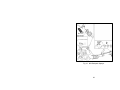
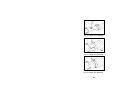
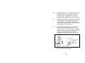
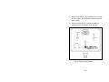
22. The air low-pressure cut-off switch is located inside
the coupling guard and is mounted on the rear of the
pressure gauge. If necessary, this switch can be
adjusted in the field by removing the rubber plug
from the tip of the switch and then using a 7/32”
Allen wrench, turn the adjustment screw in about ½
turn increments. Turning clockwise increases the air
pressure cut-off point. Turning counter-clockwise
decreases the air pressure cut-off point.
SETTING THE FLOW RATE
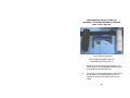
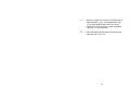
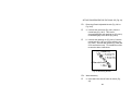
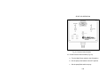
23. With the engine running, open the cover of the flow
control box.
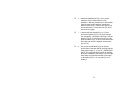
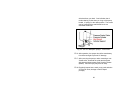
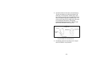
24. Loosen the pump pointer locking plate by loosening
the two round knurled knobs, one on each side of
the locking plate. Loosen only enough to move the
pointer. The pointer should be moved against a
slight pressure.
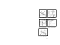
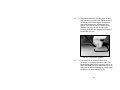
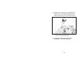
25. Turn the black knob on the side of the pump to
increase or decrease the flow setting. The flow
scale is an arbitrary scale and is marked from 0-10
(zero to ten), which represents 0-100% of flow rate.
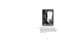
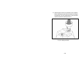
26. Set the flow rate by following the instructions in the
CALIBRATION section on page 19 of the instruction
manual. The correct flow rate, along with correct
nozzle pressure, is one of the main criteria for good
particle size. Always retighten the knurled knobs
before checking the flow rate, as a loose pointer will
162