1
Installation Instructions
PLC-5 Ethernet Interface Module
Catalog Number 1785-ENET,
Series C, Revision B
Topic
Page
About This Publication
1
Important User Information
2
About the Module
5
Before You Begin
15
Install the Module
16
Establish an Ethernet Connection
26
Monitor Ethernet Status Data
27
Use the Message Instruction
27
Interpret Error Codes
30
Domain Name Service
31
Embedded Web Server
32
Interpret the LED Indicators
43
Specifications
45
Additional Resources
47
About This Publication
This publication helps you:
• understand what equipment you need to install
the module.
• install and configure the module.
• connect to an Ethernet link and communicate
via the module.
Publication 1785-IN019B-EN-P - January 2007
2
PLC-5 Ethernet Interface Module
Important User Information
Solid state equipment has operational characteristics differing from those of electromechanical equipment.
Safety Guidelines for the Application, Installation and Maintenance of Solid State Controls (publication
SGI-1.1 available from your local Rockwell Automation sales office or online at
http://literature.rockwellautomation.com) describes some important differences between solid state
equipment and hard-wired electromechanical devices. Because of this difference, and also because of the
wide variety of uses for solid state equipment, all persons responsible for applying this equipment must
satisfy themselves that each intended application of this equipment is acceptable.
In no event will Rockwell Automation, Inc. be responsible or liable for indirect or consequential damages
resulting from the use or application of this equipment.
The examples and diagrams in this manual are included solely for illustrative purposes. Because of the many
variables and requirements associated with any particular installation, Rockwell Automation, Inc. cannot
assume responsibility or liability for actual use based on the examples and diagrams.
No patent liability is assumed by Rockwell Automation, Inc. with respect to use of information, circuits,
equipment, or software described in this manual.
Reproduction of the contents of this manual, in whole or in part, without written permission of Rockwell
Automation, Inc., is prohibited.
Throughout this manual, when necessary, we use notes to make you aware of safety considerations.
WARNING
IMPORTANT
ATTENTION
Identifies information about practices or circumstances that can cause an explosion in
a hazardous environment, which may lead to personal injury or death, property
damage, or economic loss.
Identifies information that is critical for successful application and understanding of
the product.
Identifies information about practices or circumstances that can lead to personal injury
or death, property damage, or economic loss. Attentions help you to identify a hazard,
avoid a hazard, and recognize the consequences.
SHOCK HAZARD
Labels may be located on or inside the equipment, for example, a drive or motor, to
alert people that dangerous voltage may be present.
BURN HAZARD
Labels may be located on or inside the equipment, for example, a drive or motor, to
alert people that surfaces may be dangerous temperatures.
Publication 1785-IN019B-EN-P - January 2007
PLC-5 Ethernet Interface Module
3
Environment and Enclosure
This equipment is intended for use in a Pollution Degree 2 industrial
environment, in overvoltage Category II applications (as defined in IEC
publication 60664-1), at altitudes up to 2000 m (6561 ft) without derating.
ATTENTION
This equipment is considered Group 1, Class A industrial equipment according
to IEC/CISPR Publication 11. Without appropriate precautions, there may be
potential difficulties ensuring electromagnetic compatibility in other
environments due to conducted as well as radiated disturbance.
This equipment is supplied as open-type equipment. It must be mounted within
an enclosure that is suitably designed for those specific environmental
conditions that will be present and appropriately designed to prevent personal
injury resulting from accessibility to live parts. The enclosure must have
suitable flame-retardant properties to prevent or minimize the spread of flame,
complying with a flame spread rating of 5VA, V2, V1, V0 (or equivalent) if
non-metallic. The interior of the enclosure must be accessible only by the use
of a tool. Subsequent sections of this publication may contain additional
information regarding specific enclosure type ratings that are required to
comply with certain product safety certifications.
Besides this publication, see:
• Industrial Automation Wiring and Grounding Guidelines, for additional
installation requirements, Allen-Bradley publication 1770-4.1.
• NEMA Standards publication 250 and IEC publication 60529, as
applicable, for explanations of the degrees of protection provided by
different types of enclosure.
Prevent Electrostatic Discharge
ATTENTION
This equipment is sensitive to electrostatic discharge that can cause internal
damage and affect normal operation. Follow these guidelines when you handle
this equipment:
•
•
•
•
•
•
Touch a grounded object to discharge potential static.
Wear an approved grounding wrist strap.
Do not touch connectors or pins on component boards.
Do not touch circuit components inside the equipment.
Use a static-safe workstation, if available.
Store the equipment in appropriate static-safe packaging when not
in use.
Publication 1785-IN019B-EN-P - January 2007
4
PLC-5 Ethernet Interface Module
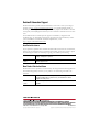
North American Hazardous Location Approval
The following information applies when
operating this equipment in hazardous locations
Informations sur l’utilisation de cet
équipement en environnements dangereux
Products marked CL I, DIV 2, GP A, B, C, D are suitable
for use in Class I Division 2 Groups A, B, C, D,
Hazardous Locations and nonhazardous locations
only. Each product is supplied with markings on the
rating nameplate indicating the hazardous location
temperature code. When combining products within a
system, the most adverse temperature code (lowest
“T” number) may be used to help determine the
overall temperature code of the system. Combinations
of equipment in your system are subject to
investigation by the local Authority Having
Jurisdiction at the time of installation.
Les produits marqués CL I, DIV 2, GP A, B, C, D ne
conviennent qu’à une utilisation en environnements
de Classe I Division 2 Groupes A, B, C, D dangereux
et non dangereux. Chaque produit est livré avec des
marquages sur sa plaque d’identification qui
indiquent le code de température pour les
environnements dangereux. Lorsque plusieurs
produits sont combinés dans un système, le code de
température le plus défavorable (code de
température le plus faible) peut être utilisé pour
déterminer le code de température global du
système. Les combinaisons d’équipements dans le
système sont sujettes à inspection par les autorités
locales qualifiées au moment de l’installation.
WARNING
EXPLOSION HAZARD • Do not disconnect equipment
unless power has been removed
or the area is known to be
nonhazardous.
• Do not disconnect connections to
this equipment unless power has
been removed or the area is
known to be nonhazardous.
Secure any external connections
that mate to this equipment by
using screws, sliding latches,
threaded connectors, or other
means provided with this product.
• Substitution of components may
impair suitability for Class I,
Division 2.
• If this product contains batteries,
they must only be changed in an
area known to be nonhazardous.
Publication 1785-IN019B-EN-P - January 2007
AVERTISSEMENT
RISQUE D’EXPLOSION –
• Couper le courant ou s’assurer
que l’environnement est classé
non dangereux avant de
débrancher l'équipement.
• Couper le courant ou s'assurer
que l’environnement est classé
non dangereux avant de
débrancher les connecteurs.
Fixer tous les connecteurs
externes reliés à cet
équipement à l'aide de vis,
loquets coulissants,
connecteurs filetés ou autres
moyens fournis avec ce produit.
• La substitution de composants
peut rendre cet équipement
inadapté à une utilisation en
environnement de Classe 1,
Division 2.
• S’assurer que l’environnement
est classé non dangereux avant
de changer les piles.
PLC-5 Ethernet Interface Module
5
European Hazardous Location Approval
European Zone 2 Certification (The following applies when the product bears the EEx
marking.)
This equipment is intended for use in potentially explosive atmospheres as defined by European
Union Directive 94/9/EC.
The LCIE (Laboratoire Central des Industries Electriques) certifies that this equipment has been found to
comply with the Essential Health and Safety Requirements relating to the design and construction of
Category 3 equipment intended for use in potentially explosive atmospheres, given in Annex II to this
Directive.
Compliance with the Essential Health and Safety Requirements has been assured by compliance with EN
60079-15.
IMPORTANT
This equipment is not resistant to sunlight or other sources of UV radiation.
Equipment must be installed in an enclosure providing at least IP54 protection
when applied in Class I, Zone 2 environments.
This equipment shall be used within its specified ratings defined by
Allen-Bradley.
This equipment must be used only with ATEX certified backplanes.
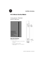
About the Module
The PLC-5 Ethernet interface module is an EtherNet/IP-compliant, single-slot module that
attaches to the side of any PLC-5 controller, series B or later, to provide Ethernet connectivity
to the controller.
Module Functionality
When used with
The module provides
Enhanced PLC-5 controller
Ethernet connectivity without sacrificing DH+/RIO ports.
ControlNet PLC-5 controller
Ethernet connectivity.
Ethernet PLC-5 controller
ability to operate dual Ethernet links.
Use the module with a programming software package that supports configuration for
channel 3A and the following controllers.
Publication 1785-IN019B-EN-P - January 2007
6
PLC-5 Ethernet Interface Module
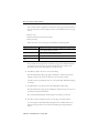
PLC-5 Series/Revision Compatibility
Series
Revision
Controller
E and later
Any
All Enhanced, Ethernet, and ControlNet PLC-5 controllers
D
B
PLC-5/11, PLC-5/20, PLC-5/26, PLC-5/30, PLC-5/40, PLC-5/40L, PLC-5/46,
PLC-5/60, PLC-5/60L, PLC-5/80, PLC-5/86
PLC-5/20E, PLC-5/40E, PLC-5/80E
PLC-5/20C, PLC-5/40C, PLC-5/80C
C
K
PLC-5/11, PLC-5/20, PLC-5/26, PLC-5/30, PLC-5/40, PLC-5/40L, PLC-5/46,
PLC-5/60, PLC-5/60L, PLC-5/80, PLC-5/86
PLC-5/20E, PLC-5/40E, PLC-5/80E
PLC-5/20C, PLC-5/40C, PLC-5/80C
B
L
PLC-5/40, PLC-5/40L, PLC-5/46, PLC-5/60, PLC-5/60L
A
L
PLC-5/30
A
K
PLC-5/11, PLC-5/20, PLC-5/26
All ControlNet 1.5 PLC-5 controllers support the module.
Channel 3A Default
The module’s channel 3A default is Autonegotiate 10/100 Mbps half duplex.
Enhancement to Series C, Revision B
The module is capable of managing a sustained Ethernet traffic rate of 45 frames per 10 ms
interval. In the rare cases when traffic exceeds that, the module will activate a storm handling
mechanism. When this occurs, the module may drop some received frames to prevent it from
locking up. The module increments the storm counter once during this interval. Transmission
Control Protocol (TCP) frames that were dropped during the storm will be retransmitted by
the source. To minimize the chances of storms occurring, use Ethernet switches instead of
Ethernet hubs.
Enhancements to Series C, Revision A
The series C, revision A version of the module’s firmware included these enhancements:
•
•
•
•
•
•
•
BOOTP, DHCP, or Static entry of IP address
Auto-negotiate speed selection
Full/Half-duplex port setting
10/100 Mbps speed selection
Email client functionality
Enable/Disable HTTP Web server
Enable/Disable SNMP functionality
Publication 1785-IN019B-EN-P - January 2007
PLC-5 Ethernet Interface Module
7
Follow these directions to see or activate the new configuration and status features:
1. Open or create a project in RSLogix 5 software, version 7.1 or later.
2. Click the Channel Configuration menu.
You see the Edit Channel Properties screen.
3. Click the Channel 3A tab.
4. Select Ethernet/C from the Channel Type pull-down menu.
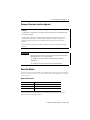
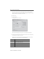
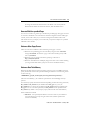
BOOTP, DHCP, or Static Entry of IP Address
As shown in the following dialog, you can select between a static or dynamic network
configuration.
• The default is Dynamic Network Configuration Type and
Use BOOTP to obtain network configuration.
• If you choose a dynamic network configuration, you can change the default BOOTP
to DHCP.
• If you choose a static network configuration type, you must enter the IP address.
Similarly, if you have a dynamic network configuration, DHCP or BOOTP assigns the
controller’s hostname. With a static configuration, you assign the hostname.
Publication 1785-IN019B-EN-P - January 2007
8
PLC-5 Ethernet Interface Module
When you create a hostname, consider these naming conventions.
• The hostname can be a text string up to 24 characters.
• The hostname can contain alphanumeric (A through Z, 0...9) and may contain a
period and minus sign.
• The first character must be an alpha character.
• The last character must not be a minus sign.
• You cannot use blank spaces or space characters.
• The hostname is not case-sensitive.
Auto Negotiate Speed and Duplex Selection
In the Edit Channel 3A properties dialog, you can either leave the Auto Negotiate checkbox
checked, which lets the controller negotiate a speed and duplex port setting, or you can
uncheck the Auto Negotiate checkbox, which forces the port setting to a particular speed and
duplex port setting.
If you uncheck the Auto Negotiate checkbox, the port setting lets you select the range of
speed and duplex settings that the controller negotiates. The default port setting with Auto
Negotiate checked is 10/100 Mbps half duplex, which lets the controller negotiate any of its
four available settings.
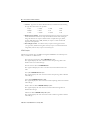
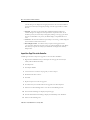
The following table lists the order the controller negotiates for each setting.
Set Negotiation Order
Setting
10/100 Mbps Full
Duplex/Half Duplex
100 Mbps Full Duplex or
100 Mbps Half Duplex
100 Mbps Full Duplex or
10 Mbps Full Duplex
100 Mbps Half Duplex or
10 Mbps Full Duplex
100 Mbps Full Duplex
100 Mbps Half Duplex
10 Mbps Full Duplex
10 Mbps Half Duplex Only
100 Mbps
Full Duplex
1st
100 Mbps
Half Duplex
2nd
1st
2nd
1st
1st
10 Mbps
Full Duplex
3rd
3rd
2nd
3rd
2nd
3rd
1st
1st
Publication 1785-IN019B-EN-P - January 2007
10 Mbps
Half Duplex
4th
1st
2nd
2nd
2nd
1st
PLC-5 Ethernet Interface Module
9
Unchecked Autonegotiate Checkbox and Corresponding Port Settings
Checked Autonegotiate Checkbox and Corresponding Port Settings
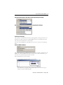
Email Client Functionality
The controller is an email client that sends an email triggered by a message instruction via a
mail relay server. The controller uses standard SMTP protocol to forward the email to the
relay server. The controller does not receive email.
You must enter the SMTP Server’s IP address into the text box as shown in the following
dialog.
Enter the SMTP IP Address
The controller supports login authentication. If you want the controller to authenticate to the
SMTP server, check the SMTP authentication checkbox. If you select authentication, you
must also use a username and password for each email.
Follow these directions to create an email:
1. Create a message instruction similar to the one below.
The destination (to), the reply (from), and the body (text) are stored as strings in
elements of separate ASCII string files.
Publication 1785-IN019B-EN-P - January 2007
10
PLC-5 Ethernet Interface Module
If you want to send an email to a specific recipient when a controller application
generates an alarm or reaches a certain condition, program the controller to send the
message instruction to the destination of the email.
2. Verify the rung.
3. Click Setup Screen.
A dialog appears like the one below.
The three Data fields display the string values of the ST file element addresses.
4. Enter the appropriate information into the Data fields and Username and Password,
if Authentication is enabled, to send email.
Examine the Error Code (denoted in Hex) and Error Description areas within the
General tab to see if the message was successfully delivered.
Error Code (hex)
Description
0x000
Delivery successful to the mail relay server.
0x002
Resource unavailable. The email object was unable to obtain memory
resources to initiate the SMTP session.
0x101
SMTP mail server IP address not configured.
0x102
To (destination) address not configured or invalid.
0x103
From (reply) address not configured or invalid.
0x104
Unable to connect to SMTP mail server.
Publication 1785-IN019B-EN-P - January 2007
PLC-5 Ethernet Interface Module
Error Code (hex)
Description
0x105
Communication error with SMTP server.
0x106
Authentication required.
0x017
Authentication failed.
11
Channel 3A Status
Follow these directions to check the status of channel 3A:
1. Click Channel Status in your RSLogix 5 software project.
You see the Channel Status menu.
2. Click the Channel 3A tab.
3. Click the Port tab.
You see the status for each port configuration.
Publication 1785-IN019B-EN-P - January 2007
12
PLC-5 Ethernet Interface Module
Enable/Disable HTTP Web Server
You can disable the HTTP Web server functionality from within the Channel 3A
Configuration by unchecking the HTTP Server Enable checkbox shown below.
The default (checked box) lets you connect to the controller using a Web browser. Although
this parameter can be downloaded to the controller as part of a program download or
changed and applied while online with the controller, you must cycle power to the controller
for the change to take affect.
Enable/Disable Simple Network Management Protocol (SNMP)
You can disable the controller’s SNMP functionality from within the Channel 3A
Configuration by unchecking the SNMP Server Enable checkbox.
The default (checked box) lets you connect to the controller using an SNMP client. Although
this parameter can be downloaded to the controller as part of a program download or
changed and applied while online with the controller, you must cycle power to the controller
for the change to take affect.
Series B, Revision D, or Later, Module Features
This release introduced the following features.
Domain Name Service (DNS)
DNS is an enhancement that translates a user-defined name into an Internet Protocol (IP)
address.
Publication 1785-IN019B-EN-P - January 2007
PLC-5 Ethernet Interface Module
13
Web Diagnostics and Module Information
This enhancement is a user-friendly tabularized view of Web diagnostics and module
information.
Web User-provided Pages (WUPP)
WUPP lets you create your own custom Web pages to provide executive summaries of
process information. The Web pages can contain data table elements, text, and images. These
pages are accessible to any Internet user who has network access to the PLC-5 controller.
Web Custom-data Monitor (WCDM)
WCDM is a specialized WUPP that creates a Web page to view these elements in table form.
Internet Scanner Test
Using the Internet Scanner, version 6.21.2001.320, the module passes network-vulnerability
tests with the exception of Simple Network Management Protocol (SNMP). While the PLC-5
controller has default SNMP passwords, the controller SNMP information is read-only. If you
prefer to limit access to SNMP information, we recommend you configure your network to
filter out SNMP requests. For more information, contact Rockwell Automation Technical
Support at 440.646.3223.
TCP/IP
The module’s TCP/IP communications have been updated for enhanced UDP message
support and super-netting
SLC 5/05 Messaging
The module supports SLC Typed Read and Write MSG instructions through the Ethernet
interface module to SLC 5/05 controllers
Additional Ethernet-channel Diagnostics
The module includes additional Ethernet-channel diagnostics when using the module with
any of the following series/revisions of PLC-5 controllers:
•
•
•
•
Series E, Revision E or later
Series D, Revision F.1 or later
Series C, Revision P.1 or later
Series B, Revision P.1 or later
Publication 1785-IN019B-EN-P - January 2007
14
PLC-5 Ethernet Interface Module
The additional diagnostics are available for use within a user program as words 44...49 of the
Ethernet diagnostic file:
Word
44
45...47
48...49
Displays
Not used
Ethernet hardware address
Assigned Internet protocol (IP) ddress
Words 45...47 contain the six-digit Ethernet hardware address. For example, if the Ethernet
hardware address is 00:00:BC:03:00:1D, words 45...47 would contain
000 BC03 001D.
Words 48 and 49 contain 4 bytes of data, with each byte holding one of the numbers of the
address, in hex, in the dot-address format. For example, an IP address of 142.169.124.1 will
be displayed as 8EA9 7C01.
To access these additional words, you must create the diagnostic file in the channel
configuration and manually expand the data table file from 44 to 50 words.
Multihop Messaging Over the Ethernet Network
This lets you communicate over the Ethernet network with ControlLogix devices or through
a ControlLogix Ethernet module (1756-ENET) to other PLC-5 and SLC controllers. You
need a series E, revision D or later, PLC-5 controller with a series B, or later, 1785-ENET
interface module. Keep in mind these considerations:
• RSLogix programming software on ControlNet and DH+ links cannot see the
controllers on an Ethernet link.
• The RSLinx DDE server on a ControlNet link cannot poll data from the controllers
on an Ethernet link.
• The RSLinx DDE server on a ControlNet link cannot accept unsolicited data from
controllers on an Ethernet link.
• Applications that register themselves as nodes on the RSLinx Virtual Link in
workstations on the ControlNet network cannot accept unsolicited packets from
controllers on the Ethernet network.
• Applications that register themselves as nodes on the RSLinx Virtual Link in
workstations on an Ethernet link cannot accept unsolicited packets from the
controllers on an Ethernet link.
When an outbound connection's inactivity timer has expired and a MSG is pending on that
connection, the MSG receives an error. On a multihop connection, the error is 0x18 (Broken
Connection). On a non-multihop connection, the error is 0x16 (Connection Timeout).
For non-multihop connections, the Connection Inactivity Timeout is user configurable. For
multihop connections, it is not configurable. Instead, it uses a default timeout value of 17
seconds.
Publication 1785-IN019B-EN-P - January 2007
PLC-5 Ethernet Interface Module
15
Before You Begin
Follow these directions before installing your module:
1. Check your Ethernet interface module package.
2. Make certain that you have the following items:
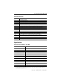
Quantity Description
1
1785-ENET Ethernet Interface Module
1
Connector kit containing 1 PLC-5 controller 58-pin connector header
1
Industrial Automation Wiring and Grounding Guidelines, publication 1770-4.1
1
PLC-5 Ethernet Interface Module Installation Instructions, publication 1785-IN019
If any items are missing or incorrect, contact your local distributor or Rockwell Automation
representative.
3. Locate and record the Ethernet hardware address.
Your module is assigned an Ethernet hardware address at the factory. Look for this
address in the back, lower corner of your module, or in the channel 3A configuration
dialog in RSLogix 5 programming software.
Ethernet
EthernetHardware
hardware
Address
addressLabel
label
Publication 1785-IN019B-EN-P - January 2007
16
PLC-5 Ethernet Interface Module
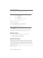
Parts List
Required Tools
The 1785-ENET is a modular component of the 1771 I/O system requiring a properly
installed system chassis. Refer to Universal Chassis I/O Installation Instructions, publication
1771-IN075, for detailed information on an acceptable chassis along with proper installation
and grounding requirements. Limit the maximum adjacent slot power dissipation to 10 W.
Install the Module
WARNING
If you connect or disconnect the communications cable with power applied to
this module or any device on the network, an electrical arc can occur. This could
cause an explosion in hazardous location installations.
Follow these directions to install the module:
1. Attach the connector header to the controller.
2. Connect the module to the controller.
Publication 1785-IN019B-EN-P - January 2007
PLC-5 Ethernet Interface Module
17
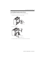
3. Install the combination into the chassis.
IMPORTANT
If your power supply is already installed in the chassis, be sure the power
supply is OFF before you install the module. If you install the module with
power ON, you will damage the module.
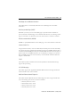
Attach the Connector Header to the Controller
With grounding wrist strap attached to your wrist, follow these steps:
1. Locate the controller’s connector header port.
2. Push the exposed pins into the holes on the controller.
3. Attach the module to the end of the connector header.
IMPORTANT
Make certain you carefully align the pins and holes together before you press
the connector header into the controller. Improper alignment will bend the
connector header pins.
Publication 1785-IN019B-EN-P - January 2007
18
PLC-5 Ethernet Interface Module
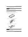
Connect the Module to the Controller
1. Align the pins and holes on the module to those on the connector header.
2. Press the module into the connector header.
3. Tighten the screws.
IMPORTANT
Make certain you carefully align the pins and holes together before you press
the connector header into the controller. Improper alignment will bend the
connector header pins.
Publication 1785-IN019B-EN-P - January 2007
PLC-5 Ethernet Interface Module
19
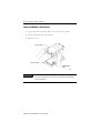
Install the Module Combination into the Chassis
With grounding wrist strap attached to your wrist, follow these steps:
1. Make certain the power to the chassis is OFF.
20615
2. Raise the locking bar.
20616
3. Insert the module combination into the leftmost slots of the chassis.
Publication 1785-IN019B-EN-P - January 2007
20
PLC-5 Ethernet Interface Module
4. Lower the locking bar into place.
20617
Configure the Module for Ethernet Communication
Before configuring channel 3A for Ethernet communication, be sure to:
• know the Ethernet hardware address.
• assign an IP address to the module.
Because the module uses the TCP/IP protocol, each Ethernet hardware address on the
network requires a unique IP address.
If the module is connected to
You must assign
an Ethernet PLC-5 controller
two IP addresses:
• one for the controller.
• one for the module.
an Enhanced PLC-5 controller
one (1) IP address for the module.
a ControlNet PLC-5 controller
one (1) IP address for the module.
The IP address is software-configurable using either the BOOTP protocol or your
programming software package.
Contact your network administrator for a unique IP address to assign to your module.
Configure Channel 3A
Once you obtain the IP address that you will assign to the module, you must configure
channel 3A so your network recognizes the module.
Publication 1785-IN019B-EN-P - January 2007
PLC-5 Ethernet Interface Module
21
Use your programming software package to designate channel 3A as the channel that
supports the module if you are configuring offline (if you are configuring online, designation
is automatic).
IMPORTANT
To configure the module online, it must be attached to the controller.
Specify Ethernet Information
Specify Ethernet information for the interface module by doing one of the following:
• Manually enter module configuration information using the screens within your
programming software package.
• Supply module configuration information using a BOOTP utility (use a BOOTP
server on your network and edit the BOOTPTAB file).
Manually Enter Module Configuration Information
The default for the Ethernet interface module is BOOTP enabled. You must first disable
BOOTP before you can use the programming software to enter module configuration
information.
To disable BOOTP and to manually enter module configuration information for channel 3A,
follow the steps specified in your programming software documentation.
Publication 1785-IN019B-EN-P - January 2007
22
PLC-5 Ethernet Interface Module
Enter configuration information in the appropriate fields.
This Field
Specifies
Diagnostics file The file containing the
channel’s status
information
Configure by Doing the Following
Cursor to the field, type an unused integer file number (10...999), and press
Enter. The system creates an integer file 44 words long.
Important: Do not assign a diagnostic file number that is the I/O status file you
assigned to another communication channel or any other used file.
Unpredictable machine action can result.
Important: You must define a diagnostics file for a channel configured for
anything but unused (even if you are not using the channel) if you want status
information for that channel.
Ethernet
address
The interface module’s
Ethernet hardware
address
Assigned at factory and cannot be changed.
Displayed as a set of 6 bytes (in hex), separated by colons.
Display only
IP address
The interface module’s
Internet address
Cursor to the field, and enter an address in this form:
a.b.c.d Where: a, b, c, d are between 1...254 (decimal)
You must specify the IP address to have the interface module connect to the
TCP/IP network. Do not use 0 or 255 as a, b, c, or d in the IP address.
BOOTP enable
Whether BOOTP is
enabled
Cursor to the field and specify No (for manual configuration).
Before you disable BOOTP, make sure you have an IP address specified. With
BOOTP set to No, the interface module uses the parameters that you specify
locally.
MSG conn
timeout
The number of ms allowed Cursor to the field, and enter a timeout period in ms. (The interface module
for an MSG instruction to rounds to the nearest 250 ms.) The valid range for a timeout period is 0...65,535
establish a connection
ms.
with the destination node
The default is 15,000 ms.
MSG reply
timeout
The number of ms the
Ethernet interface waits
for a reply to a command it
initiated (through an MSG
instruction)
Cursor to the field, and enter a timeout period in ms. (The interface module
rounds to the nearest 250 ms.) The valid range for a timeout period is 0...65,535
ms.
The default is 3,000 ms.
Publication 1785-IN019B-EN-P - January 2007
PLC-5 Ethernet Interface Module
23
This Field
Specifies
Configure by Doing the Following
Inactivity
timeout
The number of minutes of
inactivity before the
connection is closed
Cursor to the field, and enter a timeout period in minutes. The valid range for a
timeout period is 0...65,535 minutes.
The default is 30 minutes.
Broadcast
address
The broadcast address to
which the controller
should respond
Subnet mask
The controller’s subnet
mask (used when network
has subnets)
Gateway
address
The IP address of the
gateway that provides a
connection to another IP
network
Link ID
A DH+ link number
See the Enhanced and Ethernet PLC-5 Programmable Controllers User Manual,
publication 1785-UM012, for information about how to configure these
advanced Ethernet functions.
Enter a link ID number. The valid range is 0...199.
Use the link ID number to Only enter a Link ID number if you plan to configure multihop MSG instructions
identify the controller
through a 1756-DHRIO module in a ControlLogix chassis.
when configuring a
ControlLogix system using
the ControlLogix Gateway
software
After entering the channel 3A configuration information, either accept edits or access status
information about channel 3A.
Use BOOTP to Enter Configuration Information
BOOTP is a protocol that supplies the interface module with configuration information
when you apply power. BOOTP lets you dynamically assign IP addresses to devices on the
Ethernet link.
To use BOOTP, a BOOTP server must exist on the local Ethernet subnet. The server is a
computer (either a personal computer, VAX, or UNIX system) that has BOOTP-server
software installed and reads a text file containing network information for individual nodes
on the network.
To enable BOOTP, follow the steps specified in your programming software documentation
to specify Ethernet configuration information.
When BOOTP is enabled, the following events occur when you cycle power:
• The controller broadcasts a BOOTP-request message containing its hardware address
over the local network or subnet.
• The BOOTP server compares the hardware address with the addresses in its look-up
table in the BOOTPTAB file.
• The BOOTP server sends a message back to the controller with the IP address and
other network information that corresponds to the hardware address it received.
Publication 1785-IN019B-EN-P - January 2007
24
PLC-5 Ethernet Interface Module
With all hardware and IP addresses in one location, you can easily change IP addresses in the
BOOTP configuration file if your network needs change.
Edit the BOOTPTAB Configuration File
IMPORTANT
Be certain you know your Ethernet hardware address as you will enter it in this
file.
You must edit the BOOTPTAB file, which is an ASCII text file, to include the name, IP
address, and hardware address for each Ethernet interface module you want the server to
boot. Follow these directions to edit this file:
1. Open the BOOTPTAB file using a text editor.
The file contains lines that look like this:
#Default string for each type of Ethernet client
defaults5E: ht=1:vm=rfc1048
These are the default parameters for Ethernet PLC-5 interface module and must
always precede the client lines in the BOOTPTAB file.
The file also contains a line that looks like this:
sidecar: tc=default5E:ip=aa.bb.cc.dd:ha=0000BC03xxyy
IMPORTANT
Use this line as the configuration template for Ethernet devices.
2. Make one copy of the Ethernet device template for every PLC-5 Ethernet interface
module in your system (one line per module).
3. Edit each copy of the template:
a. Replace sidecar with the name you assigned the Ethernet interface module.
Use only letters and numbers; do not use underscores.
b. Replace aa.bb.cc.dd with the IP address to be assigned to the interface
module.
c. Replace xxyy with the last four digits of the Ethernet hardware address.
Use only valid hexadecimal digits (0...9, A through F); do not use the hyphens or
colons that separate the numbers. (You will find the hardware address on a label
affixed to the printed circuit board of the module.)
4. Save, close, and make a backup copy of this file.
Publication 1785-IN019B-EN-P - January 2007
PLC-5 Ethernet Interface Module
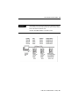
EXAMPLE
25
The following system shows three controllers (two enhanced controllers
and one Ethernet controller) with attached 1785–ENET interface modules
and a workstation with a BOOTP server.
The names and hardware addresses are device specific.
Publication 1785-IN019B-EN-P - January 2007
26
PLC-5 Ethernet Interface Module
Based on this configuration, the BOOTPTAB file would look like this:
#
#
Legend:
gw -- gateways
ha -- hardware address
#
#
#
ht -- hardware type(1)
ip -- host IP address
sm -- subnet mask
#
#
vm -- BOOTP vendor extensions format(2)
tc -- template host
#Default string for each type of Ethernet client
defaults5E: ht=1:vm=rfc1048
#Entries
device1:
device2:
device4:
for 1785-ENET modules:
tc=defaults5E:ip=12.34.56.1:ha=0000BC031234
tc=defaults5E:ip=12.34.56.2:ha=0000BC035678
tc=defaults5E:ip=12.34.56.4:ha=0000BC038827
#Entries for Ethernet PLC-5 controllers:
device3: tc=defaults5E:ip=12.34.56.3:ha=0000BC1C9012
(1)
(2)
1 = 10MB Ethernet
use rfc1048
Run your BOOTP server utility and then cycle power on the chassis that contains the
Ethernet interface module. This sends the configuration information to the module.
Apply Power to the Chassis
When you cycle power, the interface module performs the following functions:
• establishes communication with the controller.
• broadcasts BOOTP requests if BOOTP is enabled.
Establish an Ethernet Connection
The module supports 64 simultaneous connections per module. A connection is a unique
path to an end device, such as a ControlNet controller on a ControlNet link attached via a
1756-CNB module. Each unique path uses a different connection. There is an exception for a
controller on a DH+ link attached via a 1756-DHRIO module. Each 1756-DHRIO module
uses only one connection, regardless of how many devices are attached to it and how many
paths you define to those devices.
Multiple MSG instructions can use the same path to a device, but only one connection is used
because the path is the same.
Publication 1785-IN019B-EN-P - January 2007
PLC-5 Ethernet Interface Module
27
Monitor Ethernet Status Data
Monitor communication status through the module by accessing the Ethernet Channel 3A
status dialog.
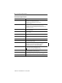
Ethernet Status Data
Status Field
Commands
Replies
Ethernet
Bytes
Displays the Number of
Sent
0...3
Commands sent by the channel
Received
4...7
Commands received by the channel
Sent
8...11
Replies sent by the channel
Received
12...15
Replies received by the channel
Sent with error
16...19
Replies containing errors sent by the channel
Received with error
20...23
Replies containing errors received by the channel
Timed out
24...27
Replies not received within the specified timeout period
In octets
28...31
Octets received on the channel
Out octets
32...35
Octets sent on the channel
In packets
36...39
Packets received on the channel, including broadcast packets
Out packets
40...43
Packets sent on the channel, including broadcast packets
Alignment errors
44...47
Frames received on the channel that are not an integral number of
octets in length
FCS errors
48...51
Frames received on the channel that do not pass the FCS check
Carrier sense errors
52...55
Times that the carrier sense condition was lost or never asserted
while trying to transmit a frame
Excessive collisions
56...59
Frames for which a transmission fails due to excessive collisions
Excessive deferrals
60...63
Frames for which a transmission is deferred for an excessive period
of time
MAC receive errors
64...67
Frames for which reception on an interface fails due to internal
MAC sublayer receive error
MAC transmit errors
68...71
Frames for which reception on an interface fails due to internal
MAC sublayer transmission error
Single collisions
72...75
Successfully transmitted frames for which transmission was
delayed because of collision
Multiple collisions
76...79
Successfully transmitted frames for which transmission was
delayed more than once because of collision
Deferred
transmissions
80...83
Frames for which the first transmission attempt is delayed because
the medium is busy
Late collisions
84...87
Times that a collision is detected later than 512 bit-times into the
transmission of a packet
Use the Message Instruction
The message (MSG) instruction transfers up to 1000 elements of data; the size of each
element depends on the data table section that you specify and the type of message command
that you use. One binary element contains one 16-bit word, for example, and one
floating-point element contains two 16-bit words.
Publication 1785-IN019B-EN-P - January 2007
28
PLC-5 Ethernet Interface Module
The MSG instruction transfers data in packets. Each packet can contain up to 709 words for
Ethernet controllers and interface modules. If your message transfer contains more words
than fit in one packet, the transfer requires more than one packet of transfer data. The more
packets of data to transfer, the longer the total transfer takes.
Enter Parameters
The control block is where all of the information relating to the message is stored. Ethernet
message instructions use two consecutive control blocks:
This Block
Contains
First
Message information
Second
Destination address
IMPORTANT
Because Ethernet messages need two consecutive control blocks, the
message control block that you specify must start on an even element
number.
Use your programming software package to enter the control block address. After entering
the control block, the programming terminal automatically displays a data entry dialog, from
which you enter instruction parameters that are stored at the control block address.
Parameter Descriptions
This Parameter
Specifies
Command Type
Whether the MSG instruction performs a read or write operation. The software toggles
between: PLC-5 Typed Read, PLC-5 Typed Write, PLC-5 Typed Write to SLC, PLC-5 Typed
Read from SLC, SLC Typed Logical Read, SLC Typed Logical Write, PLC-2 Unprotected
Read, PLC-2 Unprotected Write, PLC-3 Word Range Read, and PLC-3 Word Range Write.
PLC-5 Data Table
Address
The data file address of the controller containing the message instruction. If the MSG
operation is write, this address is the starting word of the source file. If the MSG
operation is read, this address is the starting word of the destination file.
Size in Elements
The number of elements (1...1000) to be transferred.
Destination Address The starting address of the source or destination file in the target controller.
Port Number
The channel for message communications. Communications through the Ethernet
interface module use channel 3A.
When you enter 3A as the port number, an Ethernet instruction entry dialog appears. In
addition to the information you entered previously, this dialog includes a field for entering the
Host/Internet (IP) address. Enter the IP address of the destination controller here.
Publication 1785-IN019B-EN-P - January 2007
PLC-5 Ethernet Interface Module
29
The IP address specifies the MSG instruction’s destination node. If the destination is:
• a PLC-5/20E, PLC-5/40E, PLC-5/80E, or another 1785-ENET-equipped PLC-5
controller, the destination must be a full IP address.
• an INTERCHANGE client program, type CLIENT in the Destination Node field.
IMPORTANT
You must set the port number to 3A to access this function.
Use ControlLogix Devices for Communication
The Ethernet interface module, series A, revision E or later, with a PLC-5 controller can
communicate over the Ethernet network with ControlLogix devices or through a
ControlLogix Ethernet (1756-ENET) module to other PLC-5 controllers.
To communicate through a 1756-ENET module, you configure the multihop feature of a
MSG instruction from the Ethernet PLC-5 controller (or controller with 1785-ENET
module) to the target device. To do this, you need RSLogix 5 programing software.
For more information, see the MSG instruction in the PLC-5 Programmable Controller
Instruction Set Reference Manual, publication 1785-6.1.
If you want to go through the ControlLogix 1756-ENET module and out the 1756-DHRIO
module to the target device:
• Use RSNetWorx software to configure the 1756-DHRIO module routing table in the
ControlLogix system.
• Specify a Link ID number on channel properties for channel 2/3A of the Ethernet
PLC-5 controller (or PLC-5 controller with a 1785-ENET module).
For information on specifying the path of the MSG instruction, see the documentation for
your programming software.
Publication 1785-IN019B-EN-P - January 2007
30
PLC-5 Ethernet Interface Module
Interpret Error Codes
When the controller/interface module detects an error during the transfer of message data,
the controller sets the .ER bit and enters an error code that you can monitor from your
programming software.
Error Codes
Code
(Hexadecimal - word 1 of
the control block)
Description
(displayed on the data monitor screen)
0010
No IP address configured for the network
0011
Already at maximum number of connections
0012
Invalid internet address or host name
0013
No such host
0014
Cannot communicate with the name server
0015
Connection not completed before user-specified timeout
0016
Connection timed out by the network
0017
Connection refused by destination host
0018
Connection was broken
0019
Reply not received before user-specified timeout
001A
No network buffer space available
0037
Message timed out in local controller
0083
Controller is disconnected
0089
Controller’s message buffer is full
0092
No response (regardless of station type)
00D3
Control block formatted incorrectly
00D5
Incorrect address for the local data table
0500
Message timed out waiting for a response from a client
1000
Illegal command specified in MSG instruction.
2000
Error communicating with a client
3000
Client session has disconnected
4000
Controller connected but faulted (hardware)
5000
Client generated an error converting data.
6000
Requested function is not available. Client’s unsolicited handler
returned an error.
7000
Controller is in Program mode
8000
Controller’s compatibility file does not exist
9000
Client’s backlog has been exceeded
B000
Controller is downloading so it is inaccessible
F001
Controller incorrectly converted the address
Publication 1785-IN019B-EN-P - January 2007
PLC-5 Ethernet Interface Module
Code
(Hexadecimal - word 1 of
the control block)
Description
(displayed on the data monitor screen)
F002
Incomplete address
F003
Incorrect address
F006
Addressed file does not exist in target controller
F007
Destination file is too small for number of words requested
F00A
Target controller cannot put requested information in packets
F00B
Privilege error, access denied
F00C
Requested function is not available
F00D
Request is redundant
F011
Data type requested does not match data available
F012
Incorrect command parameters
31
Identify the Module Within a Network
The PLC-5 Ethernet Interface Module supports the Simple Network Management Protocol
(SNMP).
The module responds automatically to SNMP requests and maintains a management
information base (MIB) file (Level II). Information kept in this file could include:
• number of datagrams received.
• number of fragmented packets received.
• maximum number of TCP connections allowed.
Save and Restore Programs
You can physically and logically save and restore all programs, if you are using:
•
•
•
•
any release of RSLogix 5 programming software.
AI Programming Software, release 7.21 or later, for all logical saves/restores.
6200 Series Programming Software, release 5.2 or later, for all logical saves/restores.
an enhanced PLC-5 controller, series B or later.
Domain Name Service
DNS allows an Internet Protocol (IP) address in symbolic form to be converted into the
equivalent numeric IP address. For the PLC-5 controller, this conversion is a service provided
by a remote host on the network.
Publication 1785-IN019B-EN-P - January 2007
32
PLC-5 Ethernet Interface Module
With the latest release of the Ethernet PLC-5 controllers and RSLogix programming
software, version 5.20 or later, you can enter the symbolic form of the IP address as the IP
address in the Message Block.
The Channel Configuration feature in RSLogix5 programming software lets you configure a
primary and secondary DNS server, as well as a default domain name (for example,
cle.ab.com).
DNS names consist of a label name and a domain name. When programming the message
instruction, you can enter the full label and domain name (for example, Motor1.cle.ab.com) or
just the label name (Motor1). The default domain name (cle.ab.com) is appended to the label
name.
Label names must start with a letter and can only consist of letters, digits, and hyphens.
When a message instruction with a label name is first used, the PLC-5 controller verifies that
label name with the name servers. When the IP address is returned, the connection is made.
After the connection is made, subsequent message instructions will not require label name
verification.
Embedded Web Server
Follow these directions to use the embedded Web server:
1. Go online at your controller’s IP address (for example, www.cle.ab.com).
The 1785-ENET Ethernet Module main page appears.
2. Select the first item, Module Information.
The Module Information page appears and displays specific controller information.
3. Select TCP/IP Configuration at the bottom of the Module Information dialog.
The TCP/IP Configuration page appears and displays TCP/IP parameters.
4. Select Diagnostic Information at the bottom of the TCP/IP configuration dialog.
The Diagnostic Information page appears and displays two lists of statistics pages.
The first list contains Network Stack Statistics. These pages present information
about the TCP/IP stack.
For example, from the Network Stack Statistics list, select the first entry, General
Ethernet Counters.
Publication 1785-IN019B-EN-P - January 2007
PLC-5 Ethernet Interface Module
33
This page displays general messaging statistics. Use the information on this page
when troubleshooting the network.
Details of each counter on the General Ethernet Counters page are described in the
following table:
This Counter
Commands Sent
Replies Sent
Command Received
Replies Received
Replies Sent with Error
Replies Received with
Error
Replies Timed Out
In Octets
Out Octets
In Packets
Out Packets
Alignment Errors
FCS Errors
Carrier Sense Errors
Excessive Collisions
Excessive Deferrals
MAC Receive Errors
MAC Transmit Errors
Single Collisions
Multiple Collisions
Deferred Transmissions
Late Collisions
Packet Storms
Totals
Number of PCCC (programmable controller communication commands) sent by the
module
Number of PCCC replies sent by the module
Number of PCCC commands received by the module
Number of PCCC replies received by the module
Number of PCCC replies with error status send by the module
Number of PCCC replies with error status received by the module
Number of PCCC replies that were not received within the time period specified
on the Ethernet Configuration page
Number of octets received by the module
Number of octets sent by the module
Number of packets received by the module, including broadcast packets
Number of packets send by the module, including broadcast packets
Count of frames received that are not an integral number of octets in length
Count of frames that do not pass the FCS check
Number of times that the carrier sense condition was lost or never asserted when
attempting to transmit a frame
Count of frames when transmission fails caused by excessive collisions
Count of frames when transmission is deferred for an excessive period of time
Count of frames when transmission fails because of an internal MAC sublayer
receive error
Count of frames when transmission fails because of internal MAC sublayer
transmit error
Count of successfully transmitted frames when transmission is inhibited by one
collision
Ccount of successfully transmitted frames when transmission is inhibited by more
than one collision
Count of frames when the first transmission attempt is delayed because the
medium is busy
Number of times that a collision is detected later than 512 bit-times into the
transmission of a packet
Number of times the SONIC driver has entered storm or throttle back operation
due to excessive traffic
5. Select Diagnostic Information at the bottom of the General Ethernet Counters dialog
to return to that dialog.
Publication 1785-IN019B-EN-P - January 2007
34
PLC-5 Ethernet Interface Module
The second list contains Application Level Statistics. These pages present information
about the Client Server Protocol (CSP) and the Control Information Protocol (CIP),
such as:
• Memory usage
• Inbound/outbound connection information
• Packet processing
Details of the first four of these pages are described in the following table:
This Page
Indicates
Application Memory Statistics information on the number of connections available and the number currently
in use for inbound/outbound connections
Dualport Message Statistics
number of Command/Reply packets being processed between the 1785-ENET
module and the PLC-5 programmable controller
CSP Session Table
inbound/outbound information for the CSP connection
Encapsulation Protocol Session inbound/outbound connection information for the CIP connections
Table
The remainder of the Application Level Statistics pages present detailed information
on CIP protocol counters. This information will be used in the should you call
Rockwell Automation Technical Support for troubleshooting.
6. Click Memory Map at the bottom of the current dialog.
The Data Table Memory Map page appears and displays a table that lists the data
table files and their type and size in elements of the connected controller.
Each file contains a hyperlink that takes you to the specific Data Table Monitor dialog
for that file.
7. Click DT Monitor at the bottom of the Data Table Memory Map dialog.
The Data Table Monitor page appears and displays a table that shows the contents of
the selected controller’s data table file.
The available and default display formats depend on the data type of the file.
8. Press Prev or Next to display the previous or next page of the data table file.
You can change the Data Table Address, Display Format, and Refresh data every
fields by entering the data in the text boxes and clicking the Change Parameters
button.
Publication 1785-IN019B-EN-P - January 2007
PLC-5 Ethernet Interface Module
35
To change the refresh data function back to the default of 15 seconds, click the
Default field. To disable the refresh data function, click the Disable button.
Generate Web User-provided Pages
You can use a text editor to generate up to 16 Web user-provided pages. The pages are stored
in consecutive ASCII files of the controller. The channel-configuration feature of RSLogix 5
software, version 5.20 or later, lets you select the starting file and number of files used.
The software also lets you import your user file from your personal computer to a specified
ASCII file in the controller.
Reference Other Pages/Servers
These are some basic considerations when referencing other pages or servers:
• Reference User-specified pages in the controller by using the names user1.html
through user 16.html. To reference a page on the same controller, specify a URL
such as /user2.html
• Reference a page on another controller by specifying a URL such as
http://iota4/user2/html.
• Reference other Web servers and display images from other sources without affecting
your usage of data table memory (except for the size of the HTTP reference).
Reference Data Table Memory
Reference data table memory locations by placing custom tags into your HTML source that
specify the data table location and optional formatting information. Use the following format
for the custom tag:
<!ABDTR-file_type{file_number}:{file_element}{,#elements}{%format}>
The items surrounded by {} are sometimes optional. Items surrounded by [] are always
optional.
You must always specify the basic file reference. Depending on which file is being referenced,
file_number or file_element may be defaulted. If the file_type is I, O, or S, the
file_number does not need to be specified, but the file_element must be specified. If the
file_type is not one of the three special files, the file_number must be specified and the
file_element may default to zero (the input, output, and status files have fixed numbers).
Other considerations include:
• #elements - if not specified, this defaults to one. If less than one, also defaults to
one. Each element gets output using the same format (whether specified with
%format or defaulted).
Publication 1785-IN019B-EN-P - January 2007
36
PLC-5 Ethernet Interface Module
• %format - legal values are %d for decimal and %x for hexadecimal. The following
file types allow the format to be specified:
• Input
• Output
• Status
• Integer
• Timer
• Counter
• MSG
• BT
• Control
• BCD
• PID
• SFC
• Display format defaults - Input and Output file elements are output in octal format.
Status and BCD file elements are output in hexadecimal format with a leading 0x.
Integer file elements are output in decimal format. Complex data types (Timer,
Counter, MSG, BT, Control, PID, and SCF) are output as a table with bits and
important words specified.
• Fixed display formats - float files are always output in floating-point format
(“C”%g format). ASCII and string files are always output as a null-terminated text
string. Binary files are always output as two binary bytes.
HTML Examples
The following examples show an HTML code segment in bold with a short description of
what you would see on a Web browser:
The input image word is I:0 is <b><!ABDTR-I:0></b>.
This segment displays the value of the first word of the input image table in the
default format of octal with bold type.
The time values in T4:0 are<!ABDTR-T4:0>.
This segment will display the values of the timer in T4:0 in the default format of a
table.
I:0 is <,b><!ABDTR-I:0%d></b>.
This segment displays the value of the first word of the input image table in decimal
with bold type.
T4:0 is <b><!ABDTR-T4:0%d></B>.
This segment displays the values of the three words comprising timer T4:0 in decimal
with bold type.
N24:0 to n24:3 are <b><!ABDTR-N24:0,4></b>.
This segment displays the values of the four words in N24:0 through N24:3 in
decimal with bold type.
S:21-S:23 are <b><!ABDTR-S:21, 3%d></b>.
This segment displays the values of the three words in S:21 through S:23 in decimal
with bold type.
Publication 1785-IN019B-EN-P - January 2007
PLC-5 Ethernet Interface Module
37
Generate Custom Data Table Monitor Pages
You can generate Custom Data Table Monitor pages with your text editor then download
them to the controller. The first element of the file must contain a special tag as follows:
<!ABCDM-xx>
where xx is the automatic refresh rate in seconds (01...99). A value outside the range
defaults to a snapshot display.
You can modify the refresh rate three ways:
• Enter the desired refresh rate and press Change
• Press Default for a 15 second refresh
• Press Disable to disable the refresh
Reference Data Table Memory
The Data Table locations in the Custom Data Table Monitor are referenced by placing
custom tags into the ASCII file of the controller. The format of the custom tag is:
<!ABDTRfile_type{file_number}:{file_element}[,#elements][%format][#expand][!c
omment]>
The items surrounded with {} are sometimes optional. Items surrounded by [] are always
optional.
You must always specify the basic file reference. Depending on which file is being referenced,
file_number or file_element may be defaulted. If the file_type is I, O, or S, the
file_number does not need to be specified, but the file_element must be specified. If the
file_type is not one of the three special files, the file_number must be specified and the
file_element may default to zero (because the input, output, and status files have fixed
numbers).
Other considerations include:
• #elements - if not specified, this defaults to one. If less than one, also defaults to
one. Each element gets output using the same format (whether specified with
%format or defaulted). Any associated comment is displayed only for the first
element.
• %format - legal values are %b for binary, %d for decimal and, 0% for octal and %x
for hexadecimal. The following file types allow the format to be specified:
• Input
• Output
• Status
• Integer
• BCD
Publication 1785-IN019B-EN-P - January 2007
38
PLC-5 Ethernet Interface Module
All other file types are displayed in an appropriate format. If a % format modifier is
present, the format may be changed by clicking on the file type/number via a Web
browser.
• #expand - legal values are #c and #e. This modifier determines whether the
structure file types are displayed in their expanded or compacted formats. If a #
modifier is present, the format may be changed by clicking on the [+]/[-] via a Web
browser. If a #modifier is not present, the default display of expanded will not be
used.
• !comment - data after the exclamation point and up to the closing > will be displayed
in the Comment column of the monitor.
• Fixed display formats - float files are always output in floating-point format
(“C”%g format). String files are always output as a null-terminated text string. Binary
files are always output as two binary bytes. ASCII files are displayed in a memory
dump format.
Import User Page Files to the Controller
Use RSLogix5 software to import user page files to the controller’s ASCII files:
1. Right-click the ASCII file where you will import the user page file in the Project
folder (under the Data Files folder).
2. Click Properties.
3. Click Import HTML.
4. Use the browser to locate the user page file you want to import.
5. Double-click the file to select it.
6. Click OK.
7. Repeat this process for each user page file.
8. Go online with your controller when all user page files have been imported.
9. Select the User Provided Pages link to view the User Provided Pages menu.
10. Click User Provided Page # to display that specific page.
11. Click the link under the file heading to display an ASCII dump of the ASCII file.
12. Select User Provided Page #4.
Publication 1785-IN019B-EN-P - January 2007
PLC-5 Ethernet Interface Module
39
13. Click +A22.
You can change the radix display of N7:0 through N7:2.
14. Go back to the Custom Data Table Monitor page.
15. Click N:70 in the Address column to display the radix selection page.
16. Click the desired radix type radio button.
Follow these directions to see the Sample Extended Format page:
1. Go back to the Custom Data Table Monitor page.
2. Click + before the T4:0 in the Address column to display the Sample Extended
Format.
SNMP MIB II Data Groups
Simple Network Management Protocol (SNMP) specifies the diagnostic data that a host
computer must maintain for a network management software to access. Hosts typically keep:
•
•
•
•
statistics on the status of their network interfaces.
incoming and outgoing traffic.
dropped datagrams.
error messages.
Network management protocols let network management software access these statistics.
Management Information Base II is the SNMP standard for the management of network
data. The following tables list the MIB II data items and their descriptions.
MIB Data and Descriptions
Group
MIB
Description
System
sysDescr
Description of device
sysObjectID
Identity of agent software
sysUpTime
How long ago the agent started
sysName
Device name
sysServices
Services offered by the device
Publication 1785-IN019B-EN-P - January 2007
40
PLC-5 Ethernet Interface Module
Group
MIB
Description
Interfaces
ifIndex
Interface number
ifDescr
Description of the interface
ifType
Type of interface
ifMTU
MTU size
ifSpeed
Transmission rate in bits/second
ifPhysAddress
Media specific address
ifAdminStatus
Desired interface state
ifOperStatus
Current interface state
ifLastChange
How long ago interface changes state
ifInOctets
Total octets received from the data
ifUcasPackets
Broadcast/multicast packets delivered above
ifInDiscards
Packets discarded due to resource limitations
ifInErrors
Packets discarded due to format
ifUnknownProtos
Packets destined for unknown protocols
ifOutOctets
Total octets sent on the media
ifOutOcastPkts
Unicast packets from above
ifOutNUcastPkts
Broadcast/multicast packets from above
ifOutDiscards
Packets discarded due to resource limitations
ifOutErrors
Packets discarded due to errors
ifOutQlen
Packet size of output queue
ifSpecific
MIB-specific pointer
udplndataGrams
Datagrams delivered above
udpNoPorts
Datagrams destined for unknown ports
udplnErrors
Datagrams discarded due to format errors
udpOutDatagrams
Datagrams sent from above
udpLocalAddress
Local IP address
udpLocalPort
Local UDP port
Interfaces
UDP
Publication 1785-IN019B-EN-P - January 2007
PLC-5 Ethernet Interface Module
Group
MIB
Description
IP
ipForwarding
Acting as a gateway or host
ipDefaultTTL
Default TTL for IP packets
ipInReceives
Total datagrams from below
ipInHdrErrors
Datagrams discarded due to format errors
ipInAddrErrors
Datagrams discarded due to misdelivery
ipForwDatagrams
Datagrams forwarded
ipUnknownProtos
Datagrams destined for unknown protocols
ipInDiscards
Datagrams discarded due to resource limitations
ipInDelivers
Datagrams delivered above
ipOutRequests
Datagrams from above
ipOutNoRoutes
Datagrams discarded due to no route
ipReasmTimeout
Timeout value for reassembly queue
ipRouteDest
Destination IP address
ipRouteflIndex
Interface number
ipRouteMetric1
Routing metric number 1
ipRouteMetric2
Routing metric number 2
ipRouteMetric3
Routing metric number 3
ipRouteMetric4
Routing metric number 4
ipRoutenextHop
Next hop (gateway IP address for indirect routing)
ipRouteType
Type (direct, remote, valid, invalid)
41
Publication 1785-IN019B-EN-P - January 2007
42
PLC-5 Ethernet Interface Module
Group
MIB
Description
IP
ipRouteProto
Mechanism used to determine route
ipRouteAge
Age of route in seconds
ipRouteMask
Subnet mask for route
ipNetToMediaflIndex
Interface number
ipNetToMediaPhysAddre Media address of mapping
ss
ipNetToMediaNetAddres IP address of mapping
s
ipNetToMediaType
How mapping was detemined
ipReasmReqds
Fragments received needing reassembly
ipReasmOKs
Datagrams successfully reassembled
ipReasmFails
Reassembly failure
ipFragOKs
Datagrams successfully fragmented
ipFragCreates
Fragments created
ipAdEntAddr
Tthe IP address of this entry
ipAdEntflIndex
Interface number
ipAdEntNetMask
Subnet mask for IP address
ipAdEntBcastAddr
LSB of IP broadcast address
ipAdEntReasMaxSize
The largest IP datagram able to be reassembled
ICMP
26 counters
Two counters for each ICMP message type
TCP
tcpRtoAlgorithm
Identifies retransmission algorithm
tcpRtoMin
Minimum retransmission timeout in ms
tcpRtoMax
Maximum retransmission timeout in ms
tcpmaxConn
Maximum of simultaneous TCP connections allowed
tcpActiveOpens
Number of active opens
tcpPassiveOpens
Number of passive opens
tcpAttemptFails
Number of failed connection attempts
tcpEstabResets
Number of connections reset
tcpCurrEstab
Number of current connections
Publication 1785-IN019B-EN-P - January 2007
PLC-5 Ethernet Interface Module
Group
MIB
Description
TCP
tcpInSegs
Number of segments received
tcpOutSegs
Number of segments sent
tcpRetransSegs
Number of segments retransmitted
tcpInErrors
Number of segments discarded due to format errors
tcpOutRsts
Number of resets generated
tcpConnState
State of connection
tcpConnLocalAddress
Local IP address
tcpConnLocalPort
Local TCP port
tcpConnRemAddress
Remote IP address
tcpConnRemPort
Remote TCP port
43
Interpret the LED Indicators
If your module is operating correctly, you see:
• Status LED indicator remains lit green
• Ethernet Transmit LEDs briefly light green when transmitting packets
If the LED indicators do not indicate the above normal operation, refer to the following
table.
LED Indicator Descriptions
Indicator
Color
Description
Probable Cause
STAT
Solid red
Critical hardware fault.
Module requires internal Contact your local
repair.
Allen-Bradley distributor.
100M or
10M
Recommended Action
Blinking red Hardware or software fault (detected
and reported via a code).
Fault-code dependent.
Refer to module error codes.
Off
Module is functioning properly but it is
not attached to an active Ethernet
network.
Normal operation.
Attach the controller and
interface module to an
active Ethernet network.
Green
Ethernet channel 3A is functioning
Normal operation.
properly and has detected that it is
connected to an active Ethernet network.
Green
Lights (green) briefly when the Ethernet
port is transmitting a packet. It does not
indicate whether or not the Ethernet port
is receiving a packet.
No action required.
Publication 1785-IN019B-EN-P - January 2007
44
PLC-5 Ethernet Interface Module
Monitor the series of blinks to determine the fault code. Count the first and last series of slow
blinks, and disregard the series of fast blinks between the slow series.
IMPORTANT
The interface module will flash the indicator lights as shown in the
Module Error Codes table. The controller may fault even though the
module does not.
Module Error Codes
Code
Description
Code
Description
01
General 68000 test failure
36
PLC-5 dual-port initialization failure
02
Bus error
37
PLC-5 not compatible with 1785-ENET
03
Address error
38
Dual-port diagnostic failure
04
Illegal instruction
41
Could not read FLASH id
05
Divide by zero
42
Could not erase FLASH bank
06
Reserved
43
Could not program FLASH bank
07
Reserved
51
Software initialization failure
08
Privileged instruction
52
ENET firmware hardware fault
09
Trace trap
53
ENET software failure
10
Line 1010 instruction
54
Network system failure
11
Line 1111 instruction
55
Dual-port system failure
12
Hardware breakpoint
56
Dual-port internal inconsistency
13
Reserved
57
ISR system failure
14
Uninitialized interrupt
58
ISR internal inconsistency
15
Format error
61
Lump system call failed
16
Reserved
62
Lump internal inconsistency
24
Spurious interrupt
63
PCCC system call failed
25
TRAP in instruction
64
PCCC internal inconsistency
26
Unassigned user
65
Dual-port system call failed
27
Unassigned reserved
66
Dual-port internal inconsistency
31
OS area checksum not valid
71
AC power fail
32
Static RAM self-test failed
72
Reset asserted
33
Jump table wrong
73
Fault asserted
34
Ethernet chip test failed
74
Watchdog timeout
35
FLASH BOOT area checksum incorrect
75
Unknown NMI
When the status LED blinks red, it signals that a hardware or software fault has been detected
and it reports the error via a code. This code is a two-digit fault code signaled by a flash
sequence. First, the LED begins the sequence with 10 rapid flashes. Then the LED signals the
first digit of the code by a number of slow flashes. Approximately two seconds after the LED
displays the first digit, the LED displays the second digit. This sequence repeats itself until the
module is either reset or replaced.
The following table lists controller fault codes relating to the interface module.
Publication 1785-IN019B-EN-P - January 2007
PLC-5 Ethernet Interface Module
45
Controller Fault Codes
Fault Code
Description
91
Module undefined message type.
92
Module requesting undefined pool.
93
Module illegal maximum pool size.
94
Module illegal ASCII message.
95
Module reported fault, in which a bad program causes memory corrupt, or, of a hardware failure.
96
Module not physically connected to the controller.
97
Module requested a pool size that is too small for PCC command (occurs when cycling power).
98
Module first/last 16 bytes RAM test failed.
99
Module-to-controller data transfer faulted.
100
Controller-to-module transfer failed.
101
Module end-of-scan transfer failed.
102
The file number specified for raw data transfer through the module is an illegal value.
103
The element number specified for raw data transfer through the module is an illegal value.
104
The size of the transfer requested through the module is an illegal size.
105
The offset into the raw transfer segment of the module is an illegal value.
106
Module transfer protection violation; for PLC-5/26, PLC-5/46, and PLC-5/86 controllers only.
Specifications
Ethernet Interface Module - 1785-ENET
Attribute
Value
Backplane Current
1.0 A @ 5V dc
Power Dissipation
5W
Heat Dissipation
17.06 BTU/hr
IEC Temp Code
T5
North American Temp Code
T5
Isolation Voltage
50V, Basic Insulation Type
Tested at 500V ac for 60 s, Communications to system
Wire Type
Ethernet: 802.3 compliant shielded or unshielded twisted pair
Wiring Category
2 - on communications ports
Communication
Ethernet (TCP/IP protocol 8-pin RJ45 port)
Weight, Approx.
0.77 kg (1.7 lb)
Dimensions (HxWxD), Approx.
273.05 x 31.75 x 146.05 mm (10.75 x 1.25 x 5.75 in.)
(1)
(1)
Use this Conductor Category information for planning conductor routing. Refer to Industrial Automation Wiring and
Grounding Guidelines, publication 1770-4.1.
Publication 1785-IN019B-EN-P - January 2007
46
PLC-5 Ethernet Interface Module
Environmental Specifications
Attribute
Value
Operating Temperature
IEC 60068-2-1 (Test Ad, Operating Cold),
IEC 60068-2-2 (Test Bd, Operating Dry Heat),
IEC 60068-2-14 (Test Nb, Operating Thermal Shock):
0...60 oC (32...140 oF)
Storage Temperature
IEC 60068-2-1 (Test Ab, Unpackaged Nonoperating Cold),
IEC 60068-2-2 (Test Bc, Unpackaged Nonoperating Dry Heat),
IEC 60068-2-14 (Test Na, Unpackaged Nonoperating Thermal Shock):
–40...85 oC (–40...185 oF)
Relative Humidity
IEC 60068-2-30 (Test Db, Unpackaged Damp Heat):
5...90% noncondensing
Vibration
IEC 60068-2-6 (Test Fc, Operating):
2 g @ 10...500 Hz
Shock, Operating
IEC 60068-2-27 (Test Ea, Unpackaged shock):
30 g
Shock, Nonoperating
IEC 60068-2-27 (Test Ea, Unpackaged shock):
50 g
Emissions
Group 1, Class A (with appropriate enclosure)
ESD Immunity
IEC 61000-4-2:
6 kV indirect contact discharges
Radiated RF Immunity
IEC 61000-4-3:
10V/M, with 1 kHz sine-wave 80% AM from 80...2000 MHz
10V/M with 200 Hz 50% Pulse 100% AM at 900 MHz
10V/M with 200 Hz 50% Pulse 100% AM at 1890 MHz
EFT/B Immunity
IEC 61000-4-4:
+2 kV at 5 kHz on shielded communications ports
+1 kV at 5 kHz on unshielded communications ports
Surge Transient Immunity
IEC 61000-4-5:
+2 kV line-earth (CM) on communications ports
Conducted RF Immunity
IEC 61000-4-6:
10V rms with 1kHz sine-wave 80% AM from 150 kHz...80 MHz
Enclosure Type Rating
None (open style)
Publication 1785-IN019B-EN-P - January 2007
PLC-5 Ethernet Interface Module
47
Certifications
Certification
Value
Certifications(1)
(when product is marked)
UL
CSA
(1)
UL Listed Industrial Control Equipment. See UL File E65584.
CSA Certified Process Control Equipment. See CSA File
R54689C.
CSA
CSA Certified Process Control Equipment for Class I,
Division 2 Group A,B,C,D Hazardous Locations. See CSA File
LR69960C.
CE
European Union 89/336/EEC EMC Directive, compliant with:
EN 50082-2; Industrial Immunity
EN 61326; Meas./Control/Lab.,Industrial Requirements
EN 61000-6-2; Industrial Immunity
EN 61000-6-4; Industrial Emissions
C-Tick
Australian Radiocommunications Act, compliant with:
AS/NZS CISPR 11; Industrial Emissions
EEx
European Union 94/9/EC ATEX Directive, compliant with:
EN 60079-15; Potentially Explosive Atmospheres, Protection
"n" (Zone 2)
EtherNet/IP ODVA conformance tested to EtherNet/IP specifications
See the Product Certification link at http://www.ab.com for Declarations of Conformity, Certificates, and other certification
details.
Additional Resources
Title
Publication
PLC-5 Ethernet Interface Module User Manual, Series A and Series B
1785-6.5.19
Enhanced and Ethernet PLC-5 Programmable Controllers User Manual
1785-UM012
ControlNet PLC-5 Controllers User Manual
1785-UM022
You can view or download publications at http://literature.rockwellautomation.com.
To order paper copies of technical documentation, contact your local Rockwell Automation
distributor or sales representative.
Allen-Bradley, ControlLogix, Data Highway Plus, DH+, PLC-5, Rockwell Automation, RSLinx and RSLogix 5, RSNetWorx,
Rockwell Automation, and SLC are trademarks of Rockwell Automation, Inc.
Trademarks not belonging to Rockwell Automation are property of their respective companies.
Publication 1785-IN019B-EN-P - January 2007
Rockwell Automation Support
Rockwell Automation provides technical information on the web to assist you in using its
products. At http://support.rockwellautomation.com, you can find technical manuals, a
knowledge base of FAQs, technical and application notes, sample code and links to software
service packs, and a MySupport feature that you can customize to make the best use of these
tools.
For an additional level of technical phone support for installation, configuration and
troubleshooting, we offer TechConnect Support programs. For more information, contact
your local distributor or Rockwell Automation representative, or visit
http://support.rockwellautomation.com.
Installation Assistance
If you experience a problem with a hardware module within the first 24 hours of installation,
please review the information that's contained in this manual. You can also contact a special
Customer Support number for initial help in getting your module up and running:
United States
1.440.646.3223
Monday – Friday, 8am – 5pm EST
Outside United
States
Please contact your local Rockwell Automation representative for any
technical support issues.
New Product Satisfaction Return
Rockwell tests all of its products to ensure that they are fully operational when shipped from
the manufacturing facility. However, if your product is not functioning and needs to be
returned:
United States
Contact your distributor. You must provide a Customer Support case number
(see phone number above to obtain one) to your distributor in order to
complete the return process.
Outside United
States
Please contact your local Rockwell Automation representative for return
procedure.
Publication 1785-IN019B-EN-P - January 2007
Supersedes Publication 1785-IN019A-EN-P - August 2005
PN 953014-07
Copyright © 2007 Rockwell Automation, Inc. All rights reserved. Printed in the U.S.A.