1
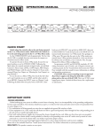
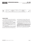
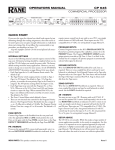
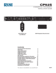
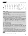
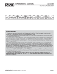
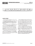
OPERATORS MANUAL MQ 302L STEREO GRAPHIC EQUALIZER QUICK START If this is your first equalizer, please do yourself and your speakers a favor and read at least the first five pages. “An ounce of prevention...,” and all that. The MQ 302L is a stereo equalizer, so adjusting any slider affects both channels simultaneously. Begin by setting all sliders to their center detent (0 dB), and the INPUT LEVEL to its center detent (0 dB). Try to make more cuts than boosts. After equalizing, use the EQ switch to compare equalized and non-equalized signal. While EQ is switched to ACTIVE (out), adjust the INPUT LEVEL to the same level as when EQ is switched to BYPASS (in). You may use either the XLR or ¼" connectors for Inputs or Outputs. Connect only one INPUT type per channel. The XLR and ¼" TRS inputs do not sum. You may, however, use both types of OUTPUTS simultaneously if desired. WEAR PARTS: This product contains no wear parts. Manual-1 INPUT LEVEL control and indicators This controls the overall level. 0 dB gain is reached at the center detent with all sliders centered at their 0 dB detents. Set the INPUT LEVEL to give equal volumes with the EQ switched to ACTIVE or BYPASS, after setting the sliders (see EQ BYPASS switch below). Apply sufficient signal to the input to occasionally light the +4 dBu indicator. Flashing of the OL (overload) LED during peaks can be avoided by turning the INPUT LEVEL or boosted Filters down. Filter level slide controls Each of these sliders control the output level of both channels of the 30 bandpass filters. Center position is grounded for guaranteed flat response. EQ BYPASS switch When pressed to BYPASS, the filter sliders have no effect. Since actual unity gain depends on varying slider settings, use the BYPASS switch to determine the unity gain position of the INPUT LEVEL control by comparing ACTIVE and BYPASS volumes. Cable Wiring In agreement with IEC and AES/ANSI standards, XLR wiring convention is pin 2 Positive (hot), pin 3 Negative (cold), and pin 1 Signal ground (for unbalanced use). Pin 1 and the connector case or shell are tied to chassis ground. Manual-2 LEFT & RIGHT INPUTS LEFT & RIGHT OUTPUTS Use either the Balanced XLR or the Unbalanced ¼" TS jacks. Using both types of Outputs are permissible to drive two devices, such as an amplifier and a recorder. Choose between the balanced XLR or the balanced/unbalanced ¼" TRS jacks, but only use one. Inserting a ¼" TS jack will work—however—always use balanced lines especially when connecting cables over 10 feet in length. Consult SOUND SYSTEM INTERCONNECTION on page Manual-6. POWER switch and LED Your basic, straightforward power switch. When the yellow LED is lit, the MQ 302L is ready to go. Manual-3 MQ 302L CONNECTION Exactly where you install your MQ 302L into a sound system significantly affects such things as noise, system headroom, compressor/limiter performance and other factors influencing overall sound quality. Both what and why you are equalizing determines where you install it. We’ll leave the when and who entirely up to you. WHAT AND WHY Tone contouring is accomplished mainly by ear. This you know how to do. Be careful though, not to introduce too much boost to the bass area. Be aware that the MQ 302L is capable of boosting signals up to 12 dB (4 times as large!)—a level at which great care should be taken to prevent seismic disturbances. Optimal gain setting is indicated by the +4 dBu indicator lighting occasionally, while the OL indicator does not light. The MQ 302L can be used to align crossovers and flatten speaker response. The best way to “see” what your sound system is doing, is to use a realtime analyzer. A 1/3-octave realtime analyzer is an accurate means for setting a 1/3-octave equalizer properly. WHERE For tone contouring, the equalizer may be used at any point in the signal chain, such as insert loops in a mixer to equalize a single instrument, sweeten a tape recording, etc. When an equalizer is used for acoustical correction, the equalizer should be one of the last pieces of gear in front of the amplifiers and active crossovers. Here are a few general guidelines useful in deciding exactly where to install the MQ 302L in the system. See Figure 1 on the next page. Downstream of the Compressor Since system EQ is aimed at controlling acoustical problems, install it after any compressor, which is designed to operate on electrical program material. For one thing, the equalizer slider settings will change in each room location, which in turn affects the control voltage and threshold responses of the compressor, rendering it inconsistent. Secondly, large amounts of boost often cause tone differences by causing some frequencies to limit or compress before others. Upstream of the Limiter If a limiter is installed strictly to protect the drivers, then install the limiter just before the power amplifiers. A good limiter leaves the dynamics unchanged until the amplifier reaches driver overload levels. After any System Gain The best configuration is: mixer, compressor/limiter, equalizer, active crossover and power amplifier. Whenever headroom allows, try to take all the gain at the mixer, and run unity levels from there on. This also gives better noise performance from the mixer. Connect the MQ 302L before the amplifier or active crossover. Take any required line gain before the MQ 302L. Avoid taking a lot of gain in the Manual-4 crossover or power amps as this may create noise problems. The MQ 302L operates at unity gain with the INPUT LEVEL control at the 0 dB center detent when sliders average to center (0 dB). You can test this with the EQ BYPASS switch—adjust the INPUT LEVEL control so that volume does not change when switching between ACTIVE and BYPASS. For more information, read RaneNote 135, “Setting Sound System Level Controls,” available from the factory or the Rane website. Send/Receive Loops Mixers, mixer/preamps and the like often provide send/ receive loops for additional effects or EQ, and the MQ 302L works well in this situation. Just be sure to keep input trim or gain controls turned up as far as the mixer input headroom will allow, to avoid taking excessive gain downstream and creating noise problems. OPERATING INSTRUCTIONS The MQ 302L is an accurate, professional quality instrument capable of precise equalization down to a fraction of a dB. You can expect several advantages from your constant-Q equalizer over conventional designs: Moving one slider will not affect neighboring filters as much, so you won’t spend time re-adjusting sliders (we call this “equalizing the equalizer”). You’ll be able to obtain better feedback control without losing sound quality. All sliders maintain smooth, consistent and accurate calibrated control over filter levels, which is especially critical in low-profile equalizer designs. Because of this, the overall EQ adjustment process is significantly easier and more effective. Equalizing a sound system by ear is a very difficult process to achieve successfully, especially in a timely manner. Although the human ear is very sensitive, it is not calibrated, nor consistent, and frankly the odds against a well behaved, clear sound system are very great when tuned by ear. Most people know when a sound system doesn’t sound good, unfortunately they just can’t tell exactly why and where it’s not right. Because of this, we strongly recommend the use of a realtime analyzer to properly equalize your system with the MQ 302L. Forget everything you’ve thought about analyzers and consider this: there’s a newer generation of analyzers which are compact, simple, very easy to operate and surprisingly affordable. Best of all, they can make a drastic improvement in the overall performance of your sound system while saving a great deal of time and effort. A realtime analyzer helps you quickly achieve things nearly impossible by ear: flatten speaker response, minimize feedback, reduce room resonance and achieve accurate crossover alignment. In most cases, simply “normalizing” or “flattening” a sound system is a surprisingly drastic improvement, but don’t stop there: Remember this Rane proverb: “Look, don’t stop, and listen.” Once you have aligned the system by looking at the analyzer, don’t stop at this point. Listen to the music program and make additional adjustments to suit your taste, Figure 1. Stereo Biamp System with Equalizer the type of music and your audience. Fatten the bass, sweeten the highs, brighten the mids. Since you are starting from a “tuned” system, your ear will not be fooled into thinking bass is too high when actually mids are too low, or that highs are too weak when really the mids are too strong. Fact: analyzers don’t have good taste—people do. Analyzers consistently and accurately “tell it like it is,” but ultimately, personal judgment determines what sounds good or appropriate. In fact, final optimum EQ settings, made after analyzer testing, will vary greatly depending on the type of music, sound pressure level, size of the venue and disposition of the audience. Conclusion: To consistently obtain the best sound from your system, use an analyzer and then your ears, in that order. The analyzer supplies the consistency and calibration while your ears supply the good taste. Manual-5 SOUND SYSTEM INTERCONNECTION Rane’s policy is to accommodate rather than dictate. However, this document contains suggestions for external wiring changes that should ideally only be implemented by trained technical personnel. Safety regulations require that all original grounding means provided from the factory be left intact for safe operation. No guarantee of responsibility for incidental or consequential damages can be provided. (In other words, don’t modify cables, or try your own version of grounding unless you really understand exactly what type of output and input you have to connect.) THE ABSOLUTE BEST RIGHT WAY TO DO IT Use balanced lines and tie the cable shield to the metal chassis (right where it enters the chassis) at both ends of the cable. A balanced line requires three separate conductors, two of which are signal (+ and –) and one shield. The shield serves to guard the sensitive audio lines from interference. Only by using balanced line interconnects can you guarantee (yes, guarantee) hum-free results. Always use twisted pair cable. Chassis tying the shield at each end also guarantees the best possible protection from RFI [radio frequency interference] and other noises [neon signs, lighting dimmers]. THE NEXT BEST RIGHT WAY TO DO IT The quickest, quietest and most foolproof method to connect balanced and unbalanced is to transformer isolate all unbalanced connections. Your audio dealer can recommend such a transformer. The goal of transformer adaptors is to allow the use of standard cables. With these transformer isolation boxes, modification of cable assemblies is unnecessary. Virtually any two pieces of audio equipment can be successfully interfaced without risk of unwanted hum and noise. Another way to create the necessary isolation is to use a direct box. Originally named for its use to convert the high impedance, high level output of an electric guitar to the low impedance, low level input of a recording console, it allowed the player to plug “directly” into the console. Now this term is commonly used to describe any box used to convert unbalanced lines to balanced lines. THE LAST BEST RIGHT WAY TO DO IT If transformer isolation is not an option, special cable assemblies are a last resort. The key here is to prevent the shield currents from flowing into a unit whose grounding scheme creates ground loops (hum) in the audio path (i.e., most audio equipment). Do not be tempted to use 3-prong to 2-prong “cheater” adapters to lift grounds. This is a dangerous and illegal practice. It is true that connecting both ends of the shield is theoretically the best way to interconnect equipment – though this assumes the interconnected equipment is internally grounded properly. Since most equipment is not internally grounded properly, connecting both ends of the shield is not often practiced, since doing so can create noisy interconnections. Manual-6 A common solution to these noisy hum and buzz problems involves disconnecting one end of the shield, even though one can not buy off-the-shelf cables with the shield disconnected at one end. The best end to disconnect is a matter of personal preference and should be religiously obeyed; choose inputs or outputs and always lift the side you choose (our drawings happen to disconnect the outputs). If one end of the shield is disconnected, the noisy hum current stops flowing and away goes the hum — but only at low frequencies. A one-end-only shield connection increases the possibility of high frequency (radio) interference since the shield may act as an antenna. Many reduce this potential RF interference by providing an RF path through a small capacitor (0.1 or 0.01 microfarad ceramic disc) connected from the lifted end of the shield to the chassis. The fact that many modern day installers still follow this one-end-only rule with consistent success indicates this and other acceptable solutions to RF issues exist, though the increasing use of digital and wireless technology greatly increases the possibility of future RF problems. See the following page for suggested cable assemblies for your particular interconnection needs. Find the appropriate output configuration from either your mixer output or the MQ 302 output (down the left side), and then match this with the correct balanced or unbalanced input to the MQ 302 or the amplifer (down the right side.) An “off-the-shelf” cable may be available or modifiable. Soldering should only be attempted by those trained in the art. SUMMARY If you are unable to do things correctly (i.e. use fully balanced wiring with shields tied to the chassis at the point of entry, or transformer isolate all unbalanced signals from balanced signals) then there is no guarantee that a hum free interconnect can be achieved, nor is there a definite scheme that will assure noise free operation in all configurations. WINNING THE WIRING WARS • Use balanced connections whenever possible. • Transformer isolate all unbalanced connections from balanced connections. • Use special cable assemblies when unbalanced lines cannot be transformer isolated. • Any unbalanced cable must be kept under ten feet (three meters) in length. Lengths longer than this will amplify the nasty side effects of unbalanced circuitry's ground loops. This information was condensed from Rane Note 110, “Sound System Interconnection”. If you would like the complete note, call or email the factory, download it from Rane's web site (http://www.rane.com) , or ask your dealer for a copy. VARIOUS XLR & ¼" CABLE ASSEMBLIES Manual-7 MOJO GLOSSARY balanced line The recommended method of interconnecting audio equipment. A balanced line requires three conductors: a twisted-pair for the signal (positive and negative) and an overall shield. The shield must be tied to the chassis at both ends for hum-free interconnect. bandwidth Abbr. BW The numerical difference between the upper and lower -3 dB points of an audio band. clipping What occurs when a unit tries to produce a signal larger than its power supply. The signal takes on a flat-topped, or clipped shape. When an amplifier tries to go above its max power, it clips. compressor A signal processing device used to reduce the dynamic range of the signal passing through it. For instance, an input dynamic range of 110 dB might pass through a compressor and exit with a new dynamic range of 70 dB. The modern usage for compressors is to turn down (or reduce the dynamic range of) just the loudest signals. Other applications use compressors to control the creation of sound. When used in conjunction with microphones and musical instrument pick-ups, compressors help determine the final timbre by selectively compressing specific frequencies and waveforms. connectors Audio equipment uses different styles: RCA An unbalanced pin connector commonly used on consumer and some pro equipment; aka phono plug XLR A 3-pin connector common on pro audio equipment. Preferred for balanced line interconnect; aka Cannon plug ¼" TRS 1. Stereo ¼" connector consisting of tip (T), ring (R), and sleeve (S) sections, with T = left, R = right, and S = ground/shield. 2. Balanced interconnect with the pos & neg signal lines tied to T and R respectively and S acting only as an overall shield. 3. Insert loop interconnect with T = send, R = return, and S = ground/shield. [Think: ring, right, return] ¼" TS Mono ¼" connector consisting of tip (T) [signal] and sleeve (S) [ground & shield] for unbalanced wiring. constant-Q equalizer (also constant-bandwidth) The bandwidth remains constant for all boost/cut levels. Since Q and bandwidth are interrelated, the terms are fully interchangeable. decibel Abbr. dB (named after Alexander Graham Bell). The preferred method and term for representing the ratio of different audio levels. Being a ratio, decibels have no units. Everything is relative. So it must be relative to some 0 dB reference point. A suffix letter is added to distinguish between reference points: 0 dBu A reference point equal to 0.775 V +4 dBu Standard pro reference level equal to 1.23 V 0 dBV A reference point equal to 1.0 V -10 dBV Standard reference level for consumer and some pro audio use, equal to 0.316 V. RCA (phono) connectors are a good indicator of units operating at -10 dBV dynamic range The ratio of the loudest signal to the quietest signal in a unit or system as expressed in decibels (dB). expander A signal processing device used to increase the dynamic range of the signal passing through it. Expanders complement compressors. For example, a compressed input dynamic range of 70 dB might pass through a expander and exit with a new expanded dynamic range of 110 dB. Modern expanders usually operate only below a set threshold point, i.e., they operate only on low-level audio. The term downward expander describes this type of application. ground Any electrical reference point for measuring voltage levels. Usually a large conducting body, such as the earth or an electric circuit connected to the earth. Chassis should always be at earth potential. WARNING: SHOCK HAZARD Never use an AC line cord groundlift adapter or cut off the 3rd pin. It is illegal and dangerous. headroom The level in dB between the typical operating level and clipping. For example, a nominal +4 dBu system that clips at +20 dBu has 16 dB of headroom. hum Unwanted sound contaminating audio paths due to EMI (electro-magnetic interference) caused by AC power-lines & transformers getting into unbalanced, poorly shielded, or improperly grounded connecting cables. Hum has a definite smooth (sine wave) repetitive sound based on the harmonics of 50/60 Hz such as 100/ 120 Hz and 150/180 Hz. interpolating Term meaning to insert between two points. If a graphic equalizer’s adjacent bands, when moved together, produce a smooth response without a dip in the center, they are interpolating between the fixed center frequencies. levels Terms used to describe relative audio signal levels: mic-level Nominal signal coming directly from a microphone. Very low, in the microvolts, and requires a preamp with at least 60 dB gain before using with any line-level equipment. line-level Standard +4 dBu or -10 dBV audio levels. instrument-level Nominal signal from musical instruments using electrical pick-ups. Varies widely, from very low mic-levels to quite large line-levels. limiter A compressor with a fixed ratio of 10:1 or greater. The dynamic action prevents the audio signal from becoming larger than the threshold setting. Linkwitz-Riley crossover The most preferred active crossover design. It features steep 24 dB/octave slopes, in-phase outputs, and flat amplitude response. Due to the in-phase outputs the acoustic lobe resulting when both loudspeakers reproduce the crossover frequency is always on-axis (not tilted up or down) and has no peaking. noise 1. Interconnect. Unwanted sounds contaminating audio paths. RFI (radio frequency interference) caused by broadcast signals leaking into unbalanced, poorly shielded, or improperly grounded connecting cables. Also by light dimmers, motor controls and computers. 2. Music. A random mix of audio frequencies not harmonically related, sounding like radio static. polarity A signals electromechanical potential with respect to a reference. For example, a microphone has positive polarity if a positive pressure on its diaphragm results in a positive output voltage. polarity vs. phase shift: polarity refers to a signals reference NOT to its phase shift. Being 180 degrees out-of-phase and having inverse polarity are DIFFERENT things. We wrongly say something is out-of-phase when we mean it is inverted. One occurs over a period of time; the other occurs instantaneously. Q (upper-case) Quality factor. Defined to be the ratio of the center frequency f divided by the bandwidth BW for a bandpass filter. signal-to-noise ratio The ratio in dB between a reference level and the noise floor. For example, a signal-to-noise ratio of 90 dB re +4 dBu, means the noise floor is 90 dB below a +4 dBu ref. unbalanced line An audio interconnect scheme using one wire with an overall shield. The shield must perform two functions: act as the return signal path (ground) and to protect the conductor from noise (shield). Consequently this method is vulnerable to hum & noise problems. unity gain A gain setting of one. The level out equals the level in. ©Rane Corporation 10802 47th Ave. W., Mukilteo WA 98275-5098 TEL (425)355-6000 FAX (425)347-7757 WEB http://www.rane.com Manual-8 All features & specifications subject to change without notice.