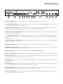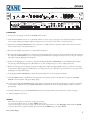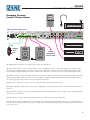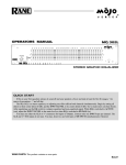
1
CP52S
COMMERCIAL PROCESSOR
INSTALLATION GUIDE
PAGING
INPUT
TRIM
+30
MIC
DETECT
THRESHOLD
8
0
OL
ACTIVE
LIMIT
THRESHOLD
+8
6
2
+60
LINE
PROGRAM INPUT LEVELS
LEVEL
4
10
–3
LINE 1
4
+16
6
LINE 2
4
LINE 3
4
6
6
ZONE
PRIORITY
4
2
–20 +20
DUCKER
DEPTH
6
10
0
10
0
10
0
10
LIMIT
OFF
L2 L3
+
12
LIMIT
THRESHOLD
+8
6
2
8
–3
•
6
0
CP52S
•
0
+16
COMMERCIAL
PROCESSOR
•
6
•
–20 +20
ON
SIG OL
L1
EQ
LEVEL
4
REMOTE
8
0
PROGRAM
SELECT
L2 L3
L1
P
12
10
LIMIT
40
100
250
630
1.6k
4k
10k
POWER
P
PROGRAM SELECT
4
6
2
8
0
10
LEVEL
ZR1 Program and
Level Remote
SCP1S Equalizer Security Cover
Contents
Important Safety Instructions
Quick Start
General Description
CP52S Front Panel
CP52S Rear Panel
CP52S Connections
ZR1 Remote
Recommended Calibration Procedure
Example System: Restaurant and Lounge
Example System: Cardio Fitness Room
Technical Support
Sound System Interconnection
Rane Professional Install Products
Block Diagram
Limited Domestic Warranty
Declaration of Conformity
2
4
5
6
7
8
8
10
14
15
16
17
25
32
33
35
The schematic is downloadable at rane.com/cp52s.html
22274
IMPORTANT SAFETY INSTRUCTIONS
1. Read these instructions.
2. Keep these instructions.
3. Heed all warnings.
4. Follow all instructions.
5. Do not use this apparatus near water.
6. Clean only with a dry cloth.
7. Do not block any ventilation openings. Install in accordance with manufacturer’s instructions.
8. Do not install near any heat sources such as radiators, registers, stoves, or other apparatus (including amplifiers) that produce heat.
9. Do not defeat the safety purpose of the polarized or grounding-type plug. A polarized plug has two blades with one wider than the other. A
grounding-type plug has two blades and a third grounding prong. The wide blade or third prong is provided for your safety. If the provided plug
does not fit into your outlet, consult an electrician for replacement of the obsolete outlet.
10. Protect the power cord and plug from being walked on or pinched particularly at plugs, convenience receptacles, and the point where it exits
from the apparatus.
11. Only use attachments and accessories specified by Rane.
12. Use only with the cart, stand, tripod, bracket, or table specified by the manufacturer, or sold with the apparatus. When a cart is used, use
caution when moving the cart/apparatus combination to avoid injury from tip-over.
13. Unplug this apparatus during lightning storms or when unused for long periods of time.
14. Refer all servicing to qualified service personnel. Servicing is required when the apparatus has been damaged in any way, such as power supply
cord or plug is damaged, liquid has been spilled or objects have fallen into the apparatus, the apparatus has been exposed to rain or moisture,
does not operate normally, or has been dropped.
15. The plug on the power cord is the AC mains disconnect device and must remain readily operable. To completely disconnect this apparatus from
the AC mains, disconnect the power supply cord plug from the AC receptacle.
16. This apparatus shall be connected to a mains socket outlet with a protective earthing connection.
17. When permanently connected, an all-pole mains switch with a contact separation of at least 3 mm in each pole shall be incorporated in the
electrical installation of the building.
18. If rackmounting, provide adequate ventilation. Equipment may be located above or below this apparatus, but some equipment (like large power
amplifiers) may cause an unacceptable amount of hum or may generate too much heat and degrade the performance of this apparatus.
19. This apparatus may be installed in an industry standard equipment rack. Use screws through all mounting holes to provide the best support.
WARNING: To reduce the risk of fire or electric shock, do not expose this apparatus to rain or moisture. Apparatus shall not be exposed to dripping or splashing and no objects filled with liquids, such as vases, shall be placed on the apparatus.
WARNING
CAUTION
RISK OF ELECTRIC SHOCK
DO NOT OPEN
ATTENTION: RISQUE DE CHOCS ELECTRIQUE - NE PAS OUVRIR
To reduce the risk of electrical shock, do not open the unit. No
user serviceable parts inside. Refer servicing to qualified service
personnel.
The symbols shown below are internationally accepted symbols
that warn of potential hazards with electrical products.
This symbol indicates that a dangerous voltage
constituting a risk of electric shock is present
within this unit.
This symbol indicates that there are important
operating and maintenance instructions in the
literature accompanying this unit.
WARNING: This product may contain chemicals known to the State of California to cause cancer, or birth defects or other reproductive harm.
NOTE: This equipment has been tested and found to comply with the limits for a Class B digital device, pursuant to part 15 of the FCC Rules.
These limits are designed to provide reasonable protection against harmful interference in a residential installation. This equipment generates, uses
and can radiate radio frequency energy and, if not installed and used in accordance with the instructions, may cause harmful interference to radio
communications. However, there is no guarantee that interference will not occur in a particular installation. If this equipment does cause harmful
interference to radio or television reception, which can be determined by turning the equipment off and on, the user is encouraged to try to correct
the interference by one or more of the following measures:
• Reorient or relocate the receiving antenna.
• Increase the separation between the equipment and receiver.
• Connect the equipment into an outlet on a circuit different from that to which the receiver is connected.
• Consult the dealer or an experienced radio/TV technician for help.
CAUTION: Changes or modifications not expressly approved by Rane Corporation could void the user's authority to operate the equipment.
This Class B digital apparatus complies with Canadian ICES-003.
2
INSTRUCTIONS DE SÉCURITÉ
1. Lisez ces instructions.
2. Gardez précieusement ces instructions.
3. Respectez les avertissements.
4. Suivez toutes les instructions.
5. Ne pas utiliser près d’une source d’eau.
6. Ne nettoyer qu’avec un chiffon doux.
7. N’obstruer aucune évacuation d’air. Effectuez l’installation en suivant les instructions du fabricant.
8. Ne pas disposer près d’une source de chaleur, c-à-d tout appareil produisant de la chaleur sans exception.
9. Ne pas modifier le cordon d’alimentation. Un cordon polarisé possède 2 lames, l’une plus large que l’autre. Un cordon avec tresse de masse possède 2 lames plus une 3è pour la terre. La lame large ou la tresse de masse assurent votre sécurité. Si le cordon fourni ne correspond pas à votre
prise, contactez votre électricien.
10. Faites en sorte que le cordon ne soit pas piétiné, ni au niveau du fil, ni au niveau de ses broches, ni au niveau des connecteurs de vos appareils.
11. N’utilisez que des accessoires recommandés par Rane.
12. N’utilisez que les éléments de transport, stands, pieds ou tables spécifiés par le fabricant ou vendu avec l’appareil. Quand vous utlisez une valise
de transport, prenez soin de vous déplacer avec cet équipement avec prudence afin d’éviter tout risque de blessure.
13. Débranchez cet appareil pendant un orage ou si vous ne l’utilisez pas pendant un certain temps.
14. Adressez-vous à du personnel qualifié pour tout service après vente. Celui-ci est nécessaire dans n’importe quel cas où l’appareil est abimé : si le
cordon ou les fiches sont endommagés, si du liquide a été renversé ou si des objets sont tombés sur l’appareil, si celui-ci a été exposé à la pluie ou
l’humidité, s’il ne fonctionne pas correctement ou est tombé.
15. La fiche du cordon d’alimentation sert à brancher le courant alternatif AC et doit absolument rester accessible. Pour déconnecter totalement
l’appareil du secteur, débranchez le câble d’alimentation de la prise secteur.
16. Cet appareil doit être branché à une prise terre avec protection.
17. Quand il est branché de manière permanente, un disjoncteur tripolaire normalisé doit être incorporé dans l’installation électrique de
l’immeuble.
18. En cas de montage en rack, laissez un espace suffisant pour la ventilation. Vous pouvez disposer d’autres appareils au-dessus ou en-dessous de
celui-ci, mais certains (tels que de gros amplificateurs) peuvent provoquer un buzz ou générer trop de chaleur au risque d’endommager votre appareil et dégrader ses performances.
19. Cet appareil peut-être installé dans une baie standard ou un chassis normalisé pour un montage en rack. Visser chaque trou de chaque oreille de
rack pour une meilleure fixation et sécurité.
ATTENTION: afin d’éviter tout risque de feu ou de choc électrique, gardez cet appareil éloigné de toute source d’humidité et d’éclaboussures
quelles qu’elles soient. L’appareil doit également être éloigné de tout objet possédant du liquide (boisson en bouteilles, vases,…).
ATTENTION
CAUTION
RISK OF ELECTRIC SHOCK
DO NOT OPEN
ATTENTION: RISQUE DE CHOCS ELECTRIQUE - NE PAS OUVRIR
Afin d’éviter tout risque de choc électrique, ne pas ouvrir l’appareil.
Aucune pièce ne peut être changée par l’utilisateur. Contactez un
SAV qualifié pour toute intervention.
Les symboles ci-dessous sont reconnus internationalement
comme prévenant tout risque électrique.
Ce symbole indique que cette unité utilise un
voltage élevé constituant un risque de choc
électrique.
Ce symbole indique la présence d’instructions
d’utilisation et de maintenance importantes dans
le document fourni.
REMARQUE: Cet équipement a été testé et approuvé conforme aux limites pour un appareil numérique de classe B, conformément au chapitre 15
des règles de la FCC. Ces limites sont établis pour fournir une protection raisonnable contre tout risque d’interférences et peuvent provoquer une
énergie de radiofréquence s'il n'est pas installé et utilisé conformément aux instructions, peut également provoquer des interférences aux niveaux
des équipements de communication. Cependant, il n'existe aucune garantie que de telles interférences ne se produiront pas dans une installation
particulière. Si cet équipement provoque des interférences en réception radio ou télévision, ceci peut être detecté en mettant l'équipement sous/hors
tension, l'utilisateur est encouragé à essayer de corriger cette interférence par une ou plusieurs des mesures suivantes:
• Réorienter ou déplacer l'antenne de réception.
• Augmenter la distance entre l'équipement et le récepteur.
• Connecter l'équipement à une sortie sur un circuit différent de celui sur lequel le récepteur est branché.
• Consulter un revendeur ou un technicien radio / TV expérimenté.
ATTENTION: Les changements ou modifications non expressément approuvés par Rane Corporation peuvent annuler l'autorité de l'utilisateur à
manipuler cet équipement et rendre ainsi nulles toutes les conditions de garantie.
Cet appareil numérique de classe B est conforme à la norme Canadienne ICES-003.
Cet appareil numérique de classe B est conforme à la norme Canadienne NMB-003.
3
CP52S
COMMERCIAL PROCESSOR
PAGING
INPUT
TRIM
+30
MIC
DETECT
THRESHOLD
8
0
OL
ACTIVE
LIMIT
THRESHOLD
+8
6
2
+60
LINE
PROGRAM INPUT LEVELS
LEVEL
4
10
–3
+16
–20 +20
LINE 1
4
6
LINE 2
4
6
LINE 3
4
6
ZONE
PRIORITY
4
DUCKER
DEPTH
6
2
10
0
10
0
10
0
10
OFF
LIMIT
Quick Start
If you were the type that cheated on school book reports by just
skimming through the reading assignments, then this section is
for you! It gives you not quite enough information to really know
what you’re doing. But, if you follow the recommended set up
procedure, you should get at least a “B.”
Keep the amplifiers and the CP52S turned off until all connections are made.
PAGE INPUT
Connect the PAGING INPUT to the Euroblock on the rear
panel. On the front, select the appropriate MIC or LINE switch
position. Then set the gain with the INPUT TRIM control,
then set the PAGING DETECT THRESHOLD and finally the
PAGING LEVEL. MIC PHANTOM POWER, HIGH/LOW
CUT FILTER and PAGE LEVEL TRACKS ZONE LEVEL
switches are located on the rear panel.
PROGRAM INPUTS
Connect line level program sources to the RCA PROGRAM
INPUT jacks (LINE L1, L2, L3 & PRIORITY). If you have a
priority program, like a jukebox, connect it to the PRIORITY
Input. The rear panel PRIORITY switch turns priority override
ON or OFF. The Priority program is automatically selected when
signal is detected at its Input. Set the rear panel PROGRAM
DETECT THRESHOLD and RELEASE TIME as desired.
WEAR PARTS: This product contains no wear parts.
4
EQ
LEVEL
4
REMOTE
8
0
PROGRAM
SELECT
L2 L3
L1
P
LIMIT
THRESHOLD
+8
6
2
8
–3
+16
0
SIG OL
•
6
CP52S
•
0
COMMERCIAL
PROCESSOR
•
6
–20 +20
ON
+
12
10
LIMIT
•
12
40
100
250
630
1.6k
4k
10k
POWER
EXPAND OUTPUT
Wire the EXPAND OUTPUT Euroblock as required to a mono
feed delivering PAGE-only, PROGRAM-only or ZONE (both)
signal depending on the switch setting. This Output uses a crosscoupled line driver and may be used balanced or unbalanced.
Adjust the EXPAND OUTPUT LEVEL trim as desired.
ZONE OUTPUT
The ZONE OUTPUT uses a cross-coupled line driver and may
be used balanced or unbalanced. Set the front panel LIMIT
THRESHOLD as required. Depress the rear panel MONO
switch for a mono Zone.
ZR1 REMOTE
You may use one ZR1 Remote (sold separately) with the CP52S.
Wire it to the ZONE REMOTE Euroblock as indicated. If a
ZR1 remote is not used, any simple switch closure to ground will
work for the D0 and D1 pins. These pins are TTL compatible (0
to 5 VDC). The logic is inverse Gray Code. Any ground referenced 5 volt DC control may be used as the input to Vc. Do not
ground the Vr pin.
READ ME
The CP52S is very versatile. While this makes a large number of
system applications possible, it also results in complexity. For this
reason, it is important to use an organized approach for setup and
calibration. A highly recommended setup is at "Recommended
Calibration Procedure" on page 10. Please follow it to encounter fewer problems and reduce the need to increase our collective
phone bills.
CP52S
COMMERCIAL PROCESSOR
SCP1S Equalizer Security Cover
General Description
The CP52S is a versatile commercial preamplifier designed for
use in restaurants, bars, health clubs and offices. The CP52S
serves one stereo Zone. One gated Paging Input and four stereo
Program Inputs are provided. A Port allows expansion of Page,
Program or Zone signals. Three levels of priority are supported:
1. Page
2. Program Priority
3. Non-Priority Program
The Paging Input is summed after Zone Level, Zone EQ
and Zone Limiter circuits. If the Page Level Tracks Zone Level
switch is on, the Page level tracks the Zone Level.
One of four stereo Program Inputs may be selected. Each line
level Program Input features an independent Level control.
A gated Program Priority Input is provided. When the rear
panel Priority switch is ON and signal is detected at the Priority Input, it overrides any non-priority Program selection. The
detector features adjustableDetect Threshold and Release Time
controls.
Several levels of security are available. The SC 1.7 is an
optional security cover for the entire unit. The SCP1S is an
optional EQ-slider-only security cover. Any front panel control
knobs may be removed and replaced with hole plugs provided
with the SCP1S.
Gated Paging Circuit Features
•
•
•
•
•
•
•
Mic/Line Selection with Gain Trim
Phantom Power Switch
Low / High Cut Filter Switch
Adjustable Detector Threshold with Active LED
Paging Level Control
Switchable Page Level Tracks Zone Level
Page Input Servo-Locked™ Limiter
Zone Output Features
•
•
•
•
•
•
Level Control
1 of 4 Program Select
Ducker On/Off with Depth Control
Output Servo-Locked™ Limiter
7-Band Equalizer (±12 dB)
Wired Zone Remote Port for Level and Program Selection
Special Features
•
•
•
•
Page Initiated Program Ducking
Gated Stereo Program Priority Input
Page/Program/Zone Expansion with Level Control
Universal internal switching power supply (100-240 VAC)
5
CP52S Front Panel
1
3
6
INPUT
TRIM
DETECT
THRESHOLD
3
9 11
PAGING
+30
MIC
2
8
0
OL
ACTIVE
4
5
LIMIT
THRESHOLD
+8
6
2
+60
LINE
PROGRAM INPUT LEVELS
LEVEL
4
10
13
–3
+16
–20 +20
LINE 1
4
6
LINE 2
4
LINE 3
4
6
6
ZONE
PRIORITY
4
DUCKER
DEPTH
6
2
PROGRAM
SELECT
L2 L3
L1
P
10
0
0
10
10
0
10
OFF
8
–3
+16
0
+
12
•
6
CP52S
•
0
COMMERCIAL
PROCESSOR
•
6
–20 +20
SIG OL
10
LIMIT
THRESHOLD
+8
6
2
ON
LIMIT
8
EQ
LEVEL
4
REMOTE
8
0
14
10
LIMIT
•
12
40
12
100
250
630
1.6k
4k
10k
15
POWER
16
1 PAGING INPUT TRIM control adjusts the Page Input preamplifier gain to match the microphone / source in use. The range is
30 dB to 60 dB.
2 PAGING INPUT MIC / LINE switch selects a 30 dB Input pad when set to LINE. Phantom Power is disabled when LINE is
selected.
3 PAGING DETECT THRESHOLD sets the Page signal level required to gate a Page on and illuminate the ACTIVE indicator
(see 5). The range is -∞ (on) to +4 dBu.
4 PAGING OL (Overload) indicator lights when the Page Input preamplifier comes within 3 dB of clipping.
5 PAGING ACTIVE indicator lights when the Page signal level reaches the PAGING DETECT THRESHOLD. A Page is always
Active when the PAGING DETECT THRESHOLD is set to minimum (ccw).
6 PAGING LEVEL control adjusts the Paging Level in the Zone.
7 PAGING LIMIT THRESHOLD control sets the maximum output level for a Page. This is a true voltage Limiter circuit with a
ratio of 15:1. The Threshold range is -20 dBu to +20 dBu. The LIMIT indicator lights during limiting.
8 PROGRAM INPUT LEVELS allow independent adjustment of level for each Program Input.
9 ZONE DUCKER DEPTH control sets the Ducker Depth (the amount of Program attenuation during a Page) from 50 dB (ccw)
to 6 dB (cw). The Ducker release is ramped.
0 ZONE DUCKER OFF / ON switch turns the Ducker ON or OFF.
q ZONE PROGRAM SELECT switch assigns one of four Program Inputs to the Zone Output, only when w is out.
w ZONE REMOTE switch, when pushed in, turns control of Zone Level and Zone Program Selection over to the Zone Remote
Port. Front panel ZONE LEVEL and ZONE PROGRAM SELECT controls are inactive when REMOTE is selected. An optional
wired ZR1 remote may be connected to the Zone Remote Port. An object smaller in diameter than the switch button is required to
engage the REMOTE switch.
e ZONE LEVEL control adjusts the overall Level for the Zone Output. If the rear panel PAGE LEVEL TRACKS ZONE LEVEL
switch is ON, this control also effects the Paging Level. ZONE SIG and OL indicators assist in setting the LEVEL control, illuminating with Signal present at -20 dBu and Overload at +16 dBu (4 dB before clipping) respectively.
r ZONE LIMIT THRESHOLD control sets the maximum level for the Zone Output. This is a true voltage Limiter circuit with a
ratio of 15:1. The Threshold range is -20 dBu to +20 dBu. The LIMIT indicator lights during Limiting.
t Graphic Equalizer controls are “stereo,” with each slider controlling the response of both Left and Right channels. These controls
allow ±12 dB adjustment of seven ISO center frequencies on 11/3 -octave centers.
y POWER indicator illuminates when the CP52S is connected to a proper power source.
6
CP52S Rear Panel
CP52S
COMMERCIAL AUDIO
EQUIPMENT 24TJ
100-240 V
50/60 Hz 12 WATTS
R
ZONE REMOTE
PROGRAM
D1 D0
LEVEL
MIN
MAX
Vr Vc
ZONE OUTPUT
RIGHT
+
–
EXPAND OUTPUT
LEFT
+
–
EXPAND
MONO
+
–
LEVEL
PRIORITY
RELEASE
5
ZONE PAGE
MADE IN U.S.A. RANE CORP.
15
D1 D0
Vr Vc
14
+
–
+
13
–
+
–
12 11
DETECT
THRESHOLD
SOURCE
SEC
20
PROGRAM
2
INPUTS
PAGING INPUT
1
L
R
OFF
R
PAGE LEVEL
TRACKS
ZONE LEVEL
OFF
ON
ON
LOW / HIGH
CUT
FILTER
OUT
IN
100 Hz / 7 kHz
MIC
PHANTOM
POWER
OFF
9
8 7 6
5
4
3
INPUT
+
–
+
–
ON
+15V
ALL AUDIO AND REMOTES ARE CLASS 2 WIRING
PROGRAM
10
3
L
2
1
1 PAGING INPUT Euroblock connector may be wired per instructions in"CP52S Connections" on page 8.
2 MIC PHANTOM POWER switch, when ON, enables +15 volt Phantom Power to the PAGING INPUT connector. If the front
panel LINE switch is selected, Phantom Power is defeated.
3 LOW / HIGH CUT FILTER switch, when IN, limits the bandwidth of the Paging Input from 100 Hz to 7 kHz, improving
intelligibility in some installations. The Paging detector is always bandlimited to 100 Hz to 7 kHz.
4 PAGE LEVEL TRACKS ZONE LEVEL switch, when ON, forces the Paging level to track the Zone level. When OFF, Paging
level and Zone level are independent.
5 Four PROGRAM INPUTS are provided. Three are non-priority Inputs — the fourth is a Program PRIORITY Input. When
signal is detected at this Input, it is automatically selected as the Program Input source regardless of the front panel PROGRAM
SELECT setting.
6 PRIORITY DETECT THRESHOLD control allows adjusting the threshold from -∞ (signal on) to -35 dBu (typ). The factory
setting is -50 dBu.
7 PRIORITY OFF/ON switch allows disabling the automatic priority override function when in the OFF position.
8 PRIORITY RELEASE TIME control sets the delay time from last detected signal to release of automatic priority override. The
range of control is 5 seconds (ccw) to 20 seconds (cw).
9 EXPAND LEVEL trim adjusts the signal level delivered to the ZONE EXPAND OUTPUT.
0 EXPAND SOURCE switch assigns PAGE-only, PROGRAM-only or full ZONE (both) as the source for the Expand Output.
q EXPAND OUTPUT features a balanced line driver with a Euroblock connector. This mono Output may be wired balanced or
unbalanced per the instructions in "CP52S Connections" on page 8.
w ZONE MONO switch, when pressed in, sums the left and right signals to provide a mono Zone signal available at both Left and
Right Outputs.
e ZONE OUTPUT Port features a balanced line driver with a Euroblock connector. These Left and Right Outputs may be wired
balanced or unbalanced per the instructions in"CP52S Connections" on page 8.
r ZONE REMOTE Port provides the wiring interface for the optional ZR1 wired remote. The ZR1 remote provides remote control of Zone Level and Zone Program Select functions. See "ZR1 Remote" on page 8.
t Universal Voltage Input: via a miniature IEC 60320 C6 appliance inlet. This mates with an IEC 60320 C5 line cord (USA
domestic). Do not lift the ground connection!
7
CP52S
COMMERCIAL PROCESSOR
CP52S Connections
ZR1 Remote
All Input and Output connections are made with Euroblock
connectors except for the RCA Program Inputs. When wiring
to Euroblocks, a minimum wire gauge of 22 is preferred for
reliability. If the ground or shield wire is left shorter, it acts as
a strain relief for the other wires. Cable with a flexible jacket is
easier to use and less likely to damage the connections. Avoid
stripping excess insulation. Inspect wires for nicks that may lead
to wire breakage. Fully insert each wire in the appropriate socket
and tighten the screw.
The Page Input is a true instrumentation amplifier and operates balanced or unbalanced. Expand and Zone Outputs are
driven by high quality cross-coupled line drivers and operate balanced or unbalanced. Wiring is usually the same for both Inputs
and Outputs. Balanced operation is recommended, and necessary when wire lengths are greater than 10 feet (3 meters). Balanced wiring is logical, (+) to (+), (–) to (–) and shield to shield.
For unbalanced operation, we recommend using two conductor cable with shield. The cable is wired to the CP52S the same
as for balanced operation. At the other end of the cable, connect
the (+) wire to signal “hot,” and both the (–) and shield wires to
ground (important).
If you use single conductor cable with shield, connect the
shield/gnd wire to both the (–) and shield pins at the CP52S. At
the other end of the cable connect the (+) wire to the signal “hot”
and the shield/gnd wire to ground. When unbalanced wiring is
used, it is very important for the CP52S and any other unit in
the system to have good earth or technical grounds. If a unit is
located more than 10 feet (3 meters) away from the CP52S or
is of a type that might create grounding problems, use isolation
transformers.
When connecting any CP52S Output as unbalanced, use (+)
and ground — leave (–) floating.
Depending on building grounding, an occasional source of
system hum is powering sources and amplifiers on different electrical circuits. Try connecting everything on the same circuit.
Refer to the included RaneNote, "Sound System Interconnection" on page 17 for more information on proper wiring
procedures.
The CP52S supports a wired remote for Zone Level and Zone
Source selection. Wire lengths of up to 1000 feet (300 meters) are
possible. A brief list of suitable wire types is provided here in the
Wire Types section.
The ZR1 remote provides Zone Level and Source Selection,
allowing local control from inside the Zone. If only one of the
two controls is used, you may wish to remove the unused knob
and cover the hole with one of the plugs provided in the kit. If
you require one ZR1 remote to control more than one unit, simply wire the ports in parallel. This may be done with the Selector
only, Level only or both.
Be sure Power to the CP52S is off while all remote connections are made. It is important to ensure that the CP52S Remote
Port is not subjected to sustained voltages outside the range of 0
to 5 volts DC or high levels of static. Inputs are protected—however, caution is the better part of... you know. It is a good idea to
install the wiring, connect it to the remote assemblies and then
make the final connections at the CP52S. Do not short the Vr
pin to ground. Although the pin is current limited, excess heat
will be generated in the 5 volt supply if a short occurs. Never
subject the Vr pin to voltages above 5V.
If a ZR1 remote is not used, any simple switch closure to
GND will work for the D0 and D1 pins. These pins are TTL
compatible (0 to 5 VDC). The logic is inverse Gray Code. Any
ground referenced 5 volt DC control may be used as the input to
Vc. Do not ground the Vr pin.
CP52S
COMMERCIAL AUDIO
EQUIPMENT 24TJ
100-240 V
50/60 Hz 12 WATTS
R
ZONE REMOTE
PROGRAM
D1 D0
LEVEL
MIN
MAX
Vr Vc
ZONE OUTPUT
RIGHT
+
–
EXPAND OUTPUT
LEFT
+
–
EXPAND
MONO
+
–
LEVEL
PRIORITY
RELEASE
ZONE PAGE
8
D1 D0
Vr Vc
+
–
+
–
+
–
DETECT
THRESHOLD
SOURCE
5
MADE IN U.S.A. RANE CORP.
Remote Selector
11=LINE 1
10=LINE 2
00=LINE 3
01=PRIORITY
PROGRAM
SEC
20
3
L
R
OFF
Remote Volume
2 kΩ pot, reverse-log taper
Or any GND referenced 0-5 VDC.
Attenuation=64 mV/dB.
Range 0V to +5V (0 to -87 dB).
PROGRAM
2
INPUTS
PAGING INPUT
1
L
R
ON
ALL AUDIO AND REMOTES ARE CLASS 2 WIRING
PAGE LEVEL
TRACKS
ZONE LEVEL
OFF
ON
LOW / HIGH
CUT
FILTER
OUT
IN
100 Hz / 7 kHz
MIC
PHANTOM
POWER
OFF
INPUT
+
–
+
–
ON
+15V
CP52S
COMMERCIAL PROCESSOR
S1B
10
PROGRAM SELECT
Zone / Level
4
6
0
10
2
8
LEVEL
D0
1
S1A
5
2
3
CW
3
ZR1
P
D1
Vc
4
2
4
3
2
1
GND
GND
R1
2KRD
1
L1
Decora plate (not included)
J1A
L2 L3
9
8
7
6
GND
Vr
5
5 POS TERM
ZONE REMOTE (ZR 1)
assembly and silk-screened front panel to the electrical box (see
diagram, next page). Note the “UP” arrow screened on the
printed circuit board of the remote (mount it pointing up).
Install each knob so that the line on the knob is properly
aligned with the silk-screening on the front panel of the remote
assembly. Install any Decora plate of your choice. For a secured
installation, you may wish to leave the knobs off and use a blank
Decora plate to cover the remote after adjustment.
VR1
Level
LEVEL
4
6
0
10
2
8
VR1 LEVEL REMOTE
Rane provides the VR1 Volume Remote for applications that require a remote level control without the program selector found
in the ZR1. It contains the same 2k RD taper pot, and connects
as shown in the ZR1 schematic.
With the front panel REMOTE switch, all selection and level is done either on the front panel or at the remote; never both
locations. Connecting just a VR1 to the CP52S remote control
terminals will allow level adjustment. However without a source
selector, the unit will default to source one. If the PRIORITY
/ L4 INPUT automatic switching is enabled, then the unit will
select the L4 signal when present and L1 at any other time. Thus
if only a jukebox (P/L4) and other line source (L1) are used, the
remote volume control will work just fine.
REMOTE MOUNTING
The ZR1 or VR1 remote assembly mounts in a standard U.S.
electrical box with a minimum depth of 2.25". Be sure to note
the wire color of each input in order to facilitate correct wiring to the CP52S. Connect each wire to the connector by fully
inserting it in the correct socket and tightening the screw. Make
sure the cable jacket is stripped back sufficiently to allow it to lie
in the electrical box with the remote assembly inserted. Use the
flat head #6 screws supplied with the kit to mount the remote
WIRE TYPES
Though variations in wire type do not greatly affect the performance of the remote controls, 22-gauge stranded wire with a
flexible jacket is recommended. You may use 5-conductor unshielded remote control signal cable for short runs (less than 200
feet [60 meters]) or 4-conductor (2 pair) shielded remote control
signal cable (use the shield as the ground return) for long runs
(200 to 1000 feet [60 to 300 meters]). The type of wire required
is influenced by your installation and local electrical codes.
Rane Corporation does not provide or source cable. Please
contact your local retail or wholesale outlet, not the factory. The
following is a short list of suitable cable types:
CONSOLIDATED ELECTRONIC WIRE AND CABLE
Plenum cable:
Unshielded remote control signal cable CAT. # 9896
Shielded remote control signal cable CAT. #9877, CAT. #9852
WEICO WIRE & CABLE INC.
Communication and control cable:
Multiconductor, unshielded CAT. #7606
ALPHA
Communication and control cable:
Multiconductor, unshielded CAT. #1175C
BELDEN
Unshielded remote control signal cable CAT. # 88741
Shielded remote control signal cable CAT. # 88723
9
Recommended Calibration Procedure
The CP52S is a very versatile instrument. While this allows it to conform to the requirements of a large number of system applications, it also results in complexity. For this reason, it is very important to use an organized approach to system calibration. Once the
system is connected, take the time for proper calibration. The following is an ordered list of system adjustments to make calibration
easy with optimum performance results.
This procedure assumes that a microphone is used for the Page. The procedure (except for the exact wording) is the same for other
Page sources.
Make sure the POWER is off!
PAGING
INPUT
TRIM
+30
MIC
DETECT
THRESHOLD
8
0
–3
10
+16
–20 +20
COMMERCIAL AUDIO
EQUIPMENT 24TJ
100-240 V
50/60 Hz 12 WATTS
R
LINE 1
4
6
LINE 2
4
LINE 3
4
6
6
ZONE
PRIORITY
4
DUCKER
DEPTH
6
2
ZONE REMOTE
PROGRAM
D1 D0
0
10
0
0
10
10
0
10
OFF
LEVEL
MIN
MAX
Vr Vc
ZONE OUTPUT
–
Vr Vc
+
–
8
–3
0
EXPAND OUTPUT
LEFT
+
–
EXPAND
MONO
+
–
LEVEL
+
–
+
–
DETECT
THRESHOLD
SOURCE
20
OFF
COMMERCIAL
PROCESSOR
•
6
•
12
LIMIT
3
CP52S
•
0
+16
10
PRIORITY
RELEASE
SEC
•
6
–20 +20
ON
ZONE PAGE
D1 D0
2
+
12
LIMIT
THRESHOLD
+8
6
SIG OL
RIGHT
+
EQ
LEVEL
4
REMOTE
8
5
MADE IN U.S.A. RANE CORP.
PROGRAM
SELECT
L2 L3
L1
P
LIMIT
ACTIVE
OL
CP52S
LIMIT
THRESHOLD
+8
6
2
+60
LINE
PROGRAM INPUT LEVELS
LEVEL
4
40
PROGRAM
2
INPUTS
100
L
R
R
630
PAGE LEVEL
TRACKS
ZONE LEVEL
OFF
ON
ON
LOW / HIGH
CUT
FILTER
OUT
IN
100 Hz / 7 kHz
ALL AUDIO AND REMOTES ARE CLASS 2 WIRING
PROGRAM
PREFLIGHT CONTROL SETTINGS
PAGING SETTINGS:
• MIC/LINE Pad
• INPUT TRIM
• DETECT THRESHOLD
• PAGING LEVEL
• LIMIT THRESHOLD
• MIC PHANTOM POWER
• LOW / HIGH CUT FILTER
• PAGE LEVEL TRACKS ZONE LEVEL
As required
12:00 (center)
Min (ccw, Active)
Min
+20 dBu
As required
As required
OFF (front panel)
(front panel)
(front panel)
(front panel)
(front panel)
(rear panel)
(rear panel)
(rear panel)
PROGRAM INPUT SETTINGS:
• Input Levels
• PRIORITY DETECT THRESHOLD
• PRIORITY RELEASE TIME
• PRIORITY OFF / ON
Min
Set to -50 dBu at factory
Set to 12 sec. at factory
OFF
(front panel)
(range -∞ to -35 dBu; rear panel)
(range 5 to 20 sec; rear panel)
(rear panel)
ZONE SETTINGS:
• DUCKER DEPTH
2:00 (about 15 dB)
(front panel)
• DUCKER OFF / ON
OFF
(front panel)
LINE 1, 2, 3 or P
(Any active Input; front panel)
• PROGRAM SELECT
Out (local control)
(front panel)
• REMOTE
Max
(front panel)
• Zone LEVEL
+20 dBu
(front panel)
• LIMIT THRESHOLD
• EqualizerFlat(front panel)
As required (rear panel)
• Zone Output MONO
As required
(rear panel)
• Expand ZONE/PROGRAM/PAGE
SYSTEM CONNECTIONS
• Connect page microphone or line level paging source
• Connect Program sources
• Connect Output to amps
• Connect ZR1 Remote control (if required)
...You are now ready to calibrate the CP52S (continued on next page...)
10
1.6k
4k
POWER
10k
PAGING INPUT
1
L
250
MIC
PHANTOM
POWER
OFF
INPUT
+
–
+
–
ON
+15V
CP52S
COMMERCIAL PROCESSOR
PAGING
INPUT
TRIM
+30
MIC
DETECT
THRESHOLD
8
0
–3
10
+16
–20 +20
COMMERCIAL AUDIO
EQUIPMENT 24TJ
100-240 V
50/60 Hz 12 WATTS
R
LINE 1
4
6
LINE 2
4
LINE 3
4
6
6
ZONE
PRIORITY
4
DUCKER
DEPTH
6
2
ZONE REMOTE
PROGRAM
D1 D0
0
10
0
0
10
10
0
10
OFF
LEVEL
MIN
MAX
Vr Vc
RIGHT
–
Vr Vc
+
–
8
LEFT
+
–
EXPAND
MONO
+
–
LEVEL
ON
0
+
–
+
–
0
+16
RELEASE
DETECT
THRESHOLD
SOURCE
20
OFF
COMMERCIAL
PROCESSOR
•
6
•
12
LIMIT
3
CP52S
•
10
PRIORITY
SEC
–3
•
6
–20 +20
EXPAND OUTPUT
ZONE PAGE
D1 D0
2
+
12
LIMIT
THRESHOLD
+8
6
SIG OL
ZONE OUTPUT
+
EQ
LEVEL
4
REMOTE
8
5
MADE IN U.S.A. RANE CORP.
PROGRAM
SELECT
L2 L3
L1
P
LIMIT
ACTIVE
OL
CP52S
LIMIT
THRESHOLD
+8
6
2
+60
LINE
PROGRAM INPUT LEVELS
LEVEL
4
40
PROGRAM
2
INPUTS
100
L
R
R
PAGE LEVEL
TRACKS
ZONE LEVEL
OFF
ON
ON
PROGRAM
630
1.6k
4k
POWER
10k
PAGING INPUT
1
L
250
ALL AUDIO AND REMOTES ARE CLASS 2 WIRING
LOW / HIGH
CUT
FILTER
OUT
IN
100 Hz / 7 kHz
MIC
PHANTOM
POWER
OFF
INPUT
+
–
+
–
ON
+15V
CALIBRATION
1. Connect the power supply and verify the POWER indicator lights.
2. Verify the Zone LEVEL control is set to maximum and that an active source is playing for each of the Program Inputs intended
for use. Select each Program Input and adjust its Input Level control to be the very loudest you would ever desire.
3. Adjust the Zone LIMIT THRESHOLD so that it just starts to audibly reduce the output level. This ensures that the level will
never be louder than the maximum level just set.
4. Turn the Zone LEVEL control down to a comfortable listening level.
5. Note that with the Paging LEVEL set to minimum, the following Page will not be heard. Speak very loudly (bark) into the Paging
mic. Adjust the INPUT TRIM control so that the Paging Overload indicator just lights. It is important to set the gain of the preamp before setting the Paging Detect Threshold.
6. Speak into the Paging mic in a normal voice and adjust the Paging DETECT THRESHOLD so the ACTIVE indicator lights
only during speech. If the Paging Detect Threshold is set too low, the Pager may gate on due to background sound.
7. With an active Program source playing, speak into the Paging mic. Adjust the Paging LEVEL control to provide the correct Pageto-Program mix. If the Paging Detect Threshold is set too high, there may be a delay before speech is heard. To correct this, lower
the Paging Detect Threshold setting.
8. Set the Paging LIMIT THRESHOLD to limit the maximum Page level to the loudest desired volume.
9. Set the DUCKER switch to ON. With an active Program source playing, speak into the Page mic and adjust the DUCKER
DEPTH to the desired level of Program during a Page.
10. Set the rear panel Program PRIORITY OFF / ON switch as required. If an automatic Program Priority override is not required,
set this switch to OFF. The front panel PROGRAM SELECT switch will select the “P” Program Input just like any other nonpriority Input.
11. If using a ZR1 Remote, press the ZONE REMOTE switch in and verify that the remote functions correctly (see page 6).
12. Adjust the Equalizer as desired.
SECURITY
Rane offers a few options to protect the settings you just made.
To protect the equalizer section, use a Rane SCP1S security cover.
To protect the setting of any rotary control, remove the knob and replace with one of the hole plugs included with the SCP1S.
To protect the entire front panel and allow operation with only the ZR1 Remote, use a Rane SC 1.7.
You’re all set. Enjoy.
11
CP52S
COMMERCIAL PROCESSOR
Specifications
Parameter
MIC/LINE PAGING INPUT
..........Input Type
..........RFI Filter
..........Gain range
..........Frequency Response
..........Input Referred Noise
..........CMRR
..........THD+NS
Specification
..........Phantom Power
..........“Mic” Input impedance
..........Line Pad
..........“Line” Input impedance
..........Signal Detector Attack
..........Signal Detector Release
..........Overload Detector
..........Low Cut / Hi Cut Filters
..........Paging Zone Level Adjust
..........Page Limiter: Threshold Range
...............Attack Time
...............Release Time
...............Ratio
PROGRAM INPUTS
..........Number of Inputs
..........Input Type
..........Input Level Adjust
..........Frequency Response
..........Input Impedance
..........Priority Program Input
...............Input Detector Range
...............Release Time Range
...............Attack Time
+15
500
30
14.5k
10
3
+16
100 & 7k
Off to 0
-20 to +20
20
250
15:1
12
Balanced
Yes
+30 to +60
30 to 40k
-125
40
.05
Four
Unbalanced
Off to 0
10 to 50k
10k
5 to 20
50
Limit
Units
Conditions/Comments
Instrumentation amplifier
2
typ
1
min
.01
dB
Hz
dBu
dB
%
4%
1%
1
1%
typ
typ
1
5
VDC
Ω
dB
Ω
msec
sec
dBu
Hz
dB
dBu
msec
msec
typ
typ
typ
typ
Continuously adjustable
Maximum gain, +0, -3 dB
Gain: 60 dB, Rs:150 Ω, BW: 20 kHz
20 Hz to 20 kHz
Gain: 30 dB, +4 dBu out, 1 kHz, BW: 80
kHz
Each leg to ground
Defeats phantom power
Each leg to ground
Fixed; 10 dB overdrive
Fixed
4 dB before clipping
Selectable In/Out
Continuously adjustable
For a 10 dB step; fixed
For a 10 dB step; fixed
Soft knee
All controls duplicated for each input
Stereo
RCA connector
typ
20
dB
Hz
Ω
+0, -3 dB
typ
typ
typ
dBu
sec
msec
On rear panel; factory set to -50 dBu
On rear panel; factory set to 15 seconds
For a 20 dB step; fixed
CP52S
COMMERCIAL PROCESSOR
Parameter
OUTPUTS: Type
..........Zone Out Gain: Program In
...............From Page Inputs
..........Expand Out Gain: Zone
...............From Page or Program In
..........Frequency Response
..........S/N
..........THD+N
..........Crosstalk
..........Output Impedance
..........Zone Maximum Output
..........Expand Maximum Output
..........Signal Present
..........Overload Detector
..........Ducker: Depth Range
...............Ramped Release
..........Limiter: Threshold Range
..............Attack Time
..............Release Time
..............Ratio
EQUALIZER: Boost/Cut Range
..........ISO Center Frequencies
UNIT: Maximum Power
..........Universal Line Voltage
..........Conformity
..........Construction
..........Size
..........Weight
SHIPPING: Size
..........Weight
Note: 0 dBu = 0.775 Vrms
Specification
Balanced
16
6
16
6
10 to 40k
84
.1
-75
100
20
24
-20
+16
-50 to -6
10
-20 to +20
20
250
15:1
±12
1 1/3
12
100-240
CE, FCC, CULUS
All Steel
1.75"H x 19"W x 8.5"D
5 lb
4.5" x 20.3" x 13.75"
9 lb
Limit
Units
1
1
1
1
typ
min
max
max
1%
typ
typ
typ
typ
typ
typ
typ
typ
typ
typ
.5
typ
dB
dB
dB
dB
Hz
dBr
%
dB
Ω
dBu
dBu
dBu
dBu
dB
sec
dBu
msec
msec
dB
oct
W
VAC
Conditions/Comments
Euroblock connector
100 kΩ load
100 kΩ load
+0, -3 dB
re +4 dBu; BW: 20 Hz-20 kHz
+4 dBu, 1 kHz, BW: 80 kHz
1 kHz, Rs: 25 Ω, (L/R)
Each leg
RL: 600Ω
RL: 2 kΩ
Maximum
4 dB before clipping
Continuously adjustable
To full output level
Continuously adjustable
For a 10 dB step; Fixed
For a 10 dB step; Fixed
Soft knee
50/60 Hz
1U (4.4 cm x 48.3 cm x 21.6 cm)
(2.3 kg)
(11.5 cm x 52 cm x 35 cm)
(4.1 kg)
13
CP52S
COMMERCIAL PROCESSOR
Example System:
Restaurant and Lounge
CD JUKEBOX
STREAMING
MUSIC SERVICE
11 17 70:00
MENU
MP3 PLAYER
12:00
PRIORITY 2
CP52S
COMMERCIAL AUDIO
EQUIPMENT 24TJ
100-240 V
50/60 Hz 12 WATTS
R
ZONE REMOTE
PROGRAM
D1 D0
LEVEL
MIN
MAX
Vr Vc
ZONE OUTPUT
RIGHT
+
EXPAND OUTPUT
LEFT
–
+
–
EXPAND
MONO
+
LEVEL
RELEASE
5
ZONE PAGE
MADE IN U.S.A. RANE CORP.
D1 D0
Vr Vc
+
–
+
–
+
DETECT
THRESHOLD
SOURCE
–
–
CABLE TV
PRIORITY
SEC
20
OFF
3
PROGRAM
2
INPUTS
PAGING INPUT
1
L
L
R
R
ON
PAGE LEVEL
TRACKS
ZONE LEVEL
OFF
ON
LOW / HIGH
CUT
FILTER
MIC
PHANTOM
POWER
OUT
IN
100 Hz / 7 kHz
OFF
–
+
–
ON
+15V
ALL AUDIO AND REMOTES ARE CLASS 2 WIRING
PROGRAM
INPUT
+
MA3
MULTICHANNEL
AMPLIFIER
1
0
3
2
0
3
0
3
POWER
3
6
6
6
12
12
12
PRIORITY 1
MIC
MA 3
MULTICHANNEL
AMPLIFIER
dB
CHANNEL OUTPUT HEADROOM
ZR1
8Ω
L1
L2 L3
P
PROGRAM SELECT
4
6
0
10
2
8
LEVEL
POWER
-ORFrom a CP64S or
CP52S Expand Output
(Page or Program)
8Ω 70V
PROGRAM
SELECT
LEVEL
LEFT RIGHT
ZONE 1
LOUNGE
DISTRIBUTED
RESTAURANT
RECEPTION
STATION
This restaurant has a paging mic from reception, 4 music sources, a remote for source selection and volume control within the lounge.
Program Source - Allows the use of up to 4 stereo sources such as TV audio or a Music service.
Jukebox - This Input allows the Jukebox to automatically override the selected Program source when it is turned on.
Multichannel Amplifiers - The MA 4 is 4 channels @ 100W 8 ohms, or use the MA 3 with 3 channels @ 40W 8 ohms.
Page - will automatically duck the chosen program material. It has first priority.
ZR1 Zone Remote - Allows remote control of Program Selection and Zone Level within the restaurant or lounge.
Zone 1 - Can be stereo in the lounge.
Zone 2 - Is mono in the restaurant, using a MT 4 or MT 6 for transformer distribution to 70V or 25V speakers.
14
CP52S
COMMERCIAL PROCESSOR
Example System:
Cardio Fitness Room
MP3
Player
MENU
Wireless Mic Receiver
CP52S Commercial Processor
CP52S
COMMERCIAL AUDIO
EQUIPMENT 24TJ
100-240 V
50/60 Hz 12 WATTS
R
ZONE REMOTE
PROGRAM
D1 D0
LEVEL
MIN
MAX
Vr Vc
ZONE OUTPUT
RIGHT
+
–
EXPAND OUTPUT
LEFT
+
–
EXPAND
MONO
+
–
LEVEL
PRIORITY
RELEASE
5
ZONE PAGE
MADE IN U.S.A. RANE CORP.
D1 D0
Vr Vc
+
–
+
–
+
–
DETECT
THRESHOLD
SOURCE
SEC
20
OFF
3
PROGRAM
2
INPUTS
L
R
R
L1
L2 L3
P
4
6
0
10
2
8
PAGE LEVEL
TRACKS
ZONE LEVEL
OFF
ON
PROGRAM
ON
LOW / HIGH
CUT
FILTER
OUT
IN
100 Hz / 7 kHz
MIC
PHANTOM
POWER
OFF
INPUT
+
–
+
–
ON
+15V
ALL AUDIO AND REMOTES ARE CLASS 2 WIRING
Streaming Music Service
ZR1
PROGRAM SELECT
PAGING INPUT
1
L
PROGRAM
SELECT
Feed to
Background
Music System
LEVEL
LEVEL
Powered
Speaker
Powered
Speaker
CD Player
MENU
DVD or TV Audio
The CP52S offers a few features not found in other aerobic room rack mixers.
All the instructor needs is to turn on the the headset, and start an MP3 dock or other source that's plugged into the Priority input.
The source automatically switches to the Priority music source, and switches back when that source is turned off. A wired remote
control (ZR1) can manually change the source or volume from a wall plate, or mounted on the side of the locked equipment rack.
The CP52S can stay in a secure locked rack. This protects the settings and EQ so the instructor can easily learn and know the system
without surprises. When cardio class isn't in session, the CP52S can supply the club background music from the satellite music service to the big speakers in the cardio room at a predetermined input level.
Program Source - Allows the use of up to 4 stereo sources such as TV audio, CD or music service.
MP3 Player - This Priority Input allows a laptop, CD or MP3 player to automatically override the selected Program source when it’s
turned on.
Wireless headset and receiver - can automatically duck the chosen program material by a chosen variable amount, preventing volume
overload to the ears in the class.
ZR1 Zone Remote - Allows remote control of Program Selection and Level to the stereo room speakers.
Expand Output - Though a satellite music service could be one of the inputs, the Expand Output may run to the club background
music system. This allows the music mix to play in the club without the wireless mic signal. A proper hookup assures that both would
not be used at once.
15
CP52S
COMMERCIAL PROCESSOR
Technical Support
How can I hook a fire alarm control relay to the unit for
complete muting?
Connect a normally closed relay across the Paging Inputs
(plus [+] and minus [-]) so they are shorted together. When
an alarm condition exists and the coil becomes energized, the
contacts open and the short is removed. The Paging Input
Detect Threshold must be adjusted such that the noise floor is
sufficient to trigger a paging condition and enable ducking, (i.e.
set the detector just shy of maximum sensitivity – fully counter
clockwise – so shorted turns off the green LED and open causes
it to illuminate). Set the front panel Ducker Depth control fully
counter clockwise so no program material is audible during an
alarm condition.
What are the EXPAND OUTPUT connections for?
These fixed line level outputs are for driving other systems or
"stacking" CP series together for larger applications. The signal
may consist of paging only, program only or a copy of the zone
signal. This output can be used for music on hold as well as
zones not needing level adjustment (i.e. rest rooms, entryways
and similar areas).
What type of wire can I use to connect the remotes?
For runs up to 200 feet any five conductor wire, 22 gauge or
larger, will suffice. Use shielded wire for distances greater than
200 feet.
Can Zone 1 of the CP52S operate in Mono mode?
Yes. The CP52S has a Zone 1 Mono Switch on the rear
panel.
When Zone 1 of the CP52S is in Mono mode, which output LEFT or RIGHT should I use?
Either output will provide a summed LEFT plus RIGHT
mono signal. You can use both LEFT and RIGHT outputs
simultaneously when needed, (like when you want to run two
channels on a power amplifier without connecting a Y-cord.)
When the Priority Signal finishes playing, it takes too
long for the music to fade back in. Can I adjust this?
Yes. The rear panel Program Priority Release Time control
can change the interval from five to twenty seconds.
16
I just want a remote volume control, not source selection.
Is there a way to do this?
All selection and level is done either on the front panel or
at the remote; never both locations. Connecting just a VR1 to
the CP52S remote control terminals will allow level adjustment.
However without a source selector, the unit will default to source
one. If the PRIORITY / L4 INPUT automatic switching is
enabled, then the unit will select the L4 signal when present and
L1 at any other time. Thus if only a jukebox (P/L4) and other
line source (L1) are used, the remote volume control will work
just fine.
I just installed a unit and don't get audio. Or I hooked up
the ZR1 source remote but can't get any audio. What happened?
First check all the wire connections at both ends of the
remote. All five wires must be connected for proper operation.
Also make sure you didn't "flip" the wiring at one end of the
cable...it happens. Also note that once the front panel RMT button is pressed "in" both the PROGRAM SELECT and LEVEL
functions only work at the remote. These two front panel controls are disabled when the RMT switch is engaged. For testing,
push the RMT switch and make sure it's in the "out" position.
Then, re-test all functions of the CP52S. If all works fine now,
the problem lies in the remote or wiring to it.
I can't get the page microphone to work. What am I doing
wrong?
First check all the wire connections at both ends of the mic
cable. Next be sure to set the PAGING INPUT MIC/LINE
switch correctly on the front panel. Once you have the setting
correct, turn up – clockwise – the INPUT TRIM control and
see if you can light the OL indicator when you yell into the mic.
Now adjust the DETECT THRESHOLD to get ACTIVE to
illuminate. If all this checks out, it's time to follow the Recommended Calibration Procedure on page 10.
If the above options don't answer your question, or it's
urgent...
Phone 425-355-6000, 8 AM to 5 PM PST, Monday through
Friday.
Check the Paging Processors section in the Rane Forum at
rane.com/forum
RaneNote
SOUND SYSTEM INTERCONNECTION
Sound System
Interconnection
• Cause & prevention of ground loops
• Interfacing balanced & unbalanced
• Proper pin connections and wiring
• Chassis ground vs. signal ground
• Ground lift switches
Rane Technical Staff
Introduction
This note, originally written in 1985, continues to be
one of our most useful references. It’s popularity stems
from the continual and perpetual difficulty of hooking
up audio equipment without suffering through all sorts
of bizarre noises, hums, buzzes, whistles, etc.— not to
mention the extreme financial, physical and psychological price. As technology progresses it is inevitable that
electronic equipment and its wiring should be subject
to constant improvement. Many things have improved
in the audio industry since 1985, but unfortunately
wiring isn’t one of them. However, finally the Audio
Engineering Society (AES) has issued a standards
document for interconnection of pro audio equipment. It is AES48, titled “AES48-2005: AES standard
on interconnections —Grounding and EMC practices
— Shields of connectors in audio equipment containing
active circuitry.”
Rane’s policy is to accommodate rather than dictate. However, this document contains suggestions for
external wiring changes that should ideally only be
implemented by trained technical personnel. Safety
regulations require that all original grounding means
provided from the factory be left intact for safe operation. No guarantee of responsibility for incidental
or consequential damages can be provided. (In other
words, don’t modify cables, or try your own version of
grounding unless you really understand exactly what
type of output and input you have to connect.)
RaneNote 110
© 1985, 1995, 2006, 2007, 2011 Rane Corporation
Interconnection-1
Ground Loops
Almost all cases of noise can be traced directly to
ground loops, grounding or lack thereof. It is important
to understand the mechanism that causes grounding
noise in order to effectively eliminate it. Each component of a sound system produces its own ground internally. This ground is usually called the audio signal
ground. Connecting devices together with the interconnecting cables can tie the signal grounds of the two
units together in one place through the conductors in
the cable. Ground loops occur when the grounds of the
two units are also tied together in another place: via
the third wire in the line cord, by tying the metal chassis together through the rack rails, etc. These situations
create a circuit through which current may flow in a
closed “loop” from one unit’s ground out to a second
unit and back to the first. It is not simply the presence
of this current that creates the hum—it is when this
current flows through a unit’s audio signal ground that
creates the hum. In fact, even without a ground loop, a
little noise current always flows through every interconnecting cable (i.e., it is impossible to eliminate these
currents entirely). The mere presence of this ground
loop current is no cause for alarm if your system uses
properly implemented and completely balanced interconnects, which are excellent at rejecting ground loop
and other noise currents. Balanced interconnect was
developed to be immune to these noise currents, which
can never be entirely eliminated. What makes a ground
loop current annoying is when the audio signal is affected. Unfortunately, many manufacturers of balanced
audio equipment design the internal grounding system
improperly, thus creating balanced equipment that is
not immune to the cabling’s noise currents. This is one
reason for the bad reputation sometimes given to balanced interconnect.
A second reason for balanced interconnect’s bad
reputation comes from those who think connecting
unbalanced equipment into “superior” balanced equipment should improve things. Sorry. Balanced interconnect is not compatible with unbalanced. The small
physical nature and short cable runs of completely
unbalanced systems (home audio) also contain these
ground loop noise currents. However, the currents in
unbalanced systems never get large enough to affect
the audio to the point where it is a nuisance. Mixing
balanced and unbalanced equipment, however, is an
entirely different story, since balanced and unbalanced
interconnect are truly not compatible. The rest of this
note shows several recommended implementations for
all of these interconnection schemes.
The potential or voltage which pushes these noise
currents through the circuit is developed between the
independent grounds of the two or more units in the
system. The impedance of this circuit is low, and even
though the voltage is low, the current is high, thanks to
Mr. Ohm, without whose help we wouldn’t have these
problems. It would take a very high resolution ohm
meter to measure the impedance of the steel chassis or
the rack rails. We’re talking thousandths of an ohm. So
trying to measure this stuff won’t necessarily help you.
We just thought we’d warn you.
BALANCED OUTPUTS
+
–
BALANCED INPUTS
RED
BLACK
SHIELD
+
RED
BLACK
SHIELD
2-CONDUCTOR SHIELDED CABLE
–
G
MALE
G
FEMALE
RED
2
BLACK
3 C 3
SHIELD
1
1
2
T
R
S
CHASSIS
GROUND
Interconnection-2
RED
BLACK
SHIELD
2-CONDUCTOR SHIELDED CABLE
RED
BLACK
SHIELD
2-CONDUCTOR SHIELDED CABLE
RED
BLACK
SHIELD
Figure 1a. The right way to do it.
MALE
2
1
3
FEMALE
2
C 3
1
T
R
S
CHASSIS SIGNAL
GROUND GROUND
The Absolute Best Right Way To Do It
The method specified by AES48 is to use balanced lines
and tie the cable shield to the metal chassis (right where
it enters the chassis) at both ends of the cable.
A balanced line requires three separate conductors, two of which are signal (+ and –) and one shield
(see Figure 1a). The shield serves to guard the sensitive
audio lines from interference. Only by using balanced
line interconnects can you guarantee (yes, guarantee)
hum-free results. Always use twisted pair cable. Chassis tying the shield at each end also guarantees the best
possible protection from RFI [radio frequency interference] and other noises [neon signs, lighting dimmers].
Neil Muncy1, an electroacoustic consultant and
seasoned veteran of years of successful system design,
chairs the AES Standards Committee (SC-05-05)
working on this subject. He tirelessly tours the world
giving seminars and dispensing information on how to
successfully hook-up pro audio equipment2. He makes
the simple point that it is absurd that you cannot go
out and buy pro audio equipment from several different
manufacturers, buy standard off-the-shelf cable assemblies, come home, hook it all up and have it work hum
and noise free. Plug and play. Sadly, almost never is
this the case, despite the science and rules of noise-free
interconnect known and documented for over 60 years
(see References for complete information).
It all boils down to using balanced lines, only balanced lines, and nothing but balanced lines. This is why
they were developed. Further, that you tie the shield to
the chassis, at the point it enters the chassis, and at both
ends of the cable (more on ‘both ends’ later).
Since standard XLR cables come with their shields
tied to pin 1 at each end (the shells are not tied, nor
need be), this means equipment using 3-pin, XLR-type
connectors must tie pin 1 to the chassis (usually called
chassis ground) — not the audio signal ground as is
most common.
Not using signal ground is the most radical departure from common pro-audio practice. Not that there
is any argument about its validity. There isn’t. This is
the right way to do it. So why doesn’t audio equipment
come wired this way? Well, some does, and since 1993,
more of it does. That’s when Rane started manufacturing some of its products with balanced inputs and
outputs tying pin 1 to chassis. So why doesn’t everyone
do it this way? Because life is messy, some things are
hard to change, and there will always be equipment in
use that was made before proper grounding practices
were in effect.
Unbalanced equipment is another problem: it is
everwhere, easily available and inexpensive. All those
RCA and ¼" TS connectors found on consumer equipment; effect-loops and insert-points on consoles; signal
processing boxes; semi-pro digital and analog tape
recorders; computer cards; mixing consoles; et cetera.
The next several pages give tips on how to successfully address hooking up unbalanced equipment.
Unbalanced equipment when “blindly” connected with
fully balanced units starts a pattern of hum and undesirable operation, requiring extra measures to correct
the situation.
The Next Best Right Way To Do It
The quickest, quietest and most foolproof method to
connect balanced and unbalanced is to transformer
isolate all unbalanced connections. See Figure 2.
Many manufacturers provide several tools for this
task, including Rane. Consult your audio dealer to explore the options available.
The goal of these adaptors is to allow the use of
standard cables. With these transformer isolation
boxes, modification of cable assemblies is unnecessary.
Virtually any two pieces of audio equipment can be
successfully interfaced without risk of unwanted hum
and noise.
UNBALANCED
COMMON (WRONG) PRACTICE
(+)
CASE
RECOMMENDED PRACTICE
2
2
3
(–)
3
1
CHASSIS
GROUND
(+)
CASE
OPTIONAL
(–)
NOT CONNECTED
AT CHASSIS
(PLASTIC JACK)
TRANSFORMER
1/4”
TIP-SLEEVE
1
SIGNAL
GROUND
CHASSIS
GROUND
CHASSIS
GROUND
Figure 1b. Recommmended practice.
BALANCED
2
3
1
EARTH GROUNDED
METAL ENCLOSURE
CASE LUG MAY
CONNECT TO
CHASSIS
(NOT REQUIRED)
CHASSIS IS
GROUNDED TO PIN 1
Figure 2. Transformer Isolation
Interconnection-3
Another way to create the necessary isolation is to
use a direct box. Originally named for its use to convert
the high impedance, high level output of an electric
guitar to the low impedance, low level input of a recording console, it allowed the player to plug “directly”
into the console. Now this term is commonly used to
describe any box used to convert unbalanced lines to
balanced lines.
The Last Best Right Way To Do It
If transformer isolation is not an option, special
cable assemblies are a last resort. The key here is to
prevent the shield currents from flowing into a unit
whose grounding scheme creates ground loops (hum)
in the audio path (i.e., most audio equipment).
It is true that connecting both ends of the shield is
theoretically the best way to interconnect equipment
–though this assumes the interconnected equipment is
internally grounded properly. Since most equipment is
not internally grounded properly, connecting both ends
of the shield is not often practiced, since doing so usually creates noisy interconnections.
A common solution to these noisy hum and buzz
problems involves disconnecting one end of the shield,
even though one can not buy off-the-shelf cables with
the shield disconnected at one end. The best end to disconnect is the receiving end. If one end of the shield is
disconnected, the noisy hum current stops flowing and
away goes the hum — but only at low frequencies. A
ground-sending-end-only shield connection minimizes
the possibility of high frequency (radio) interference
since it prevents the shield from acting as an antenna
to the next input. Many reduce this potential RF interference by providing an RF path through a small capacitor (0.1 or 0.01 microfarad ceramic disc) connected
from the lifted end of the shield to the chassis. (This is
referred to as the “hybrid shield termination” where the
sending end is bonded to the chassis and the receiving
end is capacitively coupled. See Neutrik’s EMC-XLR
for example.) The fact that many modern day installers still follow this one-end-only rule with consistent
success indicates this and other acceptable solutions to
FEMALE
2
C
3
1
RED
BLACK
SHIELD
RF issues exist, though the increasing use of digital and
wireless technology greatly increases the possibility of
future RF problems.
If you’ve truly isolated your hum problem to a specific unit, chances are, even though the documentation
indicates proper chassis grounded shields, the suspect
unit is not internally grounded properly. Here is where
special test cable assemblies, shown in Figure 3, really
come in handy. These assemblies allow you to connect
the shield to chassis ground at the point of entry, or to
pin 1, or to lift one end of the shield. The task becomes
more difficult when the unit you’ve isolated has multiple inputs and outputs. On a suspect unit with multiple
cables, try various configurations on each connection
to find out if special cable assemblies are needed at
more than one point.
See Figure 4 for suggested cable assemblies for your
particular interconnection needs. Find the appropriate output configuration (down the left side) and then
match this with the correct input configuration (across
the top of the page.) Then refer to the following pages
for a recommended wiring diagram.
Ground Lifts
Many units come equipped with ground lift switches.
In only a few cases can it be shown that a ground lift
switch improves ground related noise. (Has a ground
lift switch ever really worked for you?) In reality, the
presence of a ground lift switch greatly reduces a unit’s
ability to be “properly” grounded and therefore immune to ground loop hums and buzzes. Ground lifts
are simply another Band-Aid® to try in case of grounding problems. It is true that an entire system of properly grounded equipment, without ground lift switches,
is guaranteed (yes guaranteed) to be hum free. The
problem is most equipment is not (both internally and
externally, AC system wise) grounded properly.
Most units with ground lifts are shipped so the unit
is “grounded” — meaning the chassis is connected to
audio signal ground. (This should be the best and is
the “safest” position for a ground lift switch.) If after
hooking up your system it exhibits excessive hum or
2-CONDUCTOR SHIELDED CABLE
RED
BLACK
SHIELD
MALE
2
3
1
TEST
WIRE
Figure 3. Test cable
Interconnection-4
GROUND CLIP
buzzing, there is an incompatibility somewhere in the
system’s grounding configuration. In addition to these
special cable assemblies that may help, here are some
more things to try:
1. Try combinations of lifting grounds on units supplied with lift switches (or links). It is wise to do this
with the power off!
2. If you have an entirely balanced system, verify all
chassis are tied to a good earth ground, for safety’s
sake and hum protection. Completely unbalanced
systems never earth ground anything (except cable
TV, often a ground loop source). If you have a mixed
balanced and unbalanced system, do yourself a favor
and use isolation transformers or, if you can’t do
that, try the special cable assemblies described here
and expect it to take many hours to get things quiet.
May the Force be with you.
3. Balanced units with outboard power supplies (wall
warts or “bumps” in the line cord) do not ground the
chassis through the line cord. Make sure such units
are solidly grounded by tying the chassis to an earth
ground using a star washer for a reliable contact.
(Rane always provides this chassis point as an external screw with a toothed washer.) Any device with
a 3-prong AC plug, such as an amplifier, may serve
as an earth ground point. Rack rails may or may not
serve this purpose depending on screw locations and
paint jobs.
Floating, Pseudo, and Quasi-Balancing
During inspection, you may run across a ¼" output
called floating unbalanced, sometimes also called psuedo-balanced or quasi-balanced. In this configuration,
the sleeve of the output stage is not connected inside
the unit and the ring is connected (usually through a
small resistor) to the audio signal ground. This allows
the tip and ring to “appear” as an equal impedance,
not-quite balanced output stage, even though the output circuitry is unbalanced.
Floating unbalanced often works to drive either a
balanced or unbalanced input, depending if a TS or
TRS standard cable is plugged into it. When it hums, a
special cable is required. See drawings #11 and #12, and
do not make the cross-coupled modification of tying
the ring and sleeve together.
Winning the Wiring Wars
• Use balanced connections whenever possible, with
the shield bonded to the metal chassis at both ends.
• Transformer isolate all unbalanced connections
from balanced connections.
• Use special cable assemblies when unbalanced lines
cannot be transformer isolated.
• Any unbalanced cable must be kept under 10 feet
(3 m) in length. Lengths longer than this will amplify all the nasty side effects of unbalanced circuitry's
ground loops.
Summary
If you are unable to do things correctly (i.e. use fully
balanced wiring with shields tied to the chassis at both
ends, or transformer isolate all unbalanced signals
from balanced signals) then there is no guarantee that
a hum-free interconnect can be achieved, nor is there a
definite scheme that will assure noise-free operation in
all configurations.
References
1. Neil A. Muncy, “Noise Susceptibility in Analog and Digital Signal Processing Systems,” presented at the 97th AES
Convention of Audio Engineering Society in San Francisco, CA, Nov. 1994.
2. Grounding, Shielding, and Interconnections in Analog
& Digital Signal Processing Systems: Understanding the
Basics; Workshops designed and presented by Neil Muncy
and Cal Perkins, at the 97th AES Convention of Audio
Engineering Society in San Francisco, CA, Nov. 1994.
3. The entire June 1995 AES Journal, Vol. 43, No. 6, available
$6 members, $11 nonmembers from the Audio Engineering Society, 60 E. 42nd St., New York, NY, 10165-2520.
4. Phillip Giddings, Audio System Design and Installation
(SAMS, Indiana, 1990).
5. Ralph Morrison, Noise and Other Interfering Signals
(Wiley, New York, 1992).
6. Henry W. Ott, Noise Reduction Techniques in Electronic
Systems, 2nd Edition (Wiley, New York, 1988).
7. Cal Perkins, “Measurement Techniques for Debugging
Electronic Systems and Their Instrumentation,” The Proceedings of the 11th International AES Conference: Audio
Test & Measurement, Portland, OR, May 1992, pp. 82-92
(Audio Engineering Society, New York, 1992).
8. Macatee, RaneNote: “Grounding and Shielding Audio
Devices,” Rane Corporation, 1994.
9. Philip Giddings, “Grounding and Shielding for Sound and
Video,” S&VC, Sept. 20th, 1995.
10. AES48-2005: AES standard on interconnections —
Grounding and EMC practices — Shields of connectors
in audio equipment containing active circuitry (Audio
Engineering Society, New York, 2005).
Band-Aid is a registered trademark of Johnson & Johnson
Interconnection-5
To Input
CABLE
CONNECTORS
MALE
BALANCED XLR
FEMALE BALANCED XLR
(NOT A TRANSFORMER,
NOR A CROSS-COUPLED
OUTPUT STAGE)
From Output
FEMALE BALANCED XLR
(EITHER A TRANSFORMER
OR A CROSS-COUPLED
OUTPUT STAGE)
¼” BALANCED TRS
(NOT A TRANSFORMER,
NOR A CROSS-COUPLED
OUTPUT STAGE)
¼” BALANCED TRS
(EITHER A TRANSFORMER
OR A CROSS-COUPLED
OUTPUT STAGE)
¼” FLOATING UNBALANCED
TRS (TIP-RING-SLEEVE)
(SLEEVE IN UNIT = NC)
¼” OR 3.5 mm
UNBALANCED
TS (TIP-SLEEVE)
UNBALANCED RCA
(TIP-SLEEVE)
BALANCED
EUROBLOCK
¼" BALANCED
TRS (TIP-RING-SLEEVE)
¼" OR 3.5mm
UNBALANCED
TS (TIP-SLEEVE)
UNBALANCED RCA
1
2
3
4
1
2
5
6
B
B
BALANCED
EUROBLOCK
+ to +
– to –
SHIELD NC
+ to +
– to –
SHIELD NC
+ to +
– to –
7
8
9
10
7
8
11
12
21
22
11
12
GROUND to GROUND
13
14
15
16
23
17
18
19
20
23
+ to +
– to –
+ to +
– to –
24
+ to +
– to –
A
SHIELD ONLY
TO XLR PIN 1
A
SHIELD ONLY
TO TRS SLEEVE
B
A
A
24
B
A
A
SHIELD ONLY
TO EUROBLOCK
+ to +
– to –
SHIELD NC
+ to +
– to –
GROUND to GROUND
Figure 4. Interconnect chart for locating correct cable assemblies on the following pages.
Note: (A) This configuration uses an “off-the-shelf” cable.
Note: (B) This configuration causes a 6 dB signal loss. Compensate by “turning the system up” 6 dB.
Interconnection-6
2-CONDUCTOR SHIELDED CABLE
2
FEMALE
1=SHIELD
RED
2
2=RED
BLACK
C 3
3=BLACK
SHIELD
1
2-CONDUCTOR SHIELDED CABLE
3
FEMALE
1=SHIELD
RED
2
2=RED
C 3
B 3=NC
SHIELD
1
1-CONDUCTOR SHIELDED CABLE
4
FEMALE
1=SHIELD
RED
2
2=RED
C 3
B 3=NC
SHIELD
1
1-CONDUCTOR SHIELDED CABLE
From Output
5
6
FEMALE
1=SHIELD
RED
2
2-CONDUCTOR SHIELDED CABLE
2=RED
BLACK
C 3
3=BLACK
SHIELD
1
CROSS-COUPLED OUTPUT ONLY: CONNECT PIN 1 TO PIN 3 AT THIS END
AND SET GROUND LIFT SWITCH TO ‘GROUNDED’ (IF PRESENT).
7
RED
BLACK
SHIELD
2-CONDUCTOR SHIELDED CABLE
8
T=RED
R=BLACK
S=SHIELD
RED
BLACK
SHIELD
2-CONDUCTOR SHIELDED CABLE
9B
T=RED
R=NC
S=SHIELD
T=RED
10B R=NC
S=SHIELD
T=RED
R=BLACK
S=SHIELD
RED
1-CONDUCTOR SHIELDED CABLE
RED
SHIELD
RED
BLACK
SHIELD
1
3
1=NC
2=RED
3=BLACK
RED
T=RED
S=SHIELD
SHIELD
RED
T=RED
S=SHIELD
SHIELD
RED
BLACK
T=RED
S=BLACK
RED
BLACK
RED
BLACK
N/C
T=RED
S=BLACK
MALE
2
1
3
1=NC
2=RED
3=BLACK
RED
BLACK
N/C
T=RED
R=BLACK
S=NC
RED
T=RED
S=BLACK
RED
1-CONDUCTOR SHIELDED CABLE
2-CONDUCTOR SHIELDED CABLE
2
T=RED
R=BLACK
S=NC
SHIELD
SHIELD
MALE
RED
BLACK
N/C
FEMALE
1=SHIELD
RED
2
2-CONDUCTOR SHIELDED CABLE
BLACK
2=RED
C 3
SHIELD
3=BLACK
1
CROSS-COUPLED OUTPUT ONLY: CONNECT PIN 1 TO PIN 3 AT THIS END
AND SET GROUND LIFT SWITCH TO ‘GROUNDED’ (IF PRESENT).
T=RED
R=BLACK
S=SHIELD
11
RED
BLACK
N/C
SHIELD
RED
BLACK
To Input
1
FEMALE
1=SHIELD
RED
2
2=RED
BLACK
C 3
3=BLACK
SHIELD
1
T=RED
S=SHIELD
T=RED
S=BLACK
CROSS-COUPLED OUTPUT ONLY: CONNECT RING TO SLEEVE
AT THIS END AND SET GROUND LIFT SWITCH TO ‘GROUNDED’ (IF PRESENT).
12
T=RED
R=BLACK
S=SHIELD
RED
RED
2-CONDUCTOR SHIELDED CABLE
BLACK
BLACK
SHIELD
CROSS-COUPLED OUTPUT ONLY: CONNECT RING TO SLEEVE
AT THIS END AND SET GROUND LIFT SWITCH TO ‘GROUNDED’ (IF PRESENT).
T=RED
S=BLACK
Interconnection-7
From Output
14
RED
BLACK
N/C
2-CONDUCTOR SHIELDED CABLE
T=RED
S=BLACK
RED
BLACK
N/C
2-CONDUCTOR SHIELDED CABLE
15A
T=RED
S=SHIELD
16A
T=RED
S=SHIELD
17
18
T=RED
S=BLACK
T=RED
S=BLACK
19A
T=RED
S=SHIELD
20A
T=RED
S=SHIELD
RED
SHIELD
RED
SHIELD
RED
BLACK
1-CONDUCTOR SHIELDED CABLE
RED
1-CONDUCTOR SHIELDED CABLE
SHIELD
1=SHIELD
3 2=RED
3=BLACK
1
2
T=RED
R=BLACK
S=SHIELD
RED
T=RED
S=SHIELD
SHIELD
RED
1-CONDUCTOR SHIELDED CABLE
2-CONDUCTOR SHIELDED CABLE
MALE
RED
BLACK
SHIELD
T=RED
S=SHIELD
SHIELD
RED
BLACK
SHIELD
2-CONDUCTOR SHIELDED CABLE
RED
BLACK
MALE
2
1
3
RED
T=RED
S=SHIELD
RED
1-CONDUCTOR SHIELDED CABLE
SHIELD
T=RED
R=BLACK
A S=SHIELD
RED
BLACK
SHIELD
2-CONDUCTOR SHIELDED CABLE
22A
T=RED
R=BLACK
S=SHIELD
RED
BLACK
SHIELD
2-CONDUCTOR SHIELDED CABLE
23
(ANY UNBALANCED CONNECTOR)
RED
BLACK
T=RED
S=BLACK
2-CONDUCTOR SHIELDED CABLE
T=RED
S=SHIELD
SHIELD
RED
BLACK
SHIELD
RED
BLACK
SHIELD
1=SHIELD
2=RED
3=BLACK
T=RED
R=BLACK
S=SHIELD
RED
BLACK
SHIELD
SHIELD
RED
21
RED
BLACK
SHIELD
To Input
13
T=RED
S=BLACK
MALE
2
1
3
1=SHIELD
2=RED
3=BLACK
T=RED
R=BLACK
S=SHIELD
(CHECK: NO STANDARD POLARITY ON EUROBLOCKS)
RED
+
BLACK
SHIELD
–
(CHECK: NO STANDARD POLARITY ON EUROBLOCKS)
24
–
+
RED
BLACK
SHIELD
RED (ANY UNBALANCED CONNECTOR)
T=RED
BLACK
S=BLACK
CROSS-COUPLED OUTPUT ONLY: CONNECT BLACK TO SHIELD AT THIS END
AND SET GROUND LIFT SWITCH TO ‘GROUNDED’ (IF PRESENT).
2-CONDUCTOR SHIELDED CABLE
©Rane Corporation 10802 47th Ave. W., Mukilteo WA 98275-5000 USA TEL 425-355-6000 FAX 425-347-7757 WEB www.rane.com
Interconnection-8
DOC 102907
CP52S
COMMERCIAL PROCESSOR
31
CP52S
COMMERCIAL PROCESSOR
Block Diagram
PROGRAM INPUTS
L
PAGE
ZONE EXPAND
OUTPUT
PAGE
LINE 1
PROGRAM
+
ZONE
R
SIG
L
OL
EXPAND LEVEL
LEFT
7 BAND
EQ
LINE 2
+
LIMIT THRESHOLD
MONO
DUCK
R
INPUT
SELECT
ZONE OUTPUT
THRESHOLD
RIGHT
7 BAND
EQ
LINE 3
SIG
+
OL
DUCKER DEPTH
50 dB
6 dB
R
PAGE
LEVEL
D1
D0
DUCKER
OFF
ON
DUCK
PRIORITY
RELEASE TIME
5 sec.
20 sec.
L
-
+20 dBu
RAMP
(1 of 4)
L
-20 dBu
RAMP TIME
PROGRAM PRIORITY
ON
OFF
PRTY
PRIORITY
PAGE LEVEL TRACKS ZONE LEVEL
ON
R
ZR 1 REMOTE
+4 dBu
PRIORITY THRESHOLD
LEVEL
ON
A
B
PAGING LEVEL
PHANTOM POWER
+15
OFF
ACTIVE
+5
D1
A
B
DO
COM
PAGE
100 Hz
7 kHz
IN
THRESHOLD
ZONE LEVEL
RMT
+5
OUT
LIMIT THRESHOLD
-20 dBu
+20 dBu
RAMP
RMT
LEVEL
Vr
GAIN TRIM
30 to 60 dB
SELECT
LOGIC
Vc
OL
32
PGM SELECT
G
HIGH/LOW CUT FILTER
MIC/LINE
30 dB PAD
-
COM
ON
PAGE INPUT
+
PAGING DETECT THRESHOLD
ON
+4 dBu
REMOTE
PORT
OFF
DO
D1
+5
CP52S
COMMERCIAL PROCESSOR
Factory Authorized Service
Your unit may be serviced by the Rane Factory or any Authorized Rane Service Center. To find a Service Center near you, please call
the Rane factory, or check the Rane website. Please do not return your unit to Rane without prior authorization.
Rane Corporation
To obtain service or a Return Authorization, please phone 425-355-6000
or Fax 425-347-7757
The current list of U.S. Rane Authorized Service Centers is found on our website: www.rane.com/service.html
Limited Domestic Warranty
RANE CORPORATION WARRANTS ALL RANE PRODUCTS (EXCEPT THOSE ITEMS CLASSIFIED AS WEAR PARTS, AND LISTED ON THE
MANUAL-1 PAGE OF EACH OPERATORS MANUAL) PURCHASED IN THE USA AGAINST DEFECTS IN MATERIAL OR WORKMANSHIP
FOR A PERIOD OF TWO (2) YEARS. WEAR PARTS ARE LIMITED TO A PERIOD OF NINETY (90) DAYS FROM THE INITIAL DATE OF
RETAIL PURCHASE FROM AN AUTHORIZED RANE DEALER—WEAR PARTS REQUIRE PROOF OF PURCHASE DATE. This limited
warranty extends to all purchasers or owners of the product during the warranty period beginning with the original retail purchase. Rane Corporation
does not, however, warrant its products against any and all defects: 1) arising out of material or workmanship not provided or furnished by Rane, or
2) resulting from abnormal use of the product or use in violation of instructions, or 3) in products repaired or serviced by other than authorized Rane
repair facilities, or 4) in products with removed or defaced serial numbers, or 5) in components or parts or products expressly warranted by another
manufacturer. Rane agrees to supply all parts and labor to repair or replace defects covered by this limited warranty with parts or products of original
or improved design, at its option in each respect, if the defective product is shipped prior to the end of the warranty period to any Rane authorized
warranty repair facility in the U.S. or to the Rane factory in the original packaging or a replacement supplied by Rane, with all transportation costs and
full insurance paid each way by the purchaser or owner.
LIMITED WARRANTY OUTSIDE THE U.S.A.
RANE PRODUCTS ARE WARRANTED ONLY IN THE COUNTRY WHERE PURCHASED, THROUGH THE AUTHORIZED RANE
DISTRIBUTOR IN THAT COUNTRY, AGAINST DEFECTS IN MATERIAL OR WORKMANSHIP, THE SPECIFIC PERIOD OF THIS
LIMITED WARRANTY SHALL BE THAT WHICH IS DESCRIBED TO THE ORIGINAL RETAIL PURCHASER BY THE AUTHORIZED
RANE DEALER OR DISTRIBUTOR AT THE TIME OF PURCHASE. Rane Corporation does not, however, warrant its products against any and
all defects: 1) arising out of materials or workmanship not provided or furnished by Rane, or 2) resulting from abnormal use of the product or use in
violation of instructions, or 3) in products repaired or serviced by other than authorized Rane repair facilities, or 4) in products with removed or defaced
serial numbers, or 5) in components or parts or products expressly warranted by another manufacturer. Rane agrees, through the applicable authorized
distributor, to repair or replace defects covered by this limited warranty with parts or products of original or improved design, at its option in each respect,
if the defective product is shipped prior to the end of the warranty period to the designated authorized Rane warranty repair facility in the country
where purchased, or to the Rane factory in the U.S., in the original packaging or a replacement supplied by Rane, with all transportation costs and full
insurance paid each way by the purchaser or owner.
ALL REMEDIES AND THE MEASURE OF DAMAGES ARE LIMITED TO THE ABOVE SERVICES, IT IS POSSIBLE THAT ECONOMIC
LOSS OR INJURY TO PERSON OR PROPERTY MAY RESULT FROM THE FAILURE OF THE PRODUCT; HOWEVER, EVEN IF RANE
HAS BEEN ADVISED OF THIS POSSIBILITY, THIS LIMITED WARRANTY DOES NOT COVER ANY SUCH CONSEQUENTIAL OR
INCIDENTAL DAMAGES. SOME STATES OR COUNTRIES DO NOT ALLOW THE LIMITATIONS OR EXCLUSION OF INCIDENTAL
OR CONSEQUENTIAL DAMAGES, SO THE ABOVE LIMITATION MAY NOT APPLY TO YOU.
ANY AND ALL WARRANTIES, EXPRESS OR IMPLIED, ARISING BY LAW, COURSE OF DEALING, COURSE OF PERFORMANCE, USAGE
OF TRADE, OR OTHERWISE, INCLUDING BUT NOT LIMITED TO IMPLIED WARRANTIES OF MERCHANTABILITY AND FITNESS
FOR A PARTICULAR PURPOSE, ARE LIMITED TO A PERIOD OF TWO (2) YEARS FROM EITHER THE DATE OF ORIGINAL RETAIL
PURCHASE OR, IN THE EVENT NO PROOF OF PURCHASE DATE IS AVAILABLE, THE DATE OF MANUFACTURE, SOME STATES
OR COUNTRIES DO NOT ALLOW LIMITATIONS ON HOW LONG AN IMPLIED WARRANTY LASTS, SO THE ABOVE LIMITATIONS
MAY NOT APPLY TO YOU. THIS LIMITED WARRANTY GIVES YOU SPECIFIC LEGAL RIGHTS, AND YOU MAY ALSO HAVE OTHER
RIGHTS WHICH VARY FROM STATE TO STATE, COUNTRY TO COUNTRY.
33
CP52S
COMMERCIAL PROCESSOR
Warranty Procedure - Valid in USA only
NOTICE! You must complete and return the warranty card or register your
product online to extend the Warranty from 2 years to 3 years!
TO VALIDATE YOUR EXTENDED WARRANTY: Use the postcard that came in the box with your unit, or go to www.rane.com
and click on New Product Registration. Fill out the warranty completely, being sure to include the model and serial number of the
unit since this is how warranties are tracked. If your Rane product was purchased in the U.S.A., mail the completed card or register
online with to Rane Corporation within 10 days from the date of purchase. If you purchased the product outside the U.S.A. you
must file your warranty registration with the Rane Distributor in that country. It is advised that you keep your bill of sale as
proof of purchase, should any difficulties arise concerning the registration of the warranty card. NOTICE: IT IS NOT NECESSARY TO REGISTER IN ORDER TO RECEIVE RANE CORPORATION’S STANDARD TWO YEAR LIMITED WARRANTY.
WARRANTY REGISTRATION is made and tracked by MODEL AND SERIAL NUMBERS ONLY, not by the purchaser’s or
owner’s name. Therefore any warranty correspondence or inquires MUST include the model and serial number of the product in
question. Be sure to fill in the model and serial number in the space provided below and keep this in a safe place for future reference.
WARRANTY SERVICE MUST BE PERFORMED ONLY BY AN AUTHORIZED RANE SERVICE FACILITY LOCATED
IN THE COUNTRY WHERE THE UNIT WAS PURCHASED, OR (if product was purchased in the U.S.) AT THE RANE
FACTORY IN THE U.S.. If the product is being sent to Rane for repair, please call the factory for a Return Authorization number.
We recommend advance notice be given to the repair facility to avoid possible needless shipment in case the problem can be solved
over the phone. UNAUTHORIZED SERVICE PERFORMED ON ANY RANE PRODUCT WILL VOID ITS EXISTING FACTORY WARRANTY.
FACTORY SERVICE: If you wish your Rane product to be serviced at the factory, it must be shipped FULLY INSURED, IN THE
ORIGINAL PACKING OR EQUIVALENT. This warranty will NOT cover repairs on products damaged through improper packaging. If possible, avoid sending products through the mail. Be sure to include in the package:
1. Complete return street shipping address (P.O. Box numbers are NOT acceptable).
2. A detailed description of any problems experienced, including the make and model numbers of any other system equipment.
3. Remote power supply, if applicable.
Repaired products purchased in the U.S. will be returned prepaid freight via the same method they were sent to Rane. Products purchased in the U.S., but sent to the factory from outside the U.S. MUST include return freight funds, and the sender is fully responsible for all customs procedures, duties, tariffs and deposits.
In order to qualify for Rane’s one year extended warranty (for a total of 3
years parts and labor), the warranty must be completely filled out and sent to
us immediately. Valid in USA only.
We recommend you write your serial number here in your owners
manual and on your sales receipt for your records.
SERIAL NUMBER:______________________________________PURCHASE DATE:_____________________________
34
Declaration of Conformity
Standard(s) to which
conformity is declared:
Application of
Council Directive(s):
EN60065: 2002/A1:2006/A11:2008/A2:2010/A12:2011
EN55103-1:2009
EN55103-2:2009
EN50581:2012
ENVIRONMENT E2
CE MARK FIRST AFFIXED IN 2007
SERIAL NUMBERS 850000 - 950000
2001/95/EC
2002/96/EC
2004/108/EC
2006/95/EC
2011/65/EU
Manufacturer:
Rane Corporation
10802 47th Avenue West
Mukilteo WA 98275-5000 USA
This equipment has been tested and found to be in compliance with all applicable standards and regulations applying to the
EU’s Low Voltage (LV) directive 2006/95/EC, and Electromagnetic Compatibility (EMC) directive 2004/108/EC. In order
for the customer to maintain compliance with this regulation, high quality shielded cable must be used for interconnection
to other equipment. Modification of the equipment, other than that expressly outlined by the manufacturer, is not allowed
under this directive. The user of this equipment shall accept full responsibility for compliance with the LV directive and
EMC directive in the event that the equipment is modified without written consent of the manufacturer. This declaration
of conformity is issued under the sole responsibility of Rane Corporation.
Type of Equipment: Professional Audio Signal Processing
Brand: Rane
Model: CP52S
Immunity Results:
THD+N re: 4 dBu, 400 Hz, BW=20-20kHz
Test DescriptionResultsConditions
RF Electromagnetic Fields Immunity
80 MHz -1000 MHz, 1 kHz AM, 80% depth, 3V/m
< -51 dB
80 MHz - 200 MHz
< -48 dB200 MHz - 1000 MHz
Conducted RF Disturbances Immunity
150 kHz - 80 MHz, 1 kHz AM, 80% depth, 3V rms
< -62 dB
Power Lines
< -62 dBSignal Lines
Magnetic Fields Immunity
50 Hz - 10 kHz, 4.0 - 0.4 A/m
< -62 dB
I, the undersigned, hereby declare that the equipment specified above conforms
to the Directive(s) and Standard(s) shown above.
(Signature)
Michaël Rollins
Compliance Engineer
(Full Name)
(Position)
May 31, 2007
Mukilteo WA USA
(Date)
(Place)
35
CP52S
COMMERCIAL AUDIO
MADE IN U.S.A. RANE CORP.
R
EQUIPMENT 24TJ
100-240 V
50/60 Hz 12 WATTS
D1 D0
D1 D0
PROGRAM
Vr Vc
LEVEL
MIN
MAX
Vr Vc
ZONE REMOTE
+
+
–
–
RIGHT
+
+
–
–
LEFT
ZONE OUTPUT
MONO
+
+
–
–
EXPAND
PROGRAM
ZONE PAGE
SOURCE
LEVEL
EXPAND OUTPUT
5
SEC
20
RELEASE
OFF
ON
DETECT
THRESHOLD
L
3
PROGRAM
2
INPUTS
R
L
1
ALL AUDIO AND REMOTES ARE CLASS 2 WIRING
R
PRIORITY
OFF
ON
PAGE LEVEL
TRACKS
ZONE LEVEL
OUT
IN
100 Hz / 7 kHz
LOW / HIGH
CUT
FILTER
+15V
ON
MIC
PHANTOM
POWER
OFF
PAGING INPUT
+
–
–
INPUT
+
CP52S
COMMERCIAL PROCESSOR