1
Port Interface Card
Hardware Reference
AT-AR020 PRI E1/T1
AT-AR021 (S) BRI- S/T
AT-AR021 (U) BRI-U
AT-AR022 ETH
AT-AR023 SYN
AT-AR024 ASYN4
AT-AR026 4ETH
AT-AR027 VoIP-FXS
Port Interface Card Hardware Reference
AT-AR020 PRI E1/T1
AT-AR021 (S) BRI-S/T
AT-AR021 (U) BRI-U
AT-AR022 ETH
AT-AR023 SYN
AT-AR024 ASYN4
AT-AR026 4ETH
AT-AR027 VoIP-FXS
Download the complete document set from
www.alliedtelesis.com/support/software
Port Interface Card Hardware Reference
Document Number C613-03023-00 REV P.
© 2007-2008 Allied Telesis, Inc. All rights reserved. No part of this publication
may be reproduced without prior written permission from Allied Telesis, Inc.
Allied Telesis, Inc. reserves the right to change specifications and other
information in this document without prior written notice. The information
provided herein is subject to change without notice. In no event shall Allied
Telesis, Inc. be liable for any incidental, special, indirect, or consequential
damages whatsoever, including but not limited to lost profits, arising out of or
related to this manual or the information contained herein, even if Allied
Telesis, Inc. has been advised of, known, or should have known, the possibility
of such damages.
Allied Telesis and AlliedWare are trademarks or registered trademarks in the
United States and elsewhere of Allied Telesis, Inc. Adobe, Acrobat, and Reader
are either registered trademarks or trademarks of Adobe Systems Incorporated
in the United States and/or other countries. Microsoft and Visio are either
registered trademarks or trademarks of Microsoft Corporation in the United
States and/or other countries. Apple and Macintosh are trademarks of Apple
Inc., registered in the U.S. and other countries. Additional brands, names and
products mentioned herein may be trademarks of their respective companies.
Contents
Devices Covered By This Document ................................................................... 4
Compatible Switches and Routers ..................................................................... 4
Hardware Overview .......................................................................................... 5
Common Features ...................................................................................... 5
AT-AR020 PRI E1/T1 PIC ............................................................................. 6
AT-AR021(S) BRI-S/T PIC ............................................................................. 8
AT-AR021(U) BRI-U PIC ............................................................................. 10
AT-AR022 ETH PIC .................................................................................... 11
AT-AR023 SYN PIC ................................................................................... 12
AT-AR024 ASYN4 PIC ............................................................................... 13
AT-AR026 4ETH PIC .................................................................................. 14
AT-AR027 VoIP-FXS PIC ............................................................................ 17
PIC Interfaces .................................................................................................. 19
Asynchronous Interface ............................................................................ 19
Synchronous Interface .............................................................................. 20
Ethernet Interface ..................................................................................... 20
Basic Rate ISDN Interface .......................................................................... 20
Primary Rate ISDN Interface ...................................................................... 21
VoIP FXS Interface .................................................................................... 22
Cables and Loopback Plugs for PICs ................................................................ 23
Transition Cables for the AT-AR023 PIC ..................................................... 23
ISDN Interface Cables ............................................................................... 31
BT Adaptor Cable for the AT-AR027 PIC ................................................... 32
Terminal and Modem Cables .................................................................... 32
Ethernet Transceivers and AUI Cables ....................................................... 34
Loopback Plugs for Testing Interfaces ....................................................... 35
Hot Swapping the AT-AR040 or AT-AR040-B NSM with PICs Installed ............. 38
Behaviour of Hot Swapped Interfaces ....................................................... 38
PIC Testing and Verification ............................................................................. 40
Test Facility ..................................................................................................... 43
Troubleshooting .............................................................................................. 45
Obtaining Documentation and Resources ........................................................ 46
4
Port Interface Card
Devices Covered By This Document
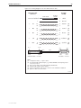
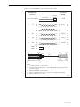
This Hardware Reference contains information on the following Port Interface
Cards (PICs):
■
AT-AR020 PRI E1/T1, a single ISDN Primary Rate E1/T1 interface
■
AT-AR021 (S) BRI- S/T, a single ISDN Basic Rate S/T interface
■
AT-AR021 (U) BRI-U, a single ISDN Basic Rate U interface
■
AT-AR022 ETH, a dual Ethernet 10BASE-T/AUI port
■
AT-AR023 SYN, a single 2Mbps synchronous interface
■
AT-AR024 ASYN4, four asynchronous ports
■
AT-AR026 4ETH, four Ethernet 10BASE-T ports
■
AT-AR027 VoIP-FXS, two Foreign Exchange Voice over IP ports
You can download the complete document set for PICs, and for your switch or
router, from www.alliedtelesis.com/support/software. For more information
about the document set and other resources, see “Obtaining Documentation
and Resources” on page 46.
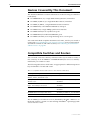
Compatible Switches and Routers
You can install a PIC into a PIC bay on the base unit of your switch or router, or
into a PIC bay on an AT-AR040 or AT-AR040-B NSM (Network Service Module)
installed in your switch or router.
The following table shows which PICs are appropriate for different expansion
bays and models of switch and router.
Table 1: Compatible switches and routers for Port Interface Cards (PICs)
This expansion bay ...
Accepts ...
PIC bays in the AR415S, AR440S, AR441S,
AR442S, AR725, and AR745 router
All PICs.
PIC bays in the AR750S, AR750S-DP, and
AR770S router
AT-AR020, AT-AR021, AT-AR023, and
AT-AR024.
AT-AR040 NSM in the AR745 router,
Rapier 16fi and Rapier 24i switch
All PICs except AT-AR022 and
AT-AR026.
AT-AR040-B NSM in the Rapier 24i-B switch
All PICs except AT-AR022 and
AT-AR026.
AT-AR040 NSM in the Rapier 48w switch
AT-AR020, AT-AR021v3, and AT-AR024.
AT-AR040-B NSM in the Rapier 48w-B switch
AT-AR020, AT-AR021v3, and AT-AR024.
The AT-AR021(S) V3 hardware revision, identified by the label “AR021v3” on
the board, requires a switch or router running AlliedWare® Operating System
version 2.9.1-13 or later.
C613-03023-00 REV P
Hardware Reference
5
Hardware Overview
This section provides an overview of the hardware features of PICs. PICs
provide a cost effective and flexible mechanism for adding new or additional
network interfaces to your switch or router. By adding or changing PICs,
network interface capabilities can be upgraded without replacing the switch or
router. A PIC can provide additional network interfaces, or can be replaced
with a different PIC to provide alternative interface types.
Hardware descriptions for your switch or router, Uplink Modules, and
Network Service Modules (NSMs) can be found in their respective Hardware
References. These documents can be downloaded from
www.alliedtelesis.com/support/software.
Common Features
The following hardware features are common to all PIC models.
Environmental
conditions
Regulatory
Standards
C613-03023-00 REV P
■
Operating temperature range: 0 ºC to 40 ºC (32 ºF to 104 ºF)
■
Storage temperature range: -25 ºC to 70 ºC (-13 ºF to 158 ºF)
■
Relative humidity range: 5% to 95% non-condensing
■
Emissions: EN55022 class A, FCC class A, and VCCI class A,
AS/NZS CISPR22
■
Immunity: EN55024
■
Safety: UL60950-1, CAN/CSA-C22.2 No. 60950-1-03, EN60950-1,
AS/NZS60950.1
6
Port Interface Card
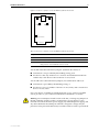
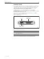
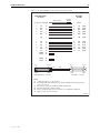
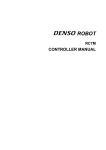
AT-AR020 PRI E1/T1 PIC
The AT-AR020 PRI E1/T1 PIC provides a single G.703/Primary Rate ISDN
WAN port with an RJ-45 connector.
The front panel of the AT-AR020 PRI E1/T1 PIC is shown in Figure 1, and the
functions of the LEDs are listed in Table 2.
Figure 1: AT-AR020 PRI E1/T1 PIC
D Data
B Data
PRI E1/T1
PRI E1/T1 (RJ45 connector)
LEDs
Active
NT
LEDs
AR020FP
Table 2: AT-AR020 PRI E1/T1 PIC LED functions
LED
Function
D Data
[ISDN mode only] Lit when HDLC packets are being exchanged between
the switch or router and the ISDN switch over the D (signalling) channel.
B Data
Lit when HDLC packets are being exchanged between the switch or
router and another end system device (normally another switch or router)
over any of the B (data) channels.
Active
Lit whenever operational (i.e., no RAI or AIS) frames are being received.
NT
[ISDN mode only] Lit when the PRI1 is operating in NT mode. This LED
should not be lit during normal operation.
The AT-AR020 supports both E1 and T1 operation. A jumper selects the
required mode. A second jumper selects NT (Network Terminator) or TE
(Terminal Equipment) mode, and the current mode is displayed by the NT LED.
This jumper is factory set to TE mode for normal operation and should not be
changed without contacting your ISDN service provider, or authorised Allied
Telesis distributor or reseller. Earlier versions of this card also have a J3 jumper.
If present, this jumper must be installed for E1 mode and removed for T1
mode.
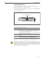
Jumper locations are shown in Figure 2 on page 7, and jumper functions are
listed in Table 3 on page 7.
C613-03023-00 REV P
Hardware Reference
7
RJ45
Active
NT
LED
LED
Figure 2: Location of jumpers on the AT-AR020 PRI E1/T1 PIC board
D Data
B Data
PRI
J2 (E1/T1)
S/N
J1 (NT/TE)
PIC CONNECTOR
AR020C
Table 3: Functions of jumpers on the AT-AR020 PRI E1/T1 PIC board
Jumper
Function
Default
J1
Selects ISDN NT mode (installed) or TE mode (not installed).
Not installed.
J2
Selects T1 mode (installed) or E1 mode (not installed).
Installed.
J3
Selects E1 mode (installed) or T1 mode (not installed).
Only present on earlier versions of the PIC.
-
Warning Do not attempt to install or remove the PIC, or change any jumpers on
the PIC, while the switch or router is connected to a power supply or a live
network. Disconnect the mains power supply, any redundant power supply, and
any cable attached to the WAN port of the PIC. Dangerous voltages may be
present on some parts of the PIC board, even if the switch or router is powered off.
C613-03023-00 REV P
8
Port Interface Card
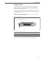
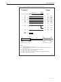
AT-AR021(S) BRI-S/T PIC
The AT-AR021(S) BRI-S/T PIC provides a single Basic Rate ISDN S/T WAN
port. The BRI port has an RJ-45 connector.
The front panel of the AT-AR021(S) PIC is shown in Figure 3 and the functions
of the LEDs are listed in Table 4.
Figure 3: AT-AR021(S) BRI-S/T PIC
B1
B2
BRI S/T
ISDN BRI S/T port (RJ45 connector)
LEDs
Active
D
LEDs
AR021SFP
Table 4: AT-AR021(S) BRI-S/T PIC LED functions
LED
Function
B1, B2
For on-demand ISDN, lit when there is a call up over the respective B
channel and flashing when data is being exchanged.
For permanent circuits, lit when HDLC packets are being exchanged
between the switch or router and another TE end system device (normally
another switch or router) over the respective B (data) channel.
Active
Lit when the BRI has successfully completed the exchange of INFO 1 and
INFO 2 signals, and INFO 3 and INFO 4 signals are present on the link. This
means that the ISDN interface is correctly connected to a working NT
device.
D
Lit when HDLC packets are being exchanged between the switch or
router and the ISDN switch over the D (signalling) channel.
In North America, the S/T interface must be supplied from a UL listed
network terminating device such as an NT1, and the cable length between the
AR021(S) PIC and the NT1 device must be less than 1000 metres.
Two user-configurable jumpers provide 100Ω line termination. Jumper
locations on the AT-AR021(S) V3 hardware revision are shown in Figure 4 on
page 9, and jumper functions are listed in Table 5 on page 9. The older V2
hardware revision of the AT-AR021(S) has the same jumpers and functions, but
the positions of the jumpers are reversed. The hardware revision is identified
by the label “AR021 V2” or “AR021v3” printed on the board.
The V3 hardware revision supports TE mode only. The V2 hardware revision
supports both TE and NT mode. Jumper J4, when installed, selects NT mode.
The PIC should be configured as a TE for normal operation.
C613-03023-00 REV P
Hardware Reference
9
LED
LED
Figure 4: Location of jumpers on the AT-AR021(S) BRI-S/T PIC board
RJ45
Active
D
B1
B2
BRI
J2
ISDN RX
TERMINATION
J1
ISDN TX
TERMINATION
J4
NT MODE (V2 REV ONLY)
PIC CONNECTOR
AR021SC
Table 5: Functions of jumpers on the AT-AR021(S) BRI-S/T PIC board
Jumper
Function
Default
J1
100Ω termination for TX.
Not installed.
J2
100Ω termination for RX.
Not installed.
J4
ISDN NT mode (installed) or TE mode (not installed).
Only present on V2 hardware revision of PIC.
Not installed.
You should install the termination jumpers (terminate Rx and Tx) if:
■
termination is not provided by the building wiring, and
■
the device is the only TE device on a Point-to-Point link between the NT
and the TE, or the device is the last device on an S/T bus
You should remove the termination jumpers (not terminate Rx and Tx) if:
■
termination is provided by the building wiring, or
■
the device is one of a number of devices on an S/T bus, and is not the last
device on an S/T bus
If you are unsure of whether to terminate the line or not, contact your ISDN
service provider or your authorised Allied Telesis distributor or reseller.
Warning Do not attempt to install or remove the PIC, or change any jumpers on
the PIC, while the switch or router is connected to a power supply or a live
network. Disconnect the mains power supply, any redundant power supply, and
any cable attached to the WAN port of the PIC. Dangerous voltages may be
present on some parts of the PIC board, even if the switch or router is powered off.
C613-03023-00 REV P
10
Port Interface Card
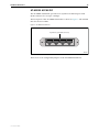
AT-AR021(U) BRI-U PIC
The AT-AR021(U) BRI-U PIC provides a single Basic Rate ISDN U Interface
WAN port. The BRI port has an RJ-45 connector.
The front panel of the AT-AR021(U) PIC is shown in Figure 5, and the functions
of the LEDs are listed in Table 6.
Figure 5: AT-AR021(U) BRI-U PIC
BRI U
ISDN BRI U interface (RJ45 connector)
B1
Active
B2
D
LEDs
AR021UFP
Table 6: AT-AR021(U) BRI-U PIC LED functions
LED
Function
B1, B2
Lit when HDLC packets are being exchanged between the switch or
router and another TE end system device (normally another switch or
router) over the respective B (data) channel.
For ISDN, lit when there is a call up over the respective B channel and
flashing when data is being exchanged.
Active
Lit when the U interface is in the Activated state (i.e., it is fully operational
at layer 1).
D
Lit when HDLC packets are being exchanged between the switch or
router and the ISDN switch over the D (signalling) channel.
There are no user-configurable jumpers on the AT-AR021(U) BRI-U PIC.
Warning Do not attempt to install or remove the PIC while the switch or router
is connected to a power supply or a live network. Disconnect the mains power
supply, any redundant power supply, and any cable attached to the WAN port
of the PIC. Dangerous voltages may be present on some parts of the PIC board,
even if the switch or router is powered off.
C613-03023-00 REV P
Hardware Reference
11
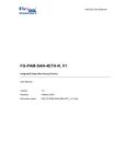
AT-AR022 ETH PIC
The AT-AR022 ETH PIC provides a dual Ethernet 10BASE-T/AUI port. Only
one interface type can be active at any one time and the PIC automatically
senses which interface is in use. The 10BASE-T interface uses an RJ-45
connector and the AUI interface uses a DB15 connector.
AT-AR022 ETH PICs are not recommended for use in AT-AR040 or
AT-AR040-B NSM PIC bays because performance of these interfaces is likely to
be reduced and packet loss may occur.
The front panel of the AT-AR022 ETH PIC is shown in Figure 6, and the
functions of the LEDs are listed in Table 7.
Figure 6: AT-AR022 ETH PIC
Ethernet AUI port
(DB15 connector)
Link
ETH
Data
LEDs
Ethernet 10BASET port
(RJ45 connector)
AR022FP
Table 7: AT-AR022 ETH PIC LED functions
LED
Function
Link
Lit when the Ethernet interface is connected to a device (e.g. a hub) which is
generating link pulses.
Data
Lit when data is being transmitted or received over the Ethernet interface.
There are no user-configurable jumpers on the AT-AR022 ETH PIC.
C613-03023-00 REV P
12
Port Interface Card
AT-AR023 SYN PIC
The AT-AR023 SYN PIC provides a single synchronous port operating at
speeds up to 2Mbps. The synchronous port has a 50-way AMPLIMITE
universal connector which supports RS-232/V.28, V.35 and X.21 interface
standards in DTE and DCE modes.
A transition cable is required to convert the AMPLIMITE connector to the
correct physical interface. The switch or router does not need to be rebooted to
change the interface type.
The front panel of the AT-AR023 SYN PIC is shown in Figure 7, and the
functions of the LEDs are listed in Table 8.
Figure 7: AT-AR023 SYN PIC
Synchronous port (AMPLIMITE 50-way connector)
Tx
SYN
Rx
LEDs
AR023FP
Table 8: AT-AR023 SYN PIC LED functions
LED
Function
Tx
Lit when data is being transmitted over the synchronous interface.
Rx
Lit when data is being received on the synchronous interface.
There are no user-configurable jumpers on the AT-AR023 SYN PIC.
C613-03023-00 REV P
Hardware Reference
13
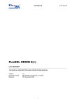
AT-AR024 ASYN4 PIC
The AT-AR024 ASYN4 PIC provides four asynchronous RS-232 ports with
RJ-45 connectors for use up to 115 Kbps.
The front panel of the AT-AR024 ASYN4 PIC is shown in Figure 8. The ASYN4
PIC does not have LEDs.
Figure 8: AT-AR024 ASYN4 PIC
Asynchronous ports (RJ45 connector)
0
ASYN
3
AR024FP
There are no user-configurable jumpers on the AT-AR024 ASYN4 PIC.
C613-03023-00 REV P
14
Port Interface Card
AT-AR026 4ETH PIC
The AT-AR026 4ETH PIC provides four 10BASE-T/100 BASE-TX autonegotiating ports. The ports have RJ-45 connectors and provide wire speed
unmanaged layer 2 switching.
AT-AR026 4ETH PICs are not recommended for use in AT-AR040 or
AT-AR040-B NSM PIC bays because performance of these interfaces is likely to
be reduced and packet loss may occur.
The front panel of the AT-AR026 4ETH PIC is shown in Figure 9, and the
functions of the LEDs are listed in Table 9 on page 14.
Figure 9: AT-AR026 4ETH PIC
10BASE-T/100BASE-TX Ethernet ports
(RJ45 connectors)
1
10/100 ETH
4
LEDs
AR026FP
Table 9: AT-AR026 4ETH PIC LED functions (two LEDs per port)
LED
Function
Left
Lit when the port is operating at 100Mbps and full duplex.
Right
Lit when a link has been established. Flashing when data is being transmitted
through the port.
The AT-AR026 PIC includes a switch chip that switches independently of the
switch, router, or NSM that the PIC is installed in. The show interface
command will show each correctly installed AT-AR026 as a single interface.
The 10/100 “front side” Ethernet ports will not be shown.
AT-AR026 features include:
■
Five integrated switch ports with physical layer transceivers—four 10/100
Ethernet switch ports, and one fixed 10 Mbps port acting as the PIC to base
unit connector
■
128 kbytes of frame buffering SRAM
■
1.4 Gbps high performance memory bandwidth
■
10BASE-T and 100BASE-TX modes of operation
■
LED indicators for link, activity, full/half duplex, and port speed
■
Hardware based 10/100, full/half duplex, flow control, and autonegotiation
C613-03023-00 REV P
Hardware Reference
15
■
Individual port forced full duplex and 100BASE-TX modes when autonegotiation is disabled
■
Wire speed reception and transmission
■
Integrated address look-up engine, supporting 1K absolute MAC
addresses
■
Automatic address learning, address aging, and address migration
■
Broadcast storm protection
■
Full duplex IEEE 802.3x flow control
■
Half duplex back pressure flow control
■
MDI/MDI-X auto cross over support
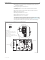
Some features, such as autonegotiation, buffer size, and MAC address aging,
are configured by adding or removing links on the PIC board. Figure 10 shows
the location of the configurable links on the board, and Table 10 on page 16 lists
the configurable features, their respective links, and their default settings.
Figure 10: Location of user configurable links on the AT-AR026 4ETH PIC
Link Detail
Configurable links
Link
1 2 3
Pads
Link Options
Up = 10kΩ link between pads 1 and 2
Down = 1kΩ link between pads 2 and 3
Floating = No links
All configurable links use 603 resistors
Links 22, 31, 40, and MRXD 3 are fixed and
cannot be configured
PIC connector
Ethernet ports
AR026C
C613-03023-00 REV P
16
Port Interface Card
Table 10: Configurable links on the AT-AR026 4ETH PIC
Function
Link
Up1
Down2
Floating3
Default
Flow control on all ports
13
Flow control
No flow control
N/A
Up
10BASE-T4, 100BASE-TX4,
or auto-negotiate on port 1
41
100BASE-TX
10BASE-T
Auto-negotiate
Floating
10BASE-T5, 100BASE-TX5,
or auto-negotiate on port 2
42
100BASE-TX
10BASE-T
Auto-negotiate
Floating
10BASE-T6, 100BASE-TX6,
or auto-negotiate on port 3
43
100BASE-TX
10BASE-T
Auto-negotiate
Floating
10BASE-T7, 100BASE-TX7,
or auto-negotiate on port 4
30
100BASE-TX
10BASE-T
Auto-negotiate
Floating
Full duplex4, half duplex4,
or auto-negotiate on port 1
50
Full duplex
Half duplex
Auto-negotiate
Floating
Full duplex5, half duplex5,
or auto-negotiate on port 2
51
Full duplex
Half duplex
Auto-negotiate
Floating
Full duplex6, half duplex6,
or auto-negotiate on port 3
52
Full duplex
Half duplex
Auto-negotiate
Floating
Full duplex7, half duplex7,
or auto-negotiate on port 4
53
Full duplex
Half duplex
Auto-negotiate
Floating
Back-off mode in half duplex
20
Aggressive
Standard
N/A
Up
Back pressure in half duplex
21
Enabled
Disabled
N/A
Up
MAC address ageing
23
Age out addresses
after 5 minutes
Don’t age out
addresses
N/A
Up
Limit on broadcast frames
32
25% of frames
No limit
N/A
Up
Drop packets after collisions
33
Don’t drop packets
Drop packets after
16 collisions
N/A
Down
Auto-negotiation on port 1
MCOL
Disable
Enable
N/A
Down
Auto-negotiation on port 2
MRXD 0
Disable
Enable
N/A
Down
Auto-negotiation on port 3
MRXD 1
Disable
Enable
N/A
Down
Auto-negotiation on port 4
MRXD 2
Disable
Enable
N/A
Down
205 buffers per port (max)
10 & 11
NA
1k (link 10),
1k (link 11)
N/A
N/A
512 buffers per port (max)
10 & 11
10k (link 11)
1k (link 10)
N/A
N/A
768 buffers per port (max)
10 & 11
10k (link 10)
1k (link11)
N/A
N/A
512 buffers per port
(adaptive)
10 & 11
10k (link 10),
10k (link 11)
NA
N/A
Up (link 10)
Up (link 11)
1.
2.
3.
4.
5.
6.
7.
Up = 10kΩ link between pads 1 and 2.
Down = 1kΩ link between pads 2 and 3
Floating = no link.
Requires auto-negotiation on port 1 to be disabled using link MCOL.
Requires auto-negotiation on port 2 to be disabled using link MRXD 0.
Requires auto-negotiation on port 3 to be disabled using link MRXD 1.
Requires auto-negotiation on port 4 to be disabled using link MRXD 2.
Caution Links 22, 31, 40, and MRXD 3 are fixed and should not be changed.
Changing these links will cause the PIC to cease functioning.
The AT-AR026 PIC does not support the AlliedWare operating system’s
diagnostic or Test Facility features.
C613-03023-00 REV P
Hardware Reference
17
AT-AR027 VoIP-FXS PIC
The AT-AR027 VoIP-FXS PIC provides two Foreign Exchange Subscriber (FXS)
ports. The ports use RJ-11 connectors and can be connected to standard analog
telephony equipment such as telephones, fax machines and modems. The FXS
interface supplies ring, voltage and dial tone.
The front panel of the AT-AR027 VoIP-FXS PIC is shown in Figure 11, and
functions of the LEDs are listed in Table 11 on page 17.
Figure 11: AT-AR027 VoIP-FXS PIC
FXS
Two FXS VoIP Ports
(RJ-11 connectors)
OFF HOOK
/RING
PIC REG
1
0
OFF HOOK
/RING
PIC ERROR
Four LEDs
AR027FP
Table 11: AT-AR027 VoIP-FXS PIC LED functions
LED
State
Function
Off Hook/Ring
Off
The port is on-hook.
Green
The port is off-hook.
Flashing
An incoming call is present on the port.
Off
The PIC is not registered with a gatekeeper and external
phone calls cannot be made.
Flashing
The PIC is registered with a gatekeeper or gatekeeper has
been set to “None”. External calls can only be made if the
PIC is registered with a gatekeeper.
Off
The PIC is okay.
Green
An internal error has occurred. Reset the PIC using the
reset voip command.
PIC Reg
PIC Error
AT-AR027 features include:
C613-03023-00 REV P
■
Settable ring wave form
■
Settable tone generation
■
Settable port gain/attenuation for transmit and receive on each port
■
600r, 600c, 900c, Cplx and Cplx2 port impedance.
■
Frame buffer management
18
Port Interface Card
■
Voice activation and silence detection
■
Compatible with H.233, Session Initiation Protocol (SIP) and Media
Gateway Control Protocol (MGCP)
You can install a maximum of four AT-AR027 PICs in an AR745 router fitted
with an AT-AR040 NSM.
For more information on VoIP protocols and how to configure them, see the
Voice Over IP (VoIP) chapter of the AlliedWare® Operating System Software
Reference for your switch or router. You can download this document from
www.alliedtelesis.com/support/software.
C613-03023-00 REV P
Hardware Reference
19
PIC Interfaces
This section provides detailed information on the physical and operational
characteristics of the following PIC interfaces:
■
Asynchronous Interface
■
Synchronous Interface
■
Ethernet Interface
■
Basic Rate ISDN Interface
■
Primary Rate ISDN Interface
■
VoIP FXS Interface
Asynchronous Interface
The AT-AR024 ASYN4 PIC provides four RS-232 asynchronous interfaces
using RJ-45 connectors. Table 12 shows the pinout of the asynchronous
interfaces.
Table 12: Pinout of the RJ-45 connectors on the AT-AR024 ASYN4 PIC
Pin*
Function
Signal Direction
1
RING
Input to PIC
2
DCD
Input to PIC
3
DTR
Output from PIC
4
GND
5
RXD
Input to PIC
6
TXD
Output from PIC
7
CTS
Input to PIC
8
RTS
Output from PIC
*Pins are numbered from left to right.
A range of speeds are selectable using the set asyn command. For more
information, see the Interfaces chapter of the AlliedWare® Operating System
Software Reference for your switch or router.
Not all signals need to be connected. In particular, DCD and CTS are not
required unless the interface has been specifically set up to use them. For more
information, see the Line Printer Daemon (LPD) and Stream Printing chapters of
the AlliedWare® Operating System Software Reference for your switch or router. A
typical terminal connection will only require RXD, TXD and GND, but refer to
the equipment manual for the connected device for more specific data.
If LPD-based printer ports are required, then the switch or router may expect to
see the DTR signal from the printer connected to the DCD pin of the switch.
This is used to detect that the printer is powered on and online. This prevents
print jobs being sent to a disconnected printer and lost. For more information,
see the Line Printer Daemon (LPD) chapter of the AlliedWare® Operating System
Software Reference for your switch or router.
C613-03023-00 REV P
20
Port Interface Card
Synchronous Interface
The AT-AR023 SYN PIC provides a synchronous interface with a single
AMPLIMITE 50-way port. The AMPLIMITE port is wired as a universal
connector for RS-232/V.28, V.35 and X.21 interface standards in both DTE and
DCE modes. A transition cable is required to convert the AMPLIMITE to the
correct physical interface for the standard required (e.g., DB15 for X.21). The
transition cable can be ordered from your supplier, or you can construct your
own cable.
The transition cable does more than simply change the physical connector. The
interface hardware reads the cable type from the AMPLIMITE plug and
enables or disables the internal driver electronics as required. To function
correctly, the cables must be identical to the cables described in “Cables and
Loopback Plugs for PICs” on page 23.
The DCE cable type reverses the direction of the data lines as well as the clock
lines. This cable is intended to be used when the switch or router supplies the
clock for the attached device. This is commonly used when the switch or router
is connected to the synchronous interface of another device or a host, without
using an intermediate modem or NTU (Network Terminating Unit). Therefore,
the DCE cable must only be connected to a switch or router interface that is set
to generate the clock. For more information, see the Interfaces chapter of the
AlliedWare® Operating System Software Reference for your switch or router.
The transition cable can be changed at any time. It is not necessary to powerdown the switch or router.
When an RS-232 DCE transition cable is connected to a synchronous interface
configured to generate clocks, the maximum clock speed is 38400 bps. When an
X.21 DCE or V.35 DCE transition cable is connected to a synchronous interface
configured to generate clocks, the maximum clock speed is 2 Mbps.
Ethernet Interface
The AT-AR022 ETH PIC has a dual 10BASE-T/AUI Ethernet interface. Only
one Ethernet interface type can be active at any one time. The PIC auto-senses
which Ethernet interface type is in use.
The AT-AR026 4ETH PIC has four 10BASE-T/100BASE-TX ports with RJ-45
connectors. Port characteristics such as speed, flow control, half/full duplex,
and auto-negotiation can be set by configuring links on the PIC’s PCB. See
“AT-AR026 4ETH PIC” on page 14 for more information.
For performance reasons, the AT-AR022 and AT-AR026 PICs should not be
installed in the AT-AR040 or AT-AR040-B NSM.
Basic Rate ISDN Interface
The AT-AR021(S) BRI-S/T and AT-AR021(U) PICs provide Basic Rate ISDN
(BRI) interfaces. In both cases the connecter type is RJ-45. The interfaces
support two 64K B channels and one D channel. Table 13 on page 21 shows the
pinout of the BRI interface.
C613-03023-00 REV P
Hardware Reference
21
Table 13: Pinout of the Basic Rate ISDN interface
Pin
S/T Interface Functions
U Interface Functions
1
-
-
2
-
-
3
TX+
-
4
RX+
positive (+)
5
RX-
negative (-)
6
TX-
-
7
-
-
8
-
-
The V2 hardware revision of the AT-AR021(S) PIC supports both TE and NT
operational modes. A jumper is used to select the operational mode. See
“AT-AR021(S) BRI-S/T PIC” on page 8 for more information. The V3 hardware
revision of the AT-AR021(S) PIC and the AT-AR021(U) PIC support TE mode
only. The hardware revision is identified by the label “AR021 V2” or
“AR021v3” printed on the board. The Integrated Services Digital Network (ISDN)
chapter of the AlliedWare® Operating System Software Reference for your switch
or router has detailed descriptions of the two operational modes. Your switch
or router should be configured as a TE for normal operation.
The AT-AR021(S) PIC can be configured using jumpers to provide 100Ω line
termination. See “AT-AR021(S) BRI-S/T PIC” on page 8 for more information.
Primary Rate ISDN Interface
The AT-AR020 PRI E1/T1 PIC provides a Primary Rate ISDN interface with a
single RJ-45 connector. The interface supports connection to either 100Ω T1 or
120Ω E1 networks. Table 3 on page 7 lists the jumper settings for E1 and T1
networks. Table 14 shows the pinout of the PRI interface.
Table 14: Connection standard for Primary Rate ISDN RJ-45 connectors
Pin*
Signal
1
RX+
2
RX-
3
RX ground selection from jumper
4
TX+
5
TX-
6
TX ground selection from jumper
7
Not connected
8
Not connected
*Pins are numbered from left to right, with latch down, as viewed from the rear.
C613-03023-00 REV P
22
Port Interface Card
VoIP FXS Interface
The AT-AR027 VoIP-FXS PIC uses standard RJ-11 telephone sockets that
provide a Tip and Ring A/B pair (Table 15). An RJ-11 to BT adaptor cable can
be used to connect telephones with BT-style plugs to the RJ-11 ports (Figure 20
on page 32).
Table 15: Pinout of the voice port RJ-11 connectors
Pin
Function
1
Not connected
2
Not connected
3
RING
4
TIP
5
SHUNT
6
Not connected
C613-03023-00 REV P
Hardware Reference
23
Cables and Loopback Plugs for PICs
This section describes how to make cables for connecting PIC interfaces to
other devices, and loopback plugs for testing PIC interfaces.
The following topics are covered:
■
Transition Cables for the AT-AR023 PIC
■
ISDN Interface Cables
■
BT Adaptor Cable for the AT-AR027 PIC
■
Terminal and Modem Cables
■
Ethernet Transceivers and AUI Cables
■
Loopback Plugs for Testing Interfaces
Transition Cables for the AT-AR023 PIC
The synchronous port on the AT-AR023 SYN PIC uses an AMPLIMITE 50-way
connector wired as a universal connector to support RS-232/V.28, V.35 and
X.21 interface standards in DTE and DCE modes.
A transition cable is required to convert the AMPLIMITE to the correct
physical interface for the standard required (e.g. DB15 for X.21). The transition
cable can be ordered from your distributor or reseller, or you can construct
your own cable by following the wiring diagrams in this section.
The transition cable does more than simply change the physical connector. The
switch or router hardware ‘reads’ the cable type from the AMPLIMITE plug
and enables or disables the internal driver electronics as required. To function
correctly, the cables must be identical to the cables described in this section.
The DCE cable type reverses the direction of the data lines as well as the clock
lines. This cable is intended to be used when the switch or router supplies the
clock for an attached device. This is commonly used when the switch or router
is connected to the synchronous port of another switch, router, or host, without
using an intermediate modem or NTU (Network Terminating Unit). Therefore,
the DCE cable must only be connected to a port which is set to generate the
clock. The Interfaces chapter of the AlliedWare® Operating System Software
Reference for your switch or router has more information. The AMPLIMITE
connector supports both DTE and DCE modes for all three physical standards.
The switch or router interface is fully compliant with V.35 but many DCE
(DSU/CSU) devices are not. Therefore, pay particular attention to V.35
connections. Because of the low signal levels used for V.35 (500mV point-topoint), issues such as ground loops and excess cable length become more
important than with X.21. In particular, some DCE devices connect the cable
ground to chassis or safety ground. This can create an earth loop condition
through the shield wire of the V.35 interface. The symptom of this condition is
unexpectedly high received packet errors (CRC, Abort etc.) as seen in the
output of the show syn counters command. In these cases the suggested
remedy is to break the earth loop by disconnecting (and isolating) pin A inside
the M34 connector. This action does not compromise the safety of the product
in any way.
The transition cable can be changed at any time. It is not necessary to powerdown the switch or router.
C613-03023-00 REV P
24
Port Interface Card
Good quality, data-grade cables should be used for all cables. Transition cables
must be made from paired cable with an overall foil shield. Metalised
backshells must also be used. Poor quality cables limit the maximum speed or
the maximum length of the cable, or both.
It is very important that cables do not degrade the EMC emission standards of
the switch, router, or PIC (e.g., FCC, CISPR). The cable foil shield must be
connected to the AMPLIMITE metalised backshell with a 360 degree ferrule. In
addition, on specified cables, a clip-on cable ferrite must be attached to the
cable at the AMPLIMITE end, no more than 25 mm from the rear of the
backshell of the AMPLIMITE connector. Contact your authorised Allied Telesis
distributor or reseller for a list of approved ferrites.
Use the following pin wiring diagrams when constructing transition cables for
each physical interface standard.
For this physical interface type ...
Follow this pin wiring diagram ...
RS-232 DTE
Figure 12 on page 25
RS-232 DCE
Figure 13 on page 26
V.35 DTE
Figure 14 on page 27
V.35 DCE
Figure 15 on page 28
X.21 DTE
Figure 16 on page 29
X.21 DCE
Figure 17 on page 30
C613-03023-00 REV P
Hardware Reference
25
Figure 12: Pin wiring diagram for an RS-232 DTE transition cable
D50 SCSI-2 Male
(to device)
D25 Male
(to DCE)
Connect to backshell
→
←
→
←
←
←
←
←
→
→
→
Pin 1
Cable Shield
1
Shield
TD
RD
RTS
CTS
DSR
12
2
14
3
4
2
3
4
5
6
TD
RD
RTS
CTS
DSR
(103)
(104)
(105)
(106)
(107)
SG
1
7
SG
(102)
CD
TC
RC
LL
DTR
RL
FGND
FSELA
5
10
8
16
13
15
21
22
8
15
17
18
20
21
CD
TC
RC
LL
DTR
RL
(109)
(114)
(115)
(141)
(108)
(140)
FGND
FSELB
46
47
Pin 25
Pin 1
Ferrite
Pin 26
Insulating
Sheath
Pin 50
D50 SCSI-2 Male — Pin View
Pin 13
Cable
Pin 14
Pin 25
D25 Male — Pin View
Notes:
(1) → Output from device; ← Input to device.
(2) Use shielded cable with twisted pairs, e.g. UL2789 28AWG. Twisted pairing must be
1-26, 2-27, 3-28, etc.
(3) D25 connector shells to be metallised and fully shielded 360°.
(4) Standard cable length is 2.05m ± 0.05m.
(5) Ferrite to be fitted to cable 31mm ± 3mm from rear of D50 SCSI-2 backshell.
(6) Applies to cable version 4.0 or later.
A50R232T
C613-03023-00 REV P
26
Port Interface Card
Figure 13: Pin wiring diagram for an RS-232 DCE transition cable
D50 SCSI-2 Male
(to device)
D25 Female
(to DTE)
Connect to backshell
←
→
←
→
→
Cable Shield
Insulating
Sheath
1
Shield
→
RD
TD
CTS
RTS
DTR
SG
RL
2
12
3
14
13
1
15
2
3
4
5
6
7
8
TD
RD
RTS
CTS
DSR
SG
CD
(103)
(104)
(105)
(106)
(107)
(102)
(109)
→
TCG
20
15
TC
(114)
17
RC
(115)
20
DTR
(108)
←
Pin 1
DSR
4
FGND
FSELA
21
22
Pin 13
Pin 25
Ferrite
Pin 26
Pin 50
D50 SCSI-2 Male — Pin View
Pin 1
Cable
Pin 25
Pin 14
D25 Female — Pin View
Notes:
(1) → Output from device; ← Input to device.
(2) Use shielded cable with twisted pairs, e.g. UL2789 28AWG. Twisted pairing must be
1-26, 2-27, 3-28, etc.
(3) D25 connector shells to be metallised and fully shielded 360°.
(4) Standard cable length is 2.05m ± 0.05m.
(5) Ferrite must be fitted to cable 31mm ± 3mm from rear of D50 SCSI-2 backshell.
(6) Applies to cable version 4.0 or later.
A50R232C
C613-03023-00 REV P
Hardware Reference
27
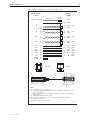
Figure 14: Pin wiring diagram for a V.35 DTE transition cable
D50 SCSI-2 Male
(to device)
M34 Male
(to DCE)
Connect to backshell
Insulating
Sheath
Cable Shield
A
Shield
B
SIG G
A
P
S
SDA
SDB
(103)
1
→
TD
←
TC
10
35
B
Y
AA
TCA
TCB
(114)
←
RD
2
27
B
R
T
RDA
RDB
(104)
←
RC
8
33
B
V
X
RCA
RCB
(115)
→
←
←
→
←
→
→
RTS
CTS
CD
DTR
DSR
LL
RL
FGND
FSELB
14
3
5
13
4
16
15
46
47
C
D
F
H
E
L
N
RTS
CTS
DCD
DTR
DSR
LL
RL
(105)
(106)
(109)
(108)
(107)
(141)
(140)
12
37
(−5V) 25
200R
180R
105R
180R
Network A
Network B
300R
300R
200R
Pin 1
Pin A
Pin 25
Ferrite
Pin 26
Pin 50
D50 SCSI-2 Male — Pin View
Pin C Pin KK
Pin MM
Cable
Pin B
Pin D Pin LL
Pin NN
M34 Male — Pin View
Notes:
(1) → Output from device; ← Input to device.
(2) Use shielded cable with twisted pairs, e.g. UL2919 28AWG. Twisted pairing must be
1-26, 2-27, 3-28, etc.
(3) M34 connector shells must be metallised. Connect braid to connector shells to make a
360° connection.
(4) Standard cable length is 2.05m ± 0.05m.
(5) Ferrite must be fitted to cable 31mm ± 3mm from rear of D50 SCSI-2 backshell.
(6) Resistors are 1% tolerance.
(7) Applies to cable version 2.0 or later.
A50V35T
C613-03023-00 REV P
28
Port Interface Card
Figure 15: Pin wiring diagram for a V.35 DCE transition cable
D50 SCSI-2 Male
(to device)
M34 Female
(to DTE)
Connect to backshell
Insulating
Sheath
Cable Shield
A
Shield
1
B
SIG G
←
TD
12
37
R
T
RDA
RDB
(104)
→
TC
20
45
Y
AA
TCA
TCB
(114)
→
RD
2
27
P
S
SDA
SDB
(103)
V
X
RCA
RCB
(115)
C
H
D
E
F
RTS
DTR
CTS
DSR
DCD
(105)
(108)
(106)
(107)
(109)
←
←
→
→
→
Pin 1
CTS
DSR
RTS
DTR
RL
FGND
FSELB
FGND
FSELC
3
4
14
13
15
46
47
21
23
Pin MM
Pin 25
Ferrite
Pin 26
Pin 50
D50 SCSI-2 Male — Pin View
Pin KK Pin C
Pin A
Cable
Pin NN
Pin LL Pin D
Pin B
M34 Female — Pin View
Notes:
(1) → Output from device; ← Input to device.
(2) Use shielded cable with twisted pairs, e.g. UL2919 28AWG. Twisted pairing must be
1-26, 2-27, 3-28, etc.
(3) M34 connector shells must be metallised. Connect braid to connector shells to make a
360° connection.
(4) Standard cable length is 2.05m ± 0.05m.
(5) Ferrite must be fitted to cable 31mm ± 3mm from rear of D50 SCSI-2 backshell.
(6) Applies to cable version 2.0 or later.
A50V35C
C613-03023-00 REV P
Hardware Reference
29
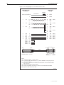
Figure 16: Pin wiring diagram for an X.21 DTE transition cable
D50 SCSI-2 Male
(to device)
D15 Male
(to DCE)
Connect to backshell
Insulating
Sheath
Cable Shield
1
Shield
1
8
Ground
→
TD
12
37
2
9
Transmit
(A)
(B)
→
RTS
14
39
3
10
Control
(A)
(B)
←
RD
2
27
4
11
Receive
(A)
(B)
←
CD
5
30
5 Indication
12
(A)
(B)
←
RXC
8
33
6
13
(A)
(B)
Pin 1
Pin 25
Pin 1
Ferrite
Pin 26
Pin 50
D50 SCSI-2 Male — Pin View
S (Clock)
Pin 8
Cable
Pin 9
Pin 15
D15 Male — Pin View
Notes:
(1) → Output from device; ← Input to device.
(2) Use shielded cable with twisted pairs, e.g. UL2789 28AWG. Twisted pairing must be
1-26, 2-27, 3-28, etc.
(3) D15 connector shells to be metallised and fully shielded 360°.
(4) Standard cable length is 2.05m ± 0.05m.
(5) Ferrite must be fitted to cable 31mm ± 3mm from rear of D50 SCSI-2 backshell.
(6) Applies to cable version 3.0 or later.
A50X21T
C613-03023-00 REV P
30
Port Interface Card
Figure 17: Pin wiring diagram for an X.21 DCE transition cable
D50 SCSI-2 Male
(to device)
D15 Female
(to DTE)
Connect to backshell
Insulating
Sheath
Cable Shield
1
Shield
1
8
Ground
Receive
←
TD
12
37
4
11
←
RTS
14
39
5 Indication
12
(A)
(B)
→
RD
2
27
2
9
Transmit
(A)
(B)
→
CD
5
30
3
10
Control
(A)
(B)
→
TXC
20
45
6
13
S (Clock)
(A)
(B)
FGND
FSELC
21
23
Pin 1
Pin 25
Pin 8
Ferrite
Pin 26
Pin 50
D50 SCSI-2 Male — Pin View
(A)
(B)
Pin 1
Cable
Pin 9
Pin 15
D15 Female — Pin View
Notes:
(1) → Output from device; ← Input to device.
(2) Use shielded cable with twisted pairs, e.g. UL2789 28AWG. Twisted pairing must be
1-26, 2-27, 3-28, etc.
(3)
(4)
(5)
(6)
D15 connector shells to be metallised and fully shielded 360°.
Standard cable length is 2.05m ± 0.05m.
Ferrite must be fitted to cable 31mm ± 3mm from rear of D50 SCSI-2 backshell.
Applies to cable version 1.1 or later.
A50X21C
C613-03023-00 REV P
Hardware Reference
31
ISDN Interface Cables
The AT-AR021(S) BRI-S/T and AT-AR021(U) BRI-U PICs provide Basic Rate
ISDN interfaces, while the AT-AR020 PRI E1/T1 provides a Primary Rate ISDN
interface.
ISDN Basic Rate
Cable
Figure 18 shows how to wire a cable to connect a Basic Rate Interface (BRI) to
the ISDN network terminating equipment (NT).
Figure 18: Pin wiring diagram for an ISDN Basic Rate straight-through interface cable
RJ45
(to switch or router)
Not
Not
→
→
←
←
Not
Not
connected
connected
TX+
TXRXRX+
connected
connected
Notes:
(1)
(2)
(3)
(4)
1
2
3
6
4
5
7
8
RJ45
(to NT)
1
2
3
6
4
5
7
8
Not connected
Not connected
RX+
→
RX→
TX←
TX+
←
Not connected
Not connected
→ Output from switch or router; ← Input to switch or router.
Use twisted pair cable, with pairs 3 and 6, and 4 and 5.
Each wire is connected to the same pins at each end.
Cable version 1.0.
BRI1NT
ISDN Primary Rate
Cable
Figure 19 shows how to wire a cable to connect to the RJ-45 connector of a
Primary Rate Interface (PRI). Currently there is no accepted standard for the
connector at the network termination end, so only the switch end of the cable is
shown. Consult you ISDN service provider for more information.
Figure 19: Pin wiring diagram for an ISDN Primary Rate interface (120Ω) cable
RJ45
(to switch or
router)
←
RX+
←
RXNot connected
→
TX+
→
TXNot connected
Not connected
Not connected
Notes:
(1)
(2)
(3)
1
2
3
4
5
6
7
8
→ Output from switch or router; ← Input to switch or router.
Use Grade 5 twisted pair cable, with pairs 1 and 2, and 4 and 5.
Cable version 1.0.
PRI120NT
C613-03023-00 REV P
32
Port Interface Card
BT Adaptor Cable for the AT-AR027 PIC
The AT-AR027 VoIP-FXS PIC uses a standard RJ-11 connector. To connect
telephones with a BT-style connector, use an RJ-11 to BT adaptor cable
(Figure 20).
Figure 20: Pin wiring diagram for an RJ-11 to BT adaptor cable
RJ11 Plug
BT Socket
3
4
5
Pin 1
5
2
3
Pin 6
Cable
RJ11 — Router end view
Pin 6
Pin 1
BT Socket — Pin view
Notes:
(1) The SHUNT line (RJ11 pin 5/BT jack pin 3) is only required by some phones. If not
connected they will not ring.
RJ11BT
Terminal and Modem Cables
The following terminal and modem cables are described in this section:
■
RJ-45 terminal cable
■
Modem cable
■
Macintosh serial cable
An alternative method, for both terminal and modem cables, is to wire an RJ-45
patch cord (a straight pin-to-pin cable with RJ-45 connectors on both ends) and
then use an RJ-45-to-DB25 adaptor wired internally as a crossed cable. These
adaptors are available in both DB25 female and male versions from data
cabling suppliers, and are supplied with wires terminated on the RJ-45 socket
and pins on the free ends. The pins are inserted into the appropriate positions
in the DB25 shell.
C613-03023-00 REV P
Hardware Reference
RJ-45 terminal
cable
33
Figure 21 shows how to wire a cable to connect a standard VT100-compatible
terminal to an asynchronous (RJ-45) port. Some terminals are fitted with a
DB25 female connector rather than a DB25 male connector. In this case the
cable should be fitted with a DB25 male connector.
Figure 21: Pin wiring diagram for a standard RJ-45 terminal cable
RJ45
(to switch or router)
←
→
←
→
(RXD)
(TXD)
(CTS)
(RTS)
5
6
7
8
→
←
←
←
(GND)
(DTR)
(DCD)
(RING)
4
3
2
1
Notes:
(1)
(2)
(3)
DB25 Female
(to terminal)
1 Not connected
2
3
4
5
6 Not connected
7
8
20
22
Other pins are not connected.
→ Output from switch or router; ← Input to switch or router.
Cable version 1.0.
TERMINAL
Modem cable
Figure 22 shows how to wire a cable to connect an asynchronous (RJ-45) port to
a modem.
Figure 22: Pin wiring diagram for a standard modem cable
RJ45
(to switch or router)
→
←
→
←
(TXD)
(RXD)
(RTS)
(CTS)
6
5
8
7
←
←
→
←
(GND)
(DCD)
(DTR)
(RING)
4
2
3
1
Notes:
(1)
(2)
(3)
DB25 Male
(to modem)
1 Not connected
2
3
4
5
6 Not connected
7
8
20
22
Other pins are not connected.
→ Output from switch or router; ← Input to switch or router.
Cable version 1.0.
MODEM
C613-03023-00 REV P
34
Port Interface Card
Macintosh serial
cable
Figure 23 shows how to wire a cable to connect an asynchronous (RJ-45) port
on the router or switch to the COM port on a Macintosh.
Figure 23: Pin wiring diagram for a Macintosh serial cable
RJ45
(to switch or router)
←
→
←
→
→
←
→
(DCD)
(RTS)
(RXD)
(GND)
(TXD)
(CTS)
(DTR)
Notes:
(1)
(2)
1
2
8
5
4
6
7
3
MiniDin
(to Macintosh)
1
2
3
4
5
6 Not connected
7
8
→ Output from switch or router; ← Input to switch or router.
Cable version 1.0.
MINIDIN
Ethernet Transceivers and AUI Cables
There are four types of Ethernet transceiver available (Table 16). The 10BASE-5
thick Ethernet transceiver will be remote from the router, due to the nature of
the coaxial cable, and will therefore require an AUI cable. The other types of
transceiver may be connected using an AUI cable or, if the transceiver is small
and lightweight, it may be connected directly to the AUI port on the back of the
PIC. Care must be taken to avoid strain on the AUI port connector.
Table 16: Ethernet transceivers, media, and connector types
Transceiver Type
Media
Connector
10BASE-2
Thin Ethernet coaxial cable
BNC
10BASE-T
Twisted pair (category 3 or better)
RJ-45
10BASE-F
Fibre optic (dual)
ST or SMA
10BASE-5
Thick Ethernet coaxial cable
Vampire TAP or “N” type
The router may also be connected to a network via an AUI fanout. This device
has multiple AUI ports wired as transceiver AUIs and a single standard AUI
for connection of a transceiver. This allows several Ethernet devices to share a
single transceiver. An AUI cable is required if this method is used.
Transceivers have a switch or a jumper to enable or disable SQE (Signal Quality
Error, also known as heartbeat). The router does not require SQE, so it should
be disabled.
AUI cables, sometimes known as drop or transceiver cables, are available from
data cabling suppliers in a variety of lengths up to a maximum of 40 metres,
but are typically one to five metres in length. AUI cables always have one
female and one male DB15 connector and are fitted with slide lock retaining
clips to ensure a secure attachment.
C613-03023-00 REV P
Hardware Reference
35
Loopback Plugs for Testing Interfaces
Loopback plugs are used in conjunction with the Test Facility in the
AlliedWare operating system to test the physical interfaces on all PICs except
the AT-AR026 and AT-AR027. For more information about the Test Facility, see
“Test Facility” on page 43, and the Test Facility chapter of the AlliedWare®
Operating System Software Reference.
A loopback plug connects the output pins on the interface to the input pins so
that any data transmitted over the interface is looped back (hence loopback
plug) and received at the same interface.
On interfaces with control signals, these are also looped back. The data
received on the interface is compared with the data transmitted on the interface
to determine whether or not the interface is functioning correctly. In order to
produce a comprehensive test report for the interface being tested, most tests
performed by the Test Facility require a loopback plug to be inserted.
Synchronous interfaces require an external test device to be used in conjunction
with the Test Facility. Use a loopback test to the local DCE.
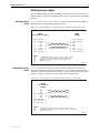
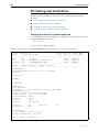
BRI S/T interfaces that use an MC145574 transceiver require a loopback plug to
test the BRI interface. To determine which type of transceiver a BRI interface
uses, use the command:
show bri test
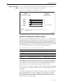
Figure 24 shows an example of the output screen from the show bri test
command. The transceiver type is listed in the first line of output.
Figure 24: Example output from the show bri test command
Test switches for BRI instance 0 (MC145574 transceiver):
Number
Action
Status
-----------------------------------------------------1
Transceiver B1 GCI Transp Loop ........... no
2
Transceiver B2 GCI Transp Loop ........... no
3
Transceiver 2B+D GCI Transp Loop ......... no
4
Transceiver B1 GCI Non-Transp Loop ....... no
5
Transceiver B2 GCI Non-Transp Loop ....... no
6
Transceiver B1 S/T Transp Loop ........... no
7
Transceiver B2 S/T Transp Loop ........... no
8
Transceiver B1 S/T Non-Transp Loop ....... no
9
Transceiver B2 S/T Non-Transp Loop ....... no
10
Transceiver External S/T Loop ............ no
11
Transceiver 96kHz Test Tone .............. no
12
Transceiver Force Activation ...... ...... no
13
Transceiver Ignore D Channel Procs ....... no
14
Transceiver Map E Channel to GCI ......... no
15
Transceiver GCI Free Run ................. no
BRI S/T interfaces that do not use an MC145574 transceiver, and BRI U
interfaces, do not require loopback plugs. The Test Facility will perform an
internal loopback test on these interfaces. To perform an external loopback test,
an external NT mode device is required. To test NT mode operation on the V2
hardware revision of the AR021(S) PIC, use an external TE device.
C613-03023-00 REV P
36
Port Interface Card
Use the following pin wiring diagrams when constructing loopback plugs for
each PIC interface type.
For this physical interface type ...
Follow this pin wiring diagram ...
RJ-45 asynchronous
Figure 25
Ethernet AUI
Figure 26
Ethernet TP
Figure 27 on page 37
ISDN Primary Rate
Figure 28 on page 37
ISDN Basic Rate S/T, depending on transceiver
Figure 29 on page 37
ISDN Basic Rate U
No loopback plug required
Figure 25: RJ-45 loopback plug for testing asynchronous interfaces
RJ45 Asynchronous Port Loopback Plug (RJ45 connector)
8 7 6 5 4 3 2 1
(RING)
(DCD)
(DTR)
(GND)
(RXD)
(TXD)
(CTS)
(RTS)
1
2
3
4
5
6
7
8
End view
of plug
RJ45LOOP
Figure 26: Ethernet AUI loopback plug
AUI Loopback Plug (Female D15 connector)
1
2
3
4
5
6
7
8
9
10
11
12
13
14
15
C1 = 100nF ceramic capacitor
C2 = 100nF ceramic capacitor
R1 = 1K resistor
C1
C2
R1
LED
Note
The LED and resistor provide
optional power feed checking.
They are not required for
loopback testing.
AUILOOP
C613-03023-00 REV P
Hardware Reference
37
Figure 27: Ethernet twisted pair (TP) loopback plug
Twisted Pair (TP) Loopback Plug (RJ45 connector)
8 7 6 5 4 3 2 1
TX+
TXRX+
RX-
1
2
3
4
5
6
7
8
End view
of plug
Not
connected
Not
connected
•Not
TPLOOP
Figure 28: Primary Rate ISDN loopback plug
PRI Loopback Plug (RJ45 connector)
8 7 6 5 4 3 2 1
TX+
TXRX+
RX-
1
2
3
4
5
6
7
8
Switch or router
end view
P120LOOP
Figure 29: Basic Rate ISDN loopback plug wiring diagram
BRI Loopback Plug (RJ45 connector)
8 7 6 5 4 3 2 1
TX+
RX+
RXTX-
1
2
3
4
5
6
7
8
Not connected
Not connected
Router end view
of plug
Not connected
Not connected
BRILOOP
C613-03023-00 REV P
38
Port Interface Card
Hot Swapping the AT-AR040 or
AT-AR040-B NSM with PICs Installed
Caution You cannot hot swap PICs. Before installing or removing a PIC from a
PIC bay in a switch or router, you must disconnect all power sources to the
switch or router. To install or remove a PIC from an AR040 or AR040-B NSM,
you must first either physically remove the NSM from the switch or router
using the hot swap method, or disconnect all power sources to the switch or
router.
Hot swapping is the installation or removal of a component such as an NSM
without powering down or restarting the switch or router. You can hot swap
the AT-AR040 or AT-AR040-B NSM on a switch or router running Software
Version 2.3.1 or later. To find out which version your switch or router is
running, use the command:
show install
You can hot swap the AT-AR040 or AT-AR040-B NSM with PICs installed in its
PIC bays. There is no need to remove the PICs before hot swapping the NSM.
When an NSM with PIC cards is hot swapped out, and an identical
combination of NSM and PICs is hot swapped into the same bay, the software
configurations for the PIC interfaces are preserved across the hot swap. In this
case, software modules configured to the PIC interfaces transfer to the newly
swapped in interfaces.
When an NSM with PICs is hot swapped out and a different combination of
NSM and PICs is hot swapped into the same bay, new interface instances are
created for any new PIC types or PIC types that are in different bays, and the
old interface instances are discarded. For any PIC in the combination that is
replaced by a PIC of the same type, interface instances are preserved.
The recessed Hot Swap button must be used when hot swapping NSMs. See
the Network Service Module Installation and Safety Guide for the correct procedure
for hot swapping the AT-AR040 and AT-AR040-B NSM.
Behaviour of Hot Swapped Interfaces
When an NSM is hot swapped out, its interface instances become dormant.
They stay dormant until either another interface of the same type is hot
swapped into the bay, in which case they are reactivated, or an interface of a
different type is hot-swapped into the bay, in which case they are discarded.
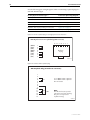
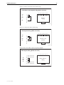
Dormant interfaces are included in the show interface command output
(Figure 30 on page 39 and Figure 31 on page 39) and in the SNMP interfaces
MIB, marked as swapped out. In other router or switch commands, however,
the router or switch behaves as though dormant interfaces do not exist.
Instances of higher-level modules such as LAPD, Q931, ISDN call control, PPP,
and IP do not become dormant when an interface becomes dormant. Instead
they behave as if the interface has stopped communicating, for example, as if
the cable has been unplugged.
The configuration script is not scanned for commands relating to hot-inserted
interfaces until the switch or router is restarted. These interfaces must be
configured manually.
C613-03023-00 REV P
Hardware Reference
39
The switch or router does not update the MAC address of any hot-swapped
Ethernet interface until the switch or router is restarted.
All other commands that show or set interface properties behave as if swapped
out interfaces do not exist. Commands that operate on multiple interfaces skip
swapped out interfaces. Commands specified explicitly to a dormant interface
display an error message.
Figure 30: Example output from the show interface command
Interfaces
sysUpTime:
00:00:46
DynamicLinkTraps.....Disabled
TrapLimit............20
Number of unencrypted PPP/FR links.....0
ifIndex Interface
ifAdminStatus ifOperStatus
ifLastChange
-----------------------------------------------------------------------------1
eth0
Up
Up
00:00:03
2
eth1
Up
Down
00:00:00
3
bri0
Up
Swapped out
00:00:43
4
eth2
Up
Swapped out
00:00:42
------------------------------------------------------------------------------
Interface name summary
Interface Full name
-----------------------------------------------------------------------------asyn0
asyn0
asyn1
asyn1
eth0
eth0
eth1
eth1
------------------------------------------------------------------------------
Figure 31: Example output from the show interface command for a specific interface
Interface..................
ifIndex..................
ifMTU....................
ifSpeed..................
ifAdminStatus............
ifOperStatus.............
ifLinkUpDownTrapEnable...
TrapLimit................
bri0
3
1712
144000
Up
Swapped out
Disabled
20
Interface Counters
ifInOctets .................. 52190
ifInUcastPkts ................ 3070
ifInNUcastPkts .................. 0
ifInDiscards .................... 0
ifInErrors ...................... 0
C613-03023-00 REV P
ifOutOctets ................. 52190
ifOutUcastPkts ............... 3071
ifOutNUcastPkts ................. 0
ifOutDiscards ................... 0
ifOutErrors ..................... 0
40
Port Interface Card
PIC Testing and Verification
Use the following methods to check that a PIC is installed and operating
correctly:
■
Verifying that the PIC has been recognised
■
Using a terminal to verify operation
■
Using the Test Facility to verify operation
■
Using an existing network to verify operation
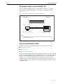
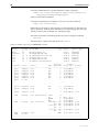
Verifying that the PIC has been recognised
To verify that the switch or router has recognised the PIC, turn on the switch or
router, and enter the command:
show system
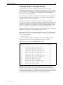
Figure 32 shows a typical output.
Figure 32: Example output from the show system command for a switch or router with PICs installed
Router System Status
Time 16:30:13 Date 26-Nov-2007.
Board
ID Bay Board Name
Host Id Rev
Serial number
-------------------------------------------------------------------------------Base
182
AT-AR745
0 M2-0
50038295
PIC
299
1 AT-AR021(S)-03 PIC BRI(S)
0 P2-0
78615636
NSM 4PIC
87
AT-AR040-00 NSM 4PIC
0 M4-0
42098017
-------------------------------------------------------------------------------Memory DRAM :131072 kB
FLASH : 16384 kB
-------------------------------------------------------------------------------SysDescription
CentreCOM AT-AR745 version 2.9.1-11 27-Sep-2007
SysContact
SysLocation
SysName
SysDistName
SysUpTime
396 ( 00:00:03 )
Boot Image
:
DEVELOPMENT Build
Software Version:
Release Version :
Patch Installed :
Territory
:
Country
:
Help File
:
Main PSU
RPS Monitor
745_107.fbr size 894264 13-Dec-2006
2.9.1-11 27-Sep-2007
2.9.1-11 27-Sep-2007
NONE
europe
none
700-291a.hlp
: On
: Off
Main Fan
: On
Configuration
Boot configuration file: boot.cfg
Current configuration: boot.cfg
Security Mode
: Disabled
C613-03023-00 REV P
Hardware Reference
41
The first part of the display shows details of cards installed in the switch or
router. There should be one entry for the switch or router base card and one
entry for each PIC installed. Both the serial number and the part name should
also be displayed.
If there is no entry for a PIC, then the boot process has not correctly detected
the presence of the PIC. The most likely causes are:
■
The connector on the PIC is not plugged into the PIC slot on the base card
correctly.
Repeat the installation process, inserting the PIC carefully into the lowest
numbered free bay, then tightening the screws firmly. Use the show system
command again to check that the PIC has been recognised.
■
The software version running on the switch or router does not support the
PIC. The AT-AR021 V3 hardware revision requires Software Version
2.9.1-13 or later. Use the show system command to check the software
version.
For more information about the show system command, see the Operation
chapter of the AlliedWare® Operating System Software Reference for your switch
or router.
If the display is still not correct, contact your authorised Allied Telesis
distributor or reseller.
Using a terminal to verify operation
PICs with asynchronous ports can be tested using a terminal set to:
■
9600 bps
■
8 data bits
■
1 stop bit
■
No parity
■
Hardware flow control
Verify that the terminal functions correctly by connecting it to the management
port (Console Port or RS-232 Terminal Port) on your switch or router and
pressing [Return] several times until the prompt is displayed.
Then connect the terminal to one of the PIC’s ports, and press [Return] several
times. If the prompt is displayed, the port is functioning correctly. If the prompt
is not displayed, the most likely cause is that the PIC’s ports are set to different
operational parameters. This can be verified by reconnecting the terminal to
the management port and then using the command:
show port=all
Compare the PIC’s port settings with the settings for the management port.
Any differences should be corrected by modifying the settings of the ports on
the PIC using the set asyn command from the Interfaces chapter of the
AlliedWare® Operating System Software Reference for your switch or router.
Reconnect the terminal to one of the PIC’s ports and press [Return] several
times. If the prompt is still not displayed, contact your authorised Allied Telesis
distributor or reseller.
C613-03023-00 REV P
42
Port Interface Card
Using the Test Facility to verify operation
The built-in Test Facility software provides the best method to properly verify
the correct operation of all PICs except the AT-AR026 PIC. For more
information about using the Test Facility, see “Test Facility” on page 43.
Using an existing network to verify operation
To test a PIC using an existing network, the PIC interfaces must be configured
correctly to route packets. For more information about configuring interfaces,
see the relevant chapter in the AlliedWare® Operating System Software Reference
for your switch or router.
C613-03023-00 REV P
Hardware Reference
43
Test Facility
The Test Facility is built into the AlliedWare operating system, and is the best
method to verify the correct operation of all PICs except the AT-AR026. Testing
can be performed while the switch or router is operational, but any interfaces
being tested are dedicated to the Test Facility. For more information about the
Test Facility, see the Test Facility chapter of the AlliedWare® Operating System
Software Reference.
The AT-AR026 PIC does not support the AlliedWare operating system’s
diagnostic or Test Facility features. AT-AR026 PICs include a switch chip that
switches independently of the switch, router, or NSM that the PIC is installed
in. The show interface command will show each correctly installed AT-AR026
as a single interface. The 10/100 “front side” Ethernet ports will not be shown.
PICs support a wide range of interface types, including Ethernet,
asynchronous, synchronous, Basic Rate ISDN and Primary Rate ISDN. Each
interface type can be tested independently using the Test Facility software.
For the Test Facility to operate, you must install a loopback plug or cable on
some interfaces. See Table 17 on page 43 for a list of interface types and their
loopback requirements. “Loopback Plugs for Testing Interfaces” on page 35
describes how to construct a loopback plug or cable.
Table 17: Loopback plugs, cables and devices required for testing PIC interfaces
Switch Interface
Asynchronous
Loopback plug, cable or test device required
RJ-45 asynchronous loopback plug.
Use one plug to individually test each port one by one, or all
ports can be tested simultaneously if sufficient loopback
plugs are available.
Ethernet LAN
(AT-AR022 ETH PIC only)
Ethernet loopback plug.
Basic Rate ISDN
BRI loopback plug for testing AT-AR021(S) V2 hardware
revision in NT mode.
The Test Facility software will detect (by looking for traffic)
if the transceiver is connected to a working LAN. If it detects
traffic, the transceiver test will abort.
The AT-AR021(S) V3 hardware revision and the
AT-AR021(U) PIC do not support the NT mode, so a
loopback plug can not be used. Internal loopback tests can
be run without a loopback plug.
For more complete testing, connect the BRI interface to an
external test device or NT mode device, then execute
conformance loopback tests and generate packets using
the enable bri ctest and disable bri ctest commands
from the Integrated Services Digital Network (ISDN) chapter
of the AlliedWare® Operating System Software Reference
for your switch or router.
C613-03023-00 REV P
Primary Rate ISDN
PRI loopback plug.
Synchronous
An external test device is required. Use a loopback to the
local DCE.
44
Port Interface Card
To run the Test Facility for a specific interface, use the command:
enable test interface={all|base|expansion|ethn|synn|portn|
brin|prin|engine|mac|mac0|mac1|mac2}
where n is the interface number.
To run the Test Facility for all interfaces on a PIC, use the command:
enable test interface=exp
If the tests are run with a loopback plug or external test device, the tests will
run for 4 minutes. If the tests are run without a loopback plug, they will stop
after about 30 seconds and display a warning message.
Test status and results can be displayed at any time, using the command:
show test
which produces a display like that shown in Figure 33.
Figure 33: Example output from the show test command
Board
ID Bay Board Name
Host Id Rev
Serial number
------------------------------------------------------------------------------Base
86
AT-RP24 Rapier 24
0 M3-3
50434040
NSM 4PIC
87
AT-AR040-00 NSM 4PIC
0 M4-0
42097500
PIC
75
0 AT-AR020-00 PIC E1/T1 PRI
0 M1-0
42197228
PIC
75
1 AT-AR023-00 PIC Sync
0 M2-1
54883467
PIC
75
2 AT-AR022-00 PIC Eth
0 M1-0
43225677
PIC
75
3 AT-AR021(S)-00 PIC BRI(S)
0 M3-0
50123345
Duration
Details
Interface State
Result
Type (minutes) Data( %OK ) Control
----------------------------------------------------------------------------port1
complete good
ALL
4
good(100.0)
port2
complete good
ALL
4
good(100.0)
port3
complete good
ALL
4
good(100.0)
port4
complete good
ALL
4
good(100.0)
port5
complete good
ALL
4
good(100.0)
port6
complete good
ALL
4
good(100.0)
port7
no test
.
.
.
port23 complete good
ALL
4
good(100.0)
port24 complete good
ALL
4
good(100.0)
asyn0
complete
good
eth0
testing
wait 12552 minutes
-
4
good(100.0)
good
trans
0
TP
5
BAD ( 56.2)
.
ENDEC
5
good(100.0)
MAC
5
good(100.0)
syn0
testing
wait continuous
RS-232dte 355
good(100.0) good
dce 355
good(100.0) good
X.21 dte 354
good(100.0) good .
dce
0
V.35 dte 354
good(100.0) good
dce
0
bri0
complete good
1000
good( 99.9) good
PRI0
no test
-----------------------------------------------------------------------------
C613-03023-00 REV P
Hardware Reference
45
The status of the tests for each interface is shown in the right-most column of
the output. For more information on the meanings of the other figures, see the
Test Facility chapter of the AlliedWare® Operating System Software Reference for
your switch or router.
If you are unsure about running the Test Facility, or have difficulty evaluating
the results, contact your authorised Allied Telesis distributor or reseller.
Troubleshooting
This section provides information on how to detect and resolve problems with PICs.
Performing the following tasks will eliminate the most common faults.
1.
Check that the PIC is correctly installed. See the Port Interface Card
Installation and Safety Guide for a step by step guide to installing PICs.
2.
Make sure the power cord is securely connected to the switch or router.
3.
Check that the power supply voltage to the switch or router is stable.
4.
Check that the correct data cables are being used and that their connections
are secure.
5.
Make sure that other network devices are working properly.
6.
Use the show install command to check that the latest software release is
loaded. The AlliedWare® Operating System Software Reference for your switch
or router has more information about obtaining and installing the latest
software release. In particular, the AT-AR021 V3 hardware revision requires
a switch or router running Software Version 2.9.1-13 or later.
7.
If the switch is malfunctioning, reboot it by pressing the recessed Reset
button or entering the command restart reboot. Alternatively, power off
and on the switch by disconnecting and reconnecting the main power
supply and, if connected, the RPS power.
Other sources of troubleshooting information are:
C613-03023-00 REV P
■
“Test Facility” on page 43
■
The Installation and Safety Guide or Quick Install Guide for your switch or
router, which can be downloaded from
www.alliedtelesis.com/support/software.
■
The Hardware Reference for your switch or router, which can be
downloaded from www.alliedtelesis.com/support/software.
■
www.alliedtelesis.com
46
Port Interface Card
Obtaining Documentation and Resources
Document set
The complete document set for Port Interface Cards includes the following:
■
this Hardware Reference, which contains detailed information on the
hardware features of Port Interface Cards
■
the Port Interface Card Installation and Safety Guide, which describes how to
install a Port Interface Card
■
the Network Service Module Installation and Safety Guide, which describes
how to install a Network Service Module
■
the Network Service Module Hardware Reference, which contains detailed
information on the hardware features of Network Service Modules
■
the Installation and Safety Guide, or Quick Install Guide and Safety and
Statutory Information for your switch or router, which describes how to
install the switch or router and includes important safety and statutory
information
■
the Hardware Reference for your switch or router, which contains detailed
information on the hardware features of your switch or router
■
the AlliedWare® Operating System Software Reference for your switch or
router, which contains detailed information on configuring WAN and
routing protocols to use PICs
You can download these documents and updates from
www.alliedtelesis.com/support/software.
You need Adobe® Acrobat® Reader® to view, search, or print these
documents. You can download it from www.adobe.com.
Other resources
How-To Notes describe a range of standard Allied Telesis solutions, and
include technical tips and guides to configuring specific hardware and
software features. You can download the latest How-To Notes from
www.alliedtelesis.com/resources/literature/howto.aspx.
MIBs supported by Allied Telesis products can be downloaded from
www.alliedtelesis.com/support/software.
Microsoft® Visio® stencils for Allied Telesis products can be downloaded from
www.alliedtelesis.com/resources/images/visio.aspx.
AT-TFTP Server for Windows is a TFTP (Trivial File Transfer Protocol) server for
transferring software versions, configuration scripts and other files between a
PC and your switch or router. You download AT-TFTP Server from
www.alliedtelesis.com/support/software.
CD-ROM
Some products ship with a Documentation and Tools CD-ROM, which includes:
■
the complete document set
■
Adobe® Acrobat® Reader®
■
AT-TFTP Server
■
Supported MIBs
■
How-To Notes, white papers, Microsoft® Visio® stencils and other
resources
■
Tryouts of networking software
C613-03023-00 REV P
Hardware Reference
Contacting us
C613-03023-00 REV P
47
With locations covering all of the established markets in North America, Latin
America, Europe, Asia, and the Pacific, Allied Telesis provides localized sales
and technical support worldwide. To find the representative nearest you, visit
us on the Web at www.alliedtelesis.com.