1
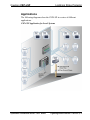
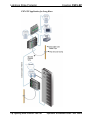
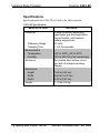
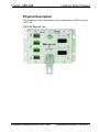
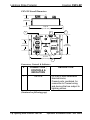
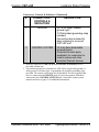
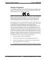
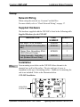
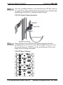
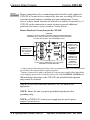
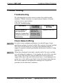
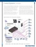
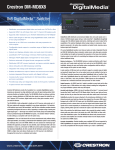
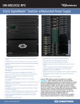
Crestron CSP-LSP
Cresnet® Lightning Strike Protector
Operations & Installation Guide
This document was prepared and written by the Technical Documentation department at:
Crestron Electronics, Inc.
15 Volvo Drive
Rockleigh, NJ 07647
1-888-CRESTRON
All brand names, product names and trademarks are the property of their respective owners.
©2008 Crestron Electronics, Inc.
Crestron CSP-LSP
Lightning Strike Protector
Contents
Cresnet® Lighting Strike Protector: Crestron CSP-LSP
1
Introduction ............................................................................................................................... 1
Features and Functions ................................................................................................ 1
Applications................................................................................................................. 3
Specifications .............................................................................................................. 6
Physical Description.................................................................................................... 7
Industry Compliance ................................................................................................. 10
Setup ........................................................................................................................................ 11
Network Wiring......................................................................................................... 11
Supplied Hardware .................................................................................................... 11
Installation ................................................................................................................. 11
Hardware Hookup ..................................................................................................... 13
Operation ................................................................................................................................. 15
Local CSP-LSP Operation......................................................................................... 15
Remote CSP-LSP Operation ..................................................................................... 15
Daisy Chaining .......................................................................................................... 16
Problem Solving ...................................................................................................................... 17
Troubleshooting......................................................................................................... 17
Check Network Wiring.............................................................................................. 17
Further Inquiries ........................................................................................................ 18
Future Updates .......................................................................................................... 18
Return and Warranty Policies .................................................................................................. 19
Merchandise Returns / Repair Service ...................................................................... 19
CRESTRON Limited Warranty................................................................................. 19
Operations & Installation Guide – DOC. 6643A
Contents • i
Crestron CSP-LSP
Lightning Strike Protector
®
Cresnet Lighting Strike
Protector: Crestron CSP-LSP
Introduction
The CSP-LSP is an accessory designed to protect a Crestron® control
system from lightning surges and other electrical disturbances brought
through the Cresnet control line. Four-stage lightning suppression
provides superior protection against damage to the control system caused
by lightning strikes to remote Cresnet devices and wiring, especially
outdoor equipment and underground cabling. It is also effective for
protection against transients picked up by indoor networks in any facility
that is particularly prone to near lightning strikes.
Features and Functions
• Sophisticated four-stage lightning suppression
• Protects control systems from surges and transients on the
Cresnet network
• Recommended for all outdoor Cresnet cable runs
• Multiple Cresnet ports for easy termination
• Includes grounding strap and clamp
The CSP-LSP provides protection for a single control system and any
portion of its Cresnet network. It may be located near the central
equipment cabinet to protect only the control system and centralized
devices, or it may be installed at the point of entry from an outdoor
Cresnet cable to protect the entire indoor Cresnet network. For networks
Operations & Installation Guide – DOC. 6643A
Lightning Strike Protector: CSP-LSP • 1
Lightning Strike Protector
Crestron CSP-LSP
that span multiple buildings, a separate CSP-LSP can be installed in each
building to protect all of the local devices within each building.
The CSP-LSP is designed for mounting to a wall or similar flat surface.
Two protected CONTROL SYSTEM ports are provided, paralleled for
easy daisy chaining to a second CSP-LSP or other Cresnet equipment.
Four paralleled DEVICE ports accommodate the connections from one
or more remote Cresnet wire runs. Two #10 ground lugs provide for
termination of the grounding cable. A three foot long braided ground
wire is included, complete with a copper saddle clamp for attachment to a
suitable utility ground, cold water pipe, or grounding rod. A bus bar is
also included for daisy chaining to a second CSP-LSP unit.
2 • Lightning Strike Protector: CSP-LSP
Operations & Installation Guide – DOC. 6643A
Crestron CSP-LSP
Lightning Strike Protector
Applications
The following diagrams show the CSP-LSP in a series of different
applications.
CSP-LSP Application for Local Systems
Operations & Installation Guide – DOC. 6643A
Lightning Strike Protector: CSP-LSP • 3
Lightning Strike Protector
Crestron CSP-LSP
CSP-LSP Application for Long Runs
4 • Lightning Strike Protector: CSP-LSP
Operations & Installation Guide – DOC. 6643A
Crestron CSP-LSP
Lightning Strike Protector
CSP-LSP Application for Multiple Building Systems
Operations & Installation Guide – DOC. 6643A
Lightning Strike Protector: CSP-LSP • 5
Lightning Strike Protector
Crestron CSP-LSP
Specifications
Specifications for the CSP-LSP are listed in the following table.
CSP-LSP Specifications
SPECIFICATION
Protection
Clamping Voltage
Clamping Time
Environmental
Temperature
Humidity
Enclosure
Dimensions
Height
Width
Depth
Weight
6 • Lightning Strike Protector: CSP-LSP
DETAILS
4-stage protection employing
spark gaps, gas discharge tubes,
current limiters, and transient
voltage suppressors
33 Volts
< 100 Picoseconds
-40º to 194ºF (-40º to 90ºC)
10% to 90% RH (non-condensing)
Zinc plated steel surface mount
box with (2) integral mounting
flanges
1.83 in (4.65 cm)
5.64 in (14.32 cm)
3.40 in (8.64 cm)
1.17 lbs (0.5 kg)
Operations & Installation Guide – DOC. 6643A
Crestron CSP-LSP
Lightning Strike Protector
Physical Description
This section provides information on the connections available on your
CSP-LSP.
CSP-LSP Physical View
Operations & Installation Guide – DOC. 6643A
Lightning Strike Protector: CSP-LSP • 7
Lightning Strike Protector
Crestron CSP-LSP
CSP-LSP Overall Dimensions
1.83 in
(4.65 cm)
5.64 in
(14.32 cm)
1
3
2
1.75 in
(4.45 cm)
3.40 in
(8.64 cm)
5.23 in
(13.29 cm)
2
Connectors, Controls & Indicators
#
CONNECTORS1,
CONTROLS &
INDICATORS
DESCRIPTION
1
DEVICE
(4) 4-pin 3.5mm detachable
terminal blocks;
Cresnet ports, paralleled, for
connection to Cresnet wiring
and devices that are subject to
lightning strikes.
(Continued on following page)
8 • Lightning Strike Protector: CSP-LSP
Operations & Installation Guide – DOC. 6643A
Crestron CSP-LSP
Lightning Strike Protector
Connectors, Controls & Indicators (Continued)
#
CONNECTORS1,
CONTROLS &
INDICATORS
DESCRIPTION
2
GROUND
3
CONTROL SYSTEM
(2) 10-32 studs, chassis
ground lugs2;
3 ft flat braided grounding strap
included;
Ground bus bar included for
daisy chaining to a second
CSP-LSP unit.
(2) 4-pin 5mm detachable
terminal blocks;
Protected Cresnet ports,
paralleled, for connection to
control system and other
protected Cresnet devices.
1. Interface connectors for DEVICE and CONTROL SYSTEMS ports are
provided with the unit.
2. For maximum protection, terminate the CSP-LSP to a good earth ground (i.e.
utility ground, cold water pipe, or grounding rod) using the grounding strap
provided. The control system must also be grounded. It is also suggested that
devices connected to the DEVICE ports be powered separately from those
connected to the CONTROL SYSTEM ports. Consult the control system
manuals and refer to page 13 for additional information.
Operations & Installation Guide – DOC. 6643A
Lightning Strike Protector: CSP-LSP • 9
Lightning Strike Protector
Crestron CSP-LSP
Industry Compliance
As of the date of manufacture, the CSP-LSP has been tested and found to
comply with specifications for CE marking and standards per EMC and
Radiocommunications Compliance Labelling.
NOTE: This device complies with part 15 of the FCC rules. Operation is
subject to the following two conditions: (1) this device may not cause
harmful interference and (2) this device must accept any interference
received, including interference that may cause undesired operation.
This equipment has been tested and found to comply with the limits for a
Class B digital device, pursuant to part 15 of the FCC Rules. These limits
are designed to provide reasonable protection against harmful
interference in a residential installation. This equipment generates, uses
and can radiate radio frequency energy and if not installed and used in
accordance with the instructions, may cause harmful interference to radio
communications. However, there is no guarantee that interference will
not occur in a particular installation. If this equipment does cause harmful
interference to radio or television reception, which can be determined by
turning the equipment off and on, the user is encouraged to try to correct
the interference by one or more of the following measures:
Reorient or relocate the receiving antenna.
Increase the separation between the equipment and receiver.
Connect the equipment into an outlet on a circuit different from
that to which the receiver is connected.
Consult the dealer or an experienced radio/TV technician for help.
10 • Lightning Strike Protector: CSP-LSP
Operations & Installation Guide – DOC. 6643A
Crestron CSP-LSP
Lightning Strike Protector
Setup
Network Wiring
When wiring the network use Crestron Certified Wire.
For more details, refer to “Check Network Wiring” on page 17.
Supplied Hardware
The hardware supplied with the CSP-LSP is listed in the following table.
Supplied Hardware for the CSP-LSP
DESCRIPTION
PART
NUMBER
QUANTITY
Nut, Keps, 10-32, External
Metal, Bracket (Grounding Bus
Bar)
Clamp, Pipe, Grounding, #14-6
AWG (Ground Clamp)
Cable Assembly, Grounding, 3
feet (Braided Ground Strap)
2004889
2019534
4
1
2019803
1
4505505
1
Installation
Wall
Mounting
Four mounting screw holes on the CSP-LSP allows the unit to be
mounted on a wall or flat surface. The size and type of screw is
dependant on the type of mounting surface. Hardware for mounting the
unit is not included. Refer to the illustration below.
CSP-LSP Installation
MOUNTING
SCREW HOLES
Operations & Installation Guide – DOC. 6643A
Lightning Strike Protector: CSP-LSP • 11
Lightning Strike Protector
Ground
Clamp
Crestron CSP-LSP
Necessary grounding hardware is provided with your CSP-LSP. Refer to
the image below when installing the braided ground strap (4505505) and
ground clamp (2019803) to a grounded cold water pipe.
CSP-LSP Ground Clamp Orientation
Daisy
Chaining
Daisy chain up to two CSP-LSP units together using the provided
grounding bus bar (2019534). Secure the grounding bar between two of
the provided kep nuts (2004889) onto the grounding stud. Refer to the
image below for proper orientation.
CSP-LSP Daisy Chaining
12 • Lightning Strike Protector: CSP-LSP
Operations & Installation Guide – DOC. 6643A
Crestron CSP-LSP
Lightning Strike Protector
Hardware Hookup
The CSP-LSP can be connected locally to protect a nearby control
system and Cresnet devices. The CSP-LSP can also be connected to
remote Cresnet devices or another CSP-LSP to provide protection to
Cresnet devices that are connected with substantially longer wire runs.
Make the necessary connections as called out in the illustrations below
and on the next page. Refer to “Network Wiring” on page 11 when
attaching the 4-position terminal block connectors. Be sure to carefully
review each hardware connection diagram before proceeding.
Local
Connections
Local connections refer to connections made from the CSP-LSP to Cresnet
devices which do not include wire runs exceeding 500 feet or wire runs
situated outdoors, including underground wire runs. Cresnet devices at these
local distance are referred to as local Cresnet devices.
Local Hardware Connections for the CSP-LSP
GROUND:
CONNECT TO GOOD EARTH GROUND USING PROVIDED BRAIDED
GROUND STRAP. SECURE END OF GROUNDING STRAP BETWEEN
TWO KEP NUTS ONTO THE GROUNDING STUD.
CRESNET:
CONNECT TO
CONTROL SYSTEM,
C2N-HBLOCK, OR
ANY LOCAL
CRESNET DEVICE
THAT IS TO BE
PROTECTED
CRESNET*:
CONNECT TO ANY
CRESNET DEVICE
DAISY CHAIN TO SECOND CSP-LSP USING
PROVIDED GROUND BUS BAR
* When making a connection to a remote Cresnet device or remote CSP-LSP, only
connect the data and ground wires.
Operations & Installation Guide – DOC. 6643A
Lightning Strike Protector: CSP-LSP • 13
Lightning Strike Protector
Remote
Connections
Crestron CSP-LSP
Remote connections refer to connections made from the locally connected
CSP-LSP to Cresnet devices connected by wire runs exceeding 500 feet or
wire runs situated outdoors, including wire runs underground. Cresnet
devices at these distant locations are referred to as remote Cresnet devices. A
CSP-LSP can be connected at a remote location to provide additional
protection to a unit or a series of remote Cresnet devices.
Remote Hardware Connections for the CSP-LSP
GROUND:
CONNECT TO GOOD EARTH GROUND USING PROVIDED BRAIDED
GROUND STRAP. SECURE END OF GROUNDING STRAP BETWEEN
TWO KEP NUTS ONTO THE GROUNDING STUD.
CRESNET:
CONNECT TO
C2N-HBLOCK, OR
ANY REMOTE
CRESNET
DEVICE
CRESNET 1:
CONNECT TO
LOCAL CSP-LSP
OR ANOTHER
CSP-LSP
DAISY CHAIN TO SECOND CSP-LSP USING
PROVIDED GROUND BUS BAR
CRESNET:
CONNECT TO
C2N-HBLOCK,
ANY REMOTE
CRESNET
DEVICE, OR
POWER SUPPLY 2
1
Connect only the data and ground wires. Devices connected to these CSP-LSP units must
be provided with a separate power supply if required.
2
Remote Cresnet devices must be powered by a separate power supply either individually
or by supplying power to the Cresnet network via one of the CONTROL SYSTEM ports.
When making connections to the CSP-LSP, the included braided ground
strap cannot be extended.
NOTE: Do not daisy chain more than two CSP-LSP units in one
application.
NOTE: Ensure the unit is properly grounded using the provided
grounding strap.
NOTE: A CNPWS-75 Cresnet power supply may be used to power
remote Cresnet devices.
14 • Lightning Strike Protector: CSP-LSP
Operations & Installation Guide – DOC. 6643A
Crestron CSP-LSP
Lightning Strike Protector
Operation
The CSP-LSP can be connected either locally or remotely, while up to
two CSP-LSP devices may be daisy chained together in either connection
configuration.
Local CSP-LSP Operation
Locally, one of the CONTROL SYSTEM ports must be connected to
the control system. The other CONTROL SYSTEM port provides
maximum protection for another Cresnet device or if multiple local
devices exist, should be connected to a C2N-HBLOCK, which can
distribute protection for up to 15 Cresnet peripherals.
The DEVICE ports can also offer some protection locally or are
designed to carry data and ground to remote Cresnet devices or another
CSP-LSP.
When connecting the CSP-LSP unit in a local connection configuration,
only one of the grounding studs needs to be connected. The second
grounding stud may be left unconnected.
Remote CSP-LSP Operation
One DEVICE port delivers data and ground to the remote CSP-LSP.
These signals can be carried to yet another remote CSP-LSP via one of
the other DEVICE ports.
At the remote location, one CONTROL SYSTEM port should be
connected to a power supply so that all remote Cresnet devices can be
properly powered. The other CONTROL SYSTEM port provides
maximum protection for another Cresnet device or if multiple local
devices exist, should be connected to a C2N-HBLOCK, which can
distribute protection for up to 15 Cresnet peripherals.
When connecting the CSP-LSP unit in a remote connection
configuration, only one of the grounding studs needs to be connected.
The second grounding stud may be left unconnected.
Operations & Installation Guide – DOC. 6643A
Lightning Strike Protector: CSP-LSP • 15
Lightning Strike Protector
Crestron CSP-LSP
Daisy Chaining
Up to two CSP-LSP units can be daisy chained when a C2N-HBLOCK is
not a practical option. Daisy chaining two CSP-LSP units provide up to
four protected CONTROL SYSTEM ports.
When CSP-LSP units are being daisy-chained together, connect both of
the available grounding studs to a good earth ground using the grounding
straps provided with each unit.
16 • Lightning Strike Protector: CSP-LSP
Operations & Installation Guide – DOC. 6643A
Crestron CSP-LSP
Lightning Strike Protector
Problem Solving
Troubleshooting
The following table provides corrective action for possible trouble
situations. If further assistance is required, please contact a Crestron
customer service representative.
CSP-LSP Troubleshooting
TROUBLE
POSSIBLE
CAUSE(S)
CORRECTIVE
ACTION
Device appears to
be charred and
branch of connected
Cresnet units are not
functioning.
Device has
failed due to
lightning strike
or power surge.
Replace CSP-LSP.
Check Network Wiring
Use the Right
Wire
In order to ensure optimum performance over the full range of your
installation topology, Crestron Certified Wire and only Crestron Certified
Wire may be used. Failure to do so may incur additional charges if
support is required to identify performance deficiencies because of using
improper wire.
Strip and Tin
Wire
When daisy-chaining Cresnet units, strip the ends of the wires carefully
to avoid nicking the conductors. Twist together the ends of the wires that
share a pin on the network connector and tin the twisted connection.
Apply solder only to the ends of the twisted wires. Avoid tinning too far
up the wires or the end becomes brittle. Insert the tinned connection into
the Cresnet connector and tighten the retaining screw. Repeat the
procedure for the other three conductors.
Operations & Installation Guide – DOC. 6643A
Lightning Strike Protector: CSP-LSP • 17
Lightning Strike Protector
Crestron CSP-LSP
Further Inquiries
If you cannot locate specific information or have questions after
reviewing this guide, please take advantage of Crestron's award winning
customer service team by calling the Crestron corporate headquarters at
1-888-CRESTRON [1-888-273-7876]. For assistance in your local time
zone, refer to the Crestron website (www.crestron.com/offices) for a
listing of Crestron worldwide offices.
You can also log onto the online help section of the Crestron website
(www.crestron.com/onlinehelp) to ask questions about Crestron products.
First-time users will need to establish a user account to fully benefit from
all available features.
Future Updates
As Crestron improves functions, adds new features and extends the
capabilities of the CSP-LSP, additional information may be made
available as manual updates. These updates are solely electronic and
serve as intermediary supplements prior to the release of a complete
technical documentation revision.
Check the Crestron website periodically for manual update availability
and its relevance. Updates are identified as an “Addendum” in the
Download column.
18 • Lightning Strike Protector: CSP-LSP
Operations & Installation Guide – DOC. 6643A
Crestron CSP-LSP
Lightning Strike Protector
Return and Warranty Policies
Merchandise Returns / Repair Service
1.
No merchandise may be returned for credit, exchange or service without prior authorization
from CRESTRON. To obtain warranty service for CRESTRON products, contact an
authorized CRESTRON dealer. Only authorized CRESTRON dealers may contact the factory
and request an RMA (Return Merchandise Authorization) number. Enclose a note specifying
the nature of the problem, name and phone number of contact person, RMA number and
return address.
2.
Products may be returned for credit, exchange or service with a CRESTRON Return
Merchandise Authorization (RMA) number. Authorized returns must be shipped freight
prepaid to CRESTRON, 6 Volvo Drive, Rockleigh, N.J. or its authorized subsidiaries, with
RMA number clearly marked on the outside of all cartons. Shipments arriving freight collect
or without an RMA number shall be subject to refusal. CRESTRON reserves the right in its
sole and absolute discretion to charge a 15% restocking fee plus shipping costs on any
products returned with an RMA.
3.
Return freight charges following repair of items under warranty shall be paid by CRESTRON,
shipping by standard ground carrier. In the event repairs are found to be non-warranty, return
freight costs shall be paid by the purchaser.
CRESTRON Limited Warranty
CRESTRON ELECTRONICS, Inc. warrants its products to be free from manufacturing defects in materials
and workmanship under normal use for a period of three (3) years from the date of purchase from
CRESTRON, with the following exceptions: disk drives and any other moving or rotating mechanical
parts, pan/tilt heads and power supplies are covered for a period of one (1) year; touchscreen display and
overlay components are covered for 90 days; batteries and incandescent lamps are not covered.
This warranty extends to products purchased directly from CRESTRON or an authorized CRESTRON
dealer. Purchasers should inquire of the dealer regarding the nature and extent of the dealer's warranty, if
any.
CRESTRON shall not be liable to honor the terms of this warranty if the product has been used in any
application other than that for which it was intended or if it has been subjected to misuse, accidental
damage, modification or improper installation procedures. Furthermore, this warranty does not cover any
product that has had the serial number altered, defaced or removed.
This warranty shall be the sole and exclusive remedy to the original purchaser. In no event shall
CRESTRON be liable for incidental or consequential damages of any kind (property or economic damages
inclusive) arising from the sale or use of this equipment. CRESTRON is not liable for any claim made by a
third party or made by the purchaser for a third party.
CRESTRON shall, at its option, repair or replace any product found defective, without charge for parts or
labor. Repaired or replaced equipment and parts supplied under this warranty shall be covered only by the
unexpired portion of the warranty.
Except as expressly set forth in this warranty, CRESTRON makes no other warranties, expressed or
implied, nor authorizes any other party to offer any warranty, including any implied warranties of
merchantability or fitness for a particular purpose. Any implied warranties that may be imposed by law are
limited to the terms of this limited warranty. This warranty statement supersedes all previous warranties.
Trademark Information
All brand names, product names and trademarks are the sole property of their respective owners. Windows is a registered trademark
of Microsoft Corporation. Windows95/98/Me/XP/Vista and WindowsNT/2000 are trademarks of Microsoft Corporation.
Operations & Installation Guide – DOC. 6643A
Lightning Strike Protector: CSP-LSP • 19
Crestron Electronics, Inc.
15 Volvo Drive Rockleigh, NJ 07647
Tel: 888.CRESTRON
Fax: 201.767.7576
www.crestron.com
Operations & Installation Guide – DOC. 6643A
(2019895)
02.08
Specifications subject to
change without notice.