1
QAM256
Digital Video Modulator
and Upconverter
Installation and Operation Manual
TM077
Revision 4.0
Radyne Corporation • 3138 E. Elwood St. • Phoenix, AZ 85034 • (602) 437-9620 • Fax: (602) 437-4811 • www.radn.com
QAM256 Digital Video Modulator and Upconverter
Warranty Policy
Warranty Policy
WP
Radyne Corp. (Seller) warrants the items manufactured and sold by Radyne Corp. to be free of defects in
material and workmanship for a period of two (2) years from date of shipment Radyne Corp.’s obligation
under its warranty is limited in accordance with the periods of time and all other conditions stated in all
provisions of this warranty.
This warranty applies only to defects in material and workmanship in products manufactured by Radyne
Corp. Radyne Corp. makes no warranty whatsoever concerning products or accessories not of its
manufacture. Repair, or at the option of Radyne Corp., replacement of the Radyne Corp. products or
defective parts therein shall be the sole and exclusive remedy for all valid warranty claims.
Warranty Period
The applicable warranty period shall commence on the date of shipment from a Radyne Corp. facility to the
original purchaser and extend for the stated period following the date of shipment. Upon beginning of the
applicable Radyne Corp. warranty period, all customers’ remedies shall be governed by the terms stated or
referenced in this warranty. In-warranty repaired or replacement products or parts are warranted only for the
remaining unexpired portion of the original warranty period applicable to the repaired or replaced products or
parts. Repair or replacement of products or parts under warranty does not extend the original warranty
period.
Warranty Coverage Limitations
The following are expressly not covered under warranty:
1.
Any loss, damage and/or malfunction relating in any way to shipping, storage, accident, abuse,
alteration, misuse, neglect, failure to use products under normal operating conditions, failure to use
products according to any operating instructions provided by Radyne Corp., lack of routine care
and maintenance as indicated in any operating maintenance instructions, or failure to use or take
any proper precautions under the circumstances.
2.
Products, items, parts, accessories, subassemblies, or components which are expendable in
normal use or are of limited life, such as but not limited to, bulbs, fuses, lamps, glassware, etc.
Radyne Corp. reserves the right to revise the foregoing list of what is covered under this warranty.
Warranty Replacement and Adjustment
Radyne Corp. will not make warranty adjustments for failures of products or parts, which occur after the
specified maximum adjustment period. Unless otherwise agreed, failure shall be deemed to have occurred
no more than seven (7) working days before the first date on which Radyne Corp. receives a notice of
failure. Under no circumstances shall any warranty exceed the period stated above unless expressly agreed
to in writing by Radyne Corp.
Liability Limitations
This warranty is expressly in lieu of and excludes all other express and implied warranties, Including but not
limited to warranties of merchantability and of fitness for particular purpose, use, or applications, and all
other obligations or liabilities on the part of Radyne Corp., unless such other warranties, obligations, or
liabilities are expressly agreed to in writing by Radyne Corp.
All obligations of Radyne Corp. under this warranty shall cease in the event its products or parts thereof
have been subjected to accident, abuse, alteration, misuse or neglect, or which have not been operated and
maintained in accordance with proper operating instructions.
TM077 – Rev. 4.0
iii
Warranty Policy
QAM256 Digital Video Modulator and Upconverter
In no event shall Radyne Corp. be liable for Incidental, consequential, special or resulting loss or damage of
any kind howsoever caused. Radyne Corp.’s liability for damages shall not exceed the payment, if any,
received by Radyne Corp. for the unit or product or service furnished or to be furnished, as the case may be,
which is the subject of claim or dispute.
Statements made by any person, including representatives of Radyne Corp., which are inconsistent or in
conflict with the terms of this warranty, shall not be binding upon Radyne Corp. unless reduced to writing
and approved by an officer of Radyne Corp.
Warranty Repair Return Procedure
Before a warranty repair can be accomplished, a Repair Authorization must be received. It is at this time
that Radyne Corp. will authorize the product or part to be returned to the Radyne Corp. facility or if field
repair will be accomplished. The Repair Authorization may be requested in writing or by calling:
Radyne Corporation
3138 E. Elwood St.
Phoenix, Arizona 85034 (USA)
ATTN: Customer Support
Phone: (602) 437-9620
Fax: (602) 437-4811
Any product returned to Radyne Corp. for examination must be sent prepaid via the means of transportation
indicated as acceptable to Radyne Corp. Return Authorization Number must be clearly marked on the
shipping label. Returned products or parts should be carefully packaged in the original container, if possible,
and unless otherwise indicated, shipped to the above address.
Non-Warranty Repair
When a product is returned for any reason, Customer and its shipping agency shall be responsible for all
damage resulting from improper packing and handling, and for loss in transit, not withstanding any defect or
nonconformity in the product. By returning a product, the owner grants Radyne Corp. permission to open
and disassemble the product as required for evaluation. In all cases, Radyne Corp. has sole responsibility
for determining the cause and nature of failure, and Radyne Corp.’s determination with regard thereto shall
be final.
iv
TM077 - Rev. 4.0
QAM256 Digital Video Modulator and Upconverter
Preface
Preface
P
This manual provides installation and operation information for the Radyne QAM256 Digital Video
Modulator and Upconverter. This is a technical document intended for use by engineers,
technicians, and operators responsible for the operation and maintenance of the QAM256.
Conventions
Whenever the information within this manual instructs the operator to press a pushbutton switch
or keypad key on the Front Panel, the pushbutton or key label will be shown enclosed in "less
than" (<) and "greater than" (>) brackets. For example, the Reset Alarms Pushbutton will be
shown as <RESET ALARMS>, while a command that calls for the entry of a ‘7’ followed by
‘ENTER’ Key will be represented as <7,ENTER>.
Cautions and Warnings
A caution icon indicates a hazardous situation that if not avoided, may result in minor or moderate
injury. Caution may also be used to indicate other unsafe practices or risks of property damage.
A warning icon indicates a potentially hazardous situation that if not avoided, could result in death
or serious injury.
A note icon identifies information for the proper operation of your equipment, including helpful
hints, shortcuts, or important reminders.
TM077 – Rev. 4.0
v
Preface
QAM256 Digital Video Modulator and Upconverter
Trademarks
Product names mentioned in this manual may be trademarks or registered trademarks of their
respective companies and are hereby acknowledged.
Copyright
©2008, Radyne Corp. This manual is proprietary to Radyne Corp. and is intended for the
exclusive use of Radyne Corp.’s customers. No part of this document may in whole or in part, be
copied, reproduced, distributed, translated or reduced to any electronic or magnetic storage
medium without the express written consent of a duly authorized officer of Radyne Corp.
Disclaimer
This manual has been thoroughly reviewed for accuracy. All statements, technical information,
and recommendations contained herein and in any guides or related documents are believed
reliable, but the accuracy and completeness thereof are not guaranteed or warranted, and they
are not intended to be, nor should they be understood to be, representations or warranties
concerning the products described. Radyne Corp. assumes no responsibility for use of any
circuitry other than the circuitry employed in Radyne Corp. systems and equipment. Furthermore,
since Radyne Corp. is constantly improving its products, reserves the right to make changes in
the specifications of products, or in this manual at any time without notice and without obligation
to notify any person of such changes.
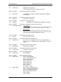
Record of Revisions
Revision
Level
Date
1.0
1.1
2.0
1-1-99
3-30-99
4-5-01
3.0
3.1
3.2
12-3-02
1-20-04
12-29-04
4.0
4-29-08
Reason for Change
New Release
Clarified DVB ASI information, revised data rates in Specifications section
Merged TM077 QAM256 Digital Video Modulator with TM084 QAM256
Digital Video Modulator and Upconverter Manuals
Revised and reformatted Technical Manual. Revised Figure 5-1.
Revised and reformatted Technical Manual.
Changed Power Output Accuracy from ± .50 to ± 1.0 dB. Reformatted
manual.
Correct product performance stated.
Comments or Suggestions Concerning this Manual
Comments or suggestions regarding the content and design of this manual are appreciated. To
submit comments, please contact the Radyne Corp. Customer Service Department.
vi
TM077 - Rev. 4.0
QAM256 Digital Video Modulator and Upconverter
Table of Contents
Table of Contents
ToC
Section 1 - Introduction _______________________________________________ 1-1
1.0 Introduction ______________________________________________________ 1-1
Section 2 - Installation ________________________________________________ 2-1
2.0 Installation Requirements ___________________________________________ 2-1
2.1 Unpacking _______________________________________________________ 2-1
2.2 Removal and Assembly ____________________________________________ 2-2
2.3 Mounting Considerations ___________________________________________ 2-2
Section 3 - Theory of Operation ________________________________________ 3-1
3.0 Theory of Operation _______________________________________________ 3-1
3.1 QAM256 Operation ________________________________________________ 3-1
Section 4 - User Interfaces ____________________________________________ 4-1
4.0 User Interfaces ___________________________________________________ 4-1
4.1 Front Panel User Interface __________________________________________ 4-1
4.1.1 LCD Front Panel Display __________________________________________ 4-2
4.1.2 Cursor Control Arrow Keys ________________________________________ 4-2
4.1.3 Numeric Keypad_________________________________________________ 4-2
4.1.4 Front Panel LED Indicators ________________________________________ 4-3
4.2 Parameter Setup __________________________________________________ 4-3
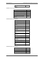
4.3 Front Panel Control Screen Menus____________________________________ 4-4
4.3.1 Main Menus ____________________________________________________ 4-4
4.3.2 Modulator Menu Options and Parameters _____________________________ 4-4
4.3.3 Interface Menu Options and Parameters ______________________________ 4-5
4.3.4 Monitor Menu Options and Parameters _______________________________ 4-6
4.3.5 Alarms Menu Options and Parameters _______________________________ 4-6
4.3.6 System Menu Options and Parameters _______________________________ 4-7
4.3.7 Test Menu Options and Parameters _________________________________ 4-7
4.4 Terminal Port User Interface _________________________________________ 4-7
TM077 – Rev. 4.0
vii
Table of Contents
QAM256 Digital Video Modulator and Upconverter
4.5 Connecting the Terminal ____________________________________________ 4-8
4-6 Terminal Screens _________________________________________________ 4-8
4.7 QAM256 Terminal Mode Control ____________________________________ 4-12
4.8 Sample Terminal Mode Control Screen Menus _________________________ 4-12
4.9 Management Information Base Structure ______________________________ 4-13
4.10 Simple Network Management Protocol (SNMP) ________________________ 4-13
4.11 The Management Information Base (MIB) ____________________________ 4-13
4.12 Directory ______________________________________________________ 4-13
4.13 Mgmt _________________________________________________________ 4-13
4.14 Experimental ___________________________________________________ 4-13
4.15 Private ________________________________________________________ 4-13
Section 5 - Rear Panel Interfaces _______________________________________ 5-1
5.0 QAM256 Rear Panel Interfaces/Connections ____________________________ 5-1
5.1 AC Power _______________________________________________________ 5-1
5.2 FAULT Connection ________________________________________________ 5-1
5.3 TX MON Port_____________________________________________________ 5-2
5.4 TX IF Port _______________________________________________________ 5-2
5.5 ASI/Parallel Interface Connections ____________________________________ 5-4
5.5.1 TX PARALLEL Connector _________________________________________ 5-4
5.5.2 REMOTE Connector _____________________________________________ 5-4
5.5.3 TX ASI Connector _______________________________________________ 5-4
5.6 ASI and Advanced ASI Interfaces_____________________________________ 5-4
5.7 Framing/Interface Compatibility ______________________________________ 5-5
5.8 Optional DVB Interface _____________________________________________ 5-5
Section 6 - Maintenance and Troubleshooting ____________________________ 6-1
6.0 Periodic Maintenance ______________________________________________ 6-1
Section 7 - Technical Specifications ____________________________________ 7-1
7.0 Introduction ______________________________________________________ 7-1
7.1 Specifications Without Cable Upconverter ______________________________ 7-1
7.1.1 IF Interface _____________________________________________________ 7-1
7.1.2 Baseband Interface ______________________________________________ 7-1
7.1.3 Remote Interface ________________________________________________ 7-1
viii
TM077 - Rev. 4.0
QAM256 Digital Video Modulator and Upconverter
Table of Contents
7.1.4 Physical _______________________________________________________ 7-1
7.2 Specifications With Cable Upconverter_________________________________ 7-1
7.2.1 RF Interface ____________________________________________________ 7-2
7.2.2 Baseband Interface ______________________________________________ 7-2
7.2.3 Remote Interface ________________________________________________ 7-2
7.2.4 Physical _______________________________________________________ 7-2
Appendix A - Product Options _________________________________________ A-1
Appendix A.0 QAM256 Data Rates_______________________________________ A-1
Appendix B - SNMP MIB ______________________________________________ B-1
Appendix C - RLLP Protocol ___________________________________________ C-1
C.0 Remote Operations _______________________________________________ C-1
C.1 Host Computer Remote Communications ______________________________ C-1
C.1.1 Protocol Structure _______________________________________________ C-1
C.1.2 Protocol Wrapper________________________________________________ C-2
C.1.3 Frame Description Bus Handshaking ________________________________ C-3
C.1.4 Global Response Operational Codes ________________________________ C-4
C.1.5 Collision Avoidance ______________________________________________ C-5
C.1.6 Software Compatibility____________________________________________ C-6
C.1.7 Flow Control and Task Processing __________________________________ C-6
C.1.8 RLLP Summary _________________________________________________ C-7
C.2 Remote Port Modes of Operation_____________________________________ C-9
Glossary ___________________________________________________________ G-1
TM077 – Rev. 4.0
ix
Table of Contents
x
QAM256 Digital Video Modulator and Upconverter
TM077 - Rev. 4.0
QAM256 Digital Video Modulator and Upconverter
Introduction
Introduction
1
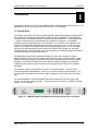
This chapter provides an overview of the QAM256 Digital Video Modulator and Upconverter. The
QAM256 may be referred to in this manual as “the unit”, or the modulator”.
1.0 Introduction
The Radyne Corporation new DVB-compliant QAM256 Digital Video Modulator and Upconverter
meet all DVB requirements for transmission of digital video over broadband coaxial cable and
microwave radio. The QAM256 features 4 QAM to 256 QAM modulation, 1 - 52 Mbps data rate,
1 - 8 MHz channel spacing, and Reed-Solomon Forward Error Correction. The QAM256
modulator supports output frequency of 35 to 37 MHz or 43 to 44 MHz or 50 to 862 MHz. The
upconverter combines the QAM Modulator and Frequency converter into a 1 Rack Unit (RU)
chassis (1.75” high) which eliminates the need for an additional converter unit. The modulator
also supports field-changeable RS-422 Parallel, DVB Parallel, M2P Parallel, ASI, and other
standard interfaces. Remote Monitor and Control interface is provided through either an RS-485
or Ethernet Remote Port using SNMP protocol.
The QAM256 provides efficient bandwidth utilization for digital video distribution systems.
MMDS, LMDS and Cable Television systems all benefit from this innovative modulator. QAM
modulation solves the problem of providing multiple video and data channels within bandwidth
limitations. The Radyne QAM256 Upconverter has the versatility to adapt to any terrestrial
broadband medium and give system operators full management and control of the available
bandwidth.
The modulator meets the specifications of the ITU-T Recommendation; J.83 Annex A&B
(Telecommunication Standardization of the ITU for Television and Sound Transmission). The
microprocessor-based Monitor and Control (M&C) operates from the front panel or the remote
port.
The Interface Module is a field-changeable module that contains either RS-422, M2P, DVB,
Parallel, ASI, or other standard interface. The interface can accept data in an MPEG-2 transport
format, or as random data.
Figure 1-1. QAM256 Digital Video Modulator and Cable Upconverter Front Panel
TM077 – Rev. 4.0
1-1
Introduction
1-2
QAM256 Digital Video Modulator and Upconverter
TM077 - Rev. 4.0
QAM256 Digital Video Modulator and Upconverter
Installation
Installation
2
This section provides unpacking and installation instructions, and a description of external
connections and backward alarm information.
2.0 Installation Requirements
The QAM256 Modem is designed to be installed within any standard 19-inch wide equipment
cabinet or rack, and requires one rack unit (RU) of mounting space (1.75 inches) vertically and
17¾ inches of depth. Including cabling, a minimum of 20 inches of rack depth is required. The
rear panel of the modem is designed to have power enter from the left and IF Cabling enter from
the right when viewed from the rear of the unit. Data and Control Cabling can enter from either
side although they are closer to the center. The unit can be placed on a table or suitable surface
if required.
There are no user-serviceable parts or configuration settings
located inside the QAM256 Chassis. There is a potential shock
hazard internally at the Power Supply Module. DO NOT open the
QAM256 Chassis under any circumstances. Always disconnect the
main plug before servicing of any kind.
Before initially applying power to the unit, it is a good idea to disconnect
the transmit output from the operating ground station equipment. This is
especially true if the current QAM256 configuration settings are
unknown,
where
incorrect
settings
could
disrupt
existing
communications traffic.
2.1 Unpacking
The QAM256 Digital Video Modulator and Upconverter was carefully packaged to avoid damage
and should arrive complete with the following items for proper installation:
QAM256 Unit
Power Cord, with applicable AC Connector
Installation and Operation Manual
TM077 – Rev. 4.0
2-1
Installation
QAM256 Digital Video Modulator and Upconverter
2.2 Removal and Assembly
Carefully unpack the unit and ensure that all of the above items are in the carton. If the Prime AC
power available at the installation site requires a different Power Cord/AC Connector, then
arrangements to receive the proper device will be necessary before proceeding with the
installation.
The QAM256 unit is shipped fully assembled and does not require removal of the covers for any
purpose in installation. Should the power cable AC connector be of the wrong type for the
installation, either the cable or the power connector end should be replaced. The power supply
itself is designed for universal application using from 100 to 240 VAC, 50 to 60 Hz, 1 A.
Always ensure that power is removed from the QAM256 before removing
or installing a UIM. Failure to do so may cause damage to the equipment.
2.3 Mounting Considerations
When mounted in an equipment rack, adequate ventilation must be provided. The ambient
temperature in the rack should preferably be between 10° and 35°C, and held constant for best
equipment operation. The air available to the rack should be clean and relatively dry. The
modems may be stacked one on top of the other to a maximum of 10 consecutive units before
providing one (1) RU of space for airflow. Modems should not be placed immediately above a
high-heat or EMF Generator to ensure the output signal integrity and proper receive operation.
Do not mount the QAM256 in an unprotected outdoor location where there is direct contact with
rain, snow, wind or sun. The only tools required for rack mounting the QAM256 are four (4)
customer supplied rack-mounting screws and the appropriate screwdriver. Rack mounting
brackets are an integral part of the cast front bezel of the unit and are not removable.
Shielded cables with the shield terminated to the conductive backshells are required in order to
meet EMC directives. Cables with insulation flammability ratings of 94 VO or better are required
in order to meet low voltage directives.
2-2
TM077 - Rev. 4.0
QAM256 Digital Video Modulator and Upconverter
TM077 – Rev. 4.0
Installation
2-3
QAM256 Digital Video Modulator and Upconverter
Theory of Operation
Theory of Operation
3
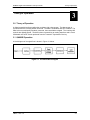
3.0 Theory of Operation
A digital terrestrial interface supplies the modulator with a data stream. The data stream is
synchronized if the incoming stream is framed. The data is scrambled, and FEC is added. The
data is then convolutionally encoded, punctured, then constellation mapped. The resulting I&Q
symbols are digitally filtered. The data is then converted into an analog waveform and is vector
modulated onto an RF Carrier produced from the Transmit IF Synthesizer Circuitry.
3.1 QAM256 Operation
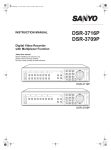
A block diagram of the signal flow is shown in Figure 3-1 below.
Figure 3-1. Functional Block Diagram
TM077 – Rev. 4.0
3-1
Theory of Operation
3-2
QAM256 Digital Video Modulator and Upconverter
TM077 - Rev. 4.0
QAM256 Digital Video Modulator and Upconverter
User Interfaces
User Interfaces
4
4.0 User Interfaces
Operation of the QAM256 consists of controlling the unit operating parameters and monitoring
status and responses via one of the control interfaces. The two user interfaces available from the
Front Panel are Front Panel Control, and Terminal Mode Control (not currently available). Either
of these methods may be used separately or together to monitor and control the QAM256.
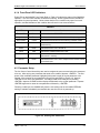
4.1 Front Panel User Interface
The Front Panel of the QAM256 allows for complete control and monitor of all QAM256
parameters and functions via the Keypad, LCD Display and Status LEDs.
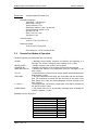
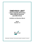
The front panel layout is shown in Figure 4-1, showing the location and labeling of the front panel.
The front panel is divided into four functional areas: the LCD Front Panel Display, the Cursor
Control Arrow Keys, the Numeric Keypad, and the Front Panel LED Indicators, each described
below in Table 4-1.
1
2
3
4
Figure 4-1. QAM256 Front Panel
Table 4-1.
Item Number
Description
Function
1
LCD Front Panel Display
Displays QAM256 Operating parameters
and Configuration data
2
Cursor Control Arrow Keys
Controls the up, down, right and left motion
of the cursor in the LCD Display window
3
Numeric Keypad
Allows entry of numeric data and Clear and
Enter function keys
4
Front Panel LED Indicators
See Paragraph 4.1.2 below for an itemized
description of these LEDs
TM077 – Rev. 4.0
4-1
User Interfaces
QAM256 Digital Video Modulator and Upconverter
4.1.1 LCD Front Panel Display
The front panel display is a 2 line by 16-character LCD display. The display is lighted and the
brightness can be set to increase when the front panel is currently in use. The LCD display
automatically dims after a period of inactivity. The display has two distinct areas showing current
information. The upper area shows the current parameter being monitored, such as ‘Frequency’
or ‘Data Rate’. The lower line shows the current value of that parameter. The LCD display is a
single entry window into the large matrix of parameters that can be monitored and set from the
Front Panel.
4.1.2 Cursor Control Arrow Keys
A set of ‘Arrow’ or ‘Cursor’ keys (↑), (↓), (→), (←), is used to navigate the parameter currently
being monitored or controlled. Table 4-2 describes the functions available at the Front Panel.
4.1.3 Numeric Keypad
A 10 Key Numeric Keypad with 2 additional keys for the ‘Enter’ and ‘Clear’ function allows the
entry of data into the system. Table 4-2 describes the functions available at the Front Panel.
Table 4-2.
Edit Mode Key Functions (Front Panel Only)
Parameter
Type
0–9
↑
Fixed Point Changes Digit Toggles ±
Decimal
(If Signed)
↓
←
→
‘Clear’ &
←
‘Clear’ &
→
Toggles ±
(If Signed)
Moves
Cursor 1
Position
Left
Moves
Cursor 1
Position
Right
N/A
N/A
Moves
Cursor 1
Position
Left
Moves
Cursor 1
Position
Right
N/A
N/A
Unsigned Changes Digit Increments Decrements
Hexadecimal
Digit Value Digit Value
Enumerated
N/A
Previous
Value in
List
Next
Value in
List
N/A
N/A
N/A
N/A
N/A
N/A
Moves
Cursor 1
Position
Left
Moves
Cursor 1
Position
Right
N/A
N/A
IP Address Changes Digit Increments Decrements
Digit Value Digit Value
Moves
Cursor 1
Position
Left
Moves
Cursor 1
Position
Right
N/A
N/A
Text Strings
Moves
Cursor 1
Position
Left
Moves
Cursor 1
Position
Right
Clears to
Left of
Cursor
Inclusive
Clears to
Right of
Cursor
Inclusive
Date/ Time Changes Digit
4-2
Changes
Character
Increments Decrements
Character
Character
Value
Value
TM077 - Rev. 4.0
QAM256 Digital Video Modulator and Upconverter
User Interfaces
4.1.4 Front Panel LED Indicators
Eight LEDs on the QAM256 Front Panel (Refer to Table 4-3) indicate the status of the QAM256’s
operation. The LED colors maintain a consistent meaning. Green signifies that the indication is
appropriate for normal operation, Yellow means that there is a condition not proper for normal
operation, and Red indicates a fault condition that will result in lost communications.
Table 4-3.
LED
Color
Function
Transmit On
Green
Major Alarm
Red
Minor Alarm
Yellow
Indicates that a transmit receive warning condition exists.
Test Mode
Yellow
Indicates that the modulator is involved in a current test
mode activity.
Power
Green
Indicates that the unit is turned on.
Fault
Red
Event
Yellow
Indicates that a condition or event has occurred that the unit
has stored in memory.
Remote
Green
Indicates that the unit is set to respond to the remote control
or terminal input.
Indicates that the QAM256 Transmitter is turned on.
Indicates that the transmit direction has failed, losing traffic.
Indicates a hardware fault for the unit.
4.2 Parameter Setup
The four Cursor Control Arrow Keys are used to navigate the menu tree and select the parameter
to be set. After arriving at a parameter that needs to be modified, depress <ENTER>. The first
space of the modifiable parameter highlights (blinks) and is ready for a new parameter to be
entered. After entering the new parameter using the keypad (Refer to Figure 4-2), depress
<ENTER> to lock in the new parameter. If a change needs to be made prior to pressing
<ENTER>, depress <CLEAR> and the display defaults back to the original parameter. Depress
<ENTER> again and re-enter the new parameters followed by <ENTER>.
Following a valid input, the QAM256 will place the new setting into the nonvolatile EEPROM
making it available immediately and available the next time the unit is powered-up.’
Figure 4-2. Entering New Parameters
TM077 – Rev. 4.0
4-3
User Interfaces
QAM256 Digital Video Modulator and Upconverter
4.3 Front Panel Control Screen Menus
The QAM256 Front Panel Control Screens are broken down into sections under several Main
Menus.
4.3.1 Main Menus
Modulator
Interface
Monitor
Alarms
System
Test
4.3.2 Modulator Menu Options and Parameters
Frequency:
{50 MHz – 862 MHz}
Cable Upconverter
{35 MHz – 37 MHz}
Optional
{43 MHz – 44 MHz}
Optional
Encoder Type:
ITU-T J.83 Annex A {DVB/DAVIC}
ITU-T J.83 Annex B {DigiCipherII}
Modulation:
{4, 16, 32, 64, 128, 256 QAM}
Data Rate:
{1 - 52 Mbps}
Refer to Table A-1.
Interleaver:
DVB {12, 17}
Trellis {204, 1}
Spectrum:
{Normal, Inverted}
Tx Power:
{+60 dBmV to +45 dBmV}
With Cable Upconverter
{+0.0dBm to –25.0 dBm}
Without Cable Converter
Tx Enable:
{On, Off}
Symbol Rate:
{7.1 Msps maximum}
Roll Off:
{0.12, 0.15, 0.18}
Framing:
{MPEG 187, 188, 204}
4-4
TM077 - Rev. 4.0
QAM256 Digital Video Modulator and Upconverter
User Interfaces
4.3.3 Interface Menu Options and Parameters
Interface Type:
{ PAR M2P, Parallel, ASI, Advanced ASI}
Clock Polarity:
{Normal, Inverted}
Data Invert:
{Normal, Inverted}
TM077 – Rev. 4.0
4-5
User Interfaces
QAM256 Digital Video Modulator and Upconverter
4.3.4 Monitor Menu Options and Parameters
Event Buff:
Displays a history of events recorded in the event buffer.
A maximum of 40 events may be stored in the buffer.
Upon receipt of the 41st event, the first received event is
automatically deleted, and so on, maintaining the
maximum 40 events.
Press Clr to Erase Events:
Clears the contents of the Event Buffer.
Tx Enabled:
{On, Off}
4.3.5 Alarms Menu Options and Parameters
Major Tx (menu):
Mod Hardware:
{Pass, Fail}
Tx Syn Lock:
{Pass, Fail}
Data PLL Lock:
{Pass, Fail}
Mod3 Lock:
{Pass, Fail}
RF SynU Lock:
{Pass, Fail}
RF SynD Lock:
{Pass, Fail}
Minor Tx (menu):
Data Actv:
{Pass, Fail}
Clock Actv:
{Pass, Fail}
FIFO Fault:
{Pass, Fail}
Code Clk Active:
{Pass, Fail}
Common (menu):
4-6
M&C Hardware:
{Pass, Fail}
INT Hardware:
{Pass, Fail}
TM077 - Rev. 4.0
QAM256 Digital Video Modulator and Upconverter
User Interfaces
4.3.6 System Menu Options and Parameters
Control Mode:
{Front Panel, Computer}
Date:
Displays the current date.
Time:
Displays the current time.
Bklt Level:
{0 – 99 seconds, 0 = No Timeout}
Key Click:
{On, Off}
Emulation:
TBD
Firmware Version:
M&C Version
Last Rate:
{Auto, Symbol, Data}
4.3.7 Test Menu Options and Parameters
LED Test:
{Normal}
Carrier:
{Normal, CW}
4.4 Terminal Port User Interface
The Remote Port (J5) of the QAM256 allows for complete control and monitoring of all QAM256
parameters and functions via an RS-232 Serial Interface, or RS-485 for RLLP Protocol. ‘Terminal
Mode’ can be entered from the front panel by selecting “System” and then “Control Mode”
followed by “Terminal”. The baud rate and evaluation type can be changed at the front panel by
using the System>Baud Rate Menu.
The Terminal Control Mode is menu-driven and the allowable values for each item number will be
shown. To change an item, type in its number followed by <ENTER>. If the parameter to be
changed requires a numeric value, enter the number followed by <ENTER> If the parameter is
non-numeric, press <SPACE> to cycle through the list of available entries.
Items that do not have ID numbers are Status only and cannot be
changed.
TM077 – Rev. 4.0
4-7
User Interfaces
QAM256 Digital Video Modulator and Upconverter
4.5 Connecting the Terminal
1.
Connect the computer to the QAM256 Remote Connector (J5) on the rear of the unit
using the RS-232 Cable.
2.
Enable the terminal by selecting Terminal Mode (located under the System - Control
Mode Menu) from the front panel.
3.
Verify that your emulation software is set to the following:
8 data bits
no parity
1 stop bit
Modify the QAM256 selection, if necessary, to match the settings (the Front Panel
‘SYSTEM’ Sub-Menu contains all the Terminal Emulation Controls).
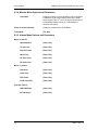
4.6 Terminal Screens
1.
Modem configuration can be monitored and controlled via a full screen presentation of
current settings and status. The <Esc> Key redraws the entire screen and aborts input
any time. The Spacebar refreshes the status area and is used to scroll through selection
when in user input mode.
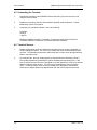
2.
To modify an item, the user simply presses its terminal selection followed by <Enter>.
The modem responds by presenting the options available and requesting input. If the
input is multiple choices, the user is prompted to use the Spacebar to scroll to the desired
selection and then press <Enter>. An input can be aborted at any time by pressing
<Esc>. Invalid input keys cause an error message to be displayed on the terminal.
Some input or display status only appears when the user has the right access levels.
4-8
TM077 - Rev. 4.0
QAM256 Digital Video Modulator and Upconverter
User Interfaces
Main Menu Screen:
TM077 – Rev. 4.0
4-9
User Interfaces
QAM256 Digital Video Modulator and Upconverter
Modulator Control Screen:
Event Buffer Screen:
4-10
TM077 - Rev. 4.0
QAM256 Digital Video Modulator and Upconverter
User Interfaces
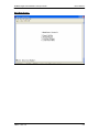
Alarm Status Screen:
Latched Alarm Screen:
TM077 – Rev. 4.0
4-11
User Interfaces
QAM256 Digital Video Modulator and Upconverter
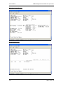
Interface Controls Screen:
4.7 QAM256 Terminal Mode Control
‘Terminal Mode’ can be entered from the front panel by selecting ‘System’ and then ‘Control
Mode’ followed by ‘Terminal.’ The default settings for the terminal are as follows:
1.
19,200 Baud;
2.
8 Data bits;
3.
1 stop bit;
4.
No parity.
The baud rate can be changed at the front panel by using the System>Baud Rate menu. The
new baud rate does not take effect until power to the unit has been recycled.
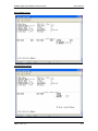
4.8 Sample Terminal Mode Control Screen Menus
The Terminal Control Mode is menu-driven as shown in the screen captures below. The
allowable values for each item number are shown. To change an item, type in its number
followed by <ENTER>. If the parameter to be changed requires a numeric value, enter the
number followed by <ENTER>. If the parameter is non-numeric, press <SPACE> to cycle
through the list of available entries. Note that the items that do not have ID numbers are Status
only and cannot be changed.
Note: This feature has not been currently implemented.
4-12
TM077 - Rev. 4.0
QAM256 Digital Video Modulator and Upconverter
User Interfaces
4.9 Management Information Base Structure
This section defines the terminology and hierarchy associated with management information base
structure at Radyne Corporation.
4.10 Simple Network Management Protocol (SNMP)
Simple Network Management Protocol (SNMP), as its name suggests, is a relatively simple
protocol by which management information for a network device may be inspected and/or altered
by remote administrators.
4.11 The Management Information Base (MIB)
Management objects are defined in the Management Information Base (MIB), which uses a
hierarchical naming scheme. Within this scheme, each object is identified by an Object Identifier
(OID), a sequence of non-negative integers that uniquely describes the path taken through the
hierarchical structure.
MIB objects may then be specified either from the Root (which has no designator), or alternatively
from anywhere within the hierarchical structure.
For example: 1.3.6.1.4.1.2591.4 is equivalent to {iso(1). org(3). dod(6). internet(1). private(4).
enterprises(1). Radyne(2591). RCS10L(4)} (See Figure 1).
In general, we are mainly concerned with just two groups that reside in the internet subtree,
namely the mgmt, and private groups. For completeness however, the four major groups are
discussed below:
4.12 Directory
{internet 1}
1.3.6.1.1
This area was reserved to describe how the OSI directory structure may be used in the Internet.
To date this has not been implemented and therefore is of little interest to us.
4.13 Mgmt
{internet 2}
1.3.6.1.2
This area was reserved to describe objects in the standard MIB. As RFCs defining new groups
are ratified, the Internet Assigned Numbers Authority (IANA) assigns new group IDs.
4.14 Experimental
{internet 3}
1.3.6.1.3
This subtree provides an area where experimentation is carried out. Only those organizations
directly involved in the experiment have any interest in this subtree.
4.15 Private
{internet 4}
1.3.6.1.4
This is possible the most important area of the MIB, since it is within this subtree that vendors
place objects specific to their particular devices. Beneath the private branch, there is a subtree
called enterprises, beneath which each vendor may define its own structure. Vendors are
assigned Private Enterprise Numbers (PENs) that uniquely identify them. They may then place
all objects specific to their devices in this tree, provided of course that the object conforms to the
format defined by SMI. Radyne Corporation’s Private Enterprise Number is 2591. Other
products are added to Radyne Corporation’s subtree as they become remotely manageable
through SNMP.
TM077 – Rev. 4.0
4-13
User Interfaces
QAM256 Digital Video Modulator and Upconverter
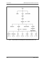
Figure 1. Object Identifiers in the Management Information Base (Sheet 1 of 2)
4-14
TM077 - Rev. 4.0
QAM256 Digital Video Modulator and Upconverter
User Interfaces
Figure 1. Object Identifiers in the Management Information Base (Sheet 2 of 2)
Refer to Appendix B for the QAM256 MIB.
TM077 – Rev. 4.0
4-15
User Interfaces
4-16
QAM256 Digital Video Modulator and Upconverter
TM077 - Rev. 4.0
QAM256 Digital Video Modulator and Upconverter
Rear Panel Interfaces
Rear Panel Interfaces
5
This section discusses the electrical interfaces available from the rear panel. All locations are as
viewed from the rear of the unit unless otherwise specified.
5.0 QAM256 Rear Panel Interfaces/Connections
All QAM256 Interfaces/Connections are made to labeled connectors located on the rear of the
unit. The connector definitions below are those on the QAM256 unit. Any connection interfacing
to the QAM256 must be the appropriate mating connector. Refer to Figure 2-1 for connector
locations. All connectors are as viewed from the rear of the unit unless noted.
Figure 5-1. QAM256 Back Panel
5.1 AC Power
The unit is powered from a 100 – 240 VAC, 50 – 60 Hz source located on the left side of the unit.
Integrated into the power entry module is the Power On/Off Rocker Switch. Power consumption
for the unit is 1A. The power cord/connector assembly is a supplied item. A chassis ground
connection (#10-32 threaded) stud, is located to the lower right of the AC Power Cord
Connection.
5.2 FAULT Connection
The QAM256 has two Form-C dry contact alarm relays onboard and a Fault connector located on
the rear panel. The two relays are designated “1” and “2”. The Modem Alarm B Port (J6) can be
used for modem fault status. The physical interface is a female 9-Pin D-Sub Connector. This
port is an open collector input. The pinouts are listed in Table 5-1.
Table 5-1. FAULT Connection - 9-Pin Female
D-Sub - J6
Pin No.
Connection
1
Relay 1 NC
2
Relay 1 C
3
Relay 1 NO (Minor Alarm)
4
Ground
5
NC
6
Mod Fault (Open Collector)
7
Relay 2 NC
TM077 – Rev. 4.0
5-1
Rear Panel Interfaces
QAM256 Digital Video Modulator and Upconverter
8
Relay 2 C
9
Relay 2 NO (Major Alarm)
5.3 TX MON Port
The Transmit Monitor Port (J8) is a Female BNC Connector, -20 dB Monitor Port.
5.4 TX IF Port
The Transmit IF Port (J9) is a Female BNC Connector.
The RS-485 Remote Connector (J3) is a 9-Pin Female D-Sub Connector. The pinouts are listed
in Table 5-2.
Table 5-2. REMOTE Connection - 9-Pin Female D-Sub – J3
Pin No.
Signal Name
Description
Direction
1
Tx (B)
Transmit Data (+)
Output
5
GND
Ground
---
6
Tx (A)
Transmit Data (-)
Output
8
Rx (B)
Receive Data (+)
Input
9
Rx (A)
Receive Data (-)
Input
The RS-422 Transmit Parallel Connector (J1) is a 25-Pin Female D-Sub Connector. The pinouts
are listed in Table 5-3.
Table 5-3. PARALLEL Connection - 25-Pin Female
D-Sub – J3
5-2
Pin No.
Signal Name
Direction
1
OUTCLK
Output
14
OUTCLK
Output
2
BCLK+
Input
15
BCLK-
Input
3
SYNC+
Input
16
SYNC-
Input
4
VALID+
Input
17
VALID-
Input
5
D0+
Input
18
D0-
Input
6
D1+
Input
TM077 - Rev. 4.0
QAM256 Digital Video Modulator and Upconverter
Rear Panel Interfaces
19
D1-
Input
7
D2+
Input
20
D2-
Input
8
D3+
Input
21
D3-
Input
9
D4+
Input
22
D4-
Input
10
D5+
Input
23
D5-
Input
11
D6+
Input
24
D6-
Input
12
D7+
Input
25
D7-
Input
13
GND
---
TM077 – Rev. 4.0
5-3
Rear Panel Interfaces
QAM256 Digital Video Modulator and Upconverter
5.5 ASI/Parallel Interface Connections
5.5.1 TX PARALLEL Connector
The RS-422 Transmit Parallel Connector (J1) is a 25-Pin Female D-Sub Connector. The pinouts
are listed in Table 5-3.
5.5.2 REMOTE Connector
The RS-485 Remote Connector (J3) is a 9-Pin Female D-Sub Connector. The pinouts are listed
in Table 5-2.
5.5.3 TX ASI Connector
The Transmit ASI Connector (J4) is a Female BNC Connector.
5.6 ASI and Advanced ASI Interfaces
The QAM256 has two ASI options that apply to different uses. The Normal ASI option interfaces
to data sources that conform to the DVB ASI Specification. The DVB ASI Specification requires
data sources to transmit the ASI/DVB transport stream at a constant data rate and packet gap
with no variation in time from one sync byte to the next.
The Advanced ASI Option is designed to interface with data sources that do not conform to the
DVB ASI Specification. This card will handle transport streams with inconsistent data rates or
packet gaps. The modulator’s data rate must be set greater than the fastest data rate that can be
expected from the data source. When the data is not available at that data rate, the modulator
will output DVB Null Frames (see Table 5-4) until enough data has been received to fill a packet.
In this method, the modulator’s input buffer will not be overrun and the demodulator will not lose
lock due to inconsistent packet delivery.
Table 5-4. DVB Null Packet Description
Null Packet =
Sync Byte
PID
Count
Data
Hex Value
47
IFFF
0000
FF - FF
Byte Number
0
1-2
3-4
5 - 187
5-4
TM077 - Rev. 4.0
QAM256 Digital Video Modulator and Upconverter
Rear Panel Interfaces
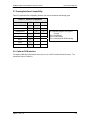
5.7 Framing/Interface Compatibility
Table 5-5 represents the compatibility between the various interfaces and framing types.
Table 5-5. Interface Compatibility
Interface/Framing
187
188
Parallel/DVB/M2P
X
X
Normal ASI
X
X
X
X
X
Advanced ASI
HSSI
X
T3, E3
X
STS-1
X
Serial
X
ECL
X
204
X = Interface Supports This type of
Framing
187 = No Framing
188 = DVB Framing
204 = Reed-Solomon DVB Framing
5.8 Optional DVB Interface
The Optional RS-422 DVB Interface Connector (J1) is a 25-Pin Female D-Sub Connector. The
pinouts are listed in Table 5-6.
TM077 – Rev. 4.0
5-5
Rear Panel Interfaces
QAM256 Digital Video Modulator and Upconverter
Table 5-6. J1 Optional DVB RS-422 Parallel Connection - 25-Pin Female
D-Sub – J3
5-6
Pin No.
Signal Name
Direction
1
Clock +
Input
2
System GND
Ground
3
D7 +
Input
4
D6 +
Input
5
D5 +
Input
6
D4 +
Input
7
D3 +
Input
8
D2 +
Input
9
D1 +
Input
10
D0 +
Input
11
DVALID +
Input
12
PSYNC +
Input
13
Cable Shield
Input
14
Clock -
Input
15
System GND
Ground
16
D7 -
Input
17
D6 -
Input
18
D5 -
Input
19
D4 -
Input
20
D3 -
Input
21
D2 -
Input
22
D1 -
Input
23
D0 -
Input
24
DVALID -
Input
25
SYNC -
Input
TM077 - Rev. 4.0
QAM256 Digital Video Modulator and Upconverter
TM077 – Rev. 4.0
Rear Panel Interfaces
5-7
QAM256 Digital Video Modulator and Upconverter
Maintenance and Troubleshooting
Maintenance and Troubleshooting
6
6.0 Periodic Maintenance
The QAM256 modulator requires no periodic field maintenance procedures. Should a unit be
suspected of a defect in field operations after all interface signals are verified, the correct
procedure is to replace the unit with another known working QAM256. If this does not cure the
problem, wiring or power should be suspect.
There is no external fuse on the QAM256. The fuse is located on the
power supply assembly inside the case, and replacement is not
intended in the field.
TM077 – Rev. 4.0
6-1
Maintenance and Troubleshooting
6-2
QAM256 Digital Video Modulator and Upconverter
TM077 - Rev. 4.0
QAM256 Digital Video Modulator and Upconverter
Technical Specifications
Technical Specifications
7
7.0 Introduction
This section defines the technical performance parameters and specifications for the QAM256
Digital Video Modulator and Upconverter.
7.1 Specifications Without Cable Upconverter
Data Rate:
Modulation:
Roll Off:
FEC:
1 - 55 Mbps
4, 16, 32, 64, 128, and 256 QAM (7 Msps Maximum)
12, 15, and 18% Selectable
204/188 Reed-Solomon with I = 1 - 204 programmable
Forney Convolutional Interleaver meets J.83 Annex A,
Annex B
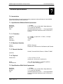
7.1.1 IF Interface
Frequency:
Level:
Spurious:
Impedance:
43 – 44 MHz, or optional 35 – 37 MHz, 1 Hz Steps
0 to –25 dBm
-50 dBc
75Ω
7.1.2 Baseband Interface
Format:
Physical:
MPEG-2 Transport
Parallel, ASI, Advanced ASI, DVB Parallel, M2P Parallel
7.1.3 Remote Interface
RS-485, Terminal RS232, Ethernet, 10 Base-T SNMP
(Optional)
7.1.4 Physical
Chassis Size:
1.75” H x 19” W x 17.75” D
(4.445cm H x 48.26cm W x 48.085cm D)
Power:
Environmental:
100 – 240 VAC, 50/60 Hz or –48 VDC (Optional)
0 - 50°C, < 95% Humidity @ 25°C
7.2 Specifications With Cable Upconverter
Data Rate:
Modulation:
Roll Off:
FEC:
TM077 – Rev. 4.0
1 - 55 Mbps
4, 16, 32, 64, 128, and 256 QAM (7 Msps Maximum)
12, 15, and 18% Selectable
204/188 Reed-Solomon with I = 1 - 204 programmable
Forney Convolutional Interleaver meets J.83 Annex A,
Annex B
7-1
Technical Specifications
QAM256 Digital Video Modulator and Upconverter
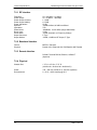
7.2.1 RF Interface
Frequency:
Power Output:
Power Output Accuracy:
Power Output Stability:
Power Adjustment:
Spurious:
Impedance:
Phase Noise:
Return Loss:
Carrier Mute:
Output Connector:
Output Monitor:
50 – 862 MHz, 1 Hz Steps
45 – 60 dBmV, 1 dB Steps
± 1.0 dB
± 0.5 dB
25 dB
-50 dBc In-Band, 45 dB Out-of-Band
75Ω
-88 dBc/Hz, 10 kHz Offset (Single Side-Band)
16 dB
-55 dB, Automatic on Frequency Change
F-Type
-20 dB, ± 3 dB from RF Output, F-Type
7.2.2 Baseband Interface
Format:
Physical:
MPEG-2 Transport
Parallel, ASI, Advanced ASI, DVB Parallel, M2P Parallel
7.2.3 Remote Interface
RS-485, Terminal RS232, Ethernet, 10 Base-T
(Optional)
7.2.4 Physical
Chassis Size:
1.75” H x 19” W x 17.75” D
(4.445cm H x 48.26cm W x 48.085cm D)
Power:
Environmental:
100 – 240 VAC, 50/60 Hz or –48 VDC (Optional)
0 - 50°C, < 95% Humidity @ 25°C
7-2
TM077 - Rev. 4.0
QAM256 Digital Video Modulator and Upconverter
TM077 – Rev. 4.0
Technical Specifications
7-3
QAM256 Digital Video Modulator and Upconverter
Product Options
Product Options
A
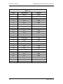
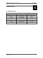
A.0 QAM256 Data Rates
Table A-1. Maximum Symbol Rate = 7.1 Msps
Minimum
Maximum
Modulation Type
1 Mbps
13.086275 Mbps
4 QAM
1 Mbps
26.172549 Mbps
16 QAM
1 Mbps
32.715686 Mbps
32 QAM
1 Mbps
39.258824 Mbps
64 QAM
1 Mbps
45.801961 Mbps
128 QAM
1 Mbps
52.345098 Mbps
256 QAM
TM077 – Rev. 4.0
A-1
Product Options
A-2
QAM256 Digital Video Modulator and Upconverter
TM077 - Rev. 4.0
QAM256 Digital Video Modulator and Upconverter
SNMP MIB
SNMP MIB
B
QAM256-MIB DEFINITIONS ::= BEGIN
IMPORTS
enterprises
FROM RFC1155-SMI
OBJECT-TYPE
FROM RFC-1212;
-- groups in Radyne specific MIB
radyne OBJECT IDENTIFIER ::= { enterprises 2591 }
qam256 OBJECT IDENTIFIER ::= { radyne 6 }
radQAM256ModNVStatus OBJECT IDENTIFIER ::= { qam256 1 }
radQAM256ModStatus OBJECT IDENTIFIER ::= { qam256 2 }
radQAM256TxCarrierControl OBJECT-TYPE
SYNTAX INTEGER
{ off(1), on(2) }
ACCESS read-write
STATUS current
DESCRIPTION
"Turns carrier on and off"
::= { radQAM256ModNVStatus 1 }
radQAM256TxTransmitPower OBJECT-TYPE
SYNTAX INTEGER
(-250..0, 450..600)
ACCESS read-write
STATUS current
DESCRIPTION
"Selects the Tx power level in dBm from +0.0 to -25.0 for the QAM25636Mhz and QAM25644Mhz. There is an
implied decimal point. For example a value of -39 represents a transmit power level of -3.9 dBm. Selects the Tx
power level in dBv from +45.0 to +60.0 for the QAM256cable. There is an implied decimal point. For example a
value of 500 represents a transmit power level of 50.0 dBv."
::= { radQAM256ModNVStatus 2 }
radQAM256TxIFFrequency OBJECT-TYPE
SYNTAX INTEGER
(35000000..862000000)
ACCESS read-write
STATUS current
DESCRIPTION
"Selects IF frequency in Hz. The frequency range of the QAM25636Mhz is 35 MHz to 37 MHz, of the
QAM25644Mhz is 43 Mhz to 45 MHz and of the QAM256Cable is 50 Mhz to 862 Mhz."
::= { radQAM256ModNVStatus 3 }
radQAM256TxDataRate OBJECT-TYPE
SYNTAX INTEGER
(1000000..56800000)
ACCESS read-write
STATUS current
DESCRIPTION
"Selects the data rate in BPS. The data rate is variable from 1 Mbps to 56.8 Mbps."
::= { radQAM256ModNVStatus 4 }
radQAM256TxSymbolRate OBJECT-TYPE
SYNTAX INTEGER
(1000000..7100000)
ACCESS read-write
STATUS current
DESCRIPTION
"Selects the symbol rate in SPS. The symbol rate is variable from 1Msps to 7.1Msps."
::= { radQAM256ModNVStatus 5 }
TM077 – Rev. 4.0
B-1
Product Options
QAM256 Digital Video Modulator and Upconverter
radQAM256TxFraming OBJECT-TYPE
SYNTAX INTEGER
{ framing187(1),
framing188(2),
framing204(3),
data(4) }
ACCESS read-write
STATUS current
DESCRIPTION
"Selects Unframed, MPEG Sync Byte and MPEG Sync Byte plus Reed-Solomon"
::= { radQAM256ModNVStatus 6 }
radQAM256TxModulation OBJECT-TYPE
SYNTAX INTEGER
{ qam4(1),
qam16(2),
qam32(3),
qam64(4),
qam128(5),
qam256(6) }
ACCESS read-write
STATUS current
DESCRIPTION
"Selects the QAM modulation type."
::= { radQAM256ModNVStatus 7 }
radQAM256TxEncoderInterleaver OBJECT-TYPE
SYNTAX INTEGER
{ annexa1204(1), annexa2102(2), annexa368(3),
annexa451(4), annexa634(5), annexa1217(6), annexa1712(7), annexa346(8), annexa514(9), annexa683(10),
annexa1022(11), annexa2041(12), annexb1281(13), annexb1282(14), annexb642(15), annexb1283(16),
annexb324(17), annexb1284(18), annexb168(19), annexb1285(20), annexb816(21), annexb1286(22),
annexb432(23), annexb1287(24), annexb264(25), annexb1288(26), annexb1128(27) }
ACCESS read-write
STATUS current
DESCRIPTION
"Selects the interleaver type."
::= { radQAM256ModNVStatus 8 }
radQAM256TxRolloff OBJECT-TYPE
SYNTAX INTEGER
{ alpha012(1),
alpha015(2),
alpha018(3) }
ACCESS read-write
STATUS current
DESCRIPTION
"Selects the alpha factor for the spectrum shape."
::= { radQAM256ModNVStatus 9 }
radQAM256TxInterfaceType OBJECT-TYPE
SYNTAX INTEGER
{ g703stsl(1), g703e3(2), g703t3(3), asi(4),
advancedasi(5), paralleldvb(6), parallelm2p(7), ecl(8), hssi(9), smpte(10), g703t3t1(11), g703e3e1(12) }
ACCESS read-write
STATUS current
DESCRIPTION
"Selects the interface type.SMPTE, g703t3t1 and g703e3-e1 are not yet
implemented."
::= { radQAM256ModNVStatus 10 }
radQAM256TxSpectrum OBJECT-TYPE
SYNTAX INTEGER
{ normal(1),
inverted(2) }
ACCESS read-write
STATUS current
DESCRIPTION
"Inverts the direction of rotation for the modulation."
::= { radQAM256ModNVStatus 11 }
B-2
TM077 – Rev. 4.0
QAM256 Digital Video Modulator and Upconverter
SNMP MIB
radQAM256TxClockPolarity OBJECT-TYPE
SYNTAX INTEGER
{ normal(1),
inverted(2) }
ACCESS read-write
STATUS current
DESCRIPTION
"Selects clock polarity for Tx terrestrial clock relative to Tx data."
::= { radQAM256ModNVStatus 12 }
radQAM256TxDataPolarity OBJECT-TYPE
SYNTAX INTEGER
{ normal(1),
inverted(2) }
ACCESS read-write
STATUS current
DESCRIPTION
"Selects data polarity"
::= { radQAM256ModNVStatus 13 }
radQAM256TxCarrierMode OBJECT-TYPE
SYNTAX INTEGER
{ normal(1),
cw(2) }
ACCESS read-write
STATUS current
DESCRIPTION
"Normal sets the carrier to normal CW causes the modulator to output pure carrier"
::= { radQAM256ModNVStatus 14 }
radQAM256TxMajorAlarm1Mask OBJECT-TYPE
SYNTAX INTEGER
(0..255)
ACCESS read-write
STATUS current
DESCRIPTION
"Major Alarm 1 mask:
Bit 0=Mod Hardware fault 1=Fault
Bit 1=Tx Synthesizer fault
Bit 2=Tx Data PLL lock fault
Bit 3=Tx Framing Lock (Unused)
Bit 4=Mod Chip 1 Lock fault (Unused)
Bit 5=Mod Chip 2 Lock fault (Unused)
Bit 6=Mod Chip 3 Lock fault (Current chip used)
Bit 7=Spare
0 = Mask, 1 = Allow"
::= { radQAM256ModNVStatus 15 }
radQAM256TxMajorAlarm2Mask OBJECT-TYPE
SYNTAX INTEGER
(0..255)
ACCESS read-write
STATUS
current
DESCRIPTION
"Major alarm 2 mask:
Bits 0..7 = spares
0=mask, 1=allow"
::= { radQAM256ModNVStatus 16 }
radQAM256TxMinorAlarm1Mask OBJECT-TYPE
SYNTAX INTEGER
(0..255)
ACCESS
read-write
STATUS
current
DESCRIPTION
"Minor Alarm 1 mask:
Bit 0=Clock activity detect fault
Bit 1=Data activity detect fault
Bit 2..7=Spares
0=Mask, 1=Allow"
::= { radQAM256ModNVStatus 17 }
TM077 – Rev. 4.0
B-3
Product Options
QAM256 Digital Video Modulator and Upconverter
radQAM256TxMinorAlarm2Mask OBJECT-TYPE
SYNTAX INTEGER
(0..255)
ACCESS
read-write
STATUS
current
DESCRIPTION
"Minor alarm 2 mask:
Bits 0..7 = spares
0=mask, 1=allow"
::= { radQAM256ModNVStatus 18 }
radQAM256CommonAlarm1Mask OBJECT-TYPE
SYNTAX INTEGER
(0..255)
ACCESS read-write
STATUS
current
DESCRIPTION
"Common alarm 1 mask:
Bit 0 = Interface hardware fault mask
Bit 1 = M&C hardware fault mask
Bits 2..7 = spares
0=mask, 1=allow"
::= { radQAM256ModNVStatus 19 }
radQAM256CommonAlarm2Mask OBJECT-TYPE
SYNTAX INTEGER
(0..255)
ACCESS read-write
STATUS
current
DESCRIPTION
"Common alarm 2 mask:
Bits 0..7 = spares
0=mask, 1= allow"
::= { radQAM256ModNVStatus 20 }
radQAM256TxControlMode OBJECT-TYPE
SYNTAX INTEGER
{ local(1), terminal(2), computer(3), ethernet(4) }
ACCESS read-write
STATUS
current
DESCRIPTION
"Selects Tx control mode."
::= { radQAM256ModNVStatus 21 }
radQAM256TxTerrestrialLoopback OBJECT-TYPE
SYNTAX INTEGER
{ disable(1), enable(2) }
ACCESS read-write
STATUS
current
DESCRIPTION
"Enables or disables Tx Terrestrial Loopback."
::= { radQAM256ModNVStatus 22 }
radQAM256TxBasebandLoopback OBJECT-TYPE
SYNTAX INTEGER
{ disable(1), enable(2) }
ACCESS read-write
STATUS
current
DESCRIPTION
" Enables or disables Tx Baseband Loopback."
::= { radQAM256ModNVStatus 23 }
radQAM256PRBS OBJECT-TYPE
SYNTAX INTEGER
{ normal(1), prbs23(2), prbs23m(3), prbs15(4),
prbs15m(5) }
ACCESS read-write
STATUS
current
DESCRIPTION
"Selects the pseudo-random bit sequence for link testing."
::= { radQAM256ModNVStatus 24 }
radQAM256TxLastRateControl OBJECT-TYPE
B-4
TM077 – Rev. 4.0
QAM256 Digital Video Modulator and Upconverter
SNMP MIB
SYNTAX INTEGER
{ symbol(1), data(2), auto(3) }
ACCESS read-write
STATUS
current
DESCRIPTION
"Selects rate control mode."
::= { radQAM256ModNVStatus 25 }
radQAM256TxChannelTable OBJECT-TYPE
SYNTAX INTEGER
{ useiastd(1), useiahrc(2), useiairc(3), ustradstd(4),
ustradhrc(5), ustradirc(6) }
ACCESS read-write
STATUS current
DESCRIPTION
"Valid for QAM256Cable Modulator Only. Not limited to the above listed tables."
::= { radQAM256ModNVStatus 26 }
radQAM256TxChannelEntry OBJECT-TYPE
SYNTAX INTEGER
(1..255)
ACCESS read-write
STATUS
current
DESCRIPTION
"This corresponds to the index entry into a selected
channel table. Maximum entry for EIA tables is 116 where as that for TRAD tables is 67. Valid for QAM256 Cable
Modulator Only."
::= { radQAM256ModNVStatus 27 }
-- QAM256 modulator status information.
radQAM256TxMajorAlarm1Status OBJECT-TYPE
SYNTAX INTEGER (0..255)
ACCESS read-only
STATUS current
DESCRIPTION
"A bit field. On startup, the agent initializes this to the value '00000000'B
Bit 0=Mod Hardware fault
Bit 1=Tx Synthesizer fault
Bit 2=Tx Data PLL lock fault
Bit 3=Tx Framing Lock (Unused)
Bit 4=Mod Chip 1 Lock fault (Unused)
Bit 5=Mod Chip 2 Lock fault (Unused)
Bit 6=Mod Chip 3 Lock fault (Current chip used)
Bit 7=Spare
0 = Pass, 1 = Fail"
::= { radQAM256ModStatus 1 }
radQAM256TxMajorAlarm2Status OBJECT-TYPE
SYNTAX INTEGER (0..255)
ACCESS read-only
STATUS current
DESCRIPTION
"A bit field. On startup, the agent initializes this to the value '00000000'B
Bits 0 ..7 Spares
0 = Pass, 1 = Fail"
::= { radQAM256ModStatus 2 }
radQAM256TxMinorAlarm1Status OBJECT-TYPE
SYNTAX INTEGER (0..255)
ACCESS read-only
STATUS current
DESCRIPTION
"A bit field. On startup, the agent initializes this to the value '00000000'B
Bit 0=Clock activity detect fault
Bit 1=Data activity detect fault
Bit 2..7=Spares"
::= { radQAM256ModStatus 3 }
TM077 – Rev. 4.0
B-5
Product Options
QAM256 Digital Video Modulator and Upconverter
radQAM256TxMinorAlarm2Status OBJECT-TYPE
SYNTAX INTEGER (0..255)
ACCESS read-only
STATUS current
DESCRIPTION
"A bit field. On startup, the agent initializes this to the value '00000000'B
Bits 0..7 Spares
0 = Pass, 1 = Fail"
::= { radQAM256ModStatus 4 }
radQAM256TxCommonAlarm1Status OBJECT-TYPE
SYNTAX INTEGER (0..255)
ACCESS read-only
STATUS current
DESCRIPTION
"A bit field. On startup, the agent initializes this to the value '00000000'B
Bit 0=Interface hardware fault 1=Fault
Bit 1=M&C Hardware Fault
Bit 2...7 Spares
0 = Pass, 1 = Fail"
::= { radQAM256ModStatus 5 }
radQAM256TxCommonAlarm2Status OBJECT-TYPE
SYNTAX INTEGER (0..255)
ACCESS read-only
STATUS current
DESCRIPTION
"A bit field. On startup, the agent initializes this to
the value '00000000'B
Bits 0 ..7 Spares
0 = Pass, 1 = Fail"
::= { radQAM256ModStatus 6 }
radQAM256TxLatchedMajorAlarm1Status OBJECT-TYPE
SYNTAX INTEGER (0..255)
ACCESS read-only
STATUS current
DESCRIPTION
"A bit field. On startup, the agent initializes this to the value '00000000'B
Bit 0=Mod Hardware fault
Bit 1=Tx Synthesizer fault
Bit 2=Tx Data PLL lock fault
Bit 3=Tx Framing Lock (Unused)
Bit 4=Mod Chip 1 Lock fault (Unused)
Bit 5=Mod Chip 2 Lock fault (Unused)
Bit 6=Mod Chip 3 Lock fault (Current chip used)
Bit 7=Spare
0 = Pass, 1 = Fail"
::= { radQAM256ModStatus 7 }
radQAM256TxLatchedMajorAlarm2Status OBJECT-TYPE
SYNTAX INTEGER (0..255)
ACCESS read-only
STATUS current
DESCRIPTION
"Bits 0 ..7 Spares"
::= { radQAM256ModStatus 8 }
radQAM256TxLatchedMinorAlarm1Status OBJECT-TYPE
SYNTAX INTEGER (0..255)
ACCESS read-only
STATUS current
DESCRIPTION
"A bit field. On startup, the agent initializes this to the value '00000000'B
Bit 0=Clock activity detect fault
Bit 1=Data activity detect fault
B-6
TM077 – Rev. 4.0
QAM256 Digital Video Modulator and Upconverter
SNMP MIB
Bit 2..7=Spares"
::= { radQAM256ModStatus 9 }
radQAM256TxLatchedMinorAlarm2Status OBJECT-TYPE
SYNTAX INTEGER (0..255)
ACCESS read-only
STATUS current
DESCRIPTION
"Bits 0 ..7 Spares"
::= { radQAM256ModStatus 10 }
radQAM256TxLatchedCommonAlarm1Status OBJECT-TYPE
SYNTAX INTEGER (0..255)
ACCESS read-only
STATUS current
DESCRIPTION
"Bit 0=Interface hardware fault 1=Fault
Bit 1=M&C Hardware Fault
Bit 2..7 Spares"
::= { radQAM256ModStatus 11 }
radQAM256TxLatchedCommonAlarm2Status OBJECT-TYPE
SYNTAX INTEGER (0..255)
ACCESS read-only
STATUS current
DESCRIPTION
"Bits 0 ..7 Spares"
::= { radQAM256ModStatus 12 }
radQAM256TxCarrierStatus OBJECT-TYPE
SYNTAX INTEGER { off(1), on(2) }
ACCESS read-only
STATUS current
DESCRIPTION
"Shows status of the carrier, on or off"
::= { radQAM256ModStatus 13 }
radQAM256TxInterfaceCardType OBJECT-TYPE
SYNTAX INTEGER { None(1), g703(2), pasi(3), ecl(4), hssi(5), aasi(6), smpt(7),
t3t1(8) }
ACCESS read-only
STATUS current
DESCRIPTION
"Shows different available interface card types. SMPT and t3t1 interfaces are not yet implemented."
::= { radQAM256ModStatus 14 }
radQAM256TxOptions OBJECT-TYPE
SYNTAX INTEGER (0..65535)
ACCESS read-only
STATUS current
DESCRIPTION
"This describes the Tx available options:
Bit 0 = Clock polarity
Bit 1 = Data polarity
Bit 2 = Clock activity
Bit 3 = Data activity
Bit 4 = Data fifo 1
Bit 5 = Data fifo 2
Bit 6 = Tx buffer
Bit 7 = Internal clock
Bits 8..15 = Spares
0 = unavailable, 1 = available"
::= { radQAM256ModStatus 15 }
radQAM256CommonOptions OBJECT-TYPE
SYNTAX INTEGER (0..65535)
TM077 – Rev. 4.0
B-7
Product Options
QAM256 Digital Video Modulator and Upconverter
ACCESS read-only
STATUS current
DESCRIPTION
"This describes the common options:
Bit 0 = Baseband loopback
Bit 1 = Terrestrial loopback
0 = unavailable, 1 = available"
::= { radQAM256ModStatus 16 }
radQAM256TxModulatorType OBJECT-TYPE
SYNTAX INTEGER
{ undefined(1), qam256var550(2), qam25636Mhz(3),
qam25644Mhz(4), qam256cable(5) }
ACCESS read-only
STATUS current
DESCRIPTION
"Shows the type of qam256 modulator, QAM256Var550, QAM25636Mhz, QAM25644Mhz or QAM256cable"
::= { radQAM256ModStatus 17 }
END
B-8
TM077 – Rev. 4.0
QAM256 Digital Video Modulator and Upconverter
TM077 – Rev. 4.0
SNMP MIB
B-9
QAM256 Digital Video Modulator and Upconverter
Remote Operations
C.0
Remote Operations
C
Remote Operations
When new features are added to Radyne Corp. equipment, the control
parameters are appended to the end of the Non-Volatile Section of the
Remote Communications Specification, and status of the features, if any,
are added at the end of the Volatile Section. If a remote M&C queries two
pieces of Radyne Corp. equipment with different revision software, they
could respond with two different sized packets. The remote M&C MUST
make use of the non-volatile count value to index to the start of the Volatile
Section. If the remote M&C is not aware of the newly added features to the
product, it should disregard the parameters at the end of the Non-Volatile
Section and index to the start of the Volatile Section.
Before creating any software based on the information contained in this
document, contact the Radyne Corp. Customer Service Department (602437-9620) to find out if the software revision for that piece of equipment is
current and that no new features have been added since the release of this
document.
C.1
Host Computer Remote Communications
Control and status messages are conveyed between the QAM256, the subsidiary modems, and
the host computer using packetized message blocks in accordance with a proprietary
communications specification. This communication is handled by the Radyne Link Level Protocol
(RLLP), which serves as a protocol ‘wrapper’ for the RM&C data.
Complete information on monitor and control software is contained in the Radyne RLLP Protocol
Reference Guide.
C.1.1 Protocol Structure
The Communications Specification (COMMSPEC) defines the interaction of computer resident
Monitor and Control software used in satellite earth station equipment such as modems,
redundancy switches, multiplexers, and other ancillary support gear. Communication is bidirectional, and is normally established on one or more full-duplex 9600-baud multi-drop control
buses that conform to EIA Standard RS-485.
Each piece of earth station equipment on a control bus has a unique physical address, which is
assigned during station setup/configuration or prior to shipment. Valid decimal addresses on one
control bus range from 032 through 255 for up to 224 devices per bus. Address 255 of each
control bus is usually reserved for the M&C computer.
TM077 – Rev. 4.0
C-1
Remote Operations
QAM256 Digital Video Modulator and Upconverter
C.1.2 Protocol Wrapper
The Radyne COMMSPEC is byte-oriented, with the Least Significant Bit (LSB) issued first. Each
data byte is conveyed as mark/space information with two marks comprising the stop data. When
the last byte of data is transmitted, a hold comprises one steady mark (the last stop bit). To begin
or resume data transfer, a space (00h) substitutes this mark. This handling scheme is controlled
by the hardware and is transparent to the user. A basic pictorial representation of the data and its
surrounding overhead may be shown as follows:
S1
S2
B0
B1
B2
B3
B4
B5
B6
B7
S1
S2
Etc.
The stop bits, S1 and S2, are each a mark. Data flow remains in a hold mode until S2 is replaced
by a space. If S2 is followed by a space, it is considered a start bit for the data byte and not part
of the actual data (B0 - B 7).
The COMMSPEC developed for use with the Radyne Link Level Protocol (RLLP) organizes the
actual monitor and control data within a shell, or "protocol wrapper” that surrounds the data. The
format and structure of the COMMSPEC message exchanges are described herein. Decimal
numbers have no suffix; hexadecimal numbers end with a lowercase h suffix and binary values
have a lower case b suffix. Thus, 22 = 16h = 000010110b. The principal elements of a data
frame, in order of occurrence, are summarized as follows:
<SYN> - the message format header character, or ASCII sync character, that defines the
beginning of a message. The <SYN> character value is always 16h.
<BYTE COUNT> - the Byte Count is the number of bytes in the <DATA> field, ranging from zero
through TBD. This field is 2 bytes long for the QAM256 protocol.
<SOURCE ID> - the Source Identifier defines the multi-drop address origin. Note that all nodes
on a given control bus have a unique address that must be defined.
<DESTINATION ID> - The Destination Identifier serves as a pointer to the multi-drop destination
device that indicates where the message is to be sent.
<FRAME SEQUENCE NUMBER> - The FSN is a tag with a value from 0 through 255 that is sent
with each message. It assures sequential information framing and correct equipment
acknowledgment and data transfers.
<OPCODE> - The Operation Code field contains a number that identifies the message type
associated with the data that follows it. Equipment under MCS control recognizes this byte via
firmware identification and subsequently steers the DATA accordingly to perform a specific
function or series of functions. Acknowledgment and error codes are returned in this field. This
field is 2 Bytes for the QAM256 protocol.
<...DATA...> - The Data field contains the binary, bi-directional data bytes associated with the
<OPCODE>. The number of data bytes in this field is indicated by the <BYTE COUNT> value.
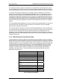
<CHECKSUM> - The checksum is the modulo 256 sum of all preceding message bytes,
excluding the <SYN> character. The checksum determines the presence or absence of errors
within the message. In a message block with the following parameters, the checksum is
computed as shown below in Table 1.
C-2
TM077 – Rev. 4.0
QAM256 Digital Video Modulator and Upconverter
BYTE FIELD
<BYTE COUNT> (Byte 1)
<BYTE COUNT> (Byte 2)
<SOURCEID>
<DESTINATION ID>
<FSN>
<OPCODE> (Byte 1)
<OPCODE> (Byte 2)
<DATA> (Byte 1)
<DATA> (Byte 2)
DATA CONTENT
00h = 00000000b
02h = 00000010b
F0h = 11110000b
2Ah = 00101010b
09h = 00001001b
00h = 00000000b
03h = 00000011b
DFh = 11011111b
FEh = 11111110b
Remote Operations
RUNNING CHECKSUM
00000000b
00000010b
11110010b
00011100b
00100101b
00100101b
00101000b
00000111b
00000101b
Table 1. Checksum Calculation Example
Thus, the checksum is 00000101b, which is 05h or 5 decimal. Alternative methods of calculating
the checksum for the same message frame are:
00h + 02h + F0h + 2Ah + 09h + 00h + 03h + DFh + FEh = 305h.
Since the only concern is the modulo 256 (modulo 100h) equivalent (values that can be
represented by a single 8-bit byte), the checksum is 05h.
For a decimal checksum calculation, the equivalent values for each information field are:
0 + 2 + 240 + 42 + 9 + 0 + 3 + 223 + 254 = 773;
773/256 = 3 with a remainder of 5. This remainder is the checksum for the frame.
5 (decimal) = 05h = 0101b = <CHECKSUM>
C.1.3 Frame Description and Bus Handshaking
In a Monitor and Control environment, every message frame on a control bus port executes as a
packet in a loop beginning with a wait-for-SYN-character mode. The remaining message format
header information is then loaded, either by the M&C computer or by a subordinate piece of
equipment (such as the QAM256) requesting access to the bus. Data is processed in accordance
with the OPCODE, and the checksum for the frame is calculated. If the anticipated checksum
does not match then a checksum error response is returned to the message frame originator. The
entire message frame is discarded and the wait-for-SYN mode goes back into effect. If the
OPCODE resides within a command message, it defines the class of action that denotes an
instruction that is specific to the device type, and is a prefix to the DATA field if data is required. If
the OPCODE resides within a query message packet, then it defines the query code, and can
serve as a prefix to query code DATA.
The Frame Sequence Number (FSN) is included in every message packet and increments
sequentially. When the M & C computer or bus-linked equipment initiates a message, it assigns
the FSN as a tag for error control and handshaking. A different FSN is produced for each new
message from the FSN originator to a specific device on the control bus. If a command packet is
sent and not received at its intended destination, then the packet originator does not receive an
appropriate response message. The original command packet is then re-transmitted with the
same FSN. If the repeated message is received correctly at this point, it is considered a new
message and is executed and acknowledged as such.
If the command packet is received at its intended destination but the response message
(acknowledgment) is lost, then the message originator (usually the M&C computer) re-transmits
the original command packet with the same FSN. The destination device detects the same FSN
TM077 – Rev. 4.0
C-3
Remote Operations
QAM256 Digital Video Modulator and Upconverter
and recognizes that the message is a duplicate, so the associated commands within the packet
are not executed a second time. However, the response packet is again sent back to the source,
as an acknowledgment in order to preclude undesired multiple executions of the same command.
To reiterate, valid equipment responses to a message require the FSN tag in the command
packet. This serves as part of the handshake/acknowledge routine. If a valid response message
is absent, then the command is re-transmitted with the same FSN. For a repeat of the same
command involving iterative processes (such as increasing or decreasing transmit power level of
a QAM256), the FSN is incremented after each message packet. When the FSN value reaches
255, it overflows and begins again at zero. The FSN tag is a powerful tool that assures sequential
information framing, and is especially useful where commands require more than one message
packet.
The full handshake/acknowledgment involves a reversal of source and destination ID codes in the
next message frame, followed by a response code in the <OPCODE> field of the message
packet from the equipment under control.
If a command packet is sent and not received at its intended destination, a timeout condition can
occur because the packet originator does not receive a response message. On receiving devices
slaved to an M & C computer, the timeout delay parameters may be programmed into the
equipment in accordance with site requirements by Radyne Corp. prior to shipment, or altered by
qualified personnel. The FSN handshake routines must account for timeout delays and be able to
introduce them as well.
C.1.4 Global Response Operational Codes
In acknowledgment (response) packets, the operational code <OPCODE> field of the message
packet is set to 0 by the receiving devices when the message intended for the device is evaluated
as valid. The device that receives the valid message then exchanges the <SOURCE ID> with the
<DESTINATION ID>, sets the <OPCODE> to zero in order to indicate that a good message was
received, and returns the packet to the originator. This "GOOD MESSAGE" Opcode is one of
nine global responses. Global response Opcodes are common responses, issued to the M&C
computer or to another device, which can originate from and are interpreted by all Radyne
equipment in the same manner. These are summarized as follows (all Opcode values are
expressed in decimal form):
RESPONSE OPCODE DESCRIPTION
Good Message
Invalid Size
Unknown Error
Invalid Control Mode
Invalid Parameter
Invalid Last Rate Mode
Invalid Symbol Rate (Symbol Rate
Low)
Invalid Symbol Rate (Symbol Rate
High)
Invalid Symbol Rate (Data Rate Low)
Invalid Symbol Rate (Data Rate Low)
Invalid Framing
Invalid Modulation
Invalid Interleaver/Encoder
OPCODE
0000
0001
0002
0003
0004
0005
0006
0007
0008
0009
000A
000B
000D
Table 2. Response OPCODES
C-4
TM077 – Rev. 4.0
QAM256 Digital Video Modulator and Upconverter
Remote Operations
C.1.5 Collision Avoidance
When properly implemented, the physical and logical devices and ID addressing scheme of the
COMMSPEC normally precludes message packet contention on the control bus. The importance
of designating unique IDs for each device during station configuration cannot be overemphasized.
One pitfall, which is often overlooked, concerns multi-drop override IDs. All too often, multiple
devices of the same type are assigned in a direct-linked ("single-thread") configuration accessible
to the M&C computer directly. For example, if two QAM256 Modulators with different addresses
(DESTINATION IDs) are linked to the same control bus at the same hierarchical level, both will
attempt to respond to the M&C computer when the computer generates a multi-drop override ID
of 23. If their actual setup parameters, status, or internal timing differs, they will both attempt to
respond to the override simultaneously with different information or asynchronously in their
respective message packets and response packets, causing a collision on the serial control bus.
To preclude control bus data contention, different IDs must always be assigned to the equipment.
If two or more devices are configured for direct-linked operation, then the M&C computer and all
other devices configured in the same manner must be programmed to inhibit broadcast of the
corresponding multi-drop override ID.
The multi-drop override ID is always accepted by devices of the same type on a common control
bus, independent of the actual DESTINATION ID. These override IDs with the exception of
“BROADCAST” are responded to by all directly linked devices of the same type causing
contention on the bus. The “BROADCAST” ID, on the other hand, is accepted by all equipment
but none of them returns a response packet to the remote M&C.
The following multi-drop override IDs are device-type specific, with the exception of
"BROADCAST.” These are summarized below with ID values expressed in decimal notation:
DIRECTLY-ADDRESSED EQUIPMENT
Broadcast (all directly-linked devices)
DMD-3000/4000, 4500 or 5000 Mod Section,
DMD15
DMD-3000/4000, 4500 or 5000 Demod Section,
DMD15
MULTI-DROP OVERRIDE ID
00
01
RCU-340 1:1 Switch
RCS-780 1:N Switch
RMUX-340 Cross-Connect Multiplexer
CDS-780 Clock Distribution System
SOM-340 Second Order Multiplexer
DMD-4500/5000 Modulator Section
DMD-4500/5000 Demodulator Section
RCU-5000 M:N Switch
DMD15 Modulator
DMD15 Demodulator
DMD15 Modem
DM45 Video Modulator
QAM256 Modulator
Reserved for future equipment types
02
03
04
05
06
07
08
09
10
20
21
22
23
32
24 – 31
Table 3. Broadcast ID’s
Note that multi-drop override ID 01 can be used interchangeably to broadcast a message to a
DMD-3000/4000 modem, a DMD-4500/5000, a DMD15 modem, or a DM45. Radyne Corp.
recommends that experienced programmers issue the multi-drop override IDs only during system
configuration as a bus test tool, and that they not be included in run-time software. It is also
TM077 – Rev. 4.0
C-5
Remote Operations
QAM256 Digital Video Modulator and Upconverter
advantageous to consider the use of multiple bus systems where warranted by a moderate to
large equipment complement.
Therefore, if a DMD15 Modulator is queried for its equipment type identifier, it will return a "20"
and DMD15 Demodulator will return a "21". A DMD15 Modem will also return a "22". A DM45
Video Modulator will return a “23.”
C.1.6 Software Compatibility
The COMMSPEC, operating in conjunction within the RLLP shell, provides for full forward and
backward software compatibility independent of the software version in use. New features are
appended to the end of the DATA field without OPCODE changes. Older software simply
discards the data as extraneous information without functional impairment for backward
compatibility.
If new device-resident or M&C software receives a message related to an old software version,
new information and processes are not damaged or affected by the omission of data.
The implementation of forward and backward software compatibility often, but not always,
requires the addition of new Opcodes. Each new function requires a new Opcode assignment if
forward and backward compatibility cannot be attained by other means.
C.1.7 Flow Control and Task Processing
The original packet sender (the M&C computer) relies on accurate timeout information with
regard to each piece of equipment under its control. This provides for efficient bus communication
without unnecessary handshake overhead timing. One critical value is designated the InterFrame Space (FS). The Inter-Frame Space provides a period of time in which the packet receiver
and medium (control bus and M&C computer interface) fully recover from the packet
transmission/reception process and the receiver is ready to accept a new message. The
programmed value of the Inter-Frame Space should be greater than the sum of the "turnaround
time" and the round-trip (sender/receiver/bus) propagation time, including handshake overhead.
The term "turnaround time" refers to the amount of time required for a receiver to be re-enabled
and ready to receive a packet after having just received a packet. In flow control programming,
the Inter-Frame Space may be determined empirically in accord with the system configuration or
calculated based on established maximum equipment task processing times.
Each piece of supported equipment on the control bus executes a Radyne Link Level Task
(RLLT) in accordance with its internal hardware and fixed program structure. In a flow control
example, the RLLT issues an internal "message in" system call to invoke an I/O wait condition
that persists until the task receives a command from the M & C computer. The RLLT has the
option of setting a timeout on the incoming message. Thus, if the equipment does not receive an
information/command packet within a given period, the associated RLLT exits the I/O wait state
and takes appropriate action.
Radyne equipment is logically linked to the control bus via an Internal Input / Output Processing
Task (IOPT) to handle frame sequencing, error checking, and handshaking. The IOPT is
essentially a link between the equipment RLLT and the control bus. Each time the M&C computer
sends a message packet; the IOPT receives the message and performs error checking. If errors
are absent, the IOPT passes the message to the equipment's RLLT. If the IOPT detects errors, it
appends error messages to the packet. Whenever an error occurs, the IOPT notes it and discards
the message; but it keeps track of the incoming packet. Once the packet is complete, the IOPT
conveys the appropriate message to the RLLT and invokes an I/O wait state (wait for next
<SYNC> character).
C-6
TM077 – Rev. 4.0
QAM256 Digital Video Modulator and Upconverter
Remote Operations
If the RLLT receives the packetized message from the sender before it times out, it checks
for any error messages appended by the IOPT. In the absence of errors, the RLLT processes the
received command sent via the transmitted packet and issues a "message out" system call to
ultimately acknowledge the received packet. This call generates the response packet conveyed to
the sender. If the IOPT sensed errors in the received packet and an RLLT timeout has not
occurred, the RLLT causes the equipment to issue the appropriate error message(s) in the
pending equipment response frame.
To maintain frame synchronization, the IOPT keeps track of error-laden packets and packets
intended for other equipment for the duration of each received packet. Once the packet is
complete, the IOPT invokes an I/O wait state and searches for the next <SYNC> character.
C.1.8 RLLP Summary
The RLLP is a simple send-and-wait protocol that automatically re-transmits a packet whenever
an error is detected, or when an acknowledgment (response) packet is absent. During
transmission, the protocol wrapper surrounds the actual data to form information packets. Each
transmitted packet is subject to time out and frame sequence control parameters, after which the
packet sender waits for the receiver to convey its response. Once a receiver verifies that a packet
sent to it is in the correct sequence relative to the previously received packet, it computes a local
checksum on all information within the packet excluding the <SYN> character and the
<CHECKSUM> fields. If this checksum matches the packet <CHECKSUM>, the receiver
processes the packet and responds to the packet sender with a valid response (acknowledgment)
packet. If the checksum values do not match, the receiver replies with a negative
acknowledgment (NAK) in its response frame.
The response packet is therefore either an acknowledgment that the message was received
correctly, or some form of a packetized NAK frame. If the sender receives a valid
acknowledgment (response) packet from the receiver, the <FSN> increments and the next packet
is transmitted as required by the sender. However, if a NAK response packet is returned the
sender re-transmits the original information packet with the same embedded <FSN>.
If an acknowledgment (response) packet or a NAK packet is lost, corrupted, or not issued due to
an error and is thereby not returned to the sender, the sender re-transmits the original information
packet; but with the same <FSN>. When the intended receiver detects a duplicate packet, the
packet is acknowledged with a response packet and internally discarded to preclude undesired
repetitive executions. If the M&C computer sends a command packet and the corresponding
response packet is lost due to a system or internal error, the computer times out and re-transmits
the same command packet with the same <FSN> to the same receiver and waits once again for
an acknowledgment or a NAK packet.
To reiterate, the format of the message block is shown in Table 4, Link Level Protocol
Message Block
Sync
Count
Source
Address
Destinati
on
Address
FSN
Opcod
e
Data
Bytes
Checksu
m
Table 4. Link Level Protocol Message Block
RLLP Remote Communications Examples
Example #1
Query Common Control Mode
Example Parameters:
TM077 – Rev. 4.0
C-7
Remote Operations
QAM256 Digital Video Modulator and Upconverter
SYNC Byte = 16h (Always.)
Data Count = 00 00h
Source Address = FFh
Destination Address = 20h = 32 decimal
Frame Sequence Number = 01h
Opcode = 20 01h
Checksum = 41h
Transmit Packet:
16 00 00 FF 20 01 20 01 41
Response Packet:
16 00 01 20 FF 01 00 00 02 23
Error Response = 00 00 (Command OK)
Control Mode = 02. (Computer)
Example #2
Query Common Control Mode with BAD Opcode
Example Parameters:
SYNC Byte = 16h (Always.)
Data Count = 00 00h
Source Address = FFh
Destination Address = 20h = 32 decimal
Frame Sequence Number = 01h
Opcode = 20 0Fh (BAD Opcode)
Checksum = 4Fh
Transmit Packet:
16 00 00 FF 20 01 20 0F 4F
Response Packet:
16 00 00 20 FF 01 00 02 22
Error Response = 00 02
Example #3
Command Mod Data rate
Example Parameters:
SYNC Byte = 16h (Always.)
Data Count = 00 04h
Source Address = FFh
Destination Address = 2Ch = 44 decimal
Frame Sequence Number = 01h
Opcode = 22 41h
Data = 00 7A 12 00h
Checksum = 1Fh
Transmit Packet:
16 00 04 FF 2C 01 22 41 00 7A 12 00 1F
Response Packet:
16 00 00 2C FF 01 00 00 2C
Error Response = 00 00 (Command OK)
C-8
TM077 – Rev. 4.0
QAM256 Digital Video Modulator and Upconverter
Example #4
Remote Operations
Command Mod TX Enable. (On)
Example Parameters:
SYNC Byte = 16h (Always.)
Data Count = 00 01h
Source Address = FFh
Destination Address = 20h = 32 decimal
Frame Sequence Number = 7Fh
Opcode = 22 54h
Data = 01h (01h = On)
Checksum = 16h
Transmit Packet:
16 00 01 FF 20 7F 22 54 01 16
Response Packet:
16 00 00 20 FF 7F 00 00 9E
Error Response = 00 00 (Command OK)
C.2
Remote Port Modes of Operation:
The RLLP Remote Port Packet structure is as follows:
<SYNC>
<BYTE COUNT>
<SOURCE ID>
<DESTINATION ID>
<F.S.N.>
<OPCODE>
<…DATA…>
<CHECKSUM>
= Message format header character that defines the beginning of a
message. The <SYNC> character value is always 0x16, (1 byte).
= Number of bytes in the <DATA> field, (2 bytes).
= Identifies the address of the equipment from where the message
= Identifies the address of the equipment where the message is to be
sent, (1 byte).
= Frame sequence number ensures correct packet acknowledgment and
data transfers, (1 byte).
= This byte identifies the message type associated with the information
data. The equipment processes the data according to the value in this
field. Return error codes and acknowledgment are also included in this
field, (2 bytes).
= Information data. The number of data bytes in this field is indicated by
the <BYTE COUNT> value.
= The modulo 256 sum of all preceding message bytes excluding the
<SYNC> character, (1 byte).
QAM256 Common Query Set:
Query
Query Common ID
Query Common Control Mode
Query Common Version
Query Common Firmware
Query Common Time
Query Common Date
Query Common Time & Date
Query Common Alarms
Query Common Alarm Mask
TM077 – Rev. 4.0
Opcode
<2000h>
<2001h>
<2002h>
<2003h>
<2004h>
<2005h>
<2006h>
<2007h>
<2008h>
C-9
Remote Operations
QAM256 Digital Video Modulator and Upconverter
Query Common Last Rate
Control
<2009h>
QAM256 Common Command Set:
Command
Command Common Control Mode
Command Common Time
Command Common Date
Command Common Time & Date
Command Clear Common Alarms
Command Common Alarm Mask
Command Common Last Rate
Control
Opcode
<2201h>
<2204h>
<2205h>
<2206h>
<2207h>
<2208h>
<2209h>
QAM256 Modulator Command Set:
Query
Query Modulator Frequency
Query Modulator Data rate
Query Modulator Symbol rate
Query Modulator Last rate
control
Query Modulator Modulation
Query Modulator Spectrum
Query Modulator Framing
Query Modulator Interleaver /
Encoder
Query Modulator Roll off
Query Modulator Interface
Type
Query Modulator Data Polarity
Query Modulator Clock
Polarity
Query Modulator Alarms
Query Modulator Alarm Mask
Query Modulator PRBS
Query Modulator BB
Loopback
Query Modulator TX Power
Query Modulator TX Enable
Query Modulator TX Carrier
Query Modulator Channel
Table
Query Modulator Channel
Opcode
<2040h>
<2041h>
<2042h>
<2043h>
<2044h>
<2045h>
<2046h>
<2047h>
<2049h>
<204Ah>
<204Bh>
<204Ch>
<204Dh>
<204Eh>
<204Fh>
<2051h>
<2053h>
<2054h>
<2055h>
<2060h>
<2061h>
QAM256 Modulator Command Set:
Command
Command Modulator Frequency
Command Modulator Data rate
Command Modulator Symbol rate
Command Modulator Modulation
Command Modulator Spectrum
C-10
Opcode
<2240h>
<2241h>
<2242h>
<2244h>
<2245h>
TM077 – Rev. 4.0
QAM256 Digital Video Modulator and Upconverter
Command Modulator Framing
Command Modulator Interleaver
Command Modulator Roll off
Command Modulator Interface
Type
Command Modulator Data
Polarity
Command Modulator Clock
Polarity
Command Modulator Clear
Alarms
Command Modulator Alarm Mask
Command Modulator PRBS
Command Modulator BB
Loopback
Command Modulator TX Power
Command Modulator TX Enable
Command Modulator TX Carrier
Command Modulator Channel
Table
Command Modulator Channel
Remote Operations
<2246h>
<2247h>
<2249h>
<224Ah>
<224Bh>
<224Ch>
<224Dh>
<224Eh>
<224Fh>
<2251h>
<2253h>
<2254h>
<2255h>
<2260h>
<2261h>
Common Query Opcodes
Opcode: <2000h>
Query response:
<1>
Modem ID
Query a modulator’s identification
(QAM256 modulator’s ID = 32)
Opcode: <2001h>
Query a modulator’s control mode
Query response:
<1>
Modem control mode (0=Front Panel, 1=Terminal, 2=Computer, 3 = Ethernet)
Opcode: <2002h>
Query response:
<1>
Version
Query a modulator’s Firmware version.
Opcode: <2003h>
Query response:
<16> Firmware
Query a modulator’s Firmware information.
Opcode: <2004h>
Query response:
<1>
Hour
<1>
Minute
<1>
Second
Query a modulator’s time.
Opcode: <2005h>
Query response:
<1>
Year
<1>
Month
<1>
Day
Query a modulator’s date.
Opcode: <2006h>
Query response:
Query a modulator’s time and date combined.
TM077 – Rev. 4.0
(implied decimal point)
(8 bytes for firmware part number.)
(8 bytes for release date.)
(0 through 23)
(0 through 59)
(0 through 59)
(0 through 99)
(0 through 11)
(0 through 30)
C-11
Remote Operations
<1>
<1>
<1>
<1>
<1>
<1>
Year
Month
Day
Hour
Minute
Second
QAM256 Digital Video Modulator and Upconverter
(0 through 99)
(0 through 11)
(0 through 30)
(0 through 23)
(0 through 59)
(0 through 59)
Opcode: <2007h>
Query a modulator's common alarms
Query response:
<1>
Common Alarm1
(Bit 0 = M&C Hardware Fault)
(Bit 1 = Interface. Hardware Fault)
(Bit 2 = Spare)
(Bit 3 = Spare)
(Bit 4 = Spare)
(Bit 5 = Spare)
(Bit 6 = Spare)
(Bit 7 = Spare)
<1>
Common Alarm2
(Bit 0 = Spare)
(Bit 1 = Spare)
(Bit 2 = Spare)
(Bit 3 = Spare)
(Bit 4 = Spare)
(Bit 5 = Spare)
(Bit 6 = Spare)
(Bit 7 = Spare)
<1>
LatchedComAlarm1
(Bit 0 = M&C Hardware Fault)
(Bit 1 = Interface. Hardware Fault)
(Bit 2 = Spare)
(Bit 3 = Spare)
(Bit 4 = Spare)
(Bit 5 = Spare)
(Bit 6 = Spare)
(Bit 7 = Spare)
<1>
LatchedComAlarm2
(Bit 0 = Spare)
(Bit 1 = Spare)
(Bit 2 = Spare)
(Bit 3 = Spare)
(Bit 4 = Spare)
(Bit 5 = Spare)
(Bit 6 = Spare)
(Bit 7 = Spare)
Opcode: <2008h>
Query a modulator's common alarms mask
Query response:
<1>
Common Alarm1
(Bit 0 = M&C Hardware Fault)
(Bit 1 = Interface. Hardware Fault)
(Bit 2 = Spare)
(Bit 3 = Spare)
(Bit 4 = Spare)
(Bit 5 = Spare)
(Bit 6 = Spare)
(Bit 7 = Spare)
(0 = mask, 1 = allow)
<1>
Common Alarm2
(Bit 0 = Spare)
(Bit 1 = Spare)
(Bit 2 = Spare)
C-12
TM077 – Rev. 4.0
QAM256 Digital Video Modulator and Upconverter
Remote Operations
(Bit 3 = Spare)
(Bit 4 = Spare)
(Bit 5 = Spare)
(Bit 6 = Spare)
(Bit 7 = Spare)
(0 = mask, 1 = allow)
Opcode: <2009h>
Query a modulator’s Last Rate Control.
Query response:
<1>
Last Rate Control
(0=Symbol, 1=Data, 2=Auto)
Common Command Opcodes
Opcode: <2201h>
Set Common control mode
<1>
Modem control mode (0=Front Panel, 1=Terminal, 2=Computer, 3 = Ethernet)
Opcode: <2204h>
<1>
Hour
<1>
Minute
<1>
Second
Set Common time
(0 through 23)
(0 through 59)
(0 through 59)
Opcode: <2205h>
<1>
Year
<1>
Month
<1>
Day
Set Common date
(0 through 99)
(0 through 11)
(0 through 30)
Opcode: <2206h>
<1>
Year
<1>
Month
<1>
Day
<1>
Hour
<1>
Minute
<1>
Second
Set Common time and date
(0 through 99)
(0 through 11)
(0 through 30)
(0 through 23)
(0 through 59)
(0 through 59)
Opcode: <2207h>
<0>
Clear Alarms
Clear Common Alarms.
(no parameters)
Opcode: <2208h>
Command Mask Alarms.
<1>
Common Alarm1
(Bit 0 = M&C Hardware Fault)
(Bit 1 = Interface. Hardware Fault)
(Bit 2 = Spare)
(Bit 3 = Spare)
(Bit 4 = Spare)
(Bit 5 = Spare)
(Bit 6 = Spare)
(Bit 7 = Spare)
(0 = mask, 1 = allow)
<1>
Common Alarm2
(Bit 0 = Spare)
(Bit 1 = Spare)
(Bit 2 = Spare)
(Bit 3 = Spare)
(Bit 4 = Spare)
(Bit 5 = Spare)
(Bit 6 = Spare)
(Bit 7 = Spare)
(0 = mask, 1 = allow)
TM077 – Rev. 4.0
C-13
Remote Operations
QAM256 Digital Video Modulator and Upconverter
Opcode: <2209h>
Set Common Last Rate Control.
<1>
Last Rate Control
(0=Symbol, 1=Data, 2=Auto)
Modulator Query Opcodes
Opcode: <2040h>
Query response:
<4>
Frequency
Query a modulator's frequency
Opcode: <2041h>
Query response:
<4>
Data rate
Query a modulator's data rate
Opcode: <2042h>
Query response:
<4>
Symbol rate
Query a modulator's symbol rate
(Binary value, 1 Hz steps)
(Without cable Upconverter the range = 43 MHz to 44 MHz, or
Optional 35 MHz to 37 MHz)
(With cable Upconverter the range = 50 MHz to 862 MHz)
(Binary value, 1bps steps)
(Binary value, 1sps steps)
Opcode: <2043h>
Query a modulator's last rate control.
Query response:
<1>
Last Rate Control
(0 = Symbol, 1 = Data)
Opcode: <2044h>
Query response:
<1>
Modulation
Query a modulator's modulation.
Opcode: <2045h>
Query response:
<1>
Spectrum
Query a modulator's spectrum.
Opcode: <2046h>
Query response:
<1>
Framing
Query a modulator's framing.
(0=4 QAM, 1=16 QAM, 2=32 QAM, 3=64 QAM, 4=128 QAM,
5=256 QAM)
(0=Normal, 1=Inverted)
(0=MPEG 187, 1=MPEG 188, 2=MPEG 204, 3=Data)
Opcode: <2047h>
Query a modulator's interleave and Encoder.
Query response:
<1>
Interleaver/Encoder
(For Annex-A)
(0 = 1,204, 1 = 2,102, 2 = 3,68, 3 = 4,51, 4 = 6,34, 5 = 12,17, 6 =
17,12, 7 = 34,6, 8 = 51,4, 9 = 68,3, 10 = 102,2, 11 = 204,1)
(For Annex-B)
(12 = 128,1, 13 = 128,2, 14 = 64,2, 15 = 128,3, 16 = 32,4, 17 =
128,4, 18 = 16,8, 19 = 128,5, 20 = 8,16, 21 = 128,6, 22 = 4,32,
23 = 128,7, 24 = 2,64, 25 = 128,8, 26 = 1,128)
Opcode: <2049h>
Query response:
<1>
Roll off
Query a modulator's roll off.
(0=0.12, 1=0.15, 2=0.18)
Opcode: <204Ah>
Query a modulator's interface type.
Query response:
<1>
Interface Type
(0 = STS1, 1 = G.703-E3, 2 = G.703-T3, 3 = Normal ASI, 4 =
Advanced ASI, 5 = DVB Parallel, 6 = M2P Parallel, 7 = ECL, 8 =
C-14
TM077 – Rev. 4.0
QAM256 Digital Video Modulator and Upconverter
Remote Operations
HSSI)
Opcode: <204Bh>
Query response:
<1>
Data Polarity
Query a modulator's data polarity
Opcode: <204Ch>
Query response:
<1>
Clock Polarity
Query a modulator's clock polarity
Opcode: <204Dh>
Query response:
<1>
Major Alarm1
Query a modulator's alarms
(0=Normal, 1=Inverted)
(0=Normal, 1=Inverted)
<1>
Major Alarm2
<1>
Latched Major Alarm1
<1>
Latched Major Alarm2
<1>
Minor Alarm1
C
<1>
Minor Alarm2
TM077 – Rev. 4.0
(Bit 0 = Mod Hardware)
(Bit 1 = Tx Synthesizer lock)
(Bit 2 = Data PLL lock)
(Bit 3 = Frame lock)
(Bit 4 = Mod1 lock)
(Bit 5 = Mod2 lock)
(Bit 6 = Mod3 lock)
(Bit 7 = Spare)
(Bit 0 = RX up synthesizer lock)
(Bit 1 = RX down synthesizer lock)
(Bit 2 = RF temperature Detect)
(Bit 3 = RF CPLD (hardware))
(Bit 4 = Spare)
(Bit 5 = Spare)
(Bit 6 = Spare)
(Bit 7 = Spare)
(Bit 0 = Clock Activity Fault)
(Bit 1 = Data Activity Fault)
(Bit 2 = FIFO Fault)
(Bit 3 = Mod Clock Activity Fault)
(Bit 4 = Spare)
(Bit 5 = Spare)
(Bit 6 = Spare)
(Bit 7 = Spare)
(Bit 0 = Spare)
(Bit 1 = Spare)
(Bit 2 = Spare)
(Bit 3 = Spare)
C-15
Remote Operations
QAM256 Digital Video Modulator and Upconverter
<1>
Latched Minor Alarm1
<1>
Latched Minor Alarm2
Opcode: <204Eh>
Query response:
<1>
Major Alarm1
<1>
Major Alarm2
<1>
Minor Alarm1
<1>
Minor Alarm2
C-16
(Bit 4 = Spare)
(Bit 5 = Spare)
(Bit 6 = Spare)
(Bit 0 = Clock Activity Fault)
(Bit 1 = Data Activity Fault)
(Bit 2 = FIFO Fault)
(Bit 3 = Mod Clock Activity Fault)
(Bit 4 = Spare)
(Bit 5 = Spare)
(Bit 6 = Spare)
(Bit 7 = Spare)
(Bit 0 = Spare)
(Bit 1 = Spare)
(Bit 2 = Spare)
(Bit 3 = Spare)
(Bit 4 = Spare)
(Bit 5 = Spare)
(Bit 6 = Spare)
(Bit 7 = Spare)
Query a modulator’s alarm Mask.
(Bit 0 = Mod Hardware)
(Bit 1 = Tx Synthesizer lock)
(Bit 2 = Data PLL lock)
(Bit 3 = Frame lock)
(Bit 4 = Mod1 lock)
(Bit 5 = Mod2 lock)
(Bit 6 = Mod3 lock)
(Bit 7 = Spare)
(0 = mask, 1 = allow)
(Bit 0 = RX up synthesizer lock)
(Bit 1 = RX down synthesizer lock)
(Bit 2 = RF temperature Detect)
(Bit 3 = RF CPLD (hardware))
(Bit 4 = Spare)
(Bit 5 = Spare)
(Bit 6 = Spare)
(Bit 7 = Spare)
(0 = mask, 1 = allow)
(Bit 0 = Clock Activity Fault)
(Bit 1 = Data Activity Fault)
(Bit 2 = FIFO Fault)
(Bit 3 = Mod Clock Activity Fault)
(Bit 4 = Spare)
(Bit 5 = Spare)
(Bit 6 = Spare)
(Bit 7 = Spare)
(0 = mask, 1 = allow)
(Bit 0 = Spare)
(Bit 1 = Spare)
(Bit 2 = Spare)
(Bit 3 = Spare)
(Bit 4 = Spare)
(Bit 5 = Spare)
(Bit 6 = Spare)
TM077 – Rev. 4.0
QAM256 Digital Video Modulator and Upconverter
Remote Operations
(0 = mask, 1 = allow)
Opcode: <204Fh>
Query response:
<1>
PRBS
Query a modulator's PRBS (test pattern)
Opcode: <2051h>
Query response:
<1>
BB Loopback
Query a modulator's Base Band Loopback
Opcode: <2053h>
Query response:
<4>
Tx Power
Query a modulator's output power level
(0 = Normal, 1 = PRBS23, 2 = PRBS23M, 3 = PRBS15, 4 =
PRBS15M)
(0 = Normal, 1 = Loopback)
Without cable Upconverter, value is in dBm.
(Signed value. +00 to -250 (+0.0 to -25.0 dBm)
(Implied decimal point)
Ex: +0.0dbm, data returned = 00 00 00 00 = 00 decimal =
+0.0dbm
Ex: -25.0dbm, data returned = FF FF FF 06 = 100000000 –
FFFFFF06 = FAh = 250 = -25.0 dBm
With cable Upconverter, value is in dBv.
(Signed value. +450 to +600 (+45.0 to +60.0 dBv)
(Implied decimal point)
Opcode: <2054h>
Query response:
<1>
TX Enable
Query a modulator's carrier control
Opcode: <2055h>
Query response:
<1>
TX Carrier
Query a modulator's carrier test
(0=Off, 1=On)
(0=Normal, 1=CW)
Opcode: <2060h>
Query a modulator's channel table
Query response:
<1>
Channel Table
(0 = EIA STD, 1 = EIA HRC, 2 =EIA IRC, 3 = Trad STD, 4 = Trad
HRC, 5 = Trad IRC)
Opcode: <2061h>
Query response:
<1>
Channel
Query a modulator's channel
(See channel entry tables at end of protocol)
Modulator Command Opcodes
Opcode: <2240h>
<4>
Frequency
Command a modulator's frequency
(Binary value, 1 Hz steps)
(Without cable Upconverter the range = 43 MHz to 44 MHz, or
Optional 35 MHz to 37 MHz)
(With cable Upconverter the range = 50 MHz to 862 MHz)
(This command will cause the carrier to turn off)
Opcode: <2241h>
<4>
Data rate
Command a modulator's data rate
(Binary value, 1bps steps)
(This command will cause the carrier to turn off)
Opcode: <2242h>
Command a modulator's symbol rate
TM077 – Rev. 4.0
C-17
Remote Operations
<4>
Symbol rate
Opcode: <2244h>
<1>
Modulation
QAM256 Digital Video Modulator and Upconverter
(Binary value, 1sps steps)
(This command will cause the carrier to turn off)
Command a modulator's modulation.
(0=4 QAM, 1=16 QAM, 2=32 QAM, 3=64 QAM, 4=128 QAM,
5=256 QAM)
Opcode: <2245h>
<1>
Spectrum
Command a modulator's spectrum.
(0=Normal, 1=Inverted)
Opcode: <2246h>
<1>
Framing
Command a modulator's framing.
(0=MPEG 187, 1=MPEG 188, 2=MPEG 204, 3=Data)
Opcode: <2247h>
Command a modulator's Interleaver and Encoder.
<1>
Interleaver/Encoder
(For Annex-A)
(0 = 1,204, 1 = 2,102, 2 = 3,68, 3 = 4,51, 4 = 6,34, 5 = 12,17, 6 =
17,12, 7 = 34,6, 8 = 51,4, 9 = 68,3, 10 = 102,2, 11 = 204,1)
(For Annex-B)
(12 = 128,1, 13 = 128,2, 14 = 64,2, 15 = 128,3, 16 = 32,4, 17 =
128,4, 18 = 16,8, 19 = 128,5, 20 = 8,16, 21 = 128,6, 22 = 4,32,
23 = 128,7, 24 = 2,64, 25 = 128,8, 26 = 1,128)
Opcode: <2249h>
<1>
Roll off
Command a modulator's roll off.
(0=0.12, 1=0.15, 2=0.18)
Opcode: <224Ah>
Command a modulator's interface type
<1>
Interface Type
(0 = STS1, 1 = G.703-E3, 2 = G.703-T3, 3 = Normal ASI, 4 =
Advanced ASI, 5 = DVB Parallel, 6 = M2P Parallel, 7 = ECL, 8 =
HSSI)
Opcode: <224Bh>
<1>
Data Polarity
Command a modulator's data polarity
(0=Normal, 1=Inverted)
Opcode: <224Ch>
<1>
Clock Polarity
Command a modulator's clock polarity
(0=Normal, 1=Inverted)
Opcode: <224Dh>
<0>
Clear Alarms
Clear a modulator's Alarms.
(no parameters
Opcode: <224Eh>
<1>
Major Alarm1
Mask a modulators Alarms.
(Bit 0 = Mod Hardware)
(Bit 1 = Tx Synthesizer lock)
(Bit 2 = Data PLL lock)
(Bit 3 = Frame lock)
(Bit 4 = Mod1 lock)
(Bit 5 = Mod2 lock)
(Bit 6 = Mod3 lock)
(Bit 7 = Spare)
(0 = mask, 1 = allow)
(Bit 0 = RF up synthesizer lock)
(Bit 1 = RF down synthesizer lock)
(Bit 2 = RF temperature Detect)
(Bit 3 = RF CPLD (hardware))
(Bit 4 = Spare)
(Bit 5 = Spare)
<1>
C-18
Major Alarm2
TM077 – Rev. 4.0
QAM256 Digital Video Modulator and Upconverter
<1>
Minor Alarm1
<1>
Minor Alarm2
Remote Operations
(Bit 6 = Spare)
(Bit 7 = Spare)
(0 = mask, 1 = allow)
(Bit 0 = Clock Activity Fault)
(Bit 1 = Data Activity Fault)
(Bit 2 = FIFO Fault)
(Bit 3 = Mod Clock Activity Fault)
(Bit 4 = Spare)
(Bit 5 = Spare)
(Bit 6 = Spare)
(Bit 7 = Spare)
(0 = mask, 1 = allow)
(Bit 0 = Spare)
(Bit 1 = Spare)
(Bit 2 = Spare)
(Bit 3 = Spare)
(Bit 4 = Spare)
(Bit 5 = Spare)
(Bit 6 = Spare)
(0 = mask, 1 = allow)
Opcode: <224Fh>
<1>
PRBS
Command a modulator's PRBS (test pattern)
(0 = Normal, 1 = PRBS23, 2 = PRBS23M, 3 = PRBS15, 4 =
PRBS15M)
Opcode: <2251h>
<1>
BB Loopback
Command a modulator's Base Band Loopback
(0 = Normal, 1 = Loopback)
Opcode: <2253h>
<4>
Tx Power
Command a modulators output power level
Without cable Upconverter, value is in dBm.
(Signed value. +00 to -250 (+0.0 to -25.0 dBm)
(Implied decimal point)
Ex: +0.0 dBm, data returned = 00 00 00 00 = 00 decimal = +0.0
dBm
Ex: -25.0 dBm, data returned = FF FF FF 06 = 100000000 –
FFFFFF06 = FAh = 250 = -25.0 dBm
With cable Upconverter, value is in dBv.
(Signed value +450 to +600 (+45.0 to +60.0 dBv)
(Implied decimal point)
Opcode: <2254h>
<1>
TX Enable
Command a modulator's carrier control
(0=Off, 1=On)
Opcode: <2255h>
<1>
TX Carrier
Command a modulator's carrier test
(0=Normal, 1=CW)
Opcode: <2260h>
Command a modulator's channel table
<1>
Channel Table
(0 = EIA STD, 1 = EIA HRC, 2 =EIA IRC, 3 = Trad STD, 4 = Trad
HRC, 5 = Trad IRC)
Opcode: <2261h>
<1>
Channel
Command a modulator's channel
(See channel entry tables at end of protocol)
The following information is applicable to the QAM256 Cable Upconverter:
TM077 – Rev. 4.0
C-19
Remote Operations
QAM256 Digital Video Modulator and Upconverter
Following are the US channel entries:
US
Channel Freq. in
EIA
MHz
STD
Entry
0
Custom Custom
1
"2"
55.25
2
"3"
61.25
3
"4"
67.25
4
"1"
Custom
5
"5"
77.25
6
"6"
83.25
7
"95"
91.25
8
"96"
97.25
9
"97"
103.25
10
"98"
109.25
11
"99"
115.25
12
"14"
121.25
13
"15"
127.25
14
"16"
133.25
15
"17"
139.25
16
"18"
145.25
17
"19"
151.25
18
"20"
157.25
19
"21"
163.25
20
"22"
169.25
21
"7"
175.25
22
"8"
181.25
23
"9"
187.25
24
"10"
193.25
25
"11"
199.25
26
"12"
205.25
27
"13"
211.25
28
"23"
217.25
29
"24"
223.25
30
"25"
229.25
31
"26"
235.25
32
"27"
241.25
33
"28"
247.25
34
"29"
253.25
35
"30"
259.25
36
"31"
265.25
37
"32"
271.25
38
"33"
277.25
39
"34"
283.25
40
"35"
289.25
41
"36"
295.25
42
"37"
301.25
43
"38"
307.25
44
"39"
313.25
45
"40"
319.25
46
"41"
325.25
47
"42"
331.25
48
"43"
337.25
US
EIA
STD
Entry
59
60
61
62
63
64
65
66
67
68
69
70
71
72
73
74
75
76
77
78
79
80
81
82
83
84
85
86
87
88
89
90
91
92
93
94
95
96
97
98
99
100
101
102
103
104
105
106
107
C-20
Channel
Freq. in
MHz
"54"
"55"
"56"
"57"
"58"
"59"
"60"
"61"
"62"
"63"
"64"
"65"
"66"
"67"
"68"
"69"
"70"
"71"
"72"
"73"
"74"
"75"
"76"
"77"
"78"
"79"
"80"
"81"
"82"
"83"
"84"
"85"
"86"
"87"
"88"
"89"
"90"
"91"
"92"
"93"
"94"
"100"
"101"
"102"
"103"
"104"
"105"
"106"
"107"
403.25
409.25
415.25
421.25
427.25
433.25
439.25
445.25
451.25
457.25
463.25
469.25
475.25
481.25
487.25
493.25
499.25
505.25
511.25
517.25
523.25
529.25
535.25
541.25
547.25
553.25
559.25
565.25
571.25
577.25
583.25
589.25
595.25
601.25
607.25
613.25
619.25
625.25
631.25
637.25
643.25
649.25
655.25
661.25
667.25
673.25
679.25
685.25
691.25
TM077 – Rev. 4.0
QAM256 Digital Video Modulator and Upconverter
Remote Operations
49
50
51
52
53
54
55
56
57
58
"44"
"45"
"46"
"47"
"48"
"49"
"50"
"51"
"52"
"53"
343.25
349.25
355.25
361.25
367.25
373.25
379.25
385.25
391.25
397.25
108
109
110
111
112
113
114
115
116
"108"
"109"
"110"
"111"
"112"
"113"
"114"
"115"
"116"
697.25
703.25
709.25
715.25
721.25
727.25
733.25
739.25
745.25
US
EIA
HRC
Entry
0
1
2
3
4
5
6
7
8
9
10
11
12
13
14
15
16
17
18
19
20
21
22
23
24
25
26
27
28
29
30
31
32
33
34
35
36
37
38
Channel
Freq. in
MHz
Channel
Freq. in
MHz
Custom
"2"
"3"
"4"
"1"
"5"
"6"
"95"
"96"
"97"
"98"
"99"
"14"
"15"
"16"
"17"
"18"
"19"
"20"
"21"
"22"
"7"
"8"
"9"
"10"
"11"
"12"
"13"
"23"
"24"
"25"
"26"
"27"
"28"
"29"
"30"
"31"
"32"
"33"
Custom
54.00
60.00
66.00
72.00
78.00
84.00
90.00
96.00
102.00
108.00
114.00
120.00
126.00
132.00
138.00
144.00
150.00
156.00
162.00
168.00
174.00
180.00
186.00
192.00
198.00
204.00
210.00
216.00
222.00
228.00
234.00
240.00
246.00
252.00
258.00
264.00
270.00
276.00
US
EIA
HRC
Entry
59
60
61
62
63
64
65
66
67
68
69
70
71
72
73
74
75
76
77
78
79
80
81
82
83
84
85
86
87
88
89
90
91
92
93
94
95
96
97
"54"
"55"
"56"
"57"
"58"
"59"
"60"
"61"
"62"
"63"
"64"
"65"
"66"
"67"
"68"
"69"
"70"
"71"
"72"
"73"
"74"
"75"
"76"
"77"
"78"
"79"
"80"
"81"
"82"
"83"
"84"
"85"
"86"
"87"
"88"
"89"
"90"
"91"
"92"
402.00
408.00
414.00
420.00
426.00
432.00
438.00
444.00
450.00
456.00
462.00
468.00
474.00
480.00
486.00
492.00
498.00
504.00
510.00
516.00
522.00
528.00
534.00
540.00
546.00
552.00
558.00
564.00
570.00
576.00
582.00
588.00
594.00
600.00
606.00
612.00
618.00
624.00
630.00
TM077 – Rev. 4.0
C-21
Remote Operations
C-22
QAM256 Digital Video Modulator and Upconverter
39
40
41
42
43
44
45
46
47
48
49
50
51
52
53
54
55
56
57
58
"34"
"35"
"36"
"37"
"38"
"39"
"40"
"41"
"42"
"43"
"44"
"45"
"46"
"47"
"48"
"49"
"50"
"51"
"52"
"53"
282.00
288.00
294.00
300.00
306.00
312.00
318.00
324.00
330.00
336.00
342.00
348.00
354.00
360.00
366.00
372.00
378.00
384.00
390.00
396.00
98
99
100
101
102
103
104
105
106
107
108
109
110
111
112
113
114
115
116
"93"
"94"
"100"
"101"
"102"
"103"
"104"
"105"
"106"
"107"
"108"
"109"
"110"
"111"
"112"
"113"
"114"
"115"
"116"
636.00
642.00
648.00
654.00
660.00
666.00
672.00
678.00
684.00
690.00
696.00
702.00
708.00
714.00
720.00
726.00
732.00
738.00
744.00
US
EIA
IRC
Entry
0
1
2
3
4
5
6
7
8
9
10
11
12
13
14
15
16
17
18
19
20
21
22
23
24
25
26
27
28
Channel
Freq. in
MHz
Channel
Freq. in
MHz
Custom
"2"
"3"
"4"
"1"
"5"
"6"
"95"
"96"
"97"
"98"
"99"
"14"
"15"
"16"
"17"
"18"
"19"
"20"
"21"
"22"
"7"
"8"
"9"
"10"
"11"
"12"
"13"
"23"
Custom
55.25
61.25
67.25
73.25
79.25
85.25
91.25
97.25
103.25
109.25
121.25
115.25
127.25
133.25
139.25
145.25
151.25
157.25
163.25
169.25
175.25
181.25
187.25
193.25
199.25
205.25
211.25
217.25
US
EIA
IRC
Entry
59
60
61
62
63
64
65
66
67
68
69
70
71
72
73
74
75
76
77
78
79
80
81
82
83
84
85
86
87
"54"
"55"
"56"
"57"
"58"
"59"
"60"
"61"
"62"
"63"
"64"
"65"
"66"
"67"
"68"
"69"
"70"
"71"
"72"
"73"
"74"
"75"
"76"
"77"
"78"
"79"
"80"
"81"
"82"
403.25
409.25
415.25
421.25
427.25
433.25
439.25
445.25
451.25
457.25
463.25
469.25
475.25
481.25
487.25
493.25
499.25
505.25
511.25
517.25
523.25
529.25
535.25
541.25
547.25
553.25
559.25
565.25
571.25
TM077 – Rev. 4.0
QAM256 Digital Video Modulator and Upconverter
Remote Operations
29
30
31
32
33
34
35
36
37
38
39
40
41
42
43
44
45
46
47
48
49
50
51
52
53
54
55
56
57
58
"24"
"25"
"26"
"27"
"28"
"29"
"30"
"31"
"32"
"33"
"34"
"35"
"36"
"37"
"38"
"39"
"40"
"41"
"42"
"43"
"44"
"45"
"46"
"47"
"48"
"49"
"50"
"51"
"52"
"53"
223.25
229.25
235.25
241.25
247.25
253.25
259.25
265.25
271.25
277.25
283.25
289.25
295.25
301.25
307.25
313.25
319.25
325.25
331.25
337.25
343.25
349.25
355.25
361.25
367.25
373.25
379.25
385.25
391.25
397.25
88
89
90
91
92
93
94
95
96
97
98
99
100
101
102
103
104
105
106
107
108
109
110
111
112
113
114
115
116
"83"
"84"
"85"
"86"
"87"
"88"
"89"
"90"
"91"
"92"
"93"
"94"
"100"
"101"
"102"
"103"
"104"
"105"
"106"
"107"
"108"
"109"
"110"
"111"
"112"
"113"
"114"
"115"
"116"
577.25
583.25
589.25
595.25
601.25
607.25
613.25
619.25
625.25
631.25
637.25
643.25
649.25
655.25
661.25
667.25
673.25
679.25
685.25
691.25
697.25
703.25
709.25
715.25
721.25
727.25
733.25
739.25
745.25
US
TRAD
STD
Entry
0
1
2
3
4
5
6
7
8
9
10
11
12
13
14
15
16
17
18
Channel
Freq. in
MHz
Channel
Freq. in
MHz
Custom
"2"
"3"
"4"
"A-8"
"5"
"6"
"A-5"
"A-4"
"A-3"
"A-2"
"A-1"
"A"
"B"
"C"
"D"
"E"
"F"
"G"
Custom
55.25
61.25
67.25
Custom
77.25
83.25
91.25
97.25
103.25
109.25
115.25
121.25
127.25
133.25
139.25
145.25
151.25
157.25
US
TRAD
STD
Entry
34
35
36
37
38
39
40
41
42
43
44
45
46
47
48
49
50
51
52
"P"
"Q"
"R"
"S"
"T"
"U"
"V"
"W"
"AA"
"BB"
"CC"
"DD"
"EE"
"FF"
"GG"
"HH"
"II"
"JJ"
"KK"
253.25
259.25
265.25
271.25
277.25
283.25
289.25
295.25
301.25
307.25
313.25
319.25
325.25
331.25
337.25
343.25
349.25
355.25
361.25
TM077 – Rev. 4.0
C-23
Remote Operations
C-24
QAM256 Digital Video Modulator and Upconverter
19
20
21
22
23
24
25
26
27
28
29
30
31
32
33
"H"
"I"
"7"
"8"
"9"
"10"
"11"
"12"
"13"
"J"
"K"
"L"
"M"
"N"
"O"
163.25
169.25
175.25
181.25
187.25
193.25
199.25
205.25
211.25
217.25
223.25
229.25
235.25
241.25
247.25
53
54
55
56
57
58
59
60
61
62
63
64
65
66
67
"LL"
"MM"
"NN"
"OO"
"PP"
"QQ"
"RR"
"SS"
"TT"
"UU"
"VV"
"WW"
"XX"
"YY"
"ZZ"
367.25
373.25
379.25
385.25
391.25
397.25
403.25
409.25
415.25
421.25
427.25
433.25
439.25
445.25
451.25
US
TRAD
HRC
Entry
0
1
2
3
4
5
6
7
8
9
10
11
12
13
14
15
16
17
18
19
20
21
22
23
24
25
26
27
28
29
30
31
32
33
Channel
Freq. in
MHz
Channel
Freq. in
MHz
Custom
"2"
"3"
"4"
"A-8"
"5"
"6"
"A-5"
"A-4"
"A-3"
"A-2"
"A-1"
"A"
"B"
"C"
"D"
"E"
"F"
"G"
"H"
"I"
"7"
"8"
"9"
"10"
"11"
"12"
"13"
"J"
"K"
"L"
"M"
"N"
"O"
Custom
54.00
60.00
66.00
72.00
78.00
84.00
90.00
96.00
102.00
108.00
114.00
120.00
126.00
132.00
138.00
144.00
150.00
156.00
162.00
168.00
174.00
180.00
186.00
192.00
198.00
204.00
210.00
216.00
222.00
228.00
234.00
240.00
246.00
US
TRAD
HRC
Entry
34
35
36
37
38
39
40
41
42
43
44
45
46
47
48
49
50
51
52
53
54
55
56
57
58
59
60
61
62
63
64
65
66
67
"P"
"Q"
"R"
"S"
"T"
"U"
"V"
"W"
"AA"
"BB"
"CC"
"DD"
"EE"
"FF"
"GG"
"HH"
"II"
"JJ"
"KK"
"LL"
"MM"
"NN"
"OO"
"PP"
"QQ"
"RR"
"SS"
"TT"
"UU"
"VV"
"WW"
"XX"
"YY"
"ZZ"
252.00
258.00
264.00
270.00
276.00
282.00
288.00
294.00
300.00
306.00
312.00
318.00
324.00
330.00
336.00
342.00
348.00
354.00
360.00
366.00
372.00
378.00
384.00
390.00
396.00
402.00
408.00
414.00
420.00
426.00
432.00
438.00
444.00
450.00
TM077 – Rev. 4.0
QAM256 Digital Video Modulator and Upconverter
US
TRAD
IRC
Entry
0
1
2
3
4
5
6
7
8
9
10
11
12
13
14
15
16
17
18
19
20
21
22
23
24
25
26
27
28
29
30
31
32
33
TM077 – Rev. 4.0
Channel
Freq. in
MHz
Custom
"2"
"3"
"4"
"A-8"
"5"
"6"
"A-5"
"A-4"
"A-3"
"A-2"
"A-1"
"A"
"B"
"C"
"D"
"E"
"F"
"G"
"H"
"I"
"7"
"8"
"9"
"10"
"11"
"12"
"13"
"J"
"K"
"L"
"M"
"N"
"O"
Custom
55.25
61.25
67.25
73.25
79.25
85.25
91.25
97.25
103.25
109.25
115.25
121.25
127.25
133.25
139.25
145.25
151.25
157.25
163.25
169.25
175.25
181.25
187.25
193.25
199.25
205.25
211.25
217.25
223.25
229.25
235.25
241.25
247.25
Remote Operations
US
TRAD
IRC
Entry
34
35
36
37
38
39
40
41
42
43
44
45
46
47
48
49
50
51
52
53
54
55
56
57
58
59
60
61
62
63
64
65
66
67
Channel
Freq. in
MHz
"P"
"Q"
"R"
"S"
"T"
"U"
"V"
"W"
"AA"
"BB"
"CC"
"DD"
"EE"
"FF"
"GG"
"HH"
"II"
"JJ"
"KK"
"LL"
"MM"
"NN"
"OO"
"PP"
"QQ"
"RR"
"SS"
"TT"
"UU"
"VV"
"WW"
"XX"
"YY"
"ZZ"
253.25
259.25
265.25
271.25
277.25
283.25
289.25
295.25
301.25
307.25
313.25
319.25
325.25
331.25
337.25
343.25
349.25
355.25
361.25
367.25
373.25
379.25
385.25
391.25
397.25
403.25
409.25
415.25
421.25
427.25
433.25
439.25
445.25
451.25
C-25
Remote Operations
C-26
QAM256 Digital Video Modulator and Upconverter
TM077 – Rev. 4.0
QAM256 Digital Video Modulator and Upconverter
Glossary
Glossary
G
A
A
Ampere
AC
Alternating Current
ADC
Analog to Digital Converter
AGC
Automatic Gain Control
AIS
Alarm Indication System. A signal comprised of all binary 1s.
AMSL
Above Mean Sea Level
ANSI
American National Standards Institute
ASCII
American Standard Code for Information Interchange
ASIC
Application Specific Integrated Circuit
ATE
Automatic Test Equipment
B
BER
Bit Error Rate
BERT
Bit Error Rate Test
Bit/BIT
Binary Digit or Built-In Test
BITE
Built-In Test Equipment
bps
Bits Per Second
BPSK
Binary Phase Shift Keying
BUC
Block Upconverter
Byte
8 Binary Digits
TM077 – Rev. 4.0
G-1
Glossary
QAM256 Digital Video Modulator and Upconverter
C
C
Celsius
CATS
Computer Aided Test Software
CA/xxxx
Cable Assembly
CD-ROM
Compact Disk – Read Only Memory
CLK
Clock
cm
Centimeter
COM
Common
CPU
Central Processing Unit
CRC
Cyclic Redundancy Check. A system of error checking performed at the
transmitting and receiving stations.
CW
Continuous Wave
C/N
Carrier to Noise Ratio
D
DAC
Digital to Analog Converter
dB
Decibels
dBc
Decibels Referred to Carrier
dBm
Decibels Referred to 1.0 milliwatt
dBmV
Decibel millivolt, The level at any point in a system expressed in dB’s above or
below a 1 millivolt/75ohm standard.
DC
Direct Current
Demod
Demodulator or Demodulated
DPLL
Digital Phase Locked Loop
DVB
Digital Video Broadcast
D&I
Drop and Insert
E
Eb/N0
Ratio of Energy per bit to Noise Power Density in a 1 Hz Bandwidth.
EEPROM
Electrically Erasable Programmable Read Only Memory
EIA
Electronic Industries Association
EMI
Electromagnetic Interference
ESC
Engineering Service Circuits
ES-ES
Earth Station to Earth Station Communication
ET
Earth Terminal
G-2
TM077 – Rev. 4.0
QAM256 Digital Video Modulator and Upconverter
Glossary
F
F
Fahrenheit
FAS
Frame Acquisition Sync. A repeating series bits, which allow acquisition of a
frame.
FCC
Federal Communications Commission
FEC
Forward Error Correction
FIFO
First In, First Out
FPGA
Field Programmable Gate Arrays
FW
Firmware
G
g
Force of Gravity
GHz
Gigahertz
GND
Ground
H
HSSI
High Speed Serial Interface
HW
Hardware
Hz
Hertz (Unit of Frequency)
I
IBS
Intelsat Business Services
IDR
Intermediate Data Rate
I/O
Input/Output
IEEE
International Electrical and Electronic Engineers
IESS
INTELSAT Earth Station Standards
IF
Intermediate Frequency
INTELSAT
International Telecommunication Satellite Organization
ISO
International Standards Organization
I&Q
Analog In-Phase (I) and Quadrature Signals (Q)
J
J
TM077 – Rev. 4.0
Joule
G-3
Glossary
QAM256 Digital Video Modulator and Upconverter
K
Kbps
Kilobits per Second
Kbps
Kilobytes per Second
kg
Kilogram
kHz
Kilohertz
Ksps
Kilosymbols per Second
L
LCD
Liquid Crystal Display
LED
Light Emitting Diode
LO
Local Oscillator
M
mA
Milliampere
Mbps
Megabits per Second
MFAS
Multi-Frame Acquisition Sync. See FAS.
MHz
Megahertz
MIB
Management Information Base
Mod
Modulator or Modulated
ms or msec
Millisecond
M&C
Monitor and Control
N
NC
Normally Closed
NO
Normally Open
ns
Nanoseconds
NVRAM
Non-Volatile Random Access Memory
N/C
No Connection or Not Connected
O
OQPSK
Offset Quadrature Phase Shift Keying
P
PC
Personal Computer
PD Buffer
Plesiochronous/ Doppler Buffer
PLL
Phase Locked Loop
ppb
Parts per Billion
ppm
Parts per Million
P/N
Part Number
G-4
TM077 – Rev. 4.0
QAM256 Digital Video Modulator and Upconverter
Glossary
Q
QAM
Quadrature Amplitude Modulation
QPSK
Quadrature Phase Shift Keying
R
RAM
Random Access Memory
RF
Radio Frequency
ROM
Read Only Memory
rms
Root Mean Square
RU
Rack Unit. 1 RU = 1.75”/4.45 cm
Rx
Receive (Receiver)
RxD
Receive Data
R-S
Reed-Solomon Coding. Reed-Solomon codes are block-based error correcting
codes with a wide range of applications in digital communications and storage.
S
SCC
Satellite Control Channel. A Radyne satellite format.
SEQ
Sequential
SYNC
Synchronize
T
TBD
To Be Designed or To Be Determined
TM
Technical Manual
TPC
Turbo Product Codes
TRE
Trellis
TT
Terminal Timing
Tx
Transmit (Transmitter)
TxD
Transmit Data
U
UART
Universal Asynchronous Receiver/Transmitter
UUT
Unit Under Test
V
V
Volts
VAC
Volts, Alternating Current
VCO
Voltage Controlled Oscillator
VDC
Volts, Direct Current
VIT
Viterbi Decoding
TM077 – Rev. 4.0
G-5
Glossary
QAM256 Digital Video Modulator and Upconverter
WXYZ
W
Watt
Misc.
µs
Microsecond
16QAM
16 Quadrature Amplitude Modulation
8PSK
8 Phase Shift Keying
G-6
TM077 – Rev. 4.0