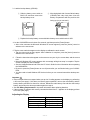
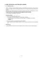
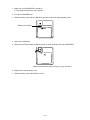
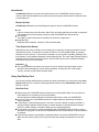
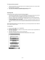
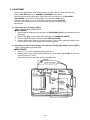
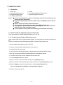
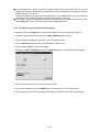
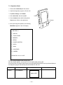
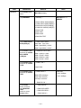
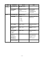
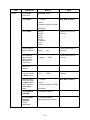
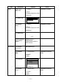
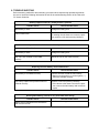
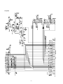
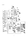
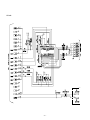
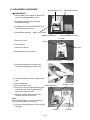
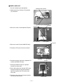
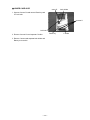
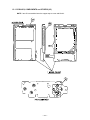
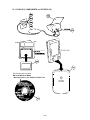
1
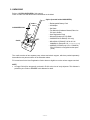
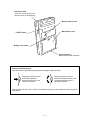
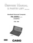
(without price)
Palm-size Personal Computer
E-100 (JX-530A)
E-105 (JX-530E)
MAY. 1999
E-100/105
INDEX
R
Ver.1
June / 1999
CONTENTS
1. SPECIFICATIONS ------------------------------------------------------------------------------- 1
2. UNPACKING -------------------------------------------------------------------------------------- 3
3. GENERAL GUIDE and INITIAL SETUP
3-1. General Guide ---------------------------------------------------------------------------- 4
3-2. Initial Setup ------------------------------------------------------------------------------- 6
4. RESET OPERATION and BATTERY REPLACEMENT
4-1. Reset Operation ------------------------------------------------------------------------- 9
4-2. Battery Replacement ---------------------------------------------------------------- 10
5. DATA TRANSFER
5-1. General ----------------------------------------------------------------------------------- 14
5-2. Data transfer between PC and E-100/105 ------------------------------------- 14
5-3. Infrared communications (Quotation from Microsoft User’s Guide) ------ 25
6. ADJUSTMENT --------------------------------------------------------------------------------- 26
7. OPERATION CHECK
7-1. Preparation ----------------------------------------------------------------------------7-2. How to install Diagnostic Program to E-100/105 --------------------------7-3. Operation Check ---------------------------------------------------------------------7-4. New (Second) version Diagnostic Program Rev. 0.50 --------------------
27
27
29
37
8. TROUBLESHOOTING ----------------------------------------------------------------------- 39
9. CIRCUIT EXPLANATION
9-1. Block Diagram ------------------------------------------------------------------------- 41
9-2. Power Supply -------------------------------------------------------------------------- 42
9-3. Function --------------------------------------------------------------------------------- 43
10. WIRING DIAGRAM --------------------------------------------------------------------------- 46
11. SCHEMATIC DIAGRAMS
11-1. Main Block (1/3) ~(3/3)--------------------------------------------------------------11-2. ROM Board -----------------------------------------------------------------------------11-3. Key Board ------------------------------------------------------------------------------11-4. Audio Block ----------------------------------------------------------------------------11-5. Cradle -------------------------------------------------------------------------------------
47
50
51
52
53
12. PCB VIEW (MAIN PCB) --------------------------------------------------------------------- 54
13. DISASSEMBLY PROCEDURE ------------------------------------------------------------ 56
14. PARTS LIST
14-1. PCB ASSY, COMPONENTS and OTHERS------------------------------------- 60
14-2. CRADLE ---------------------------------------------------------------------------------- 63
15. EXPLODED VIEW
15-1. PCB ASSY, COMPONENTS and OTHERS------------------------------------- 64
15-2. CRADLE ---------------------------------------------------------------------------------- 67
* Windows is a registered trademark of Microsoft Corporation in the U.S.A. and other countries.
* i486DX and Pentium are registered trademarks of Intel Corporation.
1. SPECIFICATIONS
Model:
Display:
E-100/E-105
240 × 320 dots
TFT Color LCD (65,536 colors)
CPU:
VR4121
Memory:
16/32MB
Interfaces:
Serial:
RS-232C, 115.2 kbps max.
Infrared: IrDA Ver. 1.0, 115.2 kbps (max.)
Range: 30 cm max.
Card Slot:
CompactFlash card, 3.3V Type I/Type II
Headphone jack:
ø 3.5 mm stereo output
Accepts monaural earphone,stereo earphones,stereo headphones.
Power Supply:
Main:
Rechargeable battery pack JK-210LT (Lithium-Ion battery)
AC adapter (AD-C50200)
Back-up: One CR2032 lithium battery
Power Consumption:
3.6 W
Approximate Battery Life (Normal Temperature)
Main:
(Actual time may be shorter due to conditions when charging.)
6 hours: Continuous input and data display at a ratio of 1:10,
with screen brightness at lowest possible level.
3 hours: Continuous communication using the optional modem
card (JK-711MC56), with screen brightness at lowest
possible level.
Back-up: 5 years: Main battery is charged or replaced immediately after
appearance of message to replace main battery.
2 weeks(E-100): No battery replacement after appearance of
message to replace main battery.
1 week(E-105):
No battery replacement after appearance of
message to replace main battery.
Approximate Charge Time (Normal Temperature)
5 to 6 hours: Charge time is longer for the first charges after purchasing the unit or installing a new battery pack.
Operating Temperature: 0°C to 40°C (32°F to 104°F)
Dimensions:
20H × 83.6W × 131.2D mm (3/4"H × 3 1/4"W × 51/8"D)
Weight:
255 g (9.0 oz)
—1—
Current consumption:
NOTES:
1. Be sure to measure after adjustment referring to 6.ADJUSTMENT of this manual.
2. When measuring these current, be sure to use suitable range analog ammeter.
Operation Mode
Main menu of OPERATION
CHECK in this manual
Input
Rechargeable Battery :
4.0V ± 0.1V
Current consumption
≤280mA
5. POWER CONTROL of
OPERATION CHECK of this manual
Rechargeable Battery :
4.0V ± 0.1V
≤600mA
5. POWER CONTROL of
OPERATION CHECK of this manual
AC Adapter : 5.0V ± 0.1V
≤600mA
Power/OFF
Rechargeable Battery :
4.0V ± 0.1V
≤1.4mA (E-100)
≤1.8mA (E-105)
Power/OFF
Lithium battery for Back-up
3.0V ± 0.1V
MAIN Battery = Rechargeable Battery (Lithium-lon battery)
≤950µA (E-100)
≤1.3mA (E-105)
Voltage Detectors: (Refer to CIRCUIT EXPLANATION of this manual.) :
VDET1B : 3.4 V ± 1% (Low battery message Rechargeable battery)
VDET2 : 3.2 V ± 1% (Forced power off)
VDETS : 2.7 V ± 1% (Low battery message for Back-up battery)
Operation Condition for Data transfer using IrDA :
Length (L)
Angle (A)
L ≤ 32 cm
A ≤ ±15˚
E-100
E-105
A
E-100
E-105
L
—2—
2. UNPACKING
Refer to 15. EXPLODED VIEW of this manual.
Check to make sure that all the items listed below are included.
Stylus (Inserted inside CASSIOPEIA )
•
•
•
•
CASSIOPEIA Unit
•
•
•
•
Cradle
•
Rechargeable Battery Pack
AC Adapter
Soft Case
Two Manuals (Hardware Manual,Palm-size
PC User’s Guide)
User Registration Card
Microsoft Windows CE CD-ROM
CASSIOPEIA CD-ROM (E-105 only)
MS AUDIO CD-ROM (E-105 for U.S.A /
CANADA/ for Europe & U.K. (not supplied for spare part))
AUDIBLE CD-ROM (only U.S.A / CANADA)
(This CD-ROM is not supplied as the spare
parts.)
The cradle consists of two separate parts, a base and a back support, which are packed separately.
Assemble the two parts as shown in the illustration above.
Fill out and send in the User Registration Card to become eligible to receive various support services!
NOTE
• A Floppy Disk will be temporarily enclosed in E-100 at the time of early shipment. This diskette is
preliminary one. Refer to README in this diskette for detail.
—3—
3. GENERAL GUIDE and INITIAL SETUP
3-1. General Guide
• Card Slot
• Charge indicator(Green)
Indicates battery pack is charging.
• Stereo headphone jack
For connection of a commercially available earphone/
headphone(ø3.5mm)
• Stylus
• Indicator lamp(Red)
Alerts you to alarms and warning
• Touch screen
Perform operations and input
data by tapping and writing
directly on the screen.
• Power button
Turns power on
and off.
• Exit button
Same as computer’s
ESC key.
• Menu
(Launcher)
• Contacts
• Calendar
• Action control
See “About the [Action]
Control” on the next page.
• Voice Yecorder button
(Program button)
Hold down to activate Voice
Recorder for instant recording of a voice memo.
• Speaker
• Cursor button
Moves the cursor around
the screen.
• Microphone
• Infrared port
• Program buttons
Press to launch
the assigned
program.
The programs
shown here are
the initial default
settings.
• AC adapter terminal
—4—
• Card lock switch
Locks the card in the slot so it
does not come out accidentally.
• Backup battery cover
• Main battery cover
• RESET button
• Battery cover switch
• Serial connector
Mates with the cradle connector.
About the [Action] Control
Operations can be performed by pressing and rotating the [Action] control.
Rotating the [Action] control
performs operations similar to the
up and down arrow keys of a
computer keyboard.
Pressing the [Action] control
performs an operation
similar to the Enter key of a
computer keyboard.
See the Palm-size PC User’s Guide for full details on [Action] control operations inside of specific
applications.
—5—
3-2. Initial Setup
Perform the following initial setup procedure after repair.
1. Load the main battery (rechargeable battery pack).
Be sure to use the AC Adapter to charge the rechargeable battery pack before doing
anything else. Your CASSIOPEIA will not operate correctly if you load the backup battery
before charging the battery pack.
1 Slide the battery cover switch to
MAIN and remove the main battery
cover.
2 Install the rechargeable battery pack that
comes with the CASSIOPEIA. Make sure
that the battery pack is oriented correctly.
3 Replace the main battery cover.
4 Slide the battery cover switch to LOCK.
2. Use the AC Adapter to charge the battery pack for about five or six hours.
• Connect the AC Adapter to the CASSIOPEIA as shown in the illustration.
•
•
•
•
Charging starts automatically as soon as you connect the AC Adapter to the CASSIOPEIA .
The charge indicator is green while charging is in progress. It goes out when charging is complete.
It takes about five or six hours to reach full charge.
The time required to reach full charge may be longer the first time you charge the battery pack after
purchasing it.
Remove the AC Adapter from the CASSIOPEIA after charging is complete.
—6—
3. Load the backup battery (CR2032).
2 After wiping both side of a new lithium battery
(CR2032) with a dry cloth, place it into the
battery compartment with the positive side
facing up (so you can see it).
1 Slide the battery cover switch to
BACK UP, and then remove the
backup battery cover.
3 Replace the backup battery cover and slide the battery cover switch back to LOCK.
4. Let the CASSIOPEIA rest for about five seconds, and then press the [Power] button.
• After a few moments the Microsoft Windows CE screen appears, press the [Action] control to
advance to the next screen.
5. Tap the cross marks that appear on the display to calibrate the touch screen.
• Tap the cross marks as they appear. After calibration is complete, press the [Action] control to
advance to the next screen.
6.
•
•
•
•
Follow the instructions that appear on the screen to set your city, the current date, and the current
time.
Microsoft Windows CE screen appears with a message telling that setup is complete. Tap the
screen to display the Active Desktop.
See the Hardware Manual and Palm-size PC User's Guide for other information about operating
the CASSIOPEIA.
Be sure to press the [Power] button to turn off power after you are finished using your CASSIOPEIA.
You also need to install Windows CE Services before you can communicate with a desktop computer.
Important
• If the touch panel does not respond when you tap it or if nothing appears on the display, try performing
a full reset (next page). If this does not restore proper operation, remove the main battery and the
backup battery and wait for about five minutes. Reload the main battery first and then the backup
battery, and perform the above procedure again from step 4.
• See 4-2. Battery Replacement for important information about replacing batteries.
• If the message "A problem with memory contents has been found..." appears on the display, perform
a full reset (next page).
Adjusting the Display
To do this:
Make contrast darker
Make contrast lighter
Increase brightness
Decrease brightness
Perform this operation:
[Exit] + Cursor up
[Exit] + Cursor down
[Exit] + Cursor right
[Exit] + Cursor left
—7—
■ Full Reset (Memory Initialize)
Full reset (memory initialize) deletes all data, and resets all unit parameters to their initial defaults.
The following are conditions when you should perform a full reset.
•
•
•
•
When you want to delete all memory data and return unit settings to their factory defaults.
When you forget your password and need to clear it.
When a data error causes operational problems.
Appearance of the message: “A problem with memory contents has been found···”.
Important
• If there is a CompactFlash card in the CASSIOPEIA's slot, remove the card before performing the full
reset.
• The following procedure deletes all data in memory. Be sure that data is backed up or that you no
longer need it before performing the following procedure.
1. Make sure that unit power is turned on.
2. While holding down the [Power] button, use the stylus to hold down the RESET button for about two
seconds.
• This causes the following message to appear on the display screen.
Proceeding with this operation initializes memory. Press [Action] to proceed or [Exit] to cancel.
3. Press the [Action] control.
• This causes the following message to appear on the display screen.
Proceeding with this operation deletes all data stored in memory. Press [Action] to proceed or
[Exit] to cancel.
4. Press the [Action] control again.
• This starts the full reset operation, which deletes all data in memory.
• Pressing the [Action] control displays the Startup screen followed by the touch screen calibration
screen.
You can abort the full reset operation while the messages in steps 2 and 3 are on the display by pressing
the [Exit] button.
If a full reset does not correct the problem, remove the main battery and the backup battery and
leave them out for about five minutes. Next, restart the setup operation from step 1. Make sure
that the positive (+) and negative (–) terminals are oriented correctly when you reload them into
the unit.
—8—
4. RESET OPERATION and BATTERY REPLACEMENT
4-1. Reset Operation
“Reset” is similar to a computer reboot. Performing a reset deletes any data that is in the process of
being input or edited, without yet being saved. Data stored in memory and all settings, however, are
retained.
Perform the reset operation whenever the unit fails to operate correctly due to operational error or some
other abnormality. Any of the following symptoms indicate that reset is required.
• Failure of the unit to respond when the screen is tapped or a button is pressed.
• The hourglass icon remaining on the screen.
Performing a Reset
1. Use the stylus to press the RESET button.
• The unit performs a reset followed by a memory check operation.
If no data error is found, the following two screens appear on the display in succession.
• Startup screen
• Desktop
2. Normal unit operation is possible after the desktop appears.
• Since memory data and settings are retained, you can continue operation from where you last left
off.
Important
• If the above operation does not solve the problem, perform a full reset (memory initialize page 8).
—9—
4-2. Battery Replacement
You CASSIOPEIA is powered by a dual power supply that consists of a main battery (rechargeable
battery pack) and a backup battery (CR2032 lithium battery).
• We recommend that you use the Power properties dialog to keep informed about the current levels of
your main and backup batteries. See the separate Palm-size PC User’s Guide for more information
about this dialog.
• Icons appear in the Taskbar to let you know when battery power is low. See the separate Plam-size PC
User’s Guide for more information about these icons.
Important
The following messages appear whenever battery power drops below a certain level.
Main Battery
Recharge the battery pack as soon as possible after the following message appears.
“Prevent possible data loss by promptly replacing or recharging your main batteries according
to your hardware manufacturer’s instructions.”
Backup Battery
Replace the backup battery as soon as possible after the following message appears.
“Prevent possible data loss by promptly replacing or recharging your backup battery according
to your hardware manufacturer’s instructions.”
• Data stored in memory can be lost if you continue operation after the low battery message appears or
if you incorrectly load batteries. Be sure to always back up important data on your desktop computer
hard disk or on a CompactFlash memory card. See the separate Palm-size PC User’s Guide for
information about backing up data.
• See the separate Plam-size PC User’s Guide for information about using the Card Backup Tool program to back up data to a CompactFlash memory card.
• Never remove the main battery and backup battery from the CASSIOPEIA at the same time. Doing so
causes all data stored in memory to be deleted.
• Should the main battery and the backup battery both require replacement, be sure to always replace
the main battery first.
• Use the rechargeable battery pack for the main battery and a CR2032 lithium battery for the backup
battery. Never use any other type of batteries.
If unit power turns off due to insufficient power, the following warning message appears on the display
the next time you turn on unit power.
“Warning
Due to high current demand by hardware, the system powered down in order to protect memory
contents...”
If unit power turns off due to sudden power drain by a CompactFlash card, the following warning message appears on the display the next time you turn on unit power.
“Warning
Due to high current demand by the card, the system powered down in order to protect memory
contents...”
Important
Be sure to observe the following important battery handling precautions. Failure to do so can cause
batteries to leak, resulting in damage to surrounding items and create the danger of fire and electrical
shock.
— 10 —
• Always make sure that the positive (+) and negative (–) poles of the batteries are oriented correctly.
• Use only the types of batteries specified for use with this unit.
• Charge the battery pack in an area where the temperature is between 10˚C (50˚F) and 35˚C (95˚F).
Charging in areas that are very cold or exposed to direct sunlight can cause deterioration and leaking
of the battery pack.
• To avoid deterioration and leaking, the battery pack is designed to discharge even when you do not
use the CASSIOPEIA. Be sure to recharge the battery pack at least once every three months, regardless of how much you use the CASSIOPEIA during that time.
• A battery pack that loses power too quickly after it is charged is probably near the end of its service life.
In such a case, you have to purchase a new battery pack.
Replacing the Main Battery
1. Make sure your CASSIOPEIA is turned off.
• Press the [Power] button to turn off power.
2. Turn the CASSIOPEIA over.
3. Slide the battery cover switch to MAIN, and then remove the main battery cover.
4. Remove the main battery and then load a new battery pack.
• Make sure the battery pack is oriented correctly.
5. Replace the main battery cover.
6. Slide the battery cover switch to LOCK.
Replacing the Back-up Battery
Important
• Never remove the main battery and back-up battery from the CASSIOPEIA at the same time. Doing so
causes all data stored in memory to be deleted.
• Should the main battery and the back-up battery both require replacement, be sure to always replace
the main battery first.
• Be sure to replace the back-up battery as soon as possible whenever the following message appears
on the display: “Prevent possible data loss by promptly replacing or recharging your back-up
battery according to your hardware manufacturer’s instructions”.
— 11 —
1. Make sure your CASSIOPEIA is turned off.
• Press the [Power] button to turn off power.
2. Turn the CASSIOPEIA over.
3. Slide the battery cover switch to BACK UP, and then remove the backup battery cover.
Battery cover switch
4. Remove the old battery.
5. Wipe off a new lithium battery (CR2032) with a dry cloth, and load it into the CASSIOPEIA.
Make sure the positive side is facing up, so you can see it.
6. Replace the back-up battery cover.
7. Slide the battery cover switch back to LOCK.
— 12 —
Charging the Battery Pack
1. Install the battery pack into the CASSIOPEIA.
2. Attach the AC adapter to the cradle and place the CASSIOPEIA onto the cradle.
•
•
•
•
Charging starts automatically as soon as you place the CASSIOPEIA onto the cradle.
The charge indicator is green while charging is in progress. It goes out when charging is complete.
It takes about five or six hours to reach full charge if this pack is entirely discharged.
You can use your CASSIOPEIA while the battery pack is charging.
Important
• Do not use the CASSIOPEIA while it is charging for the first time after you purchased it or for the first
time after you installed a newly purchased battery pack.
• If the battery pack dose not achieve full charge after the nomal charge time, remove the CASSIOPEIA
or unplug the AC adapter from the cradle to stop charging.
Remove the CASSIOPEIA from the cradle after charging is complete.
The followeing illustration shows how to connect the AC adapter directly to the CASSIOPEIA for charging.
• Charging starts automatically as soon as you attach the AC adapter to the CASSIOPEIA.
• Direct connection charging conditions are the same as those described for cradle charging above.
— 13 —
5. DATA TRANSFER
5-1. General
There are basically four kinds of data transfers concerning E-100/105.
1. Data transfer between PC and E-100/105 using the software of Windows CE Services (Ver. 2.2)
refers to Memory Backup/ Restore described in latter page concerning this transfer.
2. Data transfer between E-100/105 and Compact Flash memory card
refers to Card Backup Tool described in latter page concerning this transfer.
It is recommended that CF-15 (15MB)/ CF-30 (30MB) is used for this transfer.
3. Infrared Communications - For example, data transfer between a E-100/105 and another E-100/
105 unit using IrDA.
4. Modem communication using the optional modem (JK-711MC56) (U.S. and Canada Only)
refers to User’s Guide for JK-711MC56 concerning this modem.
NOTE:
■ It is recommended that AC adapter is used at the time of data transfer by item 1 ~ 4 described
above.
■ Important!
Data saved in E-100/105 will be deleted by electrical shock (Static Electricity, External Nose
and so on) or the other reasons. Be sure to save data in PC or Compact Flash memory card
usually using data transfer by item 1 and 2 described above.
“Card Backup tool” is the software developed to prevent from this trouble.
5-2. Data transfer between PC and E-100/105
■ Required System Configuration
The minimum system configuration required to connect the cradle and perform data communications is described below. This system configuration also makes it possible to install and use Windows CE Services, which is included on the Microsoft CD-ROM provided with the unit.
Minimum Desktop Computer Requirements
• Microsoft Windows NT Workstation 4.0 or Windows 95/98 (U.S.version)
• Desktop computer with a Pentium processor for Windows NT.
• Desktop computer with a 486/66 DX or higher processor (Pentium P90 recommended) for Windows 95/98
• 16 MB of memory for Windows 95/98 (More memory improves performance.) or Windows NT
Workstation 4.0 (32 MB recommended for Windows NT)
• Hard disk drive with 10 to 50 MB of available hard disk space (Actual requirements vary based on
selection of features and user’s current system configuration)
• Available 9 or 25 pin communications port (adapter required for 25 pin communication port)
• One CD-ROM drive
• VGA or higher-resolution graphics card (Super VGA 256-color recommended)
• Keyboard
• Microsoft Mouse or compatible pointing device
Options for either Windows NT Workstation 4.0 or Windows 95/98
•
•
•
•
•
Audio card/speakers for sound
Microsoft Office 97 or Microsoft Office 95
Serial or built-in infrared adapter for synchronization (Windows 95/98 only)
Modem for remote synchronization
Ethernet LAN connection for remote synchronization
Requirements for Mobile Channels Support
• Micorosoft Internet Explorer 4.0 (included on CD), which requires 40 MB to 70 MB of hard disk
space and a minimum 486/66 processor. Service Pack 3 (or higher) is required for Windows NT
systems (included on CD).
NOTE:
Different minimum system requirements are required when using the applications included on the
CASSIOPEIA CD-ROM. See the documentation contained on the CD-ROM for full details.
— 14 —
■Memory Backup / Restore
Make the backup copy by Windows CE Services 2.2 to your PC before repairing E-100/105, and
restore the data from PC to user’s E-100/105 after repairing.
For the details of Backup/ Restore, refer to User’s Guide for the Palm-size PC .
Notes:
1. Backup program of Windows CE Services 2.2 back up only files and databases.
The data entered in Owner, World Clock mode and so on can not be backed up to PC.
2. Use AC adapter when making backup copy and restoring.
3. It is necessary to install Windows CE Service 2.2 to PC before these data transfer.
Refer to User’s Guide for Palm-size PC concerning the installation of Windows CE Service
2.2.
Backup
1. Connect E-100/105 to your PC with the cradle.
2. Clicking Mobile Devices icon, start Windows CE Services 2.2 on your PC.
3. Windows CE Services 2.2 automatically detects E-100/105 connected to PC.
4. The following screen will be displayed.
5. Selecting “Browse”, the following Guest icon will be automatically displayed on the screen.
If not displayed, select Palm-size_PC, and then return to this top menu of Mobile Devices again.
6. Select “Backup/Restore....” from “Tools” pop up menu.
7. Select “Full: back up all data”, then click “Back Up Now” button.
— 15 —
8. Confirm the file name of back up copy (Backup.stg). Remember or record the directory which its file
is backed up also. For example: C\Program File\Windows CE Service\Profiles\Guest\Backup.stg
And then, after selecting OK button, Full Backup starts.
— 16 —
Restore
Perform the following procedure for restoring after repair.
1. Turn on E-100/105.
2. After pressing Action button while holding down Power button, perform touch panel calibration on
E-100/105, and then skip the other setups after calibration (Full RESET).
3. Connect E-100/105 to your PC with the cradle.
4. Window CE Services 2.2 automatically detects E-100/105 connected to PC.
5. Clicking Mobile Devices icon, starts Windows CE Services 2.2 on your PC.
6. The following screen will be displayed.
Selecting “Browse”, the following Guest icon will
be automatically displayed on the screen.
If not displayed, select Palm-size_PC, and then
return to this top menu of Mobile Devices again.
7. Select “Backup/Restore....” from “Tools” pop up menu.
8. Selecting “Restore”, the following screen appears.
9. After selecting Restore Now button, the following screen will appear.
— 17 —
10.Detect Back up.stg file using Browse... button. After you succeed in this detection, the following
screen appears.
11. Selecting OK button, the following screen will appear.
12. After selecting Restore button, the data transfer from PC to E-100/105 starts.
13. The following screen will appear after this data transfer.
Finally, click OK button.
— 18 —
■At present, there are four kinds of Compact Flash memory cards as follows.
CF-2 (2MB)/ CF-4 (4MB)/ CF-10 (10MB)/ CF-15 (15MB)/ CF-30 (30MB)/ CF-48 (48MB)
■How to save the data to Compact Flash memory card without PC
(Applicable to only “Note Taker” and “Voice Recorder” mode as well as E-10/ E-15)
< PROCEDURE >
1. Note Taker
(1) Tap Start, and then Note Take.
(2) Tap
icon, Tools, Options, and then Columns.
(3) Select Location.
(4) Tap Save, and then select Save to storage card.
(5) Tap OK.
(6) Make any new file.
(7) Confirm that Location is set to Storage C....
* Removing Compact Flash memory card (CF card), data saved in E-100/105 will disappear.
After inserting CF card into slot of E-100/105 again, open Note Taker, tap File, and then tap Select
All. Doing so, data will appear again.
2. Voice Recorder
1 Tap Start, and then Voice Recorder.
2 Tap
icon, Tools, Options, and then General.
3 Select Save to storage card, and then tap Columns.
4 Select Location, and then tap OK.
5 Make any new file.
6 Confirm that Location is set to Storage C....
* Removing Compact Flash memory card (CF card), data saved in E-100/105 will disappear.
After inserting CF card into slot of E-100/105 again, open Voice Recorder, tap File, and then tap
Select All. Doing so, data will appear again.
■Card Backup Tool
In the CD-ROM of item 60 (SOFTWARE/CD-ROM (CASIO)) described in PARTS LIST of this Service
Manual, there is User’s Guide for “Card Backup Tool” software.
After set this CD-ROM to your PC, open the holders as follows;
Bonus Software> Card Backup Tool> View User’s Guide
— 19 —
■ User's Guide for Card Backup Tool
Contents
INTRODUCTION .........................................................................................................................
BACKED UP DATA ..........................................................................................................
TIME REQUIRED FOR BACKUP .....................................................................................
USING CARD BACKUP TOOL ...................................................................................................
READ THIS FIRST! ..........................................................................................................
BACKING UP DATA .........................................................................................................
RESTORING DATA ..........................................................................................................
DELETING A BACKUP FILE ............................................................................................
21
21
21
21
21
22
23
24
Trademarks
Microsoft, Windows, and Windows NT are either registered trademarks or trademarks of Microsoft
Corporation in the United States and/or other countries.
All other products and company names mentioned herein may be the trademarks of their respective
owners.
• The contents of this document are subject to change without notice.
• In no event shall CASIO COMPUTER CO., LTD. be liable to anyone for special, collateral, incidental, or consequential damages in connection with or arising out of the purchase or use of these
materials. Moreover, CASIO COMPUTER CO., LTD. shall not be liable for any claim of any kind
whatsoever against the use of these materials by any other party.
• This manual and the software it describes are owned by CASIO COMPUTER CO., LTD. The
structure, organization and code of the software are the valuable trade secrets of CASIO.
• The operations described in this manual assume that you are already familiar with the basic operation of Windows CE. See the documentation that comes with Windows CE for full details on its
operation.
• Sample displays shown in this manual may differ somewhat from the displays actually produced
by the product.
Copyright Notice
No part of this publication may be reproduced, transmitted, transcribed, stored in a retrieval system,
or translated into any human or computer language, in any form or by any means, without the
express written permission of CASIO COMPUTER CO., LTD.
Copyright 1999 CASIO COMPUTER CO., LTD. All rights reserved.
— 20 —
Introduction
Card Backup Tool lets you quickly and easily back up your CASSIOPEIA memory data to a
memory card. Backed up data lets you easily restore your system should it start to malfunction due
to some data error.
Backed Up Data
Card Backup Tool backs up the following three types of data in CASSIOPEIA memory.
• Files
Files are created using Voice Recorder, Note Taker, and other applications and add-on programs.
Files transferred from your desktop computer to the CASSIOPEIA are also backed up.
• The Registry
The registry contains setup data for Windows CE and built-in applications.
• Database Data
Database data is Calendar, Contacts, Tasks, and Inbox data.
Time Required for Backup
Depending on the volume of data you are backing up (or restoring), the backup operation can take
anywhere from about 10 seconds to a number of minutes. To back up 4MB of data, for example
takes three or four minutes. To check how much data is on your system, tap [Start], [Settings], and
then [System]. On the dialog that appears, tap the [Memory] tab. The value under [Storage memory]
indicates how much data is stored in memory. See the Palm-size PC User's Guide and CASSIOPEIA online help for more information.
Important!
• The restore operation can take a very long time if you do not have enough storage memory
allocated. When this happens, quit the restore operation, increase the size of the storage
memory, and then try the restore operation again.
Using Card Backup Tool
This section provides details about the backup and restore operations you can perform using Card
Backup Tool. Be sure to read the following precautions before using Card Backup Tool for either
backup or restore.
Read this first!
• Always reset your CASSIOPEIA before backing up or restoring data. Make sure you perform a
reset operation. Do not perform a full reset operation!
See the separate Hardware Manual for information about how to reset your CASSIOPEIA.
• Be sure to power your CASSIOPEIA with the AC adapter whenever performing a backup or
restore operation.
• If main battery or backup battery power is low when you start a backup or restore operation, a
warning message appears and the backup or restore operation is cancelled. Before starting a
backup or restore operation, charge the battery pack or load new batteries.
• Do not perform any button or screen operations on the CASSIOPEIA while a backup or restore
operation is in progress. Do not touch the CASSIOPEIA at all until the backup or restore operation
is complete.
• Files and other data are automatically compressed before it is stored in CASSIOPEIA memory.
Make sure the memory card you are using for backup has enough unused space to store the
data.
— 21 —
Backing Up Data
Use the following procedure to back up data. Make sure you read the precautions under "Read this
first!" on the previous page before starting.
To back up data
1.
2.
3.
4.
•
Connect the AC adapter to your CASSIOPEIA.
Reset the CASSIOPEIA.
Insert a memory card with sufficient free space to store the backup data into the CompactFlash
card slot of the CASSIOPEIA.
Tap [Start], [Programs], [Utility], and then [Card Backup].
This starts up Card Backup Tool and causes the dialog shown below to appear.
If the memory card already contains
backup data, the date of the last
backup appears here.
This area shows the amount of free
space on the memory card and the
amount of CASSIOPEIA data memory
that is used.
5.
•
Tap [Backup now].
This causes the dialog shown below to appear.
6.
•
•
7.
Tab [Yes] to start the backup or [No] to close the dialog without backing up anything.
An hourglass icon on the screen indicates that the backup operation is being performed.
The message "Backup complete!" appears on the display after the backup operation is complete.
After backup is complete, tap [OK] to quit Card Backup Tool.
Note
• If the backup operation is interrupted or unsuccessful for any reason and there is a previous
backup file on the memory card you are using, the previous file remains intact on the card.
— 22 —
To interrupt a backup operation
1.
•
2.
Tap the [x] close button in the upper right corner of message box that is on the screen while a
backup operation is in progress.
This causes the message "Do you really want to cancel?" to appear.
Tap [Yes] to cancel the backup operation or [No] to resume it.
Restoring Data
Performing the restore operation causes the following to happen.
• If the same file or registry data exists in both CASSIOPEIA memory and on the memory card, the
data in CASSIOPEIA memory is overwritten with the data on the memory card.
• Any files or registry data in CASSIOPEIA memory that is not on the memory card is left as-is.
• Calendar, Contacts, Tasks, and Inbox data in CASSIOPEIA memory is all overwritten with the
corresponding data from the memory card.
• To return CASSIOPEIA to the exact status it was when you backed up the data, perform a full
reset before restoring the data. See the separate Hardware Manual for information about the full
reset.
Use the following procedure to restore data. Make sure you read the precautions under "Read this
first!" on page 21 before starting.
To restore data
1.
2.
3.
4.
•
Connect the AC adapter to your CASSIOPEIA.
Reset the CASSIOPEIA.
Insert the memory card that contains the data you want to restore into the CompactFlash card
slot of the CASSIOPEIA.
Tap [Start], [Programs], [Utility], and then [Card Backup].
This starts up Card Backup Tool and causes the dialog shown below to appear.
— 23 —
5.
•
6.
•
•
7.
8.
Tap [Restore now].
This causes the dialog shown below to appear.
Tab [Yes] to start the restore or [No] to close the dialog without restoring anything.
An hourglass icon on the screen indicates that the restore operation is being performed.
The message "Restore complete!" appears on the display after the restore operation is complete.
After restore is complete, tap [OK] to quit Card Backup Tool.
Reset your CASIOPEIA again.
To interrupt a restore operation
1. Tap the [x] close button in the upper right corner of message box that is on the screen while a
restore operation is in progress.
• This causes the message "Do you really want to cancel?" to appear.
2. Tap [Yes] to cancel the restore operation or [No] to resume it.
Deleting a Backup File
You can use the following procedure to delete the backup files you created using Card Backup Tool.
Delete a file when you no longer need it, when you want to free up space on a memory card, etc.
To delete a backup file
1.
2.
•
3.
•
Insert the memory card that contains the backup file you want to delete into the CompactFlash
card slot of the CASSIOPEIA.
Tap [Start], [Programs], [Utility], and then [Card Backup].
This starts up Card Backup Tool.
Tap [Backup File Delete].
This causes the dialog shown below to appear.
4.
Tab [Yes] to delete the backup file or [No] to close the dialog without deleting anything.
— 24 —
5-3.Infrared Communications (Quotation from the Microsoft User's Guide)
Your Palm-size PC has an infrared port that you can use to exchange information with another Windows CE device. In Contacts, for example, you can send up to 25 cards at a time to another Windows
CE device. In Voice Recorder and Note Taker, you can send individual files or notes.
Note Taker Infrared Send Menu
To transfer data with infrared
1.Align the infrared port of your Palm-size PC with the infrared port of the other Windows CE device.
•
The two infrared ports should be within about 30cm (≤32cm) from each other.
2.
On the sending unit, start up the program that contains the data you want to send. Select the
items you want to send, and then tap File, Send To, and then Infrared Recipient.
3.
•
On the receiving unit, start up the same program, and then tap File and then Receive.
The displays of both units show a message indicating that data transfer is being performed. Both
units play a sound and display a message when transfer is complete.
— 25 —
6. ADJUSTMENT
There are two adjustments using variable resistors (VR300/ VR301) concerning E-100/-105.
Refer to Main Block (3/3) of 11. SCHEMATIC DIAGRAM of this manual.
Before performing these adjustments, remove the lower case referring to 13. DIASSEBLY
PROCEDURE of this manual. Set the battery cover switch to LOCK position.
And then, after adding 4.0 ± 0.1V to the battery terminal, perform Full RESET.
Therefore, save Use's data to PC or Compact Flash memory card before these
adjustments.
6-1. Adjustment for LCD Display (VR300)
Refer to the illustration described below.
■ PROCEDURE
1. Install Diagnostic program to unit referring to 7. OPERATION CHECK of this manual before this
adjustment.
2. Display "ALL gray" screen shown to the final page in 7. OPERATION CHECK.
3. Remove AUDIO PCB ASSY (item 38 of 15-1. EXPLODED VIEW).
4. Rotating VR300 using ceramic screw driver (minus/ 1.8 mm width), adjust this display to become no flicker. Flickers will appear due to wrong adjustment.
6-2. Adjustment for Vref Terminal Voltage of IC (IC303) for Rechargeable Battery Control (VR301)
Refer to the illustration described below.
■ PROCEDURE
1. Add 4.0 ± 0.1V to the rechargeable battery terminal (+).
2. Rotating VR301 using ceramic screw driver (minus/ 1.8 mm width), adjust VREF terminal voltage to become 4.17~4.20 V.
Green LED on the unit will flicker due to wrong adjustment.
— 26 —
7. OPERATION CHECK
7-1. Preparation
1.
2.
3.
4.
E-100/ -105
Compact Flash memory card
Rechargeable battery pack
AC adapter (AD-C50200)
Notes:
5. Cradle
6. PC installed Windows CE Services 2.2
7. Diagnostic program (Diag. exe)
■ Be sure to make back-up copies of all important data in E-100/-105 because this
check make these data deleted.
■ Diagnostic program (Diag. exe) exist in SOFT holder of CD-ROM for Service information Disk.
■ After all checks are finished, perform Full Reset.
If not performed, this program remains to exist in RAM of E-100/ -105.
■ The program file names (Diag.exe/ CASIO_JX500diag.exe) are the same names as
ones of E-10/-15. Take care not to confuse.
■ To enter operation check, perform the following procedures after Initial Setup.
7-2. How to install the diagnostic program to E-100/-105
There are two ways to install the diagnostic program to E-100/-105.
7-2-1. The way of using Compact Flash memory card
Using Compact Flash memory card saved this program, you can perform the operation check without
PC.
At first, It is necessary to save the diagnostic program to Compact Flash memory card.
1. Set a Compact Flash memory card to E-100/-105.
2. Connect a cradle and PC installed Windows CE Services 2.2.
3. Set this E-100/-105 to this cradle.
4. E-100/-105 will be automatically turned on, and then the communication with PC will start.
5. After this communication, Mobile Devices window will be automatically opened.
6. Five folder will be made in Guest of Mobile Devices window also.
7. Click the Storage Card folder in Guest.
8. Make a new folder in this folder. Make its folder name jx520diag precisely.
9. Make a new folder in this jx530diag folder. Make its folder name casioconfidential precisely.
10.Enter the Diag.exe program file described above in this casioconfidential folder.
(Directory: Storage Card> jx530diag> casioconfidential> Diag.exe)
11.Finish to communicate with PC.
— 27 —
■ Once the diagnostic program is saved to Compact Flash memory card and E-100/-105, you can
perform this operation check without Compact Flash memory card because this program is saved to
D-RAM memory in E-100/-105.
Even if you delete this program saved to RAM memory by Full RESET and so on, you can perform
this operation check after inserting this Compact Flash memory card again.
■ If you want to delete quite diagnostic program file (Diag.exe file) in Compact Flash memory card,
delete Diag.exe file at the time of the communication described above.
7-2-2. The way of using no Compact Flash memory
1. Make the copy of the Diag.exe file using another medium for memory (floppy disk, HD etc.).
2. Change its copied file name (Diag.exe) for CASIO_JX500diag.exe precisely.
3. Start to communicate between PC and E-100/-105 using the cradle.
4. Open the Windows folder in Guest of the Windows CE Services 2.2.
5. If any message appears, reply to its message.
6. Entering its CASIO_JX500diag.exe file in this Windows folder, the following screen will appear.
7. After this procedure, pull out E-100/-105 from the cradle.
8. It is recommended that you press RESET button on the back of E-100/-105 after item 6.
9. The operation check can be started after performing the procedure described to the next page.
— 28 —
7-3. Operation Check
1. Perform 3-2. Initial Setup of this manual.
2. Install the diagnostic program to E-100/-105.
3. Tap Start, Settings, and Taskbar.
4. Select Auto hide, and then tap OK.
Power
5. Press Contacts button while holding down
Power button. Refer to the right figure.
Contacts
6. After performing this operation, the following
Main Menu appears in the LCD display.
** Main Menu **
1 DISPLAY
2 TOUCH PANEL
3 MEMORY
4 SERIAL
5 POWER CONTROL
6 AUDIO
7 Others
8 COLOR BAR
9 CAMERA
CPROG Rev. xxx for Jx-537
In case of using Compact Flash memory card:
After this display appears, you may pull out its Compact Flash memory card.
Even if there are no Compact Flash memory card, this OPERATION CHECK can be performed because
the diagnostic program was already saved to D-RAM of E-100/-105.
ITEM
Display
OPERATION
DISPLAY
Tap 1 DISPLAY.
Medium RED
— 29 —
NOTE
ITEM
Display
OPERATION
DISPLAY
NOTE
Tap the panel.
Medium GREEN
Tap the panel.
Medium BLUE
Touch panel
Tap the panel.
No display
Tap the panel.
All dots
Tap the panel twice.
Main Menu display
Tap 2 TOUCH
PANEL.
** Touch Panel **
1 Case
2 Points
3 Cross
— 30 —
ITEM
Touch panel
OPERATION
DISPLAY
Tap 1Case.
Case ---> OK
Press Action button.
** Touch Panel **
NOTE
1 Case
2 Points
3 Cross
Tap 2 Points.
Tap four crosses
in any order.
Touch Panel -----> OK
Press Action button
** Touch Panel **
NG if any crosses
remain on the display
after tapping all four
crosses.
1 Case
2 Points
3 Cross
Tap 3 Cross.
Trace on the
center of the two
black lines in the
direction shown to
the right arrows.
2nd
1st
— 31 —
OK if two lines are
reversed as shown to
the left.
Trace lines while
pressing with stylus
strongly.
ITEM
MEMORY
OPERATION
DISPLAY
Press Action button
twice.
Main Menu display
Tap 3 MEMORY.
** Memory **
NOTE
Main Menu for 3
MEMORY
1 ROM CHECK SUM(32MByte)
1 'ROM CHECK SUM(16MByte)
2 ROM BUS CHECK(32MByte)
2 'ROM BUS CHECK(16KByTE)
3 ROM TYPE
4 RAM TEST
5 RAM LOOP
6 RAM R/W TEST
Tap 1 ROM CHECK
SUM (32Kbyte).
** ROM CHECK SUM **
base addr. Sum value
SUM 1 (beXXXXX) = XXXX
SUM 2 (beXXXXX) = XXXX
Press Action button,
and then tap 2 ROM
BUS CHECK
(32Kbyte).
** ROM BUS CHECK SUM **
SUM 1 (HIGH) = XXXX
SUM 1 (LOW) = XXXX
SUM 2 (HIGH) = XXXX
SUM 2 (LOW) = XXXX
Press Action button,
and then tap 3 ROM
TYPE.
** ROM TYPE **
Mask ROM
Press Action button,
and then tap 4 RAM
TEST.
** RAM CHECK **
RAM SIZE=XX Mbyte
Start addr=XXXXXX
Chk byte =XXXXXX
-- RAM CHK OK --
Press Action
button, and then
tap 6 RAM R/W
TEST.
And then, press
Action button.
** RAM CHECK **
-- RAM DATA WRITE –
-- RAM DATA READ –
-- RAM CHK OK --
— 32 —
RAM SIZE:
E-100: 16MByte
E-105: 32MByte
ITEM
POWER
CONTROL
AUDIO
OPERATION
DISPLAY
Press Action button
twice.
Main Menu display
Tap 5 POWER
CONTROL.
Currently CPU clock is
131MHz
Push Action key to exit
Press Action button.
Main Menu display
Tap 6 AUDIO.
** Audio **
NOTE
Refer to Current
consumption of
1. SPECIFICATION
of this manual.
To regain this menu, press
Action button.
1 0.5kHz
2 1kHz
3 2kHz
4 Record
Tap 1 0.5kHz.
AUDIO 0.5kHz
Sound of AC 0.5kHz is
emitted.
After tap Action
button, tap
2 1kHz.
AUDIO 1kHz
Sound of AC 1kHz is
emitted.
After tap Action
button, tap
3 2kHz.
AUDIO 2kHz
Sound of AC 2kHz is
emitted.
Connect a
earphone to
E-100/-105.
After tap Action
button, tap
4 LR-Channel.
AUDIO LR-Channel
Hear the repeating
stereo human voice
“Left channel/ Right
channel ..............”
using a earphone.
Remove a earphone
— 33 —
ITEM
Others
OPERATION
Press Action
button twice.
Tap 7 Others.
DISPLAY
NOTE
Main Menu display
** Others **
Main Menu of Others
1 Switch
2 Compact Flash(CDs, CDOR)
...........................
6 BackLight
Tap 1 Switch.
VDET1R
VDET2R
VDET3
VDETS
VDETCF
AC Adapter
Cover
Charge
Confirm that red LED is
flickering.
Remove Backup
battery (CR2032).
.............................................
VDETS
ON
.............................................
Confirm that red LED is
flickering.
After installing
Backup battery
again, connect
AC Adapter to
E-100/-105.
............................................
AC Adapter
USED
.............................................
Confirm that red LED is
flickering.
.............................................
Cover
OPEN
..............................................
Confirm that red LED is
flickering.
Remove AC
Adapter.
Slide the battery
cover lock switch
to MAIN position.
Slide the battery
cover lock switch
to LOCK position
again. And then,
press Action
button.
** Others **
1 Switch
2 Compact Flash(CDs, CDOR)
...........................
6 BackLight
Tap 3 Keyboard
RANDAM.
** Keyboard Random **
Press Calendar,
Launcher,
Contacts ........
buttons
sequentially.
** Keyboard Random **
Calendar Launcher Contacts
.......................
— 34 —
Main Menu of Others
ITEM
Others
OPERATION
Finally, press
EXIT button.
DISPLAY
** Others **
NOTE
Main Menu of Others
1 Switch
2 Compact Flash(CDs, CDOR)
...........................
6 BackLight
Tap 5 Disk Loop.
Press Action
button
** Others **
Main Menu of Others
1 Switch
2 Compact Flash(CDs, CDOR)
...........................
6 BackLight
Tap 6 BackLight.
183
COLOR BAR
Press UP/ DOWN
keys of Cursor
button.
Display becomes
lighter/ dimmer.
And the number displayed
below changes.
Press Action
button twice.
Main Menu display
Tap 8 COLOR
BAR.
** COLOR BAR **
Main Menu of COLOR
BAR
1 Contrast
2 Scroll
3 GRAY
Tap 1 Contrast.
RED
GREEN
BLUE
BLACK
WHITE
Blight=134
Press Action
button
** COLOR BAR **
1 Contrast
2 Scroll
3 GRAY
— 35 —
Main Menu of COLOR
BAR
ITEM
OPERATION
COLOR BAR
Tap 2 Scroll.
Press Action
button
DISPLAY
NOTE
Scroll display of Color bar
** COLOR BAR **
Main Menu of COLOR
BAR
1 Contrast
2 Scroll
3 GRAY
Tap 3 GRAY.
All gray display
Refer to
6. ADJUSTMENT.
■ IrDA CHECK
1. Prepare two units.
2. Install Diagnostic program to both units.
3. Display Main Menu of Diagnostic program with both units.
4. Tap 4. SERIAL with both units.
5. Set both units to the position described to 1. SPECIFICATION of this manual (≤32cm/ ≤15˚).
Unit for check
Operation
Display
Master Unit
Operation
Note
Display
Tap
3 Interactive.
<IrDA Ck>
Ready
Tap
3 Interactive.
<IrDA Ck>
Ready
Standby for IrDA
communication
Tap the screen.
Ready
OK
Ready
no operation
Ready
Ready
Confirm OK and
Ready display.
Press Action
button twice.
Main Menu
display
Press Action
button twice.
Main Menu
display
6. Exchanging Unit for check for Master Unit, perform this check further.
*******************************************************************************************************
Finally, perform Full RESET because this Diagnostic program in RAM should be deleted.
— 36 —
7-4. New (Second) Version Diagnostic Program Rev. 0.50
Main menu display of the old (first) version Diagnostic Program for this check was as follows;
** Main Menu **
1 DISPLAY
2 TOUCH PANEL
3 MEMORY
4 SERIAL
5 POWER CONTROL
6 AUDIO
7 Others
8 COLOR BAR
9 CAMERA
CPROG Rev. 0.40 for JX-537
New (Second) Version Diagnostic Program will be supplied together with this second edition
(version 1) Service Manual.
“CPROG Rev. 0.40 for JX-537” in above old display will be changed for
“CPROG Rev. 0.50 for JX-537” concerning new (second) version diagnostic program as shown
below.
RAM special R/W TEST is added to this new program as shown to the next page.
It is impossible to check all memory areas in RAM (D-RAM) using this TEST.
If any symptoms which seem to caused due to abnormal RAM function (e.g. data error message
display, frequent lock, and so on) appear, check the unit using this TEST.
Be sure to save the data to PC or Compact Flash Memory Card before this check because FULL
RESET must be performed to stop this check.
Performing this RAM TEST, it is impossible to resume checks described in the previous item (7-3.
Operation Check).
■ Procedure
1. After installing this new program to the unit, display the following Main Menu.
** Main Menu **
1 DISPLAY
2 TOUCH PANEL
3 MEMORY
4 SERIAL
5 POWER CONTROL
6 AUDIO
7 Others
8 COLOR BAR
9 CAMERA
CPROG Rev. 0.50 for JX-537
— 37 —
2. Tapping 3 MEMORY, the following display appears.
** Memory **
1 ROM CHECK SUM(32MByte)
1 ‘ROM CHECK SUM(16MByte)
................................................
................................................
................................................
7 RAM special R/W TEST(32MByte)
7’RAM special R/W TEST(16MByte)
3. Tap 7 RAM special R/W TEST(32MByte) in case of E-105.
On the other hand, tap 7’RAM special R/W TEST(16MByte) in case of E-100.
4. LED emitted red light flickers at interval of about one second.
5. In case of tapping 7 RAM special R/W TEST(32MByte), LED stop to flicker after about 70
seconds and continues to emit red light.
In case of tapping 7’RAM special R/W TEST(16MByte), LED stop to flicker after about 35
seconds and continues to emit red light.
6. If NG, LED continues not to emit red light but to flicker at intervals of about 2 seconds.
7. Finally, perform FULL RESET to stop this check as mentioned in the previous page.
— 38 —
8. TROUBLE SHOOTING
Before assuming malfunction and contacting your expert when experiencing operational problems,
be sure to check the following information as well as the troubleshooting section of the Palm-size
PC User's Guide first.
Nothing happens when the [Power] button is pressed.
Possible Cause
Recommended Action
Main battery is weak.
Charge the battery pack.
Internal malfunction
Reset the unit.
If resetting the unit does not correct the problem, perform a full reset (memory initialize).*
Operation is disabled when the AC adapter is connected.
Possible Cause
Recommended Action
Main battery is weak.
Charge the battery pack.
The unit is not mounted on the cradle
correctly.
Mount the unit on the cradle correctly.
Replacing the main battery caused malfunction.
Possible Cause
Recommended Action
Main battery is not loaded correctly.
Remove and then reload the main battery.
• Make sure the positive (+) and negative (–)
poles are oriented correctly.
The battery replacement procedure was not
followed correctly.
Perform a full reset (memory initialize).*
• If the above action does not solve the problem, remove the main battery and contact an
expert .
Rechargeable battery pack life is very short after each charge.
Possible Cause
Battery pack is damaged or has reached the
end of its service life.
Recommended Action
Install a new battery pack.
— 39 —
The low back-up battery message continues to appear even after replacement of the back-up battery.
Possible Cause
Recommended Action
The back-up battery is upside down.
Remove the back-up battery, turn it over, and
reload it.
The back-up battery was loaded before the
main battery.
Remove the back-up battery, and reload it.
Power was left on while the battery pack was
replaced.
Turn power off and then back on again.
Nothing happens when the touch screen is touched.
Possible Cause
Recablobration Action
The touch screen is out of cablibration.
Recalibrating the touch screen.
Static electricity or some other problem has
caused the touch screen to malfunction.
Reset the unit.
The screen is locked up.
Possible Cause
Recommended Action
Reset the unil.
If resetting the unit does not correct the problem, perform a full reset (memory initialize).*
Internal malfunction
A message about a data error is on the screen.
Possible Cause
Internal malfunction
Recommended Action
Follow the instructions that appear on the
screen.
* Perform the procedure on page 8 when the full reset (memory initialize) does not correct the problem.
Lock occurred due to damage of RAM/ROM can not be resolved by FULL RESET.
— 40 —
9. CIRCUIT EXPLANATION
9-1. BLock Diagram
OSC for timer clock
OSC for CPU
OSB
OSC for fast IrDA Control
18.432MHz
32.768kHz
PLL
OSB
48.000MHz
Fast IrDA
Control
IrDA Module
CORE of CPU (131MHz)
Instruction/
Data Cashe Mem.
Bus Control Unit
Panel IF
A/D
Touch Panel
Audio IF
D/A
Mic Amp./ Filter/ AGC
Microphone
Power Control/
Voltage Detection
General Purpose
IF(Interface)
Key
Rechargeable
Battery pack
Charge Control
LED IF
CPU
(IC3) :BGA (Ball Grid Array)
VR4121
*CPU/ Gate Arrays/ D-RAMs
are not replaced because of BGA.
ADDRESS BUS
Red
LED
(for Alarm Disp.)
Green LED
(for Charge Disp.)
D/A Converter
AMP
SPEAKER
(Earphone)
[STEREO]
DATA BUS
GATE ARRAY: COMGA (IC1)
*COMGA is the abbreviated name
for Communication Gate Array.
Communication
Block
Compact Flash
Interface
33.869MHz
RESET
button
GATE ARRAY: HIGURASHI (IC4)
*HIGURASHI is a Japanese
nickname for this Gate Array,
and controls LCD Module and
V-RAM forsave of Image & audio
data.
E-100:
D-RAMX2
(DRAM1~2)
16MBytes
E-105:
D-RAMX4
(DRAM1~4)
32MBytes
CRADLE/MODEM
RS-232C Driver/
Receiver IC (IC1)
Compact Flash
Memory Card/ (CAMERA)
* CAMERA assembled
CCD & Camera Card etc.
may be marketed in future.
RS-232C Cable
At present, there is not
English Driver software for
PC/Telephone
this CAMERA.
D-RAM(8MBX4)
(Dynamic RAM)
V-RAM (VRAM1)
2Mbytes
LCD (TFT)
240X320 dots
LCD MODULE
for LCD Driver
* Refer to 11. SHEMATIC DIAGRAMS in this Manual.
* Refer to 9-2. Power Supply and on the next page concerning Power supply, Driver circuit for back-light and so on.
* IF is the abbreviated word for Interface.
* V-RAM (VRAM): Video Random Access Memory.
* TFT: Thin Film Transistor color liquid crystal display
— 41 —
ROM
(MROM1~2)
16Mbytesx2
9-2. Power Supply
■ Block Diagram of Power Supply and Voltage Detector
AC Adapter
(AD-C50200)
5. 5~4.7V
(TYP:5.0V)
2A MAX.
FUSE
F200
Voltage DET. 4.1V
(IC214)
VCHG(6.0~6.4V)
DC-DC
Converter
(IC207)
VLION
*Current
DET.
*Voltage
DET.
VDCIN
Controller for
Rechargeable
Battery (IC303)
F201
CPU
Rechargeable
Battery (Lithium-ion)
3.2~4.2V
CUT OFF with 2.3V
ON/OFF
P5LCD
Temperature
DET.
VDET1RB
Low Battery
Message
Voltage DET.
3.4V±1%
(IC200)
VDET2R
Forced power OFF
Voltage DET.
3.2V±1%
(IC201)
ON/OFF
DC-DC Converter +
OUT: 15.5V±3.5%
2CH DC-DC Converter
(IC203)
VAMP
ON/OFF
MPOWER
V3MAIN
DC-AC
Inverter
Back-light
V5INV
CFL
PTFT3
DC-DC Converter +
OUT: 13.5V±3.5%
Green
LED
VBAT
V5LCD (power for TFT
source driver)
Voltage REG.
5.0V±2.5%
(IC 208)
+ VLCD
ON/OFF
PTFT2
Power for
CD
- VLCD
ON/OFF
PTFT1
ON/OFF
POP
Voltage REG 3.3V±2%
(IC212)
ON/OFF
P232C
Voltage REG 2.6V±2%
(IC213)
ON/OFF
Voltage DET. 3.4V±1%
(IC206)
Voltage REG
3.4V±2%
(IC210)
F202
V3RS232C
VCORE
VPLL
MPOWERB
Forced power OFF for Main System
Logic Circuit
V3ROM
ON/OFF
* The unit can be turned on if the rechargeable
V3SYS
battery voltage is more than 3.2V.
* When the rechargeable battery voltage becomes
V3REC
F
VPIU
less than 3.2V, the unit can not be turned on, but
F
VDA
PRECB
the rechargeable battery can supply Back-up
F
VAD
voltage to IC for memory.
V3LCD
F
VOSC
* But, when the rechargeable battery voltage
PLCDB
becomes less than 2.3V, the rechargeable
V3RAM
Voltage REG
battery can not supply this Back-up voltage.
3.3V±2%
V3CF
At this time, the voltage for Back-up will be
(IC209)
supplied from Lithium battery (CR2032).
VDETS
Voltage DET.
ON/OFF Voltage DET.
* REG: Regulator
Low battery
2.7V±1%
3.0V±1%
PCF
* DET: Detector
message for
(IC211)
(IC204)
* F: CR Filter
Back-up battery
* CFL: Cool Fluorescent Lamp [Light] (is driven by AC voltage)
VDETCFB
CR2032
Lithium
Battery
* V3MAIN: Source of power supply to main system
Forced power OFF
logic circuit
for Compact Flash Card
VBAT
Power supply voltage from Rechargeable Battery
VAMP
Power supply voltage to Audio Amp.
V5LCD
Power supply voltage to TFT source driver
+VLCD/ -VLCD
Power supply voltage to drive LCD directly
V3LCD
Power supply voltage to Logic circuits for TFT source driver
V5INV
Power supply voltage to DC/ AC inverter to drive CFL
V3RS232C
Power supply voltage to RS-232C Driver/ Receiver IC
VCORE
Power supply voltage to CORE (cache memory etc.) in CPU
VPLL
Power supply voltage to PLL (Phase Locked Loop) circuit in CPU
V3ROM
Power supply voltage to ROM, DA Converter (PCM1717) to drive Audio Amp , V-RAM & IrDA Module
V3SYS
Power supply voltage to CPU & Gate Arrays mainly
VPIU
Power supply voltage to Touch Panel Interface circuit in CPU
VAD/ VDA
Power supply voltage to AD/ DA Converter in CPU
VOSC
Power supply voltage to the oscillator circuit in CPU
V3RAM
Power supply voltage to D-RAM
V3REC
Power supply voltage to MIC Amp & AGC
— 42 —
9-3. Function
Refer to the 9-1. Block Diagram, 9-2. Power Supply and 11. SCHEMATIC DIAGRAMS.
Boot Sequence at the time of setting Rechargeable Battery
Setting Battery
V3SYS
Stabilization of oscillation
32KHz OSC.
≤1 sec.
Waiting for turning power on
ACLB
3.72 sec.
Of course, if one of these three factors don’t start to boot, the unit don’t work.
Boot Sequence at the time of turning power on
Turning power on
MPOWERB
18.432MHz OSC.
Fetch Cycle to ROM
POP
(for 2ch DC-DC Con.)
P5LCD
(for Voltage REG)
PLCDB
(for V3LCD)
PDMMYM
(Dummy for Recharge. Battery)
PDMMYS
(Dummy for Back-up Battery)
Stabilization of oscillation
Start
PTFT1
PTFT2
PTFT3
RAM CHECK...... etc.
After Fetch Cycle for ROM cord starts, it is possible to drive software of this unit.
But, if RAM CHECK don’t finished, the unit don’t work.
- Interior Circuits of CORE of CPU work by high-speed frequency 131.1MHz.
- IrDA Module HSDL3600 (Quotation from DATA Book by HP)
This module is a low-profile infrared transceiver module that provides interface between logic and IR signals
for through-air, serial, half-duplex IR data link.
The module is compliant to IrDA Data Physical Layer Specifications 1.1 and IEC825-Class 1 Eye Safe.
Receive signal rate: 2.4 kb/s~4Mb/s (In case of E-100/ -105: Normal/ MIR →115.2kb/s FIR→1.25Mb/s)
Oscillation of 48MHz is for Test with FIR, and stops when transmission with Normal/ MIR is performed.
— 43 —
II/O Pins Configuration Table
Pin
Symbol
Description
1
VCC
Supply Voltage
2
AGND
Analog Ground
3
FIRSEL
FIR (Fast IR) Select
4
MD0
Mode 0
5
MD1
Mode 1
6
NC
No Connection
7
GND
Ground
8
RXD
Receive Data Output
9
TXD
Transmitter Data Output
10
LEDA
LED Anode
Transceiver Control Truth Table
Mode 0
Mode 1
FIRSEL
RX Function
1
0
Don’t Care
Shutdown
0
0
0
SIR (Slow IR)
0
1
0
SIR (Slow IR)
1
1
0
SIR (Slow IR)
0
0
1
MIR/FIR
0
1
1
MIR/FIR
1
1
1
MIR/FIR
0: Low Level Voltage/ 1: High Level Voltage
TX Function
Shutdown
Full Distance Power
2/3 Distance Power
1/3 Distance Power
Full Distance Power
2/3 Distance Power
1/3 Distance Power
- IC M62253FP (IC303) for Rechargeable Battery Controller
II/O Pins Configuration Table
Pin
Symbol
Description (Function)
1
TIN
Detection of temperature & connection with unit
2
C3
Terminal for setting of delay time of detection by TIN
3
Vref
Reference voltage terminal for interior circuits
4
VDD
5.0V Reference voltage terminal
5
VCC
Power supply voltage (= VCHG)
6, 7
LED1, 2
Terminal for connection with LED
8
C1
Terminal for setting of delay time of detection of voltage
9
C2
Terminal for setting of delay time of detection of current
10
GND
Ground
11
VSENSE
Terminal for voltage detection
12
SENSEDetection terminal of charge current (low current)
13
SENSE+
Detection terminal of charge current (high current)
14
OUT
Direct control to charge current from AC Adapter
- Rechargeable Battery (Lithium-Ion Battery)
* Brief Block Diagram
CHGOUT +
CHGDET
CELL
IC for protector
Thermistor
Fuse
BATGND There is a thermistor in Battery to prevent from overheat. Thermal detection range is 5˚~35˚ C.
If terminal voltage of CHGOUT+ is 2.3V, the charge/ recharge to CELL will be completed after about
6 hours.
Warrantee charge/ recharge times are 300 times. But charge/ recharge times can be performed more
than 300 times actually.
Using Compact Flash Memory Card frequently, this battery life will be shortened.
It is recommended that the unit is driven by AC Adapter when using this card.
— 44 —
■ TFT LCD Module (COM38T3103DPQ)
This module mainly consists of TFT-LCD, Back-light and DC-AC inverter for driver of Back-light.
Back-light life time: about 15000 hours (Continuous Lighting/ Room Temperature: 25 ± 5°C)
Brief Block Diagram
DC-AC
Inverter
BLH
BLL
Back-light
*CFL is
included
Source
Driver
TFT-LCD
OUT: AC280V
FRP
VCOM
circuit
VCOM
VA, VB
γ voltage
circuit
Gate Driver
POL
D00~D25
STHR
STHL
CLK
STB
R/L
OE
RB
S/P
Power
VGH/VGL/VSH/VDD/VSS
DOWN/GSRT/GPCK/GRES
D00~D05: DATA for Blue signal/ D10~D15: DATA for Green signal/ D20~D25: DATA for Red signal
STHR/STHL: Start Pulse
CLK: Shift clock
STB: Latch for Source Driver
R/L: Reverse signal for scanning of Source
OE: Power save control signal (not used)
RB: Control signal for Bias current of Source Driver
S/P: Changing of serial/ parallel for DATA
DOWN: Reverse signal for scanning of Gate
GSRT: Start signal to Gate
GPCK: Shift clock for Gate
GRES: Control signal to Gate
VCOM: VCOM electrode (refer to the illustration shown below)
VA/ VB: γ power supply voltage (VA=0.57V/ VB=4.43V) (Minimum /Maximum Amplitude Value of AC Voltage to drive LCD)
POL: Reverse signal for polarity of color
BLL: Low AC Voltage to drive CFL (White)
BLH: High AC Voltage to CFL (Pink)
* One element unit of TFT
Gate
Source
Pixel of LCD
Capacitance
(Signal from source is held by this
Capacitance.)
VCOM
For the other information concerning circuit (Touch panel, RS232C Driver,
AGC and so on), refer to Service Manual for A-10/A-11, A-20, E-10 and E-15.
— 45 —
10. WIRING DIAGRAM
Compact Flash
Memory Card
DC/AC
(Touch Panel)
Inverter
HIGURASHI: Gate Array
Back-up Battery
Jack for AC Adapter
PCB for
Back-up Battery
Rechargeable Battery
(
)
Jack for
AC Adapter
Cable for RS-232C
— 46 —
AC Adapter
11. SCHEMATIC DIAGRAMS
11-1. Main Block (1/3)
Gate Array
CPU
Gate Array
: DRAM1 and DRAM2 only
* E-100
DRAM3 and DRAM4 are not used.
— 47 —
11-1. Main Block (2/3)
— 48 —
11-1. Main Block (3/3)
— 49 —
11-2. ROM Board
— 50 —
11-3. Key Board
— 51 —
11-4. Audio Block
— 52 —
11-5. Cradle
— 53 —
12. PCB VIEW (MAIN PCB (1/2))
— 54 —
MAIN PCB (2/2)
— 55 —
13. DISASSEMBLY PROCEDURE
Backup battery cover
Rechargeable battery
■ COMPONENTS
1. Position Battery cover switch on “MAIN” and
remove Rechargeable battery cover.
2. Pull Battery removal sheet and extract
Rechargeable battery.
3. Set Battery cover switch on “BACK UP” and
remove Backup battery cover.
4. Remove Backup battery.
Battery cover switch
Battery removal sheet
Rechargeable battery cover
CF cover
5. Remove CF cover.
Stylus
6. Pull out Stylus.
screw A
7. Remove 4 screw A's.
8. Displace Battery removal sheet.
Battery removal sheet
screw A
9. Pulling stylus holder part of Upper case
outward and disengage the case hooks.
10. Unhook the opposite hooks by sliding Lower
case.
11. Remove IrDA filter.
AUDIO PCB ASS'Y
12. Remove RS-232C cover.
RS-232C cover
13. Remove 2 screw B's on Backup battery PCB
located on Lower case. Separate Backup
battery PCB and Lower case.
14. Disconnect AUDIO PCB ass'y from the
connector and remove the PCB.
Note:
As the AUDIO PCB ass'y is stuck by adhesive
tape, be cautious when you peel it off.
15. Lift Inner case and disconnect FPC from KEY
PCB ass'y.
screw B
— 56 —
IrDA filter
■ INNER CASE ASS'Y
1. Peel off Insulation tape (transparent).
Insulation tape (yellow)
2. Utilizing tweezers, disconnect Touch panel
(TP) connector.
Insulation tape (transparent)
TP plate
screw C
3. Remove 3 screw C's and separate TP plate.
Touch panel
FPC sub ass'y
screw D
4. Remove 2 screw D's from MAIN PCB ass'y.
5. Disconnect FFC joiner from the connector.
connector
6. Disconnecting the connectors, separate LCD
module and MAIN PCB ass'y.
FFC joiner
Inverter
7. Peeling the adhesive tape off, separate
Inverter from Inner case.
8. Push LCD module from the back (FPC side)
and peel off adhesive tape and Insulation
tape then separate the LCD module from
Inner case.
9. Disconnect the connector that puts together
LCD module and Inverter.
— 57 —
LCD module
■ UPPER CASE ASS'Y
screw E
1. Extract Microphone ass'y from Upper case.
2. Remove 3 screw E's and separate KEY PCB
ass'y.
KEY PCB ass'y
Microphone ass'y
LED covers
Side key
3. Remove 2 screw F's and displace Speaker.
4. Remove Contact rubber, Buttons, and XY keys.
screw F
Note:
Do not remove Side key (located on the side of the
case) unless it needs to be replaced.
5. Remove 2 LED covers.
Speaker
Contact rubberB
— 58 —
Contact rubberA
■ LOWER CASE ASS'Y
screw G
knob holder
1. Unscrew 2 screw G's and remove Reset key and
CF lock knob.
screw H
lock knob
2. Remove 2 screw H's and separate C holder.
3. Remove 2 screws and separate knob holder and
Battery cover switch.
— 59 —
Reset key
C holder
14. PARTS PRICE LIST
E-100/105
14-1.PCB ASSY, COMPONENTS and OTHERS
N
Item
Code No.
Parts Name
Specification
Q'ty
Price Code R
E-100 E-105
PCB ASSY/MAIN (C140837*2/*3)
1
6566 3850 SPRING/BATTERY
2
6566 3840 TAPE/SHIELD
3
6566 4660 TAPE
4
6566 4720 TAPE/INSULATION
D303
2370 1390 LED
CN200
2254 0553 CONNECTOR
CN303
3502 2644 CONNECTOR
SW4
3412 2084 SWITCH
SW5
3412 1946 SWITCH
F200, F201 3632 0714 FUSE/CHIP
F202
3632 0711 FUSE/CHIP
VR301
3122 1302 RESISTER/CHIP SEMI-FIXED
C342314-1
C443236-1
C443536-1
C443588-1
SML-210LTT86M
HEC3650-012010
52271-0490
SLLB12-A-B-B
EVQ7QH03W
F0805B3R00FW
F0805B1R00FWTR
MVR32HXBRN103
3
1
1
1
1
1
1
1
1
2
1
1
3
1
1
1
1
1
1
1
1
2
1
1
AC
AH
AA
AA
AA
AG
AA
AN
AB
AD
AD
AA
C
C
C
C
C
C
C
C
C
C
C
C
INNER CASE ASSY
N
5
1001 2406
N
5
1001 2407
N
6
1000 3145
7
1015 1478
8
6566 3690
6566 3700
9
6566 3710
10
6566 3720
11
6566 3730
12
13
6566 3740
14
6566 3750
15
3335 6831
16
6566 3860
17
6566 4410
18
6566 4420
19
6566 4670
20
6566 4680
21
6424 3850
22
6566 4700
23
6566 4710
PCB ASSY/MAIN
PCB ASSY/MAIN
PANNEL/TOUCH
LCD MODULE
CASE/INNER
PLATE
PCB ASSY/FPC
CABLE/JOINT
TAPE
TAPE
TAPE
PCB ASSY/INVERTER
SPRING/EARTH
TAPE
TAPE
TAPE
TAPE
TAPE
TAPE/INSULATION
TAPE/INSULATION
C140837N*2
C140837N*3
KTB97B002A
COM38T3103DPQ
C140810-1
C342313-1
C342551*1
C443132-1
C443237-1
C443153-1
C443182-1
HBL-0194
C443425-1
C443559-1
C443563-1
C443583-1
C443584-1
A444176-1
C443574-1
C443575-1
1
0
1
1
1
1
1
1
2
6
1
1
1
1
1
1
1
1
1
1
0
1
1
1
1
1
1
1
2
6
1
1
1
1
1
1
1
1
1
1
EK
EP
BW
EH
AM
AE
BE
AD
AA
AA
AA
CL
AC
AA
AA
AB
AA
AA
AA
AA
B
B
B
B
X
C
C
C
C
C
C
B
C
C
C
C
C
C
C
C
LOWER CASE ASSY
N
24
6566 4260
25
6566 3640
26
6566 3650
27
6566 3660
28
6566 3670
29
6566 3680
CASE/LOWER
HOLDER
KNOB
KNOB
KEY
HOLDER
C140809-2
C342321-1
C342320-1
C342319-1
C342326-1
C342370-1
1
1
1
1
1
1
1
1
1
1
1
1
AW
AC
AB
AB
AC
AC
X
C
C
C
C
C
- 60 -
N
Item
Code No.
Parts Name
Specification
Q'ty
Price Code R
E-100 E-105
PCB ASSY/BACKUP BATTERY
30
6566 3760 PCB
31
6562 1331 SPRING/BATTERY
32
6511 0770 SPRING/BATTERY
33
6410 4560 PLATE/INSULATION
C342334-1
C442225A-1
C311380-1
C413459-1
1
1
1
1
1
1
1
1
AB
AA
AA
AA
X
C
C
C
WM-64KY102
C442143-1
C443681-1
1
1
1
1
1
1
AM
AA
AA
C
C
C
PCB ASSY/AUDIO(C342555*1)
37
3335 6828 SPEAKER
20D5
1
1
AV
C
UPPER CASE ASSY
38
6670 2461
39
6670 2462
40
6566 1650
41
6566 4692
42
6566 3540
43
6566 3550
44
6566 3560
45
6566 3570
46
6566 3580
47
6566 3590
48
6566 3600
49
6566 3610
50
6566 3620
51
6566 2310
PCB ASSY/AUDIO
PCB ASSY/KEY
NET/SPEAKER
HOLDER/SPEAKER
CASE/UPPER
KEY
COVER
KEY
KEY
KEY
KEY
RUBBER/KEY
RUBBER/KEY
TAPE
C342555*1
C342426*1
C442768-1
C442694B-2
C140808-1
C342322-1
C342318-1
C342323-1
C443150-1
C443151-1
C443152-1
C342324-1
C342325-1
C442920-1
1
1
1
1
1
1
2
1
1
1
1
1
1
1
1
1
1
1
1
1
2
1
1
1
1
1
1
1
CN
CQ
AA
AA
BQ
AF
AB
AE
AD
AD
AD
AA
AA
AA
B
B
C
C
X
C
C
C
C
C
C
C
C
C
PEN SUB ASSY
PCB ASSY/ROM
COVER/BATTERY
COVER
COVER
COVER
FILTER/IRDA
PLATE
PLATE
BADGE/CASIO
SHEET/BATTERY
TAPE
C342013A*2
C342554*2
C342327-1
C342317-1
C342316-1
C342315-1
C342328-1
C342432-2
C342432-3
C443357-1
C443498-1
C443560-1
1
1
1
1
1
1
1
1
0
1
1
1
1
1
1
1
1
1
1
0
1
1
1
1
AK
BP
AP
AF
AC
AH
AB
AA
AA
AE
AB
AA
C
B
C
C
C
C
C
C
C
C
C
C
PCB ASSY/KEY(C342426*1)
34
3335 6646 MIC
35
6562 1620 HOLDER
N
36
6566 5630 TAPE/INSULATION
COMPONENTS
52
6566 3871
N
53
6670 2543
54
6566 3480
55
6566 3490
56
6566 3500
57
6566 3510
58
6566 3520
N
59
6566 4240
N
59
6566 5160
60
6566 3310
61
6566 4430
62
6566 4440
- 61 -
N
Item
N
OTHERS
63
64
65
66
67
68
69
N
70
71
Code No.
Parts Name
Q'ty
Specification
Price Code R
E-100 E-105
N
N
N
72
73
6566 3220 BOARD/CRADLE
C241325-1
1
1
3815 0822 CASE/SOFT
SCJ537AA01
1
1
1001 0878 SOFTWARE/CD-ROM(MS)
CDJ530AA01A
1
1
3301 0448 ADAPTER/AC
AD-C50200U
3301 0468 ADAPTER/AC
AD-C50200CB
See to the
3301 0446 ADAPTER/AC
AD-C50200G
lower table.
3301 0469 ADAPTER/AC
AD-C50200A
Refer to the lower table concerning these four adapters (Item 66~69).
AM
AZ
BD
BY
CH
CJ
CJ
C
C
C
C
C
C
C
3815 0820 BATTERY/ACCUMULATOR
CGP-E/104A
3335 6903 CD-ROM/MS AUDIO
CDJ530AA05A
CD-ROM of item 71 is enclosed in the unit shipped to U.S.A. and Canada.
1000 2775 CD-ROM/MANUAL
CDJ530AA09A
1000 9468 SOFTWARE/CD-ROM(CASIO) CDJ530AA10A
1000 2773 SOFTWARE/CD-ROM(CASIO) CDJ530AA08A
Parts prices will be informed separately by Parts Price List.
Notes:N-New parts
Q-Quantity used per unit
R-Rank
ADAPTER
Item
66
R- A:Essential
B:Stock recommended
C:Others
X:No stock recommended
Code No.
Specification
3301 0448 AD-C50200U
67
3301 0468 AD-C50200CB
68
3301 0446 AD-C50200G
69
3301 0469 AD-C50200A
Shipment (Voltage)
U.S.A/ CANADA/
Others (AC100~120V)
U.K./ Hong Kong
(AC200~240V)
Europe except U.K./
Others (AC200~240V)
Australia (AC200~240V)
- 62 -
1
0
1
1
CZ
AO
C
C
1
0
0
0
1
1
AM
AM
AM
C
C
C
14-2. CRADLE
N
Item
N
101
102
103
Code No.
Parts Name
Q'ty
Specification
6670 2541 CRADLE
6670 2472 PCB ASSY/CRADLE
3335 6733 CABLE
C241388*2
C241390*1
UJ0525#01-0
E-100 E-105
1
1
1
1
1
1
Parts prices will be informed separately by Parts Price List.
Notes:N-New parts
Q- Quantity used per unit
R- Rank
R-A:Essential
B:Stock recommended
C:Others
X:No stock recommended
- 63 -
Price Code R
CY
CK
AZ
C
C
C
15. EXPLODED VIEW
15-1. PCB ASSY, COMPONENTS and OTHERS (1/3)
NOTE : Don’t heap up item 5 (MAIN PCB ASSY) or put on a heavy object onto item 5 to prevent
from clacks in D-RAMs. Item 17 does not be assembled onto item5.
— 64 —
15-1. PCB ASSY, COMPONENTS and OTHERS (2/3)
NOTE : Item 22 is assembled onto the copper tape to cover and blind it.
— 65 —
15-1. PCB ASSY, COMPONENTS and OTHERS (3/3)
E-100/-105
The following title is printed;
Microsoft Windows Media
Music Sampler for the CASIO E-100 & E-105
— 66 —
15-2. CRADLE
*Parts of item102/103 are
assembled in CRADLE.
(Item 103 consists of RS-232C cable, connector,
ferrite core and so on as shown to the left)
— 67 —
Ver.1 : (1) Additional item 7-4.New (Second) version Diagnostic Program Rev. 0.50 to 7.OPERATION
CHECK
(2) Deletion of page 54 ~ 56 in the first Edition Manual
(3) Additional spare part (Item 73) to PARTS LIST, Additional explanations on page 62
and Modification of Applicable models on page 62
CASIO TECHNO CO.,LTD.
Overseas Service Division
Nishi-Shinjuku Kimuraya Bldg. 1F
5-25, Nishi-Shinjuku 7-Chome
Shinjuku-ku, Tokyo 160-0023, Japan