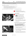
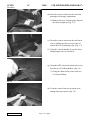
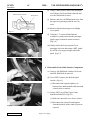
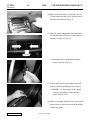
1
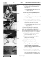
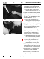
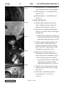
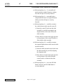
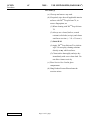
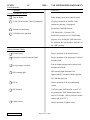
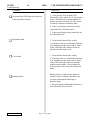
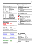
SCION
tC
VSE SUBWOOFER (BAZOOKA®)
2005 -
Preparation
NOTE: Part number of this accessory may not be
the same as the part number shown.
Part Number: PTS20-21050
Kit Contents
Item #
1
2
3
4
5
6
Quantity Reqd.
1
1
1
1
1
1
Description
Vehicle Specific Enclosure
(VSE) Subwoofer
Wire Harness
Hardware Bag
Installation Instructions
Product Feature Placard
Service Care Card
Quantity Reqd.
2
2
8
1
5
1
Description
7” Wire Ties
4” Wire Ties
Philips Head Screws
Upper Mounting Hardware
Assembly
Lower Mounting Hardware
Assembly
Additional Items Required For Installation
Item #
1
Quantity Reqd.
Description
SCION tC Cargo Net – PN: PT347-52051
Vehicle Protection
Part Protection
Notes
Seat/Floor Covers
Blankets
Special Tools
Notes
Arch Punch
5/8” Hole Diameter
(McMaster PN: 3427A17)
Rubber Mallet
1.5” Long Narrow Blade
Flat Head (Craftsman PN:
41541 or equivalent)
Mallet
Screwdriver
Installation Tools
Notes
Nylon Panel Removal Tool
e.g. Panel Pry Tool #1
Toyota SST # 00002-0600101
Socket/Ratchet
10mm, 12mm & 13mm
Socket Extension
6 inch (optional)
Ratcheting Box End Wrench 13mm
Torque Wrench
3 lbf·ft , and 15 lbf·ft
Pliers
Issue: A
1.
2.
04/15/04
Special Chemicals
Notes
Cleaner
3MTM Prep Solvent–70 (if
required)
General Applicability
ALL SCION tC
Item #
1
2
3
4
Accessory
Security / Audio / Satellite Tuner
Rear Cargo Mat / Cargo Liner
VSE Subwoofer
Door Sills
*Mandatory
Vehicle Service Parts (may be required for reassembly)
Item #
1
Quantity Reqd.
Description
Legend
Conflicts
Recommended Tools
Personal & Vehicle
Protection
Magnetized Philips # 2
Philips # 2 Drill Bit
Recommended Sequence of Application
Hardware Bag Contents
Item #
1
2
3
4
Screwdriver
Electric Drill
STOP: Damage to the vehicle may occur. Do not
proceed until process has been complied with.
OPERATOR SAFETY: Use caution to avoid risk of
injury.
CAUTION: A process that must be carefully observed
in order to reduce the risk of damage to the
accessory/vehicle and to ensure a quality installation.
TOOLS & EQUIPMENT: Used in Figures calls out the
specific tools and equipment recommended for this
process.
REVISION MARK: This mark highlights a change in
installation with respect to previous issue.
VSE Subwoofer Specifications
Woofer Size
Voice Coil Size
Magnet Size
Frequency Response
Efficiency
Power Handling
Dimensions
Weight
Impedance
Diagonal Cutters
Long Nose (optional)
Page 1 of 17 pages
10 Inch
1.5 Inch
34 oz
28Hz-100Hz +/-3dB
96 dB
150 watts (woofer)
745mm x 390mm x 370mm
22 lbs
Dual 2 Ohms
SCION
tC
VSE SUBWOOFER (BAZOOKA®)
2005 -
Procedure
Care must be taken when installing this accessory to ensure damage does not occur to the vehicle. The installation of this
accessory should follow approved guidelines to ensure a quality installation.
These guidelines can be found in the "Accessory Installation Practices" document.
This document covers such items as:• Vehicle Protection (use of covers and blankets, cleaning chemicals, etc.).
• Safety (eye protection, rechecking torque procedure, etc.).
• Vehicle Disassembly/Reassembly (panel removal, part storage, etc.).
• Electrical Component Disassembly/Reassembly (battery disconnection, connector removal, etc.).
Please see your Toyota dealer for a copy of this document.
1.
Pre-installation Precautions
(a) Use Seat & Floor Protectors and Fender
Covers/Blankets to avoid damage to surfaces.
2. Battery Disconnect
(a) NOTE: Be sure to open the rear hatch,
PRIOR to disconnecting the battery.
(b) For vehicles equipped with automatic
transmission, place the shifter in the N
(neutral) position and set the parking brake
prior to disconnecting the battery.
(c) Remove the NEGATIVE (-) battery terminal
using a 10mm socket before any disassembly
starts. (Fig. 2-1)
Fig. 2-1
3. Disassemble Rear Cabin Interior Components
NOTE: ALL INTERIOR COMPONENTS
THAT ARE REMOVED FROM THE
VEHICLE MUST BE PLACED ON A CLEAN
& PROTECTED SURFACE (i.e. Blanket)
(a) Starting at the rear of the vehicle, remove and
secure the rear Tonneau Cover.
(b) Proceed to unlock the two (2) knob locks and
remove and secure the rear Cargo Floor panel
& floor mat (if equipped).
(c) Proceed to remove and secure the rear cargo
entry scuff plate by pulling upwards.(Fig. 3-1)
Fig. 3-1
Issue: A
04/15/04
Page 2 of 17 pages
SCION
tC
VSE SUBWOOFER (BAZOOKA®)
2005 -
Procedure
(d) Proceed to remove and secure the rear foam
passenger side storage compartment.
(1) Remove the two (2) plastic plugs and pull
the block straight up. (Fig. 3-2)
Fig. 3-2
(e) Proceed to remove and secure the rear bench
seat, by pulling upwards on each corner, to
release the two (2) mounting clips. (Fig. 3-3)
(f) Using the 2 release handles, lower the driver
and passenger side rear seat backs.
Fig. 3-3
(g) Using the NRT, release the plastic bolt covers
from the two (2) D-Ring holders. (Fig. 3-4)
(1) Using the 10mm socket, remove the two
(2) 10mm D-Rings.
Fig. 3-4
(h) From the center of the rear seat trim cover,
unsnap and remove panel. (Fig. 3-5)
Fig. 3-5
Issue: A
04/15/04
Page 3 of 17 pages
SCION
tC
VSE SUBWOOFER (BAZOOKA®)
2005 -
Procedure
Release with Screwdriver
Plastic Hook
(i) Using a 10mm socket, remove the passenger
rear D-Ring (Tie Down Hook) (discard) and
save the 10mm bolt for reuse.
(j) Remove and save, the Philips head screw from
the upper rear passenger panel & save for
reuse.
(k) Remove & discard passenger rear taillight
access panel.
Fig. 3-6
(l) Using the 1.5” narrow blade flat head
screwdriver, gently insert into the passenger
plastic cargo net hook & rotate to remove.
(Fig.3-6)
(m) Gently release the lower portion of rear
passenger side trim, then using a NRT, gently
pry off the rear cargo passenger side inner
panel. (Fig.3-7)
Fig. 3-7
4. Disassemble Front Cabin Interior Components
(a) Unscrew OE Shift Knob Counter-Clockwise
until OE Shift Knob is removed.
(b) Use a NRT to remove the shift surround
console. (Fig.4-1)
Fig. 4-1
(1) Disconnect the cigarette lighter wire
harness from underneath the shift surround
console prior to removal.
(c) Using a NRT, pry off the Upper Center
Instrument Panel (IP). (Fig.4-2)
(1) Make sure the radio cover door is closed.
(2) Disconnect the center IP main harness
from the backside of the center IP prior to
removal.
Fig. 4-2
Issue: A
04/15/04
Page 4 of 17 pages
SCION
tC
VSE SUBWOOFER (BAZOOKA®)
2005 -
Procedure
(d) Remove the radio unit, by removing the two
(2) top 10mm nuts and two (2) bottom screws
from the radio bracket. (Fig.4-3)
(e) Open the glove compartment latch and press
the outside edges of the glove compartment
inwards, to remove. (Fig.4-4)
Fig. 4-3
Fig. 4-4
(1) Detach the glove compartment damper
prior to removal. (Fig.4-5)
Fig. 4-5
(f) Using a NRT, remove passenger front scuff
plate by carefully pulling upward. (Fig.4-6)
(1) NOTE: If a clip remains on the vehicle,
remove it and replace it back into the
plastic doorsill cover.
(g) Remove passenger kick panel by removing the
plastic screw (located near firewall) & pulling
out the kick panel.
Fig. 4-6
Issue: A
04/15/04
Page 5 of 17 pages
SCION
tC
VSE SUBWOOFER (BAZOOKA®)
2005 -
Procedure
Fig. 5-1
5. Routing Wire Harness
(a) Starting at the rear of the vehicle, route the pig
tail end underneath the rear strut
reinforcement access panel, and route towards
rear passenger side taillight. (Fig.5-1)
1
2
Fig. 5-2
3
(b) Using the 12mm socket, remove the #3 Child
Restraint bracket bolt, & re-install groud ring
underneath bracket. (Fig.5-2)
(1) Torque bolt to 15 lbf·ft
(c) Run the T-Harness portion of the W/H
forward between the passenger seat bracket
and inner wheel well. (Fig.5-3)
(d) From inside the back seat, route W/H behind
seat belt & tuck under the rear passenger
speaker / cup holder panel.
Fig. 5-3
(e) Using a NRT, remove the panel-fastening clip.
(Fig.5-4)
(1) Proceed to route the wire harness
underneath clip tab, and back underneath
panel, with the T-Harness portion of the
wire harness exiting at the passenger side
entry way.
(f) Route wire harness forward through existing
vehicle-accommodated clips.
Fig. 5-4
Issue: A
04/15/04
Page 6 of 17 pages
SCION
tC
VSE SUBWOOFER (BAZOOKA®)
2005 -
Procedure
Fig. 5-5
(g) Attach wire harness with one (1) 4” wire tie at
the junction plug located underneath kick
well. (Fig.5-5)
(1) Using the diagonal cutter pliers, clip the
4” wire tie. (Fig.5-5)
Fig. 5-6
(h) Route wire harness up behind the dash and
secure wire harness to the dash reinforcement
bar using (1) 7” wire tie.
(1) Using the diagonal cutter pliers, clip the 7”
wire tie. (Fig.5-6)
Fig. 5-7
(i) Route remaining wire harness towards radio
opening and attach harness to the vertical dash
reinforcement using one (1) 4” wire tie.
(1) Using the diagonal cutter pliers, clip the 4”
wire tie. (Fig.5-7)
6. Prepare VSE Subwoofer for Installation
Fig. 6-1
NOTE: ALL SUBWOOFER COMPONENTS
THAT ARE REMOVED MUST BE PLACED ON A
CLEAN & PROTECTED SURFACE (i.e. Blanket)
(a) Using a NRT, carefully remove the front
screen of the enclosure. (Fig.6-1)
(b) Remove the two (2) temporary shipping
Philips screws and discard.
FRONT WASHER
REAR WASHER
Fig. 7-1
(c) Carefully remove the 10” driver.
7. Modify Rear Inner Quarter Panel
FRONT
LOCK
NUT
REAR
LOCK
NUT
Fig. 7-2
(a) Prepare the upper hardware assembly by
removing the front lock nut & first front
washer (leaving the second front washer
installed). Then remove the back lock nut and
flat washer. (Fig.7-1)
(b) Install the hardware assembly through the
front side of the accommodation hole located
on the lower inner sheet metal panel; secure
the hardware assembly by fastening the back
Issue: A
04/15/04
Page 7 of 17 pages
SCION
tC
VSE SUBWOOFER (BAZOOKA®)
2005 -
Procedure
flat washer and lock nut using a 13mm
ratcheting box end wrench or socket from
behind the inner sheet metal panel. (Fig.7-2)
(1) Make sure antenna wire harness runs
underneath hardware assembly (Fig.7-2)
(c) With the upper hardware assembly installed,
index the outer rear quarter panel by
positioning panel over the hardware stud and
use the 5/8” Hole Punch & Mallet to punch a
hole through the panel. (Fig.7-3)
(1) NOTE: Make sure that the rear wire
harness Pigtail is routed out through the
rear taillight access hole of the panel.
Fig. 7-3
(d) Using a 10mm socket and the original D-Ring
bolt (Reference Step 3. j.), install the lower
hardware assembly over the panel onto the
original D-Ring location. (Fig.7-4)
8. Reassemble Rear Cabin Interior Components
(a) Referencing Step 3. k. - n., reassemble the rear
inner quarter panel, making sure that all
fasteners, clips, etc, are securely fastened.
Fig. 7-4
(1) The front portion of the rear inner quarter
panel will need to hook into the inside of
the rear cargo passenger side inner panel
(2) NOTE: Make sure that the rear wire
harness Pigtail is routed out through the
rear taillight access hole of the panel.
(b) Referencing Step 3. f. - i., reassemble the rear
seat panel & two D-Rings, making sure that
all fasteners, clips, etc, are securely fastened
(c) Referencing Step 3. d, reassemble the rear
passenger side storage compartment.
(d) Referencing Step 3. c, reassemble the rear
cargo entry scuff plate.
Issue: A
04/15/04
Page 8 of 17 pages
SCION
tC
VSE SUBWOOFER (BAZOOKA®)
2005 -
Procedure
(e) Referencing Step 3. b, reassemble the rear
Cargo Floor panel & floor mat (if equipped).
Fig. 9-1
(f) Referencing Step 3. a, reassemble the rear
Tonneau Cover.
(g) Referencing Step 3. e, reassemble the rear
bench seat.
9. Install VSE Subwoofer
Fig. 9-2
(a) With the pigtail exiting the inner quarter
panels’ taillight access hole, connect the
pigtail to the VSE Subwoofer. (Fig.9-1)
(b) Align the lower mounting stud through the
enclosures’ lower hole, followed by the upper
mounting stud.
Fig. 9-3
(1) Install the lower mounting assemblies’ flat
washer & locknut onto the lower mounting
stud, tighten using 10mm socket. (Fig.9-2)
(c) Install the upper mounting assemblies’ flat
washer (with EVA gasket facing quarter
panel) & lock nut onto the upper mounting
stud, & SECURELY tighten using a 13mm
ratcheting box end wrench. (Fig.9-2)
Fig. 9-4
(d) Reinstall 10” driver into enclosure, by
connecting the 4 speaker connectors to the
driver (any sequence is acceptable). (Fig.9-3)
(1) Once connectors have been connected,
align the holes of the driver with the holes
of the enclosure, and fasten with the
supplied 8 Philips head screws. (Fig.9-4)
Fig. 9-5
(e) Adjust the Gain Control knob to the factory
suggested position (indicated by the setting
dot). (Fig.9-5)
(f) NOTE: Only reinstall front grille after
completing Step 13 “Test & Set Up
Procedures”
Issue: A
04/15/04
Page 9 of 17 pages
SCION
tC
VSE SUBWOOFER (BAZOOKA®)
2005 -
Procedure
10. In Process Functional Test.
(a) Reconnect the vehicle’s negative battery
cable.
(1) Position the negative terminal at an angle
of 90˚ to the battery as shown.
(2) Tighten the nut with 4.1 N-m (36 lbf-in) of
torque.
(3) Be careful not to touch the positive battery
terminal.
(b) Referencing Step 4. d., reassemble the Radio
by connecting: 1) T-Harness into the back of
the Radio2) the Satellite harness (if equipped)
and 3) the radio antenna cable.
(1) Carefully insert Radio back into center IP
opening, by aligning mounting holes to the
radio bracket. Be sure the wire harness is
not pinched.
(2) Securely fasten (hand tighten) the four (4)
mounting fasteners using the 10mm socket
and #2 Philips Screwdriver. DO NOT
OVER TIGHTEN
(c) Turn ignition key to "ACC" position.
(d) Press the power button on the receiver/player
head unit. Verify the backlighting illuminates.
(e) Verify that the green led on the VSE is
illuminated, and that sound is coming out of
the driver.
NOTE: If the green light on the VSE unit is
illuminated, and there is no sound coming from
the driver –then one (or more) of the four (4)
speaker wires are disconnected.
NOTE: If the green light on the VSE unit is NOT
illuminated – then the wire harness is not
properly connected to either the radio/amplifier,
or is not properly grounded.
Issue: A
04/15/04
Page 10 of 17 pages
SCION
tC
VSE SUBWOOFER (BAZOOKA®)
2005 -
Procedure
11. Reassemble Front Cabin Interior Components
(a) Referencing Step 4. g - f., reassemble all
panels into their original locations, making
sure that all clips are securely fastened.
(b) Referencing Step 4. e., reassemble glove
compartment & strut to its original location,
making sure that all clips are securely
fastened.
(c) Referencing Step 4. c., carefully reconnect
the vehicle harness back onto the center IP.
(1) Insert the center IP back onto the dash
assembly by carefully inserting the top
alignment tabs of the center IP into the
dash assembly
(2) Once tabs are secured, then apply pressure
to the perimeter of the center IP until it is
flush with the dash assembly.
(d) Referencing Step 4. b., carefully reconnect
the cigarette lighter harness back onto the shift
surround console
(1) Insert the shift surround console back onto
the dash assembly by carefully aligning
the alignment tabs.
(2) Once tabs are secured, then apply pressure
to the perimeter of the shift surround
console until it is flush with the dash
assembly.
(e) Referencing Step 4. a., screw the OE Shift
Knob Clockwise until OE Shift Knob is
securely tightened.
Issue: A
04/15/04
Page 11 of 17 pages
SCION
tC
VSE SUBWOOFER (BAZOOKA®)
2005 -
Procedure
12. Resetting Vehicle Components
(a) Reset the power windows.
(1) Turn ignition key to ON position.
(2) Push down the power window switches of
each door, and lower the windows
halfway.
(3) Pull up the switches until the windows
close and hold switches up for a further
one (1) second (minimum.)
(b) Reset the power moon roof.
(1) Push and hold moon roof switch to close
side until moon roof closes. Hold for a
further two (2) seconds.
13. Test and Set Up Procedures
(a) If system is installed correctly, the VSE
Subwoofer will power up when the vehicle’s
ignition is turned on. (This can be confirmed
by the lighting of the POWER L.E.D. on the
Gain Control module of the unit.) (Fig.9-5)
(b) Using the tone controls on the radio, adjust the
balance left and right, to verify that VSE
Subwoofer produces sound on both sides, and
that the sound is loudest when the balance is
set to the center.
(c) Tune to a radio station or CD, and adjust
volume to a comfortable listening level. (If
the sound is distorted, adjust the gain control
knob counter-clockwise (-) until the VSE
Subwoofer produces clean sound. If the unit
cannot be heard, adjust the gain control
clockwise (+) until sufficient output is
achieved.)
(d) Carefully reinstall grille.
Issue: A
04/15/04
Page 12 of 17 pages
SCION
tC
VSE SUBWOOFER (BAZOOKA®)
2005 -
Procedure
14. Clean Up
(a) Clean up and remove any trash.
(b) If required, wipe down all applicable interior
surfaces with 3MTM Prep Solvent-70, to
remove fingerprints, etc
(1) When cleaning with 3MTM Prep Solvent70:
(2) Always use a clean (lint free, scratch
resistant) soft cloth (or wipe), and clean a
small area at a time ( ~ 3 ft. x 3 ft. max.).
(3) Shake Well.
(4) Apply 3MTM Prep Solvent-70 to cloth or
wipe. Do not spray cleaning solutions
directly to any vehicle surfaces.
(5) Clean surface thoroughly and wipe dry
immediately with a new clean cloth. Do
not allow cleaner to air dry.
(c) Place Service Care Card in glove
compartment
(d) Hang Product Feature Placard onto the
rearview mirror.
Issue: A
04/15/04
Page 13 of 17 pages
SCION
tC
2005 -
VSE SUBWOOFER (BAZOOKA®)
Troubleshooting.
Condition:
Check For:
Accessory Function Checks
Turn on Radio
Radio display turns on & sound is heard
Verify CD & Satellite Tuner (if equipped)
CD player functions & Satellite Tuner
stations are playing (if equipped)
Antenna is functioning
Reception of AM/FM stations
VSE Subwoofer operation
VSE Subwoofer – Listen to VSE
Subwoofer to make sure it is functioning
properly or by feeling the VSE Subwoofer
for vibration. Be sure the Phase Switch is in
the “UP” position.
Vehicle Function Checks
Hazard switch.
Proper operation of the hazard switch.
Passenger's seat belt reminder light.
Proper operation of the passenger's seat belt
reminder light
Seat in upright position and seat back lock
Rear passenger seat back.
mechanism secured.
SRS warning light illuminates for
SRS warning light.
approximately 6 seconds with the ignition
ON, and then goes out.
Proper operation of the air conditioning
HVAC.
system.
Verify the radio SSP function is set to "tC"
SSP function.
by pressing the "SSP" button on the head
unit for 5 seconds. (If not, press the volume
control and set to "tC".)
Lighter socket.
Issue: A
04/15/04
Proper operation of lighter socket.
Page 14 of 17 pages
SCION
tC
VSE SUBWOOFER (BAZOOKA®)
2005 -
Troubleshooting.
Condition:
Check For:
No sound from VSE Subwoofer, however
factory speakers still play
1. Is the green L.E.D. lit on the VSE
Subwoofer? If not, check for 12 volts on pins
of the VSE Subwoofer with the ignition on.
If either pin doesn’t indicate 12 volts, check
T-Harness connectors behind the radio.
2. Is the 14-pin Molex connector securely
connected to the VSE Subwoofer?
3. Is the ground ring securely fastened to the
rear anchorage bolt?
Distorted Sound
1. Close the back hatch of the vehicle
2. Adjust the radio to a comfortable listening
level, and then turn the “gain control” knob
on the VSE Subwoofer counter-clockwise
until the sound becomes clean.
Low Sound
1. Close the back hatch of the vehicle
2. Adjust the radio to a comfortable listening
level, and then turn the “gain control” knob
on the VSE Subwoofer clockwise until the
sound becomes audible. Do not adjust the
level too high, as this will result in distorted
sound.
Rattling Noises
Rattling will be evident in some panels at
extreme volume conditions, but make sure
you have performed the following to
minimize noise:
1. Securely tightened Mounting Hardware so
VSE Subwoofer does not move.
Issue: A
04/15/04
Page 15 of 17 pages
SCION
tC
VSE SUBWOOFER (BAZOOKA®)
2005 -
Troubleshooting.
Condition:
Check For:
Dimming Radio Lights
Dimming Radio Lights could occur when the
VSE Subwoofer is played at high volumes.
Radio does not come on
Check to ensure that the main connector,
antenna connector, and auxiliary connector
have been correctly plugged back in.
No Sound at all
1. Is the fuse under the hood still
operational?
2. Is the battery ground reconnected?
3. Is the radio connector securely seated?
VSE Subwoofer produces sound on the
right or the left, but not both.
Issue: A
04/15/04
Check T-Harness connections at the back of
the radio. All connectors must be securely
fastened to the correct wiring for both
channels to produce audio output.
Page 16 of 17 pages
SCION
tC
2005 -
VSE SUBWOOFER (BAZOOKA®)
Wire Harness & Radio Wiring Schematics.
WIRING CONNECTOR SCHEMATICS:
Harness Split
Pin No.
Wire Color
1
2
3
4
5
6
Red
White/Black
Gray/Black
Blue/White
White
Gray
Radio Connector
Subwoofer Connector
Harness Split Connector
Function
12 Volt Battery Connection (B+)
Left Front Speaker (-)
Right Front Speaker (-)
Remote Turn-On/Ignition (Switched+)
Left Front Speaker (+)
Right Front Speaker (+)
Subwoofer Connector
Pin No.
Wire Color
1
2
3
4
5
6
7
8
9
10
11
12
13
14
Black
N/A
N/A
N/A
White
Grey
N/A
Red
Blue/White
N/A
N/A
White/Black
Grey/Black
N/A
Pin No.
1
2
3
4
5
6
7
8
9
10
11
12
Issue: A
04/15/04
Function
Chassis Ground
N/A
N/A
N/A
Left Front Speaker (+)
Right Front Speaker (+)
N/A
12 Volt Battery Connection (B+)
Remote Turn-On/Ignition (Switched+)
N/A
N/A
Left Front Speaker (-)
Right Front Speaker (-)
N/A
Radio Connector (R4 GRAY)
Wire Color
Function
NO CONNECTION
NO CONNECTION
Right Front Speaker (+)
Left Front Speaker (+)
NO CONNECTION
NO CONNECTION
12 Volt Ignition Switched (B+)
12 Volt Battery Connection (B+)
Right Front Speaker (-)
Left Front Speaker (-)
Chassis Ground (B-)
Power Antenna Control (+)
Power Antenna Control (-)
Dimmer / Illumination Control (B+ variable)
Page 17 of 17 pages