1
Remote/Modular Data Acquisition
CyMOD™ Series
CM 4510
CM 4520
CM 4531
CM 4530
CM 4510: RS-422/485 Repeater Module
CM 4520: RS-232 to RS-485 Converter
CM 4531: RS-422/485 to RS-232 Remote Serial Device
CM 4530: USB to RS-232/422/485 Converter
USER’S MANUAL
VER. 3 • OCT 2002
&
No part of this manual may be reproduced without permission.
CyberResearch®, Inc.
www.cyberresearch.com
25 Business Park Dr., Branford, CT 06405 USA
203-483-8815 (9am to 5pm EST) FAX: 203-483-9024
©Copyright 2002
All Rights Reserved.
October 2002
The information in this document is subject to change without prior notice in order
to improve reliability, design, and function and does not represent a commitment
on the part of CyberResearch, Inc.
In no event will CyberResearch, Inc. be liable for direct, indirect, special,
incidental, or consequential damages arising out of the use of or inability to use
the product or documentation, even if advised of the possibility of such damages.
This document contains proprietary information protected by copyright. All rights
are reserved. No part of this manual may be reproduced by any mechanical,
electronic, or other means in any form without prior written permission of
CyberResearch, Inc.
TRADEMARKS
“CyberResearch,” “CM 4510,” “CM 4520,” “CM 4531,” and “CM 4530” are trademarks of CyberResearch, Inc. Other product names mentioned herein are used for
identification purposes only and may be trademarks and/or registered trademarks
of their respective companies.
• NOTICE •
CyberResearch, Inc. does not authorize any CyberResearch product for use in life
support systems, medical equipment, and/or medical devices without the written
approval of the President of CyberResearch, Inc. Life support devices and
systems are devices or systems which are intended for surgical implantation into
the body, or to support or sustain life and whose failure to perform can be
reasonably expected to result in injury. Other medical equipment includes devices
used for monitoring, data acquisition, modification, or notification purposes in
relation to life support, life sustaining, or vital statistic recording. CyberResearch
products are not designed with the components required, are not subject to
the testing required, and are not submitted to the certification required to ensure
a level of reliability appropriate for the treatment and diagnosis of humans.
Table of Contents
Chapter 1 Introduction.............................................................. 1
1.1
1.2
1.3
1.4
1.5
1.6
1.7
1.8
1.9.
1.10.
W HAT IS CYMOD?.........................................................................................1
OUTSTANDING FEATURES OF CYMOD .....................................................2
CYMOD 4000 SERIES PRODUCTS OVERVIEW ..............................................3
EIA RS-485 STANDARD ..................................................................................4
RS-485 ON CYMOD ........................................................................................4
CYMOD RS-485 NETWORK CONFIGURATIONS.........................................5
CONSTRUCTING A CYMOD NETWORK ......................................................8
TERMINATION BUS .........................................................................................8
SHIELDING........................................................................................................9
HOW TO CALCULATE CHECKSUM VALUE................................................10
Chapter 2 CYMOD 4520 .......................................................... 11
2.1.
2.2
2.3.
2.4
OVERVIEW ......................................................................................................11
SETUP ..............................................................................................................16
INSTALLATION ..............................................................................................18
PROGRAMMING ..............................................................................................19
Chapter 3 CYMOD 4510 .......................................................... 20
3.1.
3.2.
3.3
3.4
OVERVIEW ......................................................................................................20
SETUP ..............................................................................................................24
INSTALLATION ..............................................................................................26
PROGRAMMING ..............................................................................................27
Chapter 4 CYMOD 4530 .......................................................... 28
4.1.
4.2
4.3
4.4
OVERVIEW ......................................................................................................28
SETUP ..............................................................................................................33
INSTALLATION ..............................................................................................35
PROGRAMMING ..............................................................................................45
Chapter 5 CYMOD 4531.......................................................... 46
5.1.
5.2
5.3.
OVERVIEW ......................................................................................................46
INITIALIZTION & INSTALLATION...............................................................51
INSTALL A NEW CYMOD 4531 TO A EXISTING NETWORK ..................53
Table of Contents • i
5.4
COMMAND SET ..............................................................................................54
5.4.1 Command and Response ........................................................................... 54
5.4.2 Summary of Command Set......................................................................... 56
5.4.3 Set Configuration ....................................................................................... 57
5.4.4 Read Configuration ................................................................................... 60
5.4.5 Read Module Name .................................................................................... 61
5.4.6 Read Firmware Version............................................................................. 62
5.4.7 Soft Reset ...................................................................................................... 63
5.4.8 Reset Status.................................................................................................. 64
5.4.9 Set RTS Status ............................................................................................. 65
5.4.10 Read RTS Status ....................................................................................... 66
5.4.11 Read CTS Status....................................................................................... 67
5.4.12 Set Device ID ............................................................................................. 68
5.4.13 Read Device ID ......................................................................................... 69
5.4.14 Set Delimiter.............................................................................................. 70
5.4.15 Read Delimiter .......................................................................................... 71
5.4.16 Data Pass ................................................................................................... 72
5.4.17 Open/Close Data Gate ............................................................................ 73
5.4.18 Read Command Leading Code Setting........................................... 74
5.4.19 Change Command Leading Code Setting ........................................... 75
5.4.20 Set Host Watchdog Timer........................................................................ 77
5.4.21 Read Host Watchdog Timer .................................................................... 78
5.4.22 Host is OK .................................................................................................. 79
Chapter 6 Software Utility ...................................................... 80
6.1
SOFTWARE INSTALLATION.........................................................................80
6.2
HOW TO EXECUTE THE CYMOD A DMINISTRATION ............................80
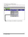
6.3
CYMOD A DMINISTRATION FUNCTION OVERVIEW...............................81
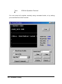
6.3.1 Change RS-232 Communication Port Setting..................................... 81
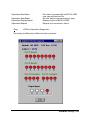
6.3.2 Search all exist CYMOD modules........................................................... 82
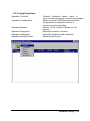
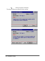
6.3.3 Using Operations........................................................................................ 83
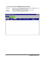
6.3.4 Save and Print CYMOD information ...................................................... 87
6.3.5 Version Information ...................................................................................88
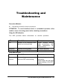
TROUBLESHOOTING AND MAINTENANCE.......................................................89
ii • Table of Contents
1
Introduction
1.1 What is CYMOD?
CYMOD is a series of data acquisition modules. It provides a total solution of
the data acquisition network and control system. You can remotely control up to
256 CYMOD modules on RS-485 netowrk. All you need is to use a host
computer, like a liPC (Personal Computer), with one RS-232 serial port for
controlling the whole system. The maximum communication distance is 4000
feet from the host computer.
CYMOD is based on the RS-485 multi -drop network system, each module has
an unique address ID. Using simple ASCII command & response protocol
through standard RS-485 interface can control all the CYMOD modules in the
RS-485 network.
The CYMOD modules provide direct linkage to a wide variety of sensors and
perform all signal conditioning, scaling, linearization and conversion. The
modules can be used to measure temperature, pressure, flow, voltage, current
and numerous types of digital signals.
Introduction • 1
1.2 Outstanding Features of CYMOD
l
Industry standard networking
All CYMOD modules use the RS-485 communication protocol for transmitting
and receiving at high rates and over long distance.
l
Two-wire and multi-drop communication
A single twisted pair of wires is used to transmit and receive data between
modules. Multi-drop capability makes system configuration more flexible and
makes it easy to set up a network.
l
High transfer speed
CYMOD modules provide up to 115.2K bps data / command transfer rate, which
can promote system bandwidth.
l
Simple command / response protocol
All communications are performed with printable ASCII characters. This
allows the information to be processed with string functions common to the
most high-level languages.
l
Industrial design
The screw terminal plug connectors on every CYMOD module ensure simple
installation and easy modification. The compact size allows the modules to be
mounted on DIN rail, back-panel wall-mount, etc.
l
Watch-dog supervisory
CYMOD contains a watch-dog supervisory circuitry that will automatically reset
the module when the system fails. In addition, a user-programmable s oftware
timer provides a "safe" output signal in the event of host computer failure.
l
High isolation voltage
CYMOD provides photo -isolators, which ensure high isolation voltage
between the data acquisition circuits and the communication port. The fatal
electric-shock won‘t go through and damage all the modules on the network.
l
Noise immunity
The CYMOD provide extra noise immunity capability. An electrode, which is
coated inside the ABS case, can reduce electro-magnetic interference (EMI)
and noise.
2 • Introduction
l
Harsh environmental protection
A surface coating covers on the PCB and electronic components of the CYMOD.
It allows superior resistance to harsh environment such as humidity, salt spray
and most harsh chemicals.
1.3 CYMOD 4000 Series products overview
The CYMOD 4000 series provides the complete sets of data acquisition
modules, including communication modules, analog input modules,
analog output modules, and digital I/O modules.
u
Communication Module
♦
♦
♦
♦
u
Analog Input Modules
♦
♦
♦
♦
♦
♦
♦
♦
u
CM 4011: Multifunction High Gain Analog Input Module(with
DI/O)
CM 4011D: Multifunction High Gain Analog Input with 5 ½ digit
LED Display(with DI/O)
CM 4012: Analog Input Module(with DI/O)
CM 4012D: Analog Input Module with 5 1/2 digit LED
Display(with DI/O)
CM 4013A: 3 -channel RTD Input Module
CM 4014D: Analog (Transmitter) Input Module with 5 1/2digit
LED Display
CM 4017: 8 -channel Analog Input Module
CM 4018: 8 -channel Thermocouple Input Module
Analog Output Modules
♦
♦
u
CM 4510: RS-422/RS-485 Repeater
CM 4520: RS-232 to RS-422/RS-485 Converter
CM 4530: USB to RS-422/RS-485 Converter
CM 4531: Addressable RS-422/RS-485 to RS-232 Converter
CM 4021: Single Channel Analog Output Module
CM 4024: 4 -channel Analog Output Module(with DI)
Digital I/O Modules
♦
♦
♦
♦
♦
CM 4050: Module with 7 DI channels and 8 DO channels
CM 4052: Isolated Digital Input Module
CM 4053: 16-channel digital Input Module
CM 4054: 15-channel digital Input Module
CM 4056: 15-channel digital Output Module
Introduction • 3
♦
♦
♦
♦
CM 4058: 28-channel programable digital I/O Module
CM 4060: 4 -channel Relay Output & Digital Input Module
CM 4063: 8 -channel Relay Output Module
CM 4080: Counter/Frequency Input Module
1.4 EIA RS-485 Standard
The EIA RS-485 interface is a communication standard developed for
multi-dropped systems that can communicate at high rate over long distance.
The standard RS-485 can operate at speed up to 10 M bps over cable length up
to 4000 feet.
The RS-485 interface can support up to 32 drivers/receivers on the same line.
This allows actual networking applications on a parity line system (sometimes
called multi -drop).
The RS-485 uses differential transmission on a balance line. Its easy wiring
make it popular to use in industrial applications .
1.5 RS-485 on CYMOD
The CYMOD improves the RS-485 capability for minimizing the user's cost. On
each CYMOD module, a half-duplex RS-485 transceiver is used to
communicate with other modules. A single twisted pair of wires, which
provides standard differential transmission, is used to transmit and receive
data between modules. The high input impedance of each CYMOD receiver
allows up to 128 CYMOD modules on the same RS-485 bus without using a
signal repeater.
The maximum transfer rate of CYMOD is 115.2 Kbps which is lower than the
maximum speed of the RS-485 standard. The slew-rate limiter on every
RS-485 transceiver of CYMOD is very useful for transmitting error-free data,
minimizing EMI, and reducing reflections caused by improperly terminated
cables.
The CYMOD on a network may not use the same power supply. Therefore, the
voltage difference between ground of the modules may exist.
Excessive output current and power dissipation caused by faults or by bus
contention are prevented by the current limiter and the thermal shutdown
circuitry inside the CYMOD.
4 • Introduction
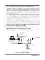
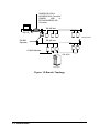
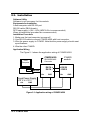
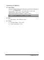
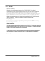
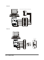
1.6 CYMOD RS-485 Network Configurations
CYMOD 400 Series is designed under RS-485 multi -drop network
architecture. Up to 256 CYMOD modules can be controlled in a multi -drop
network. The limit of 256 is due to command code. The network can be
connected by simple topology (Figure 1-1) or branch topology (Figure 1-2) or
free topology (Figure 1-3).
The CM 4520 and CM 4510 are the two basic communication modules to
construct a RS-485 network. The CM 4520 is a RS-232 to RS-485/RS-422
converter. The CM 4520 is used to build a RS-485 port for the host computer by
converting standard RS-232 signal into RS-485 signal.
The CM 4510 is the RS-485 signal repeater which is used to extend or to
lengthen the network distance. A CYMOD bus can connect up to 256 modules,
each segment is up to 128 modules. Whenever the numbers of the modules
excess 128, the repeater should be used. In addition, the length of a standard
RS-485 bus is up to 4000 feet, the repeater should be used whenever the
length of a signal bus is more than 4000 feet.
The CM 4530 is the USB to RS-485/RS-422/RS-232 converter, and it used to
build the USB signal into RS-485/RS-422/RS-232 signal.
The CM 4524 is an addressable RS-485/RS-422 to RS-232 converter, it allows
the RS-232 devices to easily link to the Host by the RS-485/422 bus.
CM 4520: RS -232 to
RS-485/RS-422
RS-232/RS-485 Converter
CM 4530 USB
to
RS-232/RS485/RS-422
Converter.
RS-485 bus
Host
Terminator
RS-232
CYMOD Modules
CM 4524
Figure 1-1 Simple Topology
Introduction • 5
CM 4520: RS -232 to
RS-485/RS-422 Converter
CM 4530:
USB
to
RS-232/RS485/RS-422
Converter.
Host
RS-485 bus
RS-232
Terminator
CM 4520
Repeater
RS-485 bus
CYMOD Modules
CM 4531
Figure 1-2 Branch Topology
6 • Introduction
CM 4520: RS -232 to
RS-485/RS-422 Converter
CM 4530:
USB
to CYMOD Modules
RS-232/RS485/RS-422
Converter.
Terminator
Host
RS-485 bus
CM 4510
Repeater
CM 4510
Repeater
Terminator
CM 4531
Terminator
CYMOD I/O modules
CYMOD I/O modules
Figure 1-3 Free Topology
Introduction • 7
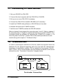
1.7 Constructing a CYMOD Network
1. Set up a CM 4520 or CM 4530.
2. Connect the host computer with the CM 4520 or CM 4530.
3. Set up one or more CM 4510 if necessary.
4. Connect the CM 4510 to extend to RS-485 bus if necessary.
5. Install the CYMOD utility software or CM 4530 driver from disk.
6. Initialize the brand-new CYMOD modules.
7. Add the new CYMOD modules into RS-485 network.
Refer to chapter 2 and chapter 4 for executing step 1 and 2. Refer to chapter 3
for executing step 3. Chapter 4 explains the best time to install CM 4510. The
information about the software for operating the CYMOD is in chapter 6. For
executing step 6 and step 7, please refer to the install procedures of each
module along with chapter 6, "Software Utility."
1.8 Termination Bus
In order to avoid signal reflections on the bus, each bus segment has to be
blanked off at its physical beginning and at its end with the characteristic
impedance. A termination resister ( Rt) is intalled for this purpose. The Rt
value - 120Ω ± 2% is recommended, and the detailed connection of Rt can be
referred from the “Terminator Connection” diagram below.
Host
Data+
Data+
120 ohms
Data-
120 ohms
Data-
Terminator Connection
8 • Introduction
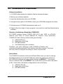
1.9. Shielding
In case of increased interference, shielded bus cables are recommended
for both intra and inter-module wiring . In addition, shielding should
also be employed for power supply and signal cables.
Shielding Recommendations:
1. The shield should be connected with protective grounding at each bus
connection.
2. The shield should be applied several times along the course of
the cable.
3. The shield should be applied directly to the computer, or to separate shield
rails.
braided shield
Grounding Point
Isolation
DATA -
DATA+
RS-485 Connection Cable
CYMOD Module
Introduction • 9
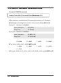
1.10. How to Calculate Checksum Value
Format of CYMOD Commands
(LeadingCode)(Addr)(Command)(Data)[Checksum]<CR>
When checksum is enable then [Checksum] is needed, it is 2 -character.
[Checksum] = ((LeadingCode)+(Addr)+(Command)+(Data)) MOD 0x100
Example 1: checksum is disabled
User Command :
$012<CR>
Response
!01400600
:
Example 2: checksum is enabled
User Command :
$012B7<CR>
Response
!01400600AC
‘$’ = 0x24
:
‘0’ = 0x30
‘1’ = 0x31
‘2’ = 0x30
‘1’ = 0x31
‘4’ = 0x34
B7 = ( 0x24 + 0x30 + 0x31 + 0x32 ) MOD 0x100
‘!’ = 0x24
‘0’ = 0x30
‘6’ = 0x36
AC= ( 0x24+ 0x30+ 0x31+ 0x34+ 0x30+ 0x30+ 0x36+ 0x30+ 0x30) MOD 0x100
10 • Introduction
2
CYMOD 4520
2.1. Overview
What is CYMOD 6520 ?
CYMOD 4520 is a RS-232 to RS-422/RS-485 converter, it converts the RS-232
signal to the RS-422/RS-485 signals. The CM 4520 can be considered an
extension RS-422/RS-485 serial port for the host computer. A standard 9-pin
D-type connector is used to connect the host computer and the CM 4520.
Hence, the CM 4520 can connect with all kinds of PCs, IPCs or Notebook PCs,
which employ a standard RS-232 interface.
u
Features of CYMOD 4520
♦
♦
♦
♦
♦
♦
♦
♦
♦
RS-422/RS-485 transceiver
Differenial 2-wire half-duplex RS-485
Easy setup and installation
Auto direction flow control
Maximum 128 CYMOD on a bus without using repeaters
Maximum 256 addressable CYMOD modules
High transfer speed
High isolation voltage
Lower power consumption
CYMOD 4520 • 11
Specifications of CYMOD 4520
u
Input
♦
♦
♦
u
Output
♦
♦
♦
u
Isolation voltage : 5000 Vrms(between RS-422/RS-485 network
and host computer)
Bus
♦
♦
u
Interface :RS-485, differential, 2 half-duplex wires RS-422,
differential, 4 full-duplex wires
Speed (bps) : 1200(115.2K1), 2400, 4800, 9600, 19.2K, 38.4K, RTS
Max RS-485 network bus distance : 4000 ft. (1200m)
Isolation
♦
u
Interface : standard RS-232 9-pin female D -type connector
Speed (bps) : 1200(115.2K1), 2400, 4800, 9600, 19.2K, 38.4K, RTS
Data Format : 9 bits, 10 bits, 11 bits, or 12 bits
Max loading : 128 CYMODs on a RS-485 network
Max modules : 256 CYMODs with one CM 4510 repeater
Power
♦
♦
Power Supply : +10V to +30V
Power Consumption : 0.95 W
Note 1: 115.2K is supported by Firmware version A1.2 or later.
12 • CYMOD 4520
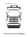
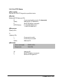
A Look at CYMOD 4520 & Pin Assignment
(RS-232 IN)
RS-232 to RS-485
(B)GND
TX-
RX+
TX-
RTS CTRL
115.2K bps
2400 bps
4800 bps
9600 bps
19.2K bps
38.4K bps
TX+
Baud Rate
SW1: ON
SW2: ON
SW3: ON
SW4: ON
SW5: ON
SW6: ON
SW7: ON
(R)+Vs
/RS-422 Converter
Switch Position
(G)DATA-
(Y) DATA+
CM 4520
CYMOD 4520 • 13
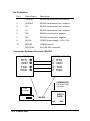
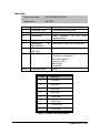
Pin Definitions
Pin #
Signal Name
Description
1
(Y)DATA+
RS-485 transmission line, positive
2
(G)DATA-
RS-485 transmission line, negative
4
TX+
RS-422 transmission line, positive
5
TX-
RS-422 transmission line, negative
6
RX+
RS-422 receiving line, positive
7
RX-
RS-422 receiving line, negative
9
(R)+VS
CYMOD power supply, +10V~+30V
10
(B)GND
CYMOD ground
--
RS-232 IN
9-pin RS-232 connector
Connection Between Host and CM 4520
Host RS-232
RTS
GND
TXD
RXD
CM 4520 RS -232
’
•
Ž
•
‡
…
ƒ
‚
RTS
GND
TXD
RXD
CYMOD 4520
RS-232/RS-485
Converter
Host
Computer
DATA +
DATA -
RS-232
+Vs
14 • CYMOD 4520
GND
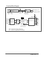
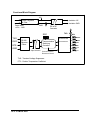
Functional Block Diagram
+5V
Isolation +5V
Power Regulator
& Filter
Power Input
+10V ~ +30V
Isolation GND
GND
DC to DC
Converter
SW1
RTS
PTC
Data+
TXD
RXD
TVS
RS-422/RS-485
RS-232
Receiver
/ Driver
Communication
Switching
Controller
GND
DataReceiver/Driver
Rx+
RxTx+
Opto-Isolation
Communication
Tx-
Direction Control
TVS : Transient Voltage Suppresser
PTC : Positive Temperature Coefficient
CYMOD 4520 • 15
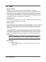
2.2 Setup
Objective of Setup
Normally, it is not necessary to setup the CYMOD 4520. The default
configuration of this communication module is 9600 bps, and data format of 8
data bits with 1 start bit, 1 stop bit, and no parity check. Note that the data format
is reserved to be compatible with other brand's communication port; it should
not be modified if only CYMODs are used in a system. The baud rate can be
configured according to the application's requirement.
Setup Equipment
A screw driver is necessary to open the case. Software, power supply, and wiring
require no additional installation equipment.
Setup Procedure
Only the hardware switch setting can be setup in CM 4520. The user can set the
speed of the serial interface ( RS-232 and RS-422/RS-485 ), and the serial
data format. The speed and the data format on the entire RS-485 network must
be identical.
To setup the CM 4520, use the screw driver to open the case, then change the
switch setting. The new setting is available after power up. The cover must be
re-installed and locked carefully. Do not scratch the surface of the circuit while
setting it up, otherwise the surface coating or the circuits themselves can
be damaged.
(Note: For Harware Rev.C1 or later, there is switchless baud rate
adjustment; the baud rate, parity and data bits adjust automatically.)
Default Setting
♦
♦
9600 baud rate
10 bits series data format : one start bit, eight data bits, one stop bit,
no parity check
16 • CYMOD 4520
SW1 Setting
SW1 Default Setting (9600 bps)
ON
OFF 1
1
ON
OFF
OFF
OFF
OFF
OFF
OFF
2
OFF
ON
OFF
OFF
OFF
OFF
OFF
3
OFF
OFF
ON
OFF
OFF
OFF
OFF
2
3
4
4
OFF
OFF
OFF
ON
OFF
OFF
OFF
5
OFF
OFF
OFF
OFF
ON
OFF
OFF
5
6
OFF
OFF
OFF
OFF
OFF
ON
OFF
6
7
OFF
OFF
OFF
OFF
OFF
OFF
ON
7
Baud Rate
RTS Control
1200 or 115.2k1 bps
2400 bps
4800 bps
9600 bps
19200 bps
38400 bps
Note 1: 115.2kbps is supported by version A1.2 or later.
SW2 Setting
SW2 Default Setting
ON
Start Bits : 1
Data Bits : 8
S t o p Bits : 1
Parity : None
OFF
1
OFF
2
OFF
OFF
ON
ON
OFF
ON
ON
1
2
Start Bit
1
1
1
1
1
1
1
1
Data Bits
7
6
8
7
9
8
10
9
Stop Bit
1
1
1
1
1
1
1
1
Parity
0
1
0
1
0
1
0
1
Packet Data Bits
9
10
11
12
CYMOD 4520 • 17
2.3. Installation
Software Utility
Software is not necessary for this module.
Equipments for Installation
A host computer with RS-232 port
RS-232 cable (DB-9 female)
DC Power supply (+10V~+30V) (NDP-243u is recommended)
Wires (shielded and grounded are recommended)
Installation Procedure
1. Make sure the host computer is power off.
2. Use RS-232 cable to connect CYMOD 4520 with host computer.
3. Wire the power supply to CYMOD. Note that the power supply should meet
specifications.
4. Wire the other CYMOD.
Application Wiring
The Figure 2 -1 shows the application wiring of CYMOD 4520.
CYMOD 4520
CYMOD
module
RS-232/RS-485
Converter
Host
Computer
DATA +
DATA -
RS-232
+Vs
GND
+ DATA
- DATA
+Vs
Local Power Supply
+10 V to +30 V
+Vs
GND
Figure 2 -1 Application wiring of CYMOD 4520
18 • CYMOD 4520
GND
2.4 Programming
The CYMOD 4520 is a communication module, it does not have to be
programmed.
CYMOD 4520 • 19
3
CYMOD 4510
3.1. Overview
What is the CYMOD 4510?
The CM 4510 is the RS-422/RS-485 signal repeater used to extend or
to lengthen the network distance. A CYMOD bus can connect up to 128
modules. The repeater should be used when module numbers
exceed 128. In addition, the repeater should also be used when the length of a
signal bus is more than 4000 feet.
Features of CYMOD 4510
l
RS-422/RS-485 signal transceiver & repeater
l
Bi-directions signal transmission for both RS-422/RS-485 ports
l
Automatic transmission direction control
l
Easy setup and installation
l
Maximum 128 CYMOD on a bus
l
Maximum 256 addressable CYMOD modules
l
High transfer speed
l
Surge protection
l
Lower power consumption
20 • CYMOD 4510
Specifications of CYMOD 4510
u
Input / Output
♦ Interface : RS-485, differential 2 half-duplex wires RS-422, differential, 4
full-duplex wires
♦ Speed (bps) : 1200(115.2K1) , 2400, 4800, 9600, 19.2K, 38.4K
♦ Data Format : 9 bits, 10 bits, 11 bits, or 12 bits
♦ Max RS-485 network bus distance : 4000 ft. (1200m)
Note 1: 115.2k is supported by version A1.2 or later.
u
Bus
♦
u
Max Loading : 128 CYMODs on a bus
Power
♦
♦
DC Power Supply : +10V to +30V
Power Consumption : 0.9 W
CYMOD 4510 • 21
11
Rx-
Rx+
Tx-
Tx+
DATA- (G)
DATA+ (Y)
20
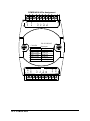
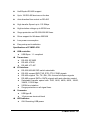
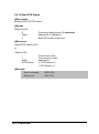
CYMOD 4510 & Pin Assignment
22 • CYMOD 4510
10
(B)GND
(R)+Vs
RX-
Rx+
115.2K bps
2400 bps
4800 bps
9600 bps
19.2 K bps
38.4 K bps
Tx-
Baud Rate
SW1-1: ON
SW1-2: ON
SW1-3: ON
SW1-4: ON
SW1-5: ON
SW1-6: ON
Tx+
Repeapter
Switch Position
(G)DATA-
1
(Y)DATA+
RS-422/RS-485
CM 4510
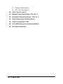
Pin Definitions
Pin #
1
2
4
5
6
7
9
10
14
15
16
17
19
20
Signal Name
(Y)DATA+
(G)DATATXIN+
TXINRXOUT+
RXOUT(R)+VS
(B)GND
RXINRXIN+
TXOUTTXOUT+
(G)DATA(Y)DATA+
Description
RS-485 transmission line, positive
RS-485 transmission line, negative
RS-422 transmission input line, positive
RS-422 transmission input line, negative
RS-422 receiving output line, positive
RS-422 receiving output line, negative
CYMOD power supply, +10V~+30V
CYMOD ground
RS-422 receiving input line, negative
RS-422 receiving input line, positive
RS-422 transmission output line, negative
RS-422 transmission output line, positive
RS-485 transmission line, negative
RS-485 transmission line, positive
CM 4510 Functional Block Diagram
+5V
Power Input
+10V ~ +30V
Power Regulator
& Filter
GND
SW1
TVS
Data+
Data+
RS-422/RS-485
DataRx+
Rx-
Receiver/Driver
RS-422/RS-485
Communication
Switching
Controller
Receiver/Driver
DataRx+
RxTx+
Tx+
Tx-
PTC
Communication
Direction
Control
Tx-
TVS : Transient Voltage Suppresser
PTC : Positive Temperature Coefficient
CYMOD 4510 • 23
3.2. Setup
Objective of Setup
Normally, the CYMOD 4510 only needs to be set up when the CYMOD
bus exceeds 128 modules, or the bus distance exceeds 4000 feet. The
default configuration of this communication module is 9600 bps and data
format of 8 data bits with 1 start bit, 1 stop bit, and no parity check. Note that the
data format is reserved to be compatible with other brand's communication
ports, it should not be modified if only the CYMOD brand is used in a system.
The baud rate can be configured according user’s requirement.
Setup Equipment
Only screw driver is used to open the case. Software, power supply, and wiring
do not require additional installation equipment.
Setup Procedure
Only the hardware switch setting can be setup in CM 4510. The user can set the
speed and the data format of the RS-422/RS-485 interface. The speed and the
data format on the entire network must be identical.
To set up the CM 4510, use the screw driver to open the case, then change the
switch setting. The new setting is available after power up. The case must be
re-installed and locked carefully. Do not scratch the surface of the circuit while
setting it up; the surface coating or even the circuits may be damaged as a
result.
(Note: For Harware Rev.C1 or later, there is switchless baud rate
adjustment; the baud rate, parity, and data bits adjust automatically.)
Default Setting
♦
♦
9600 Baud rate
10 bits serial data format : one start bit, eight data bits, one stop bit,
no parity check
24 • CYMOD 4510
SW1 Setting
SW1 Default Setting (9600 bps)
ON
OFF 1
1
ON
OFF
OFF
OFF
OFF
OFF
2
OFF
ON
OFF
OFF
OFF
OFF
2
3
OFF
OFF
ON
OFF
OFF
OFF
3
4
OFF
OFF
OFF
ON
OFF
OFF
4
5
5
OFF
OFF
OFF
OFF
ON
OFF
6
6
OFF
OFF
OFF
OFF
OFF
ON
Baud Rate
1200 or 115.2k1 bps
2400 bps
4800 bps
9600 bps
19200 bps
38400 bps
Note 1: 115.2kbps is supported by version A1.2 or later.
SW2 Setting
SW2 Default Setting
ON
Start Bits : 1
Data Bits : 8
S t o p Bits : 1
Parity : None
OFF 1
1
OFF
2
OFF
OFF
ON
ON
OFF
ON
ON
Start Bit
1
1
1
1
1
1
1
1
2
Data Bits
7
6
8
7
9
8
10
9
Stop Bit
1
1
1
1
1
1
1
1
Parity
0
1
0
1
0
1
0
1
Packet Data Bits
9
10
11
12
CYMOD 4510 • 25
3.3 Installation
Software Utility
Software is not necessary.
Equipments for Installation
A 2-wire RS-485 network or 4-wire RS-422 network.
DC Power supply (+10V~+30V)
Wires
Installation Procedure
1. Make sure the original RS-422/RS-485 network is powered off.
2. Wire the power supply to CYMOD 4510. Note that the power supply should
meet the specifications.
3. Wire other CYMODs to the extended RS-485 bus.
26 • CYMOD 4510
Application Wiring
CYMOD
module
CYMOD 4510
Repeater
DATA +
DATA +Vs
+DATA
-DATA
GND
+Vs
DATA+
DATAGND
CYMOD
module
+ DATA
- DATA
+Vs
GND
Local Power Supply
+10 V to +30 V
+Vs
GND
Figure 3 -1 CYMOD 4510 wiring.
3.4 Programming
The CYMOD 4510 is a communication module, it does not have to
be programmed.
CYMOD 4510 • 27
4
CYMOD 4530
4.1. Overview
What is CYMOD 4530 ?
Universal Serial Bus (USB) is an open, royalty free, Plug and Play standard for
PC
peripheral
connectivity,
supported
by
leading
computer,
telecommunications and software companies. It behaves i n a similar fashion to
conventional bus technology (serial, parallel, ISA… ), but it is faster, and requires
no additional slots or IRQs.
The CM 4530 takes advantages of the USB technology, and for the
convenience of PC, IPC, notebooks, laptops and handheld OC users,
it provides an easy way to link up with industry standard buses, interfacing with
RS-232/422/485 standards.
Features of CYMOD 4530
l
USB Specification 1.1 Compliant
l
Plug and Play Installation
l
Requires no AC outlet
l
RS-232 support RTS CTS handshake signal
l
Full-Duplex RS-422 support
28 • CYMOD 4530
l
Half-Duplex RS-485 support
l
Up to 128 RS-485 devices on the bus
l
Auto direction flow control on RS-485
l
High transfer Speed up to 115.2Kbps
l
High isolation voltage up to 2500Vrms
l
Surge protection on RS-232/422/485 lines
l
Driver support for Windows 2000/98
l
Low power consumption
l
Easy setup and installation
Specifications of CYMOD 4530
u
USB controller:
♦
u
Transceiver:
♦
♦
♦
u
♦
♦
RS-232/422/485 DIP switch selectable
RS-232 support RXD, TXD, RTS, CTS, FGND signals
RS-422 support TX+, TX-, RX+, RX- 4 wires full-duplex signals
RS-485 support DATA+, DATA- signals with auto direction control
Selectable transfer speed with 1200, 2400, 4800, 9600, 19200,
38400, 115200 bps
2500Vrms isolation
Surge protection on all signal lines
Connector:
♦
♦
u
RS-232: SP385E
RS-422: LT490
RS-485: LT1487
I/O Interface:
♦
♦
♦
♦
♦
u
USB Spec. 1.1 compliant
USB type B
10 pin screw terminal block
LED Indicator:
♦
ON: Receiving USB power
CYMOD 4530 • 29
♦
♦
Flashing: Data transfer
OFF: No power applied
u
Cable: Type A to type B
u
Storage Temperature Range: -25 to 80 ° C
u
Operating Temperature Range: -10 to 70 ° C
u
Power Requirement: USB bus power
u
Power Consumption: 0.6W
u
Case: ABS with captive mounting hardware
u
CE Class A Conformity
30 • CYMOD 4530
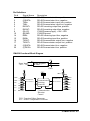
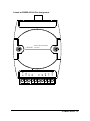
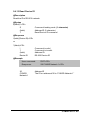
A Look at CYMOD 4510 & Pin Assignment
USB to RS-232/422/485
FGND
CTS
RTS
RX
TX
RX-
RX+
TX-/D-
TX+/D+
CM 4530 Converter
CYMOD 4530 • 31
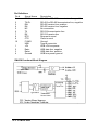
Pin Definitions
Pin #
1
2
3
4
5
6
7
8
9
10
1
2
3
4
Signal Name
TX+/D+
TX-/DRX+
RXNC
TX
RX
RTS
CTS
F.GND
USB
+5V
DataData+
Ground
Description
RS-422 or RS-485 transmission line, positive
RS-422 or RS-485 transmission line, negative
RS-422 receive line, positive
RS-422 receive line, negative
No connection
RS-232 transmission line
RS-232 receive line
Request to send
Clear to send
Ground
Type B connector
USB +5V bus power
USB data line, negative
USB data line, positive
USB bus power ground
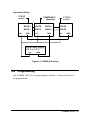
CM 4530 Functional Block Diagram
32 • CYMOD 4530
4.2 Setup
Objective of Setup
Normally, it is not necessary to set up the CYMOD 4520. The default
configuration of this communication module is in RS-485 mode, supporting
a baud rate of 75 to 115200, with data format including 5, 6, 7, 8 or 16 bits.
Its stop bit support 1, 1.5 or 2 bits, parity types are None, Odd, Even, Mark and
Space. Note that the data format is reserved to be compatible with other
brand's communication ports, it should not be modified if only CYMOD brand is
used in a system. There is no need to configure the baud rate.
Setup Equipment
A screw driver is needed to adjust the dip switch (next to the USB connector)
for protocol type selection.
Setup Procedure
Only the hardware switch setting can be set up in CM 4530. The user can select the
protocol types from the RS-422, RS-485 or RS-232 interface. The speed and data
format on the entire network must be identical.
To set up the CM 4530, use the screw driver to adjust the dip switch beside the
USB connector to select the protocol type. The new setting is available at
power up.
CYMOD 4530 • 33
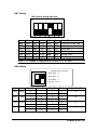
Default Setting
l
RS-485 Interface
DIP Switch Setting
RS-485 (Default)
RS-422
RS-232
34 • CYMOD 4530
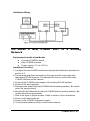
4.3 Installation
Software Utility
Install the CM 4530 Driver from the installation CD.
Equipments for Installation
A computer with USB port
Window 98 or Win2000 operation system
USB host controller installed on the system
USB cable (type A to type B)
u
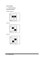
Windows 98 Installation:
1. Plug the CM 4530 into the computer USB port or a USB hub. The New
Hardware Wizard appears, click on Next to continue.
CYMOD 4530 • 35
2. In the dialog box that comes up, leave the default choice (Search for the best
drivers for your device), click on Next to continue.
3. In the dialog box that comes up, select the CD-ROM check box, and
click on Next to continue.
36 • CYMOD 4530
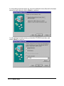
4. In the dialog box that appears click Next to continue.
5. When the dialog box appears with the Cyber USB driver displayed as the preferred
device driver, click Next.
6. When the PC copies the flies over to its hard drive successfully, click Finish.
CYMOD 4530 • 37
Installation Complete:
Now you have installed CM 4530 on your system. You will see a new USB
serial device in Control à Device Manager. The CM 4530 plays a role as
standard COM port, you can use any UART serial communication utility (eg.
HyperTerminal), or call standard windows API for COM.
38 • CYMOD 4530
u
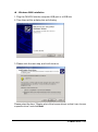
Windows 2000 Installation
1. Plug the CM 4530 into the computer USB port or a USB hub
2. Then there will be a dialog box as following
3. Please click the next step, and it will show as
Please select the item “Display a list of the known drivers so that I can choose
a specific driver" and click Next.
CYMOD 4530 • 39
4. When the Hardware Type dialog box appears, choose the item “Com &
LPT.” Then click Next
And please choose the device as following
40 • CYMOD 4530
5. Choose the driver called Cyber USB-to-Serial Com Port.
6. A dialog box will then appear with instruction that the selected device driver
is ready to be installed. Click the Next button.
7. You can now install the CM 4530 on your host.
CYMOD 4530 • 41
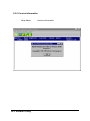
7. To check if the installation is success, please check the device in your device
manager, and there should be a device as
42 • CYMOD 4530
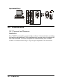
Application Wiring
RS-485
For RS-485 Transmission Distance Up to 1,200m (4,000 ft.)
Load more than 128 CYMOD I/O modules or more than 32
others RS-485 devices
DATA+
DATA-
RS-485 Device
ND-653 0
DATA+
DATA+
DATA-
DATA-
DATA+
DATA+
DATA-
DATA-
.....
.....
CYMOD 4530 • 43
RS-422
ForRS-422TransmissionDistanceUpto1,200m(4,000ft.)
TXTX+
RXRX+
ND-6 53 0
TX+
RX+
TX-
RX-
RX+
TX+
RX-
TX-
RS-232
RS-232 Device
TX
N D -6 530
RX
CTS
RTS
RTS
CTS
FGND
44 • CYMOD 4530
6
7
8
9
1
2
3
4
5
TXD
RXD
GND
4.4 Programming
The CYMOD 4530 is a communication module, it does not have to
be programmed.
CYMOD 4530 • 45
5
CYMOD 4531
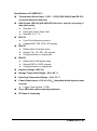
5.1. Overview
What is CYMOD 4531?
CYMOD 4531 is an RS-422/485 to RS-232 converter. It converts the
RS-422/485 communication signal to the RS-232 signals which allows
RS-232 devices to link up to R S-422/485 multi -drop networks.
Features of CYMOD 4531
l
l
l
l
l
l
l
l
l
l
l
l
l
RS-422/RS-485 transceiver
RS-232 support RTS CTS handshake signal
RS-232 and RS-422/485 can be different baud rate
Full-Duplex RS-422 support
Half-Duplex RS-485 support
Up to 128 RS-485 devices on the bus
Auto direction flow control on RS-485
Addressable and non-addressable mode configurable
High transfer Speed up to 115.2Kbps
High isolation voltage up to 2500Vrms
Surge protection on RS-422/485 lines
Low power consumption
Easy setup and installation
46 • CYMOD 4531
Specifications of CYMOD 4531
u
Transmission Speed (bps): 1,200 ~ 115,200 (RS-422/485 and RS-232
can set to different baud rate)
u
Data Format: (RS-232) (RS-422/485 is fixed to 1 stop bit, non-parity, 8
data bits format)
♦
♦
♦
u
RS-232:
♦
♦
u
9 pin D-sub female connector
Support RXD, TXD, RTS, CTS signals
RS-422:
♦
♦
♦
u
Stop bits: 1, 2
Parity type: None, Even, Odd
Data bits: 5, 6, 7, 8
Differential 4 full duplex wires
Support TX+, TX-, RX+, RX- signals
Surge protection on signal pins
RS-485:
♦
♦
♦
Differential 2 half duplex wires
Support DATA+, DATA- signals
Surge protection on signal pins
u
Isolation Voltage: 1000 VDC
u
Storage Temperature Range: -25 to 80 ° C
u
Operating Temperature Range: -10 to 70 ° C
u
Power Requirement: +10V to +30VDC Unregulated with against power
reversal
♦
Power Consumption: 0.75W
u
Case: ABS with captive mounting hardware
u
CE Class A Conformity
CYMOD 4531 • 47
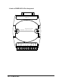
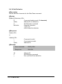
A Look at CYMOD 4531 & Pin Assignment
(RS- 232 )
Addressable RS-422/485
48 • CYMOD 4531
(B)GND
(R)+Vs
RXFGND
RX+
To RS-232 Converter
TX-
TX+
DEFAULT*
(G)DATA-
(Y) DATA+
CM 4531
Pin Definitions
Pin #
1
2
3
4
5
6
7
8
9
10
Signal Name
(Y)DATA+
(G)DATADEFAULT*
TX+
TXRX+
RXFGND
(R)+VS
(B)GND
RS-232
Description
RS-485 transmission line, positive
RS-485 transmission line, negative
Initial state setting
RS-422 transmission line, positive
RS-422 transmission line, negative
RS-422 receiving line, positive
RS-422 receiving line, negative
Field ground
Power supply, +10V~+30V
Ground
9-pin RS-232 connector
*The module is in DEFAULT mode when DEFAULT* pin connected to
GND while applying power on the module.
*Do not apply any power signal to DEFAULT* pin, just left it open or
connected it to GND.
CTS
RTS
6
7
8
9
1
2
3
4
5
TXD
RXD
GND
CYMOD 4531 • 49
Functional Block Diagram
+5V
Isolation +5V
Power Regulator
& Filter
Power Input
+10V ~ +30V
Isolation GND
GND
DC to DC
Converter
SW1
TXD
RXD
RTS
TVS
PTC
Data+
RS- 422/RS-485
RS-232
Receiver
/ Driver
Communication
Switching
Controller
DataReceiver/Drive
Rx+
RxTx+
GND
Opto-Isolation Communication
Direction Control
TVS : Transient Voltage Suppresser
PTC : Positive Temperature Coefficient
50 • CYMOD 4531
Tx-
5.2 Initialization & Installation
Software Installation
1. If CYMOD Administration is installed, skip the subsequent steps.
2. Backup your software diskette.
3. Insert the Administration disc into CD-ROM.
4. Change the drive path of CD-ROM to reflect your CD-ROMs assigned drive letter.
5. Find the setup of CYMOD Administration and run it.
6. Please follow the steps of setup program to succesfully install the Administration
software.
Objective of Initializing a Brand-New CYMOD 4531
All CYMOD modules except CYMOD 4520, 4510, and 4530, in a RS-485
network must have an unique address ID, however, every brand-new
CYMOD 4531 has a factory default setting as following:
♦
♦
♦
♦
Address ID is 0 1.
Baud rate is 9600 bps
RS-485 Interface
Host Watchdog timer is disable
Therefore, you must configure a new CYMOD unit before use,
otherwise the default address ID will conflict with other modules. The b aud
rate may also be changed according to user‘s requirements.
Default State
The CYMOD I/O modules must be set at Default State when you want to change
the default settings, such as the ID address, baud rate, check-sum status etc.
All CYMOD I/O modules have a special pin labeled as DEFAULT*. The module
will be in Default State if the DEFAULT* pin is shorted to ground when the power
is ON. In this state, the default configuration is set as following:
♦
♦
♦
Address ID is 00.
Baud rate is 9600 bps.
RS-485 Interface
CYMOD 4531 • 51
Therefore, the communication between host and the module can easily be
set with the same configuration, making the initialization of a module possible no
matter what configuration is set.
Initialization Equipments
♦
♦
♦
♦
♦
Host computer w ith an RS-232 port.
An installed RS-485 module (CYMOD 4520 or 4530) with 9600 baud
rate.
The brand new CYMOD 4531
Power supply (+10 to +30 VDC) for CYMOD modules
Administration utility software
Note1: Never Connect the DRFAULT* pin to Vs or power source.
Initialization Procedure
1. Power off the host computer and the installed CYMOD 4520 or 4530. Be sure
the baud rate of the CYMOD 4520 or 4530 is 9600 bps.
2. Connect a brand new CYMOD module with the RS-485. Set the module in
Default State by shorting the DEFAULT* pin. Refer to Figure 5.1 for detailed
wiring.
3. Power on the host computer.
4. Power on the power supply for CYMOD modules.
5. Use the CYMOD Administrating utility to configure the address ID, Baud rate
and check-sum status of the module.
52 • CYMOD 4531
Initialization Wiring
5.3. Install
Network
a
New
CYMOD
4531
to
a
Existing
Equipments for Install a New Module
♦
♦
♦
A existing CYMOD network
New CYMOD modules.
Power supply (+10 to +30 VDC).
Installation Procedure
1. Configure the new CYMOD module according to the initialization procedure in
section 2.2.
2. The baud rate and check-sum status of the new module must match with
the existing RS-485 network. The address ID must not conflict with other
CYMOD modules on the network.
3. Power off the CYMOD power supply of the existing RS-485 network.
4. Power off the host computer.
5. Wire the power lines for the new CYMOD with the existing network. Be careful
about the signal polarity.
6. Wire t he RS-485 data lines for the new CYMOD with the existing network. Be
careful about the signal polarity.
7. Wire to the input or output devices. Refer to section 2.4 for illustrations.
8. Power on the host computer.
9. Power on the CYMOD local power supply.
10. Use the administration utility to check entire network.
CYMOD 4531 • 53
Application Wiring
RX+
TX+
RX-
TX-
TX+
RX+
CTS
RTS
TX-
6
7
8
9
1
2
3
4
5
TXD
RXD
RTS
CTS
GND
6
7
8
9
1
2
3
4
5
RXD
TXD
GND
RX-
Host with RS-422/485 I/F
RS-232 Device
DATA+
DATA+
DATA-
DATA-
CM 4524
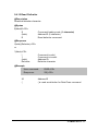
5.4 Command Set
5.4.1 Command and Response
Introduction
The CYMOD command is composed by numbers of characteristics, including
the leading code, address ID, the variables and a carriage return to indicate the
end of a command. The host computer can command only one CYMOD
module. The slave device may or may not give response to the command.
54 • CYMOD 4531
(Leading
Code)
(Addr)
(Command
Variable)
[Data]
[Checksum]
<>
Leading Code is the first character of the CYMOD
command. All CYMOD commands need a command
leading code, such as %,$,#,@,...etc.
1- character
Module’s address ID, the value is in the range of 00 - FF
(Hexadecimal) if no specified in the following.
2- character
Items indicate command codes or value of variables.
Variable length
Some output commands need data.
Variable length
Checksum in brackets indicates an optional parameter.
This field is required only if checksum is enabled.
2- character
Identifies a control code character, such as <CR> for
carriage return, its value is 0x0D. 1- character
Format of CYMOD Commands
(Leading Code)(Addr)(Command)[Data]<CR>
Example:
User
Command:
$012<CR>
Response:
!01400600<CR>
$:
01:
2:
<CR>:
LeadingCode
Address
Command (Read Configuration)
Carriage return 0x0D
CYMOD 4531 • 55
Response of CYMOD Commands
The response message depends on CYMOD command. The response is also
composed with several characteristics, including leading code, variables, and
carriage return for ending. There are two kinds of leading code for response
message: ”!“ or ”>“ means valid command, and ”?“ means invalid. By checking
the response messages, a user can monitor device status.
Note : Under the following conditions, there will be no response
message.
1. The specified address ID does not exist.
2. Syntax error.
3. Communication error.
4. Some special commands do not have response.
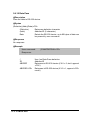
5.4.2 Summary of Command Set
Command
General Commands
Set Configuration
Command Set of Digital I/O Modules
Syntax
Read Configuration
Read Module Name
Read Firmware Version
Soft Reset
Reset Status
Functional Commands
Set RTS Status
Read RTS Status
Read CTS Status
Set Device ID
Read Device ID
Set Delimiter
Read Delimiter
Data Pass
Open/Close Data Gate
56 • CYMOD 4531
%(OldAddr)(NewAddr)
(TypeCode)(BaudRate)
(CheckSumFlag)
$(Addr)2
$(Addr)M
$(Addr)F
$(Addr)RS
$(Addr)5
$(Addr)0(RTS Status)
$(Addr)3
$(Addr)1
$(Addr)6(Device ID)
$(Addr)7
$(Addr)C(Delimiter)
$(Addr)D
(Delimiter)(Addr)(Data)
&(Addr)8(Data Gate Mode)
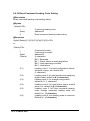
Special Commands
Read Command Leading Code
Setting
Change Command Leading
Code Setting
Set Host Watchdog / Safety Value
Read Host WatchDog / Safe
Value
Host is OK
~(Addr)0
~(Addr)10(C1)(C2)(C3)
(C4)(C5)(C6)
~(Addr)2(Flag)(TimeOut) (SafeValue)
~(Addr)3
~**
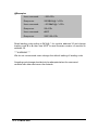
5.4.3 Set Configuration
@Description
Configure the basic setting about address ID, baud rate, and checksum.
@Syntax
%(OldAddr)(NewAddr)(TypeCode)(BaudRate)(DataFlag)<CR>
%
(OldAddr)
(NewAddr)
(TypeCode)
(BaudRate)
(DataFlag)
W. bit 3
W. bit 2
W. bit 1
0
1
0
1
0
Command leading code.
(1-character)
Original address ID. The default address ID of
a brand new module is 01. The value range of
address ID is 00 to FF in hexadecimal.
(2-character)
New addres s ID, if you don’t want to change
address ID, let new address ID equal the
old one. (2-character)
Type Code is fixed 40H. (2-character)
Communication baud rate, refer to Table 3-1 for
details. The first character is for RS-232, the
second character is for RS422/485.
(2-character)
Define check-sum status, refer to Table3-2 for
details. (4-character, WXYZ) WX is for module
system setting. YZ is for RS-232 configuration.
Normal addressable mode (*Default Setting)
Non-addressable mode (CM 4520 mode)
Disable checksum (*Default Setting)
Enable checksum
RS-422 interface
CYMOD 4531 • 57
1
W. bit 0
X. bit 3
X. bit 2
X. bit 1
X. bit 0
Y. bit 3
Y. bit 2
Y. bit 1
Y. bit 0
Z. bit 3
Z. bit 2
Z. bit 1 0
0
1
0
1
0
1
0
1
00
01
10
11
RS-485 interface (*Default Setting)
Don’t care, set to 0
Don’t care, set to 0
Don’t care, set to 0
Don’t care, set to 0
Don’t append <CR> in output string
Append <CR> in output string(*Default
Setting)
Don’t care, set to 0
Don’t care, set to 0
Don’t care, set to 0
Odd parity (*Default Setting)
Even parity
Non-parity mode (*DefaultSetting)
Parity mode
One stop bit (*Default Setting)
Two stop bit
5 data bit format
6 data bit format
7 data bit format
8 data bit format
@Response
!(Addr)<CR>
or
?(Addr)<CR>
(Addr)
!
Address ID.
Command is valid.
?
Command is invalid. Invalid parameter values,
When you wanted to change the setting without
grounding the DEFAULT* pin.
Note :When you want to change the checksum or baud rate or
DataFlag, the DEFAULT* pin should be grounded first.
58 • CYMOD 4531
@Example
User command:
%013040662103<CR>
Response:
!30<CR>
Item
%
01
30
Meaning
(Leading Code)
(OldAddr)
(NewAddr)
40
6
2103
(TypeCode)
(BaudRate
RS-422/485)
(BaudRate
RS-232)
(DataFlag)
<CR>
Carriage return
6
for
Description
Command leading code.
Original address ID is 01H.
New
address
ID
is
30H
(Hexadecimal).
6521 module.
Baud rate is 9600 for RS-422/485.
for
Baud rate is 9600 for RS-232.
Addressable mode
Checksum is dis able
RS-485 interface
Append <CR>
Non-parity
8 data bit
0x0D.
Code
Baudrate
3
1200 bps
4
2400 bps
5
4800 bps
6
9600 bps
7
19200 bps
8
38400 bps
9
115200 bps
A
57600 bps
Table 5-1. Baud rate setting code
CYMOD 4531 • 59
5.4.4 Read Configuration
@Description
Read the configuration of module on a specified address ID.
@Syntax
$(Addr)2<CR>
$
(Addr)
2
Command leading code
Address ID.
Command code for reading configuration
@Response
!(Addr)(TypeCode)(BaudRate)(DataFlag)<CR>
or
?(Addr)<CR>
!
?
(Addr)
(TypeCode)
(BaudRate)
(DataFlag)
Command is valid.
Command is invalid.
Address ID.
It always be 40 (Hex)
Current setting of communication baud rate of
RS-422/485 and RS-232, refer to Table 3-1 for
details.
Current setting of module setting and RS-232
configuration. Refer 3.3 for details.
@Example
User command:
$302<CR>
Response:
!3040662103<CR>
!
30
40
66
2103
60 • CYMOD 4531
Command is valid.
Address ID.
Digital I/O module.
Baud rate is 9600 for RS-422/485 and RS-232.
Addressable mode
Checksum is disable
RS-485 interface
Append <CR>
Non-parity
8 data bit
5.4.5 Read Module Name
@Description
Read module‘s name.
@Syntax
$(Addr)M<CR>
$
(Addr)
M
Command leading code.
Address ID
Read module name
@Response
!(Addr)(ModuleName) <CR>
or
?(Addr)<CR>
!
?
(Addr)
(ModuleName)
Com mand is valid.
Command is invalid.
Address ID.
CYMOD module's name.
@Example
User command:
$30M<CR>
Response:
!306521<CR>
!
30
6521
Command is valid.
Address
CM 4531 (RS-422/485 to RS-232 converter)
CYMOD 4531 • 61
5.4.6 Read Firmware Version
@Description
Read CYMOD module‘s firmware version.
@Syntax
$(Addr)F<CR>
$
(Addr)
F
Command leading code.
Address ID
Read module firmware version.
@Response
!(Addr)(FirmRev) <CR>
or
?(Addr)<CR>
!
?
(Addr)
(FirmRev)
Command is valid.
Command is invalid.
Address ID.
CYMOD module‘s firmware version.
@Example
User command:
$30F<CR>
Response:
!30E1.00<CR>
!
30
E1.00
62 • CYMOD 4531
Command is valid.
Address
Firmware Version
5.4.7 Soft Reset
@Description
Reset the module by software command
@Syntax
$(Addr)RS<CR>
$
(Addr)
RS
Command leading code.
Address ID
Soft Reset Command
@Response
!(Addr)<CR>
or
?(Addr)<CR>
!
?
(Addr)
Command is valid.
Command is invalid.
Address ID.
@Example
User command:
$30RS<CR>
Response:
!30<CR>
CYMOD 4531 • 63
5.4.8 Reset Status
@Description
Checks the reset status of module at specified address to see whether it has
been reset since the last reset status command was issued to the module.
@Syntax
$(Addr)5<CR>
$
(Addr)
5
Command leading code.
Address ID
Reset Status Command
@Response
!(Addr)(Status)<CR>
or
?(Addr)<CR>
!
?
(Addr)
(Status)
Command is valid.
Command is invalid.
Address ID.
0 : It has not been reset since the last reset
status command was issued.
1 : It has been reset since the last reset
status command was issued
@Example
User command:
$305<CR>
Response:
!300<CR>
Status is 0 means this module has not been reset since the last reset status
command was issued.
64 • CYMOD 4531
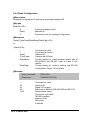
5.4.9 Set RTS Status
@Description
Set the RS-232 RTS signal to specified value.
@Syntax
$(Addr)0(RTS Status)<CR>
$
(Addr)
0
(RTS Status)
Command leading code. (1-character)
Address ID (2-character)
Set RTS Status command
0 : Set RTS Status to 0
1: Set RTS Status to 1
@Response
!(Addr)<CR>
or
?(Addr)<CR>
!
?
(Addr)
Command is valid
Command is invalid.
Address ID.
@Example
User command:
$3001<CR>
Response:
!30<CR>
30
0
1
Address ID
Set RTS Status command
Set the RTS signal to 1
CYMOD 4531 • 65
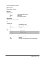
5.4.10 Read RTS Status
@Description
Read the RS-232 RTS status.
@Syntax
$(Addr)3<CR>
$
(Addr)
3
Command leading code. (1-character)
Address ID (2-character)
Read RTS status command
@Response
!(Addr)(RTS Status)<CR>
or
?(Addr)<CR>
!
?
(Addr)
(RTS Status)
Command is valid
Command is invalid.
Address ID.
0 : RTS Status is 0
1: RTS Status is 1
@Example
User command:
$303<CR>
Response:
!301<CR>
66 • CYMOD 4531
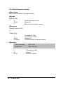
5.4.11 Read CTS Status
@Description
Read the RS-232 CTS status.
@Syntax
$(Addr)1<CR>
$
(Addr)
1
Command leading code. (1-character)
Address ID (2-character)
Read CTS status command
@Response
!(Addr)(CTS Status)<CR>
or
?(Addr)<CR>
!
?
(Addr)
(CTS Status)
Command is valid
Command is invalid.
Address ID.
0 : CTS Status is 0
1: CTS Status is 1
@Example
User command:
$301<CR>
Response:
!300<CR>
CYMOD 4531 • 67
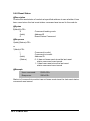
5.4.12 Set Device ID
@Description
Set the ID of RS-232 network.
@Syntax
$(Addr)6(Device ID)<CR>
$
(Addr)
6
Device ID
Command leading code. (1-character)
Address ID (2-character)
Set Device ID command
RS-232 Device ID for up to 24 bytes
@Response
!(Addr)<CR>
or
?(Addr)<CR>
!
?
(Addr)
Command is valid
Command is invalid.
Address ID.
@Example
User command:
$306CYMOD Network 1 <CR>
Response:
!30<CR>
30
6
CYMOD
Network 1
68 • CYMOD 4531
Address ID
Set Device ID command
Set the ID on address #30 to “CYMOD Network 1 ”
5.4.13 Read Device ID
@Description
Read the ID of RS-232 network.
@Syntax
$(Addr)7<CR>
$
(Addr)
7
Command leading code. (1-character)
Address ID (2-character)
Read Device ID command
@Response
!(Addr)(Device ID)<CR>
or
?(Addr)<CR>
!
?
(Addr)
Device ID
Command is valid
Command is invalid.
Address ID.
RS-232 Device ID
@Example
User command:
$307<CR>
Response:
!30CYMOD Network 1 <CR>
30
CYMOD
Network 1
Address ID
The ID on address #30 is “CYMOD Network 1 ”
CYMOD 4531 • 69
5.4.14 Set Delimiter
@Description
Set the delimiter character for the Data Pass command.
@Syntax
$(Addr)C(Delimiter)<CR>
$
(Addr)
C
Delimiter
Command leading code. (1-character)
Address ID (2-character)
Set Delimiter command
8 special character:
:[]^{}|~
can be used for delimiter
@Response
!(Addr)<CR>
or
?(Addr)<CR>
!
?
(Addr)
Command is valid
Command is invalid.
Address ID.
@Example
User command:
$30C{<CR>
Response:
!30<CR>
30
C
{
70 • CYMOD 4531
Address ID
Set Delimiter command
Use { as Data Pass delimiter
5.4.15 Read Delimiter
@Description
Read the delimiter character.
@Syntax
$(Addr)D<CR>
$
(Addr)
D
Command leading code. (1-character)
Address ID (2-character)
Read delimiter command
@Response
!(Addr)(Delimiter)<CR>
or
?(Addr)<CR>
!
?
(Addr)
Delimiter
Command is valid
Command is invalid.
Address ID.
Delimiter character
@Example
User command:
$30D<CR>
Response:
!30{<CR>
30
{
Address ID
{ is used as delimiter for Data Pass command
CYMOD 4531 • 71
5.4.16 Data Pass
@Description
Pass the data to RS-232 device.
@Syntax
(Delimiter)(Addr)(Data)<CR>
(Delimiter)
(Addr)
Data
Data pass delimiter character
Address ID (2-character)
Data to the RS-232 device, up to 80 bytes of data can
be passed by one command
@Response
No response
@Example
User command:
{30ABCDEFGHIJ<CR>
Response:
{
30
ABCDEF
ABCDEF<CR>
72 • CYMOD 4531
Use { as Data Pass delimiter
Address ID
Data pass to RS-232 device (if X.0 = 0, don’t append
<CR>)
Data pass to RS-232 device (if X.0 = 1, append <CR>
mode)
5.4.17 Open/Close Data Gate
@Description
Set the CM 4530 as non-addressable mode or addressable mode.
@Syntax
&(Addr)8(Data Gate Mode)<CR>
&
(Addr)
8
Data
Mode
Gate
Command leading code. (1-character)
Address ID (2-character)
Open/Close Data Gate Command
10: Open the CM 4530 as non-addressable mode
00: Close the CM 4530 as addressable mode
@Response
!(Addr)<CR>
or
?(Addr)<CR>
@Example
User command:
&30810<CR>
Response:
!30
&
30
10
Command leading code
Address ID
Open data gate
* Once the gate is open, the CM 4530 can be used as the CM 4520 for
transparent data converter.
CYMOD 4531 • 73
5.4.18 Read Command Leading Code Setting
@Description
Read command leading code setting status.
@Syntax
~(Addr)0<CR>
~
(Addr)
0
Command leading code.
Address ID
Read command leading code setting.
@Response
!(Addr)(Status)(C1)(C2)(C3)(C4)(C5)(C6)<CR>
or
?(Addr)<CR>
!
?
(Addr)
(Status)
(C1)
(C2)
(C3)
(C4)
(C5)
(C6)
74 • CYMOD 4531
Command is valid.
Command is invalid.
Address ID
(2-character)
Bit 0 : Reserved
Bit 1 : Power failure or watchdog failure
Bit 2 : Host watchdog is enable
Bit 3 : Host failure
Leading code 1, for read configuration status,
firmware version, etc. default is $.
(1-character)
Leading code 2, for read synchronize sampling,
digital output ,default is #. (1-character)
Leading code 3, for change configuration.
default is %. (1-character)
Leading code 4, for read alarm status, enable
alarm, etc. default is @. (1-character)
Leading code 5, for read command leading
code, change command leading code, etc.
default is ~. (1-character)
Leading code 6, this leading code is reserved.
Default is *. (1-character)
@Example
User command:
~300<CR>
Response:
!3000$#%@~*<CR>
Command leading code setting is $#%@~* for module address ID 30, current
status is factory default setting.
5.4.19 Change Command Leading Code Setting
@Description
User can use this command to change command leading code setting as
desired.
@Syntax
~(Addr)10(C1)(C2)(C3)(C4)(C5)(C6)<CR>
~
(Addr)
10
(C1)
(C2)
(C3)
(C4)
(C5)
(C6)
Command leading code.
Address ID, range (00 - FF).
Change command leading code setting.
Leading code 1, for read configuration status, firmware version,
etc. default is $. (1-character)
Leading code 2, for read synchronize sampling, digital
output ,default is #. (1-character)
Leading code 3, for change configuration.
default is %. (1-character)
Leading code 4, for read alarm status, enable alarm, etc. default
is @. (1-character)
Leading code 5, for read command leading code, change
leading code, etc. default is ~.
(1-character)
Leading code 6, this leading code is reserved. default is *.
(1-character)
@Response
!(Addr)< CR>
or
?(Addr)<CR>
!
?
(Addr)
Command is valid.
Command is invalid.
Address ID.
CYMOD 4531 • 75
@Examples
User command:
~300<CR>
Response:
!3000$#%@~*<CR>
User command:
~3010A#%@~*<CR>
Response:
!30<CR>
User command:
A30F
Response:
!30E1.00<CR>
Read leading code setting is $#%@~* for module address 30 and change
leading code $ to A, then use A30F to read firmware version of module on
address 30.
*** WARNING ***
We do not recommend users change the default setting of leading code.
A leading code change shouldd only be attempted when th e command
conflicts with other devices on the network.
76 • CYMOD 4531
5.4.20 Set Host Watchdog Timer
@Description
Set host watchdog timer, module will change to safety state when host is
failure.
@Syntax
~(Addr)2(Flag)(TimeOut)00<CR>
~
(Addr)
2
(Flag)
(TimeOut)
(SafeValue)
Command leading code.
Address ID, range (00 - FF).
Set host watchdog timer and safe state value.
0 : Disable host watchdog timer
1 : Enable host watchdog timer (1-character)
Host timeout value, between this time period host must
send (Host is OK) command to module, otherwise
module will change to safety state.
Range 01 - FF. (2-character)
One unit is 100 ms
01 = 1 * 100 = 100 ms
FF = 255 * 100 = 25.5 sec
8 channels safety value of digital output channels when
host is failure. (2-character)
@Response
!(Addr)<CR>
or
?(Addr)<CR>
!
?
(Addr)
@Example
Command is valid.
Command is invalid.
Address ID
User command:
~30211200<CR>
Response:
!30<CR>
30
2
1
12
Address ID
Set host watchdog timer and safe state value.
Enable host watchdog timer.
Timeout value. 0x12 = 18
18 * 100 = 1800 ms
00
CYMOD 4531 • 77
5.4.21 Read Host Watchdog Timer
@Description
Read host watchdog timer setting and the safety value.
@Syntax
~(Addr)3<CR>
~
(Addr)
3
Command leading code.
Address ID
Read host watchdog setting and module safety
state value.
@Response
!(Addr)(Flag)(TimeOut)00<CR>
or
?(Addr)<CR>
!
?
(Addr)
(Flag)
(TimeOut)
Command is valid.
Command is invalid.
Address ID, range (00 - FF).
0 : Host watchdog timer is disable
1 : Host watchdog timer is enable(1-character)
Host timeout value.
Range 01 - FF. (2-character)
One unit is 100 ms
01 = 1 * 100 = 100 ms
FF = 255 * 100 = 25.5 sec
00
@Example
User command:
~303<CR>
Response:
!3011200<CR>
06
1
12
00
78 • CYMOD 4531
Address ID
Host watchdog timer is enable.
Timeout value. 0x12 = 18
18 * 100 = 1800 ms
5.4.22 Host is OK
@Description
When host watchdog timer is enabled, host computer must send this command
to every module before timeout, otherwise “host watchdog timer enable”
module‘s output value will go to safety state output value.
@Syntax
~**<CR>
~
**
Command leading code.
Host is OK.
@Response
Note : Host is OK command has NO response.
@Example
User command:
~**<CR>
CYMOD 4531 • 79
6
Software Utility
6.1 Software Installation
1. Load the All-in-One CD into your CD-ROM drive.
2. Select and open CYMOD.
3. Select and open the CYMOD 4000 Admin Utility.
4.Select the driver you want to install and follow the setup instructions on
the screen.
6.2 How to Execute CYMOD Administration
Requirements:
1. At least one RS-232 communication port.
2. Microsoft Windows(version 3.1, 95/98/NT)
3. At least 2MB Hard Drive Space
4. A VGA monitor(optional)
5. Mouse (optional)
Execute the CYMOD Administration Utility
l
Run “CYMOD Administration Utility” Icon.
80 • Software Utility
6.3 CYMOD Administration Function Overview
Default RS-232 Communication Port Setting.
l
Communication Port : COM2
l
Baud Rate
: 9600
l
Data Bits
:8
l
Stop Bits
:1
l
Parity
: None
6.3.1 Change RS-232 Communication Port Setting.
Choose “Network-ComPort” to change setting.
Software Utility • 81
6.3.2 Search all exist CYMOD modules
Choose “Network-Search” to search all exist CYMOD modules in the current
RS-485 network.
You can change search addresses range from here.
82 • Software Utility
6.3.3 Using Operations
Operation-Terminal :
Operation-Configuration :
Operation-Monitor:
Operation-Diagnosti c:
Operation-Calibration:
Operation-Model Number:
Terminal Emulation allows users to
input commands and get a response message.
Select one exist CYMOD module and select
Configuration to adjust this module‘s
common and private setting.
Monitor all the module function on the
network.
Diagnostic module‘s function.
Some A/D modules need calibration
Select Model Number
Software Utility • 83
Term
ICON for Operation-Terminal
You can control all modules remotely using command mode, or by testing
your modules from this Terminal.
84 • Software Utility
Operation-Run Batch
:
Operation-Step Batch :
Operation-Display Batch:
Operation-Repeat
:
Diag
Run batch command file in BATCH.CMD
user can edit this text file.
Run the batch command step by step.
Display content of BATCH.CMD
Repeat one command n times
ICON for Operation-Diagnostic
This dialog is different by different-fuction modules.
Software Utility • 85
Cal
ICON for Operation-Calibration
This dialog is different by different fuction modules.
86 • Software Utility
6.3.4 Save and Print CYMOD Module Information
File-Save :
File-Print
File-Exit
:
:
Save all exist CYMOD module information as displayed in the
listbox in the current RS-485 network.
Print the CYMOD module information in the listbox.
Quit th e CYMOD Administration Utility.
Software Utility • 87
6.3.5 Version Information
Help-About
88 • Software Utility
Version information
Troubleshooting and
Maintenance
Preventive Maintain
l
Periodically check for loose connections.
ATTENTION: To avoid electircal shock or unintended operation of the
module, remove incoming power before checking connections.
Using the LED Indication
The LED provides status information on module operation.
LED
OFF
What it Means:
Module is not receiving input
power by loosing wiring.
ON(RED)
Flashing
Normal receiving state.
Normal transmitting state.
What to do:
Check module wiring,
cable connections, and
cable connections on
terminal block.
No action required.
No action required.
Other Malfunctions
Problem
What it Means:
What to do:
Do
not
function
Loose wiring
Incorrect DIP switch setting
Check wiring and cable
connection
Check baud rate and data
packet setting of the DIP
switch.
Troubleshooting and Maintenance • 89
Product Service
Diagnosis and Debug
CyberResearch, Inc. maintains technical support lines staffed by experienced
Applications Engineers and Technicians. There is no charge to call and we will
return your call promptly if it is received while our lines are busy. Most problems
encountered with data acquisition products can be solved over the phone. Signal
connections and programming are the two most common sources of difficulty.
CyberResearch support personnel can help you solve these problems, especially if
you are prepared for the call.
To ensure your call’s overall success and expediency:
1) Have the phone close to the PC so you can conveniently and quickly take action
that the Applications Engineer might suggest.
2) Be prepared to open your PC, remove boards, report back-switch or jumper
settings, and possibly change settings before reinstalling the modules.
3) Have a volt meter handy to take measurements of the signals you are trying to
measure as well as the signals on the board, module, or power supply.
4) Isolate problem areas that are not working as you expected.
5) Have the source code to the program you are having trouble with available so
that preceding and prerequisite modes can be referenced and discussed.
6) Have the manual at hand. Also have the product’s utility disks and any other
relevant disks nearby so programs and version numbers can be checked.
Preparation will facilitate the diagnosis procedure, save you time, and avoid repeated
calls. Here are a few preliminary actions you can take before you call which may
solve some of the more common problems:
1) Check the PC-bus power and any power supply signals.
2) Check the voltage level of the signal between SIGNAL HIGH and SIGNAL LOW,
or SIGNAL+ and SIGNAL– . It CANNOT exceed the full scale range of the board.
3) Check the other boards in your PC or modules on the network for address and
interrupt conflicts.
4) Refer to the example programs as a baseline for comparing code.
Warranty Notice
CyberResearch, Inc. warrants that this equipment as furnished will be free from
defects in material and workmanship for a period of one year from the confirmed
date of purchase by the original buyer and that upon written notice of any such
defect, CyberResearch, Inc. will, at its option, repair or replace the defective item
under the terms of this warranty, subject to the provisions and specific exclusions
listed herein.
This warranty shall not apply to equipment that has been previously repaired or
altered outside our plant in any way which may, in the judgment of the manufacturer,
affect its reliability. Nor will it apply if the equipment has been used in a manner
exceeding or inconsistent with its specifications or if the serial number has been
removed.
CyberResearch, Inc. does not assume any liability for consequential damages
as a result from our products uses, and in any event our liability shall not exceed
the original selling price of the equipment.
The equipment warranty shall constitute the sole and exclusive remedy of any Buyer
of Seller equipment and the sole and exclusive liability of the Seller, its successors
or assigns, in connection with equipment purchased and in lieu of all other warranties expressed implied or statutory, including, but not limited to, any implied
warranty of merchant ability or fitness and all other obligations or liabilities of seller,
its successors or assigns.
The equipment must be returned postage prepaid. Package it securely and insure it.
You will be charged for parts and labor if the warranty period has expired.
Returns and RMAs
If a CyberResearch product has been diagnosed as being non-functional, is visibly
damaged, or must be returned for any other reason, please call for an assigned
RMA number. The RMA number is a key piece of information that lets us track and
process returned merchandise with the fastest possible turnaround time.
PLEASE CALL FOR AN RMA NUMBER!
Packages returned without an RMA number will be refused!
In most cases, a returned package will be refused at the receiving dock if its
contents are not known. The RMA number allows us to reference the history of
returned products and determine if they are meeting your application’s requirements. When you call customer service for your RMA number, you will be asked to
provide information about the product you are returning, your address, and
a contact person at your organization.
Please make sure that the RMA number is
prominently displayed on the outside of the box.
• Thank You •
ii