1
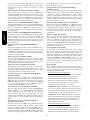
Free Cooling
The economizer will be allowed to help with cooling (Run Status
→MODE→OK.EC = Yes) if the supply air temperature sensor
reading is valid, there are no applied lockouts, and there is not a
dehumidification demand. There are four economizer lockouts that
can be applied at any time. Econo Cool OAT Lockout (Operating
Modes→ECON→E.LOC) occurs when the Outdoor Air
Temperature (OAT) is greater than the configured Econo Cool Hi
Temp Limit (Configuration→ECON→EH.LO) or less than the
configured Econo Cool Lo Temp Limit (Configuration→ECON
→EL.LO). Econo Diff DBulb Lockout (Operating Modes→
ECON→D.LOC) occurs when Diff Dry Bulb Control is enabled
(Configuration→ECON→DF.DB = Enable) and the accessory
return air temperature (RAT) is lower then the outdoor air
temperature (OAT). Econo Cool Enth Lockout (Operating
Modes→ECON →EN.LO) occurs when an enthalpy sensor is
installed and the Outdoor Enthalpy is HIGH. OAQ Lockout Mode
(Operating Modes→ECON→AQ.LO) occurs when the outdoor
air quality sensor is configured for lockout and the value is greater
then the OAQ Lockout Limit (Configuration→AIR.Q→OAQ.L).
Any one of these lockouts will disable economizer free cooling.
When the economizer is available for free cooling and the
compression is not on, the damper will open from minimum
position based on the supply air temperature (SAT) to provide free
cooling. In thermostat control mode, a Y1 command will utilize the
Low Cool SAT Setpoint (Setpoints → LCSP) to control the
economizer, and a Y2 will utilize the High Cool SAT Setpoint
(Setpoints → HCSP). In Space Sensor Control, the LCSP and
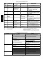
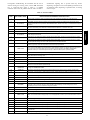
HCSP points are utilized according to Table 5.
If the control senses low suction pressure when the economizer is
also providing cooling, the maximum allowable economizer
position will be reduced. The Bottom Stage Max Econo
(Configuration→ECON→E.MXB) configuration sets the position
the damper will move to. Factory default configurations have been
qualified over a large range of conditions and should only be
changed with care.
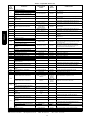
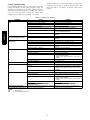
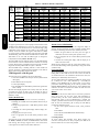
Table 5 – LCSP and HCSP Transitions for
Space Temperature Mode
CURRENT SAT
SET POINT
COOL DEMAND
(∆F)
NEXT SAT
SET POINT
LCSP
HCSP
LCSP
>0.5
<0
<–0.5
HCSP
LCSP
Exit Cooling
LEGEND
HCSP --- High Cool Set Point
LCSP --- Low Cool Set Point
SAT --- Supply ---Air Temperature
Direct Drive Units
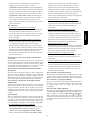
During free cooling the fan will run at Low Speed. After the
economizer reaches 100% (or Max) for 5 minutes, the fan will be
changed to High Speed. The fan will drop back to low speed if the
damper position falls below 75%. The compressor will be allowed
for use after the fan and economizer are 100% (or Max) for 5
minutes. Once compression is turned on the economizer and fan
will remain at 100% until the call for cooling is removed.
Belt Drive VFD Units
During free cooling the fan will start at Speed 1. After the
economizer reaches 100% (or Max) for 1 minute, the fan will be
changed to Speed 2. If the damper remains at 100% the speed will
increase every minute until maximum speed. If the damper starts to
close the current running fan speed will be locked in until cooling
call is removed. The compressor will be allowed for use after the
fan and economizer are 100% (or Max) for 5 minutes. Once
compression is turned on the economizer and fan will remain at
100% until the call for cooling is removed.
Unoccupied Free Cooling
The unoccupied free cooling algorithm attempts to maintain the
building space half way between the Occupied Cool Set Point
(Setpoints→OCSP)
and
Occupied
Heat
Set
Point
(Setpoints→OHSP) using only the economizer when the conditions
in the building and the outdoors are suitable, during unoccupied
periods. Three different configurations define this algorithm:
Unoccupied Free Cooling (Configuration→ECON→UEFC), Free
Cooling Preoccupancy Time (Configuration→ECON→FC.TM),
and Free Cool Low Temp Limit (Configuration→ECON→FC.LO).
UEFC = 0 (Disabled)
When UEFC = 0, unoccupied free cooling is disabled. Cooling
will only occur if the space exceeds the unoccupied setpoints.
UEFC = 1 (Unoccupied)
When UEFC is set to 1, unoccupied free cooling can occur
throughout the entire unoccupied period. The space temperature
must be higher than the mid--point between the occupied cooling
and heating setpoints.
UEFC = 2 (Preoccupancy)
When UEFC is set to 2, unoccupied free cooling can only occur
when the time until the next occupied period is less than the Free
Cool PreOcc Time (FC.TM) in minutes.
Free Cool PreOcc Time (FC.TM)
FC.TM is the configuration that determines how many minutes
before occupancy that free cooling can occur when set for
Preoccupancy (UEFC = 2).
Free Cool Low Temp Limit (FC.LO)
Unoccupied free cooling cannot occur if the Outdoor Air
Temperature (Temperature→AIR.T→OAT) is less than FC.LO.
Power Exhaust (Direct Drive ECM units)
To enable power exhaust, Configuration→ECON→PE.EN must
be set to ENBL. If power exhaust is enabled, Power Exhaust 1 will
turn on when the economizer position is greater than the value of
Configuration→ECON→PE.1 and the fan is running High
Speed. Power Exhaust 2 will turn on when the economizer position
21
48/50LC
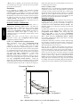
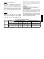
The shape of the Economizer Minimum Position vs. Fan Speed
curve is determined by the configuration parameters: Econ Min at
25% Fan speed (Configuration→ECON→MP.25), Econ Min at
50% Fan speed (Configuration→ECON→MP.50), Econ Min at
75% Fan speed (Configuration→ECON→MP.75) and Econ Min
at Max Fan speed (Configuration→ECON→MP.MX). These
configurations are preset at the factory for default purposes. The
Econ Min at Max Fan Speed (MP.MX) should be changed based
on the air balance of the unit for proper ventilation. The Econ Min
at 25% Fan speed (MP.25), Econ Min at 50% Fan speed (MP.50)
and Econ Min at 75% Fan speed (MP.75) damper positions will be
calculated and changed automatically after changing the Econ Min
at Max Fan Speed (MP.MX) and Supply Fan Maximum Speed
(Configuration→I.FAN→FS.MX).
The damper position curve can be field adjusted per application, if
needed. The Econ Min at 25% Fan speed (Configuration
→ECON→MP.25), Econ Min at 50% Fan speed (Configuration
→ECON→MP.50) and Econ Min at 75% Fan speed
(Configuration→ECON→MP.75) damper position are user
configurable and can be determined by setting the fan speed at 25,
50 and 75% and determining the damper position required to
maintain the Econ Min at Max Fan Speed (Configuration
→ECON→MP.MX) outside air CFM through the economizer
outside air dampers. The default calculations programmed into the
LC controls are based on a side shot economizer at 400 CFM/TON
Supply Air flow with negative 0.25 in H2O pressure in the return
duct. Econ Min at Max Fan Speed (FS.MN) is set by user based
on minimum required outside air ventilation CFM required for the
application. This procedure would be the same as if this were a CV
unit with the unit running at the design point CFM. This
determines the minimum position amount of outside air CFM
required when the fan is running at maximum speed.