1
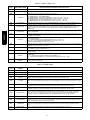
48/50LC 04---06
Single Package Rooftop Units
with ComfortLink Controls Version 1.X
and PURONr (R---410A) Refrigerant
Controls, Start---Up, Operation
and Troubleshooting
IMPORTANT: This literature covers 48/50LC 04--06 models with
ComfortLink Software version 1.x.
TABLE OF CONTENTS
Relative Humidity Sensor Control . . . . . . . . . . . . . . . . . . . . . . 9
CCN Communication . . . . . . . . . . . . . . . . . . . . . . . . . . . . . . . 9
Accessories . . . . . . . . . . . . . . . . . . . . . . . . . . . . . . . . . . . . . . . 9
Page
Programming Operating Schedules . . . . . . . . . . . . . . . . . . . . . 9
SAFETY CONSIDERATIONS . . . . . . . . . . . . . . . . . . . . . . . . . 2
SERVICE TEST . . . . . . . . . . . . . . . . . . . . . . . . . . . . . . . . . . . . 11
GENERAL . . . . . . . . . . . . . . . . . . . . . . . . . . . . . . . . . . . . . . . . . 3
Independent Outputs . . . . . . . . . . . . . . . . . . . . . . . . . . . . . . . 11
BASIC CONTROL USAGE . . . . . . . . . . . . . . . . . . . . . . . . . . . 3
Fan Test . . . . . . . . . . . . . . . . . . . . . . . . . . . . . . . . . . . . . . . . . 11
ComfortLink Control . . . . . . . . . . . . . . . . . . . . . . . . . . . . . . . . 3
Cooling Test . . . . . . . . . . . . . . . . . . . . . . . . . . . . . . . . . . . . . 11
Scrolling Marquee . . . . . . . . . . . . . . . . . . . . . . . . . . . . . . . . . . 3
Heating Test . . . . . . . . . . . . . . . . . . . . . . . . . . . . . . . . . . . . . . 11
Accessory Navigator Display . . . . . . . . . . . . . . . . . . . . . . . . . . 4
THIRD PARTY CONTROL . . . . . . . . . . . . . . . . . . . . . . . . . . 11
Operation . . . . . . . . . . . . . . . . . . . . . . . . . . . . . . . . . . . . . . . . . 4
Cooling/Heating Control . . . . . . . . . . . . . . . . . . . . . . . . . . . . 11
System Pilott and Touch Pilot Devices . . . . . . . . . . . . . . . . . 4
Dehumidification Control . . . . . . . . . . . . . . . . . . . . . . . . . . . 11
CCN Tables and Display . . . . . . . . . . . . . . . . . . . . . . . . . . . . . 4
Remote Occupancy . . . . . . . . . . . . . . . . . . . . . . . . . . . . . . . . 12
Conventions Used in This Manual . . . . . . . . . . . . . . . . . . . . . . 6
Fire Shutdown . . . . . . . . . . . . . . . . . . . . . . . . . . . . . . . . . . . . 12
START--UP . . . . . . . . . . . . . . . . . . . . . . . . . . . . . . . . . . . . . . . . . 6
Alarm Output . . . . . . . . . . . . . . . . . . . . . . . . . . . . . . . . . . . . . 12
Unit Preparation . . . . . . . . . . . . . . . . . . . . . . . . . . . . . . . . . . . . 6
Economizer Damper Control . . . . . . . . . . . . . . . . . . . . . . . . . 12
Compressor Mounting . . . . . . . . . . . . . . . . . . . . . . . . . . . . . . . 6
CONTROLS OPERATION . . . . . . . . . . . . . . . . . . . . . . . . . . . 12
Refrigerant Service Ports . . . . . . . . . . . . . . . . . . . . . . . . . . . . . 6
Display Configuration . . . . . . . . . . . . . . . . . . . . . . . . . . . . . . 12
Crankcase Heater . . . . . . . . . . . . . . . . . . . . . . . . . . . . . . . . . . . 6
Unit Configuration . . . . . . . . . . . . . . . . . . . . . . . . . . . . . . . . . 12
Compressor Rotation . . . . . . . . . . . . . . . . . . . . . . . . . . . . . . . . 6
Modes . . . . . . . . . . . . . . . . . . . . . . . . . . . . . . . . . . . . . . . . . . 13
Power Supply . . . . . . . . . . . . . . . . . . . . . . . . . . . . . . . . . . . . . 6
General Operation . . . . . . . . . . . . . . . . . . . . . . . . . . . . . . . . . 14
Internal Wiring . . . . . . . . . . . . . . . . . . . . . . . . . . . . . . . . . . . . . 6
Temperature Setpoint Determination . . . . . . . . . . . . . . . . . . . 14
Evaporator Fan . . . . . . . . . . . . . . . . . . . . . . . . . . . . . . . . . . . . 6
Occupancy Determination . . . . . . . . . . . . . . . . . . . . . . . . . . . 14
Condenser Fans and Motors . . . . . . . . . . . . . . . . . . . . . . . . . . . 7
Indoor Fan Operation . . . . . . . . . . . . . . . . . . . . . . . . . . . . . . . 15
Return--Air Filters . . . . . . . . . . . . . . . . . . . . . . . . . . . . . . . . . . 7
Cooling Operation . . . . . . . . . . . . . . . . . . . . . . . . . . . . . . . . . 16
Outdoor--Air Inlet Screens . . . . . . . . . . . . . . . . . . . . . . . . . . . . 7
Heating Operation . . . . . . . . . . . . . . . . . . . . . . . . . . . . . . . . . 18
Accessory Installation . . . . . . . . . . . . . . . . . . . . . . . . . . . . . . . 7
Economizer . . . . . . . . . . . . . . . . . . . . . . . . . . . . . . . . . . . . . . 20
Orifice Change (48LC) . . . . . . . . . . . . . . . . . . . . . . . . . . . . . . 7
Indoor Air Quality (IAQ) . . . . . . . . . . . . . . . . . . . . . . . . . . . . 22
Gas Heat (48LC) . . . . . . . . . . . . . . . . . . . . . . . . . . . . . . . . . . . 8
Temperature Compensated Start . . . . . . . . . . . . . . . . . . . . . . . 23
CONTROLS QUICK SET--UP . . . . . . . . . . . . . . . . . . . . . . . . . 8
Carrier Comfort Network (CCN)R Configuration . . . . . . . . . 24
Control Set Point and Confirmation Log . . . . . . . . . . . . . . . . . 8
Demand Limit . . . . . . . . . . . . . . . . . . . . . . . . . . . . . . . . . . . . 24
Thermostat Control . . . . . . . . . . . . . . . . . . . . . . . . . . . . . . . . . 8
Linkage . . . . . . . . . . . . . . . . . . . . . . . . . . . . . . . . . . . . . . . . . 25
Space Temperature Sensor Control -- Direct Wired
(T--55 or T--56 or T--59) . . . . . . . . . . . . . . . . . . . . . . . . . . . . . 8
Alarm Handling . . . . . . . . . . . . . . . . . . . . . . . . . . . . . . . . . . . 25
T--58 Communicating Room Sensor . . . . . . . . . . . . . . . . . . . . 8
CCN Linkage Control . . . . . . . . . . . . . . . . . . . . . . . . . . . . . . . 8
System Pilott -- Communication Space Sensor . . . . . . . . . . . 8
Thermidistat Control . . . . . . . . . . . . . . . . . . . . . . . . . . . . . . . . 8
Space Humidistat Control . . . . . . . . . . . . . . . . . . . . . . . . . . . . 9
TROUBLESHOOTING . . . . . . . . . . . . . . . . . . . . . . . . . . . . . . 26
Complete Unit Stoppage . . . . . . . . . . . . . . . . . . . . . . . . . . . . 26
Restart Procedure . . . . . . . . . . . . . . . . . . . . . . . . . . . . . . . . . . 26
Alarms and Alerts . . . . . . . . . . . . . . . . . . . . . . . . . . . . . . . . . 26
Control Module Communication . . . . . . . . . . . . . . . . . . . . . . 31
Communication Failures . . . . . . . . . . . . . . . . . . . . . . . . . . . . 31
Cooling Troubleshooting . . . . . . . . . . . . . . . . . . . . . . . . . . . . 32
SAFETY CONSIDERATIONS
Economizer Troubleshooting . . . . . . . . . . . . . . . . . . . . . . . . . 33
Installation and servicing of air-conditioning equipment can be
hazardous due to system pressure and electrical components. Only
trained and qualified service personnel should install, repair, or
service air-conditioning equipment. Untrained personnel can
perform the basic maintenance functions of replacing filters.
Trained service personnel should perform all other operations.
When working on air-conditioning equipment, observe precautions
in the literature, tags and labels attached to the unit, and other
safety precautions that may apply. Follow all safety codes. Wear
safety glasses and work gloves. Use quenching cloth for unbrazing
operations. Have fire extinguishers available for all brazing
operations.
Follow all safety codes. Wear safety glasses and work gloves. Have
fire extinguisher available. Read these instructions thoroughly and
follow all warnings or cautions attached to the unit. Consult local
building codes and National Electrical Code (NEC) for special
requirements.
Heating Troubleshooting . . . . . . . . . . . . . . . . . . . . . . . . . . . . 34
Phase Loss Protection . . . . . . . . . . . . . . . . . . . . . . . . . . . . . . 37
Thermistor Troubleshooting . . . . . . . . . . . . . . . . . . . . . . . . . 37
Transducer Troubleshooting . . . . . . . . . . . . . . . . . . . . . . . . . 38
Forcing Inputs and Outputs . . . . . . . . . . . . . . . . . . . . . . . . . . 38
MAJOR SYSTEM COMPONENTS . . . . . . . . . . . . . . . . . . . . 41
General . . . . . . . . . . . . . . . . . . . . . . . . . . . . . . . . . . . . . . . . . 41
Main Base Board (MBB) . . . . . . . . . . . . . . . . . . . . . . . . . . . . 47
Economizer Control Board (ECB) . . . . . . . . . . . . . . . . . . . . . 49
Integrated Gas Control (IGC) Board . . . . . . . . . . . . . . . . . . . 51
Low Voltage Terminal Board . . . . . . . . . . . . . . . . . . . . . . . . . 52
Communication Interface Board . . . . . . . . . . . . . . . . . . . . . . 52
48/50LC
Central Terminal Board (CTB) . . . . . . . . . . . . . . . . . . . . . . . . 52
Variable Frequency Drive (VFD) . . . . . . . . . . . . . . . . . . . . . . 54
VFD Diagnostics (with Keypad) . . . . . . . . . . . . . . . . . . . . . . 56
Scrolling Marquee Display . . . . . . . . . . . . . . . . . . . . . . . . . . 59
Accessory Navigatort Display . . . . . . . . . . . . . . . . . . . . . . . 59
Carrier Comfort Network (CCN)R Interface . . . . . . . . . . . . . 59
Protective Devices . . . . . . . . . . . . . . . . . . . . . . . . . . . . . . . . . 61
Field--Installed Accessories . . . . . . . . . . . . . . . . . . . . . . . . . . 61
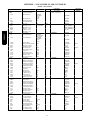
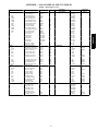
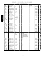
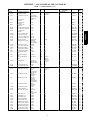
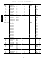
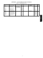
APPENDIX -- LOCAL DISPLAY AND
CCN TABLES . . . . . . . . . . . . . . . . . . . . . . . . . . . . . . . . . . . . . 64
CONTROL SET POINT AND CONFIGURATION LOG . . . . 78
.
Recognize safety information. This is the safety--alert symbol
When you see this symbol on the unit and in instructions or
manuals, be alert to the potential for personal injury.
Understand the signal words DANGER, WARNING, and
CAUTION. These words are used with the safety--alert symbol.
DANGER identifies the most serious hazards which will result in
severe personal injury or death. WARNING signifies a hazard
which could result in personal injury or death. CAUTION is used
to identify unsafe practices which may result in minor personal
injury or product and property damage. NOTE is used to highlight
suggestions which will result in enhanced installation, reliability, or
operation.
!
UNIT START--UP CHECKLIST . . . . . . . . . . . . . . . . . . . . . . . 83
WARNING
ELECTRICAL SHOCK HAZARD
Failure to follow this warning could cause personal injury
or death.
Before performing service or maintenance operations on
unit, turn off main power switch to unit and install lockout
tag. Ensure electrical service to rooftop unit agrees with
voltage and amperage listed on the unit rating plate.
!
CAUTION
UNIT DAMAGE HAZARD
Failure to follow this caution may cause equipment
damage.
This unit uses a microprocessor--based electronic control
system. Do not use jumpers or other tools to short out
components or to bypass or otherwise depart from
recommended procedures. Any short--to--ground of the
control board or accompanying wiring may destroy the
electronic modules or electrical components.
2
WARNING
FIRE, EXPLOSION HAZARD
Failure to follow this warning could result in personal
injury, death and/or property damage.
Improper installation, adjustment, alteration, service, or
maintenance can cause property damage, personal injury, or
loss of life. Refer to the User’s Information Manual
provided with this unit for more details.
Do not store or use gasoline or other flammable vapors and
liquids in the vicinity of this or any other appliance. What
to do if you smell gas:
1. DO NOT try to light any appliance.
2. DO NOT touch any electrical switch, or use any
phone in your building.
3.IMMEDIATELY call your gas supplier from a
neighbor’s phone. Follow the gas supplier’s
instructions.
4. If you cannot reach your gas supplier, call the fire
department.
The ComfortLink control system is easy to access through the use
of a unit-mounted display module. There is no need to bring a
separate computer to this unit for start-up. Access to control menus
is simplified by the ability to quickly select from 11 menus. A
scrolling readout provides detailed explanations of control
information. Only four, large, easy-to-use buttons are required to
maneuver through the entire controls menu. The display readout is
designed to be visible even in bright sunlight.
For added service flexibility, an accessory hand-held Navigator™
module is also available. This portable device has an extended
communication cable that can be plugged into the unit’s
communication network at the main control box. The Navigator
display provides the same menu structure, control access and
display data as is available at the unit-mounted Scrolling Marquee
display.
MODE
Run Status
Service Test
Temperature
48/50LC
!
Pressures
Setpoints
Alarm Status
Inputs
Outputs
Configuration
GENERAL
Time Clock
This publication contains Start--Up, Controls, Operation, Service,
and Troubleshooting information for the 48/50LC rooftop units.
(See Table 1.) These units are equipped with ComfortLink controls
version 1.X or higher and use Puronr refrigerant. The specific base
unit installation instructions, service manual and/or wiring label
diagram may also be required in conjunction with this book as a
guide to a specific unit on the roof. All the units in table 1 are
Staged Air Volume (SAVt) units that provide stand--alone or
network operation.
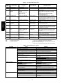
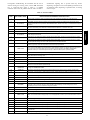
Table 1 – Rooftop Units
MODEL
48/50LC
SIZE
04
05
06
ESCAPE
ENTER
Operating Modes
NOMINAL TONS
3
4
5
BASIC CONTROL USAGE
ComfortLink Control
The ComfortLink control is a comprehensive unit-management
system. The control system is easy to access, configure, diagnose
and troubleshoot.
The ComfortLink control is fully communicating and cable-ready
for connection to the Carrier Comfort Network® (CCN) building
management system. The control provides high-speed
communications for remote monitoring via the Internet. Multiple
units can be linked together (and to other ComfortLink control
equipped units) using a 3-wire communication bus.
Alarms
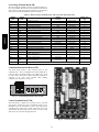
C06320
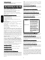
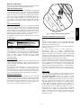
Fig. 1 -- Scrolling Marquee
Scrolling Marquee
This device is the keypad interface used to access the control
information, read sensor values, and test the unit. The Scrolling
Marquee is located in the main control box and is standard on all
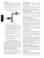
units. The Scrolling Marquee display is a 4-key, 4-character,
16-segment LED (light-emitting diode) display module. The
display also contains an Alarm Status LED. (See Fig. 1.)
The display is easy to operate using 4 buttons and a group of 11
LEDs that indicate the following menu structures:
S Run Status
S Service Test
S Temperatures
S Pressures
S Set points
S Inputs
S Outputs
S Configuration
S Timeclock
S Operating Modes
S Alarms
Through the Scrolling Marquee, the user can access all of the
inputs and outputs to check on their values and status, configure
operating parameters plus evaluate the current decision status for
operating modes. The control also includes an alarm history which
can be accessed from the display. In addition, through the Scrolling
Marquee, the user can access a built-in test routine that can be used
at start-up commissioning and to diagnose operational problems
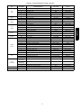
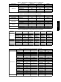
with the unit. (See Table 2.)
3
Accessory Navigator Display
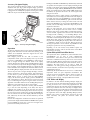
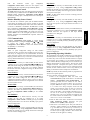
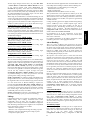
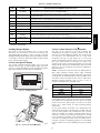
The accessory hand-held Navigator display can be used with the
48/50LLC units. (See Fig. 2.) The Navigator display operates the
same way as the Scrolling Marquee device. The Navigator display
is plugged into the LEN (local equipment network) port on either
CIB or the J3 port on the ECB (economizer control board).
Com
NA
T IM E
EWT
LW T
SETP
MO
fort
VIG
Link
ATO
R
12.
54. 58
44. 6°F
4 4 . 01 ° F
°F
DE
Run
Statu
s
Servi
ce Te
st
Temp
eratur
es
Pres
sures
Setpo
ints
Inputs
Al ar
m St
atu
s
Outpu
ts
Confi
gurat
ion
Time
Cloc
k
Opera
ting
Mode
Alarm
s
s
ER
48/50LC
ENT
ESC
C06321
Fig. 2 -- Accessory Navigator Display
Operation
All units are shipped from the factory with the Scrolling Marquee
display, which is located in the main control box. (See Fig. 1.) In
addition, the ComfortLink control also supports the use of the
handheld Navigator display.
Both displays provide the user with an interface to the
ComfortLink control system. The displays have up and down
arrow keys, an ESCAPE key and an ENTER key. These keys are
used to navigate through the different levels of the display
structure. The Navigator display and the Scrolling Marquee operate
in the same manner, except that the Navigator display has multiple
lines of display and the Scrolling Marquee has a single line. All
further discussions and examples in this document will be based on
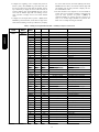
the Scrolling Marquee display. See Table 2 for the menu structure.
The four keys are used to navigate through the display structure,
which is organized in a tiered mode structure. If the buttons have
not been used for a period, the display will default to the AUTO
VIEW display category as shown under the RUN STATUS
category. To show the top-level display, press the ESCAPE key
until a blank display is shown. Then use the up and down arrow
keys to scroll through the top-level categories. These are listed in
Appendix A and will be indicated on the Scrolling Marquee by the
LED next to each mode listed on the face of the display.
When a specific mode or sub-mode is located, push the ENTER
key to enter the mode. Depending on the mode, there may be
additional tiers. Continue to use the up and down keys and the
ENTER keys until the desired display item is found. At any time,
the user can move back a mode level by pressing the ESCAPE key.
Once an item has been selected the display will flash showing the
item, followed by the item value and then followed by the item
units (if any).
Items in the Configuration and Service Test modes are password
protected. The display will flash PASS and WORD when required.
Use the ENTER and arrow keys to enter the four digits of the
password. The default password is 1111.
Pressing the ESCAPE and ENTER keys simultaneously will scroll
an expanded text description across the display indicating the full
meaning of each display point. Pressing the ESCAPE and ENTER
keys when the display is blank (MODE LED level) will return the
display to its default menu of rotating AUTO VIEW display items.
In addition, the password will need to be entered again before
changes can be made.
Changing item values or testing outputs is accomplished in the
same manner. Locate and display the desired item. If the display is
in rotating auto-view, press the ENTER key to stop the display at
the desired item. Press the ENTER key again so that the item value
flashes. Use the arrow keys to change the value of state of an item
and press the ENTER key to accept it. Press the ESCAPE key and
the item, value or units display will resume. Repeat the process as
required for other items.
There are some points that can be forced from the Scrolling
Marquee or the Navigator. If the user needs to force a variable,
follow the same process as when editing a configuration parameter.
A forced variable, regardless where the force has come from will
be displayed with a blinking “.” on a Scrolling Marquee and a
blinking “f” on a Navigator following its value. For example, if
economizer commanded position (EC.CP) is forced, the Navigator
display shows “80f”, where the “f” is blinking to signify a force on
the point. The Scrolling Marquee display shows “80.” Where the
“.” is blinking to signify a force on the point. Remove the force by
selecting the point that is forced with the key ENTER and then
pressing the up and down arrow keys simultaneously.
Depending on the unit model, factory-installed options and
field-installed accessories, some of the items in the various Mode
categories may not apply.
System Pilott and Touch Pilot Devices
The System Pilot device (33PILOT-01) and Touch Pilot device
(33CNTPILOT) can be used as CCN communication
user--interfaces. These devices can be put on the CCN bus and
addressed to communicate with any other device on the network.
Unlike the Scrolling Marquee and Navigator, these pilots read the
unit’s CCN tables and its CCN points can be monitored, forced, or
configured. The Pilot devices can be used to install and
commission a 3V zoning system, linkage compatible air source,
universal controller, and all other devices operating on the Carrier
communicating network.
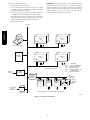
Additionally, the System Pilot device can serve as a wall-mounted
temperature sensor for space temperature measurement. The
occupant can use the System Pilot device to change set points. A
security feature is provided to limit access of features for
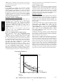
unauthorized users. See Fig. 3 for System Pilot device details.
CCN Tables and Display
In addition to the unit--mounted Scrolling Marquee display, the
user can also access the same information through the CCN tables
by using the Service tool or other CCN programs/devices. The
variable names used for the CCN tables and the Scrolling Marquee
menus may be different and more items may be displayed in the
CCN tables. Details on the CCN tables are included with the local
display menus in Appendix A. Appendix A is structured towards
the organization of the local display (Scrolling Marquee) menus.
Because of the variety of CCN programs and devices, the CCN
tables, sub--tables, and points are referenced within that
organization.
4
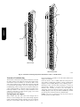
Table 2 – Scrolling Marquee Mode and Menu Display Structure
SERVICE
TEST
Service Test
Mode
(TEST)
↓
↓
Test Independent
Outputs
(INDP)
↓
Test Fans
(FANS)
Software
Version
Numbers
(VERS)
Control
Modes
(MODE)
↓
Cooling
Status
(COOL)
TEMPERATURES
PRESSURES
SETPOINTS
INPUTS
OUTPUTS
CONFIGURATION
Air
Temperatures
(AIR.T)
Thermostat
Inputs
(STAT)
Fan
Outputs
(FANS)
Display
Configuration
(DISP)
Refrigerant
Temperatures
(REF.T)
General
Inputs
(GEN.I)
Cool
Outputs
(COOL)
Unit
Configuration
(UNIT)
Air Quality
Inputs
(AIR.Q)
Heat
Outputs
(HEAT)
Indoor Fan
Configuration
(I.FAN)
Economizer
Outputs
(ECON)
Cooling
Configuration
(COOL)
↓
↓
↓
↓
↓
Test Cooling
(COOL)
↓
Test Heating
(HEAT)
↓
↓
↓
↓
Alarm
Relay
(ALRM)
↓
Heating
Status
(HEAT)
↓
Economizer
Status
(ECON)
TIME
CLOCK
Time of
Day
(TIME)
↓
↓
Month,
Date
Day and
Year
(DATE)
↓
↓
Daylight
Savings
Time
(DST)
↓
Local Time
Schedule
(SCH.L)
↓
Local
Holiday
Schedules
(HOL.L)
Economizer
Configuration
(ECON)
↓
↓
Air Quality
Cfg.
(AIR.Q)
↓
Alarm Relay
Config.
(ALM.O)
Component
Run Hours
(HRS)
↓
↓
Heating
Configuration
(HEAT)
↓
OPERATING
ALARMS
MODES
Control
Reset All
Modes
Current
(MODE)
Alarms
↓
(R.CURR)
Cool Mode
↓
Diagnostic
Reset
(COOL)
Alarm
↓
History
Heat Mode
(R.HIST)
Diagnostic
↓
Currently
(HEAT)
↓
Active
Economizer
Alarms
Diagnostic
(CURR)
(ECON)
↓
↓
Alarm
HIstory
Demand
(HIST)
Listing
(DMD.L)
↓
Component
Starts
(STRT)
↓
Sensor
Calibration
(TRIM)
↓
CCN
Configuration
Generic Status Display Table
MODIFY/
SELECT
NAVIGATE/
EXIT
SCROLL
+
PAGE
-
C06322
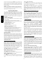
Fig. 3 -- System Pilott User Interface
Force Hierarchy
There is a hierarchy in CCN with regards to forcing a point.
Programs and devices write a force at different priority levels. A
higher level (smaller number, 1 being the highest) will override a
lower level force. The Scrolling Marquee uses a Control Force at
level 7. The Navigator writes a Service Force which is level 3.
System Pilots and Touch Pilots write Supervisor Forces at level 4.
Network programs can be set to write different level priority forces.
The GENERIC points table allows the service/installer the ability
to create a custom table in which up to 20 points from the 5 CCN
categories (Points, Config, Service--Config, Set Point, and
Maintenance) may be collected and displayed.
In the Service--Config table section, there is a table named
“GENERICS.” This table contains placeholders for up to 20 CCN
point names and allows the user to decide which points are
displayed in the GENERIC points sub--table under the status
display table. Each one of these placeholders allows the input of an
8--character ASCII string. Using a CCN interface, enter the Edit
mode for the Service--Config table “GENERICS” and enter the
CCN name for each point to be displayed in the custom points
table in the order they will be displayed. When done entering point
names, download the table to the rooftop unit control.
IMPORTANT: The computer system software (ComfortVIEWt,
Service Tool, etc.) that is used to interact with CCN controls,
always saves a template of items it considers as static (e.g., limits,
units, forcibility, 24--character text strings, and point names) after
the software uploads the tables from a control. Thereafter, the
software is only concerned with run time data like value and
hardware/force status. With this in mind, it is important that
anytime a change is made to the Service--Config table
“GENERICS” (which in turn changes the points contained in the
GENERIC point table), that a complete new upload be performed.
This requires that any previous table database be completely
removed first. Failure to do this will not allow the user to display
the new points that have been created and the CCN interface will
have a different table database than the unit control.
5
48/50LC
RUN
STATUS
Auto View
of
Run Status
(VIEW)
48/50LC
Conventions Used in This Manual
The following conventions for discussing configuration points for
the local display (Scrolling Marquee or Navigator™ accessory) will
be used in this manual.
Point names will be written with the Mode name first, then any
submodes, then the point name, each separated by an arrow symbol
(→). Names will also be shown in bold and italics. As an example,
the Thermostat Control Type which is located in the Configuration
mode, and Unit sub-mode would be written as Configuration→
UNIT→T.CTL.
This path name will show the user how to navigate through the
local display to reach the desired configuration. The user would
scroll through the modes and sub-modes using the up and down
keys. The arrow symbol in the path name represents pressing
ENTER to move into the next level of the menu structure.
When a value is included as part of the path name, it will be shown
at the end of the path name after an equals sign. If the value
represents a configuration setting, an explanation will be shown in
parenthesis
after
the
value.
As
an
example,
Configuration→UNIT→T.CTL = 1 (1 Stage Y1).
Pressing the ESCAPE and ENTER keys simultaneously will scroll
an expanded text description of the point name across the display.
The expanded description is shown in the local display tables but
will not be shown with the path names in text.
The CCN point names are also referenced in the local display
tables for users configuring the unit with CCN software instead of
the local display. See Appendix A of this manual.
START-UP
IMPORTANT: Do not attempt to start unit, even momentarily,
until all items on the Start--Up Checklist (see page 83) and the
following steps have been read/completed.
Unit Preparation
Check that unit has been installed in accordance with these
installation instructions and all applicable codes.
Compressor Mounting
Compressors are internally spring mounted. Do not loosen or
remove compressor holddown bolts.
Refrigerant Service Ports
The refrigerant system has a total of 3 Schrader-type service gauge
ports per circuit. One port is located on the suction line, one on the
compressor discharge line, and one on the liquid line. Be sure that
caps on the ports are tight.
Crankcase Heater
The compressor is equipped with a crankcase heater. There is a
temperature switch used to turn the crankcase heaters on and off
when the compressor is not running. If the ambient is above 75_F
the switch will prevent the crankcase heater from turning on, and if
the ambient is below 60_F the switch will allow the crankcase
heater on.
IMPORTANT: Unit power must be on for 24 hours prior to
start--up to allow the crankcase heater to run. Otherwise, damage to
the compressor may result.
Compressor Rotation
!
CAUTION
UNIT DAMAGE HAZARD
Failure to follow this caution may result in unit damage.
Improper wiring will cause compressor stoppage and alarm.
Correct wiring by switching leads as indicated below.
On 3-phase units, it is important to be certain the compressors are
rotating in the proper direction. To determine whether or not
compressors are rotating in the proper direction, use a
phase-rotation meter on the unit input power to check for
L1-L2-L3 or clockwise rotation or use the Service Test mode to
energize a compressor. If the compressor is rotating in the wrong
direction, the controls will stop the compressor and display alarm
for “Circuit A Failure to Pressurize,”.
NOTE: Indoor or outdoor fan rotation direction may not indicate
proper input power phase sequence, as some 3-phase units use
single-phase fan motors.
To correct the wrong compressor rotation direction, perform the
following procedure:
1. Turn off power to the unit and lock out the power.
2. Switch any two of the incoming unit power leads.
3. Turn on power to the unit.
4. Verify corrected compressor rotation.
Power Supply
All 208/230-v units are factory wired for 230-v power supply. If
the 208/230-v unit is to be connected to a 208-v power supply, the
transformers (TRAN1, TRAN2 and TRAN3) must be rewired by
moving the wire from the 230-volt connection and moving to the
200-volt terminal on the primary side of the transformer. Refer to
unit label diagram for additional information.
Internal Wiring
Check all electrical connections in unit control boxes; tighten as
required.
Evaporator Fan
The Evaporator fan should be checked and may need to be
adjusted for specific applications. The unit can have a direct drive
Electronic Commutated Motor (ECM) fan system or a belt drive
motor powered by a Variable Frequency Drive (VFD). Refer to the
unit product data for Fan Performance tables and physical data.
On direct drive units, the ECM has 5 speed taps to allow a range of
fan performance. The ComfortlLink control has 3 output wires to
connect to 3 different taps. From the factory the low and high
speed wires are connected to the first and second speed taps,
respectively. The ventilation speed tap is disconnected. The speed
taps increase the speed the higher the tap number, so the first tap is
the lowest speed and tap 5 is the highest speed. If the low and high
speed wires are moved to higher taps, the ventilation speed wire
can be wired into the motor. To activate the use of the ventilation
speed wire, the Number of Speeds (Configurations→I.FAN
→NSPD) configuration must be set to 3.
On belt drive units, the fan belt and variable pulleys are factory
installed and set, but may need to be adjusted for specific
applications. Check the fan to ensure its rotation is in the proper
direction before adjusting performance. To alter fan performance,
first adjust the pulley settings to provide the applications full load
design air flow when running at the Supply Fan Maximum Speed
(Configuration→UNIT→FS.MX). The unit operating speeds can
then be adjusted with Supply Fan Speed 1 (Configuration
→I.FAN→F.SP1), Supply Fan Speed 2 (Configuration→I.FAN
→F.SP2), Supply Fan Speed 3 (Configuration→I.FAN→F.SP3),
and Fan Speed – Ventilation (Configuration→I.FAN→FS.VN).
Set the indoor fan pulley to the application design point CFM for
heating and cooling at 100% fan speed so that the CFM is not
lower than the minimum CFM allowed in the product data. If the
exact CFM cannot be set by the half turn pulley settings then adjust
the Supply Fan Maximum Speed (FS.MX) to fine tune the CFM to
the application requirements. The VFD’s settings should not be
used for adjusting fan performance. Specific VFD information can
be found in the major components section.
IMPORTANT: The Supply Fan Maximum Speed (FS.MX) RPM
must not produce a supply CFM that is lower than the minimum
CFM allowed in the product data for heating and cooling.
6
Outdoor--Air Inlet Screens
For belt drive units with a power exhaust option, the controls
require an accurate supply duct CFM at the unit design point
where the indoor fan will run at the Supply Fan Maximum
Speed (FS.MX) for proper operation. The supply duct CFM is
configured by the Indoor Fan Max Speed CFM
(Configuration→ ECON→ IDF.C). Default values for Indoor
Fan Max Speed CFM (IDF.C) are at 400 CFM per ton
(1200CFM for the 04 size,1600 CFM for the 05 size, and 2000
CFM for the 06 size). It is preferred to use the supply duct CFM
from an air balance report to configure the Indoor Fan Max
Speed CFM (IDF.C). If an air balance report is not available,
then use the fan tables to determine Fan Max Speed CFM
(IDF.C). When using the fan tables to determine Fan Max Speed
CFM (IDF.C) set Economizer Position Test (Service
Test→ INDP→ ECON) to 0 (Economizer Damper Closed) and
Indoor Fan Speed Test (Service Test→ FANS→ F.SPD) equal to
Supply Fan Maximum Speed (FS.MX). Measure the supply to
return duct static pressure difference and indoor fan RPM. Make
correction to static pressure for all options installed in the unit
per the accessory pressure drop table. Determine Indoor Fan
Max Speed CFM (IDF.C) on the fan table where the corrected
static pressure and RPM cross.
Outdoor-air inlet screens must be in place before operating unit.
Accessory Installation
Check to make sure that all accessories including space thermostats
and sensors have been installed and wired as required by the
instructions and unit wiring diagrams.
This unit is factory assembled for heating operation using natural
gas at an elevation from sea level to 2000 ft.
Use accessory high altitude kit when installing this unit at an
elevation of 2000 to 7000 ft. For elevations above 7000 ft, refer to
High Altitude section to identify the correct orifice size for the
elevation. Purchase these orifices from your local Carrier dealer.
Follow instructions in accessory Installation Instructions to install
the correct orifices.
Use accessory LP (liquid propane) gas conversion kit when
converting this unit for use with LP fuel usage for elevations up to
7000 ft. For elevations above 7000 ft, refer to High Altitude
section to identify the correct orifice size for the elevation.
Purchase these orifices from your local Carrier dealer. Follow
instructions in accessory Installation Instructions to install the
correct orifices.
Condenser Fans and Motors
Condenser fans and motors are factory set.
Return--Air Filters
Check that correct filters are installed in filter tracks (see Physical
Data table in Installation Instructions). Do not operate unit without
return-air filters.
INDOOR
BLOWER
ACCESS
PANEL
CONTROL BOX
ACCESS PANEL
FILTER
ACCESS PANEL
INDOOR COIL
ACCESS PANEL
GAS SECTION
ACCESS PANEL
UNIT FRONT
UNIT BACK
C12218
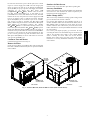
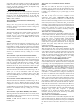
Fig. 4 -- 48/50LC SRT Units, Panel and Filter Locations (48LC*06 Unit Shown)
7
48/50LC
Orifice Change (48LC)
Gas Heat (48LC)
Thermostat Control
Inspect the gas heat section of the unit. Verify the number of
burners match the number of heat exchanger openings and the
burner assembly is properly aligned. If the orifices were changed
out for elevation or Liquid Propane purposes, verify proper
installation. Visually inspect other components in heat section.
Verify gas pressures before turning on heat as follows:
1. Turn off field-supplied manual gas stop, located external to
unit.
2. Connect pressure gauge to supply gas tap, located on
field-supplied manual shutoff valve. (See Fig. 5.)
Wire accessory thermostat to the corresponding R, Y1, Y2, W1,
W2, and G terminals on the field connection terminal board located
at the unit control box.
The Unit Control Type configuration, Configuration
→UNIT→U.CTL, default value is for Thermostat (2) so there is
no need to configure this item.
The Thermostat Control Type, Configuration →UNIT→T.CTL,
selects the unit response to the thermostat inputs above.
NOTE: May not be compatible with heat anticipator thermostats.
MANUAL SHUT OFF
(FIELD SUPPLIED)
GAS
SUPPLY
48/50LC
PRESSURE TAP
(1/8˝ NPT PLUG)
TO
Space Temperature Sensor Control -- Direct Wired
(T--55 or T--56 or T--59)
Wire accessory space temperature sensor(s) to the T-55 terminals
on the field connection terminal board located at the unit control
box. Refer to Field-Installed Accessories section for additional
information.
The Unit Control Type configuration, Configuration
→UNIT→U.CTL, must be set to Space Sensor (3). The jumper
wire in the installer’s packet must be connected between R and W1
on TB for heating mode to operate.
T--58 Communicating Room Sensor
UNIT
UNION
SEDIMENT TRAP
C09242
Fig. 5 -- Field Gas Piping
3. Connect pressure gauge to manifold pressure tap.
4. Turn on field-supplied manual gas stop. Enter Service Test
mode by setting Service Test→TEST to “ON” using the
Scrolling Marquee display. Temporarily install the jumper
wire between “R” and “W1” on TB. Use the Service Test
feature to set Service Test→HEAT→HT.1 to ON (first stage
of heat) using the Scrolling Marquee.
5. After the unit has run for several minutes, verify the supply
gas pressure is adequate per the base unit installation instructions. If not, adjust accordingly.
NOTE: Supply gas pressure must not exceed 13.0--in. wg.
6. Set Service Test→HEAT→HT.1 to OFF using Scrolling
Marquee.
7. Remove jumper wire if the unit will be operating under
thermostat mode. The jumper must remain if a space
temperature sensor (T-55, T-56, T-58, or System Pilot™
device) will control the unit.
8. Exit Service Test mode by setting Service Test→TEST to
“OFF” using the Scrolling Marquee.
CONTROLS QUICK SET--UP
The following information will provide a quick guide to setting up
and configuring the 48/50LC series units with ComfortLink
controls. Unit controls are pre-configured at the factory for
factory-installed options. Field-installed accessories will require
configuration at start-up. Service Test is recommended for initial
start--up. Additionally, specific job requirements may require
changes to default configuration values. See the CCN and Display
parameter tables and other sections of these instructions for more
details. Refer to the Major System Components or accessory
installation instructions for specific wiring detail.
Control Set Point and Configuration Log
During start up, accessory installation, and equipment service set
points and/or configuration changes might have to be made. When
setting set points or changing configuration settings,
documentation is recommend. The Control Log starting on page
78. should be filled out and left with the unit at all times, a copy
should also be provided to the equipment owner.
Install the T-58 communicating thermostat. Connect the CCN
communication bus from the T-58 to the CCN terminals on the
field connection terminal board located at the unit control box.
Configure the unit’s CCN communication element number, bus
number, and baud rate. Configure the T--58’s CCN communication
bus number and baud rate the same as the unit, while the element
number has to be different. Configure the T--58 to send SPT to the
unit’s element number. Refer to the Field--Installed Accessories
section for additional information.
The Unit Control Type configuration, Configuration
→UNIT→U.CTL, must be set to Space Sensor (3). The jumper
wire in the installer’s packet must be connected between R and W1
on TB for heating mode to operate.
CCN Linkage Control
The CCN communication must be properly configured for the
48/50LC units and all other devices. Linkage configuration is
automatically done by the supervisory CCN Linkage device.
The Unit Control Type configuration, Configuration
→UNIT→U.CTL must be set to Space Sensor (3). The jumper
wire in the installer’s packet must be connected between R and W1
on TB for heating mode to operate.
Installation of an accessory supply air temperature (SAT) sensor in
the supply duct is recommended for Linkage applications. A
supply duct SAT measurement is valid for heating mode display,
while the factory-standard internal SAT is not valid for heating due
to its location upstream of the heating section. When installing the
supply duct SAT, the heating mode display is enabled by setting
Configuration→HEAT→SAT.H to ENBL.
Installation of an accessory return air temperature (RAT) sensor in
the return duct and wired to the space sensor input is recommended
for Linkage applications. This will allow the unit to continue to
run if Linkage communication is lost.
System Pilott -- Communication Space Sensor
Install the System Pilot and connect the CCN communication bus
from it to the unit’s CCN connection on the low voltage terminal
board. Configure the unit’s CCN communication element number,
bus number, and baud rate. Refer to the System Pilot’s installation
instructions for configuring it to be used as a space temperature and
attaching it to a unit.
Thermidistat Control
The thermidistat is a thermostat and humidistat combined
and the inputs are provided on the field connection terminal board. The
unit control type configuration, Configuration→UNIT→U.CTL,
default value is for thermostat (2) so there is no need to configure this
8
Space Humidistat Control
The HUM terminal can be used on the Field Connection board when
the isolation relay is installed between the MBB and TB. The Space
Humidity Switch configuration, Configuration→UNIT→RH.SW,
identifies the normally open or normally closed status of this input at
LOW humidity.
Relative Humidity Sensor Control
For units with the economizer option (with the ECB--economizer
control board), the humidity sensor input is provided on the field
connection terminal board (TB). The sensor can be used in addition to
or instead of a humidistat or thermidistat. The RH Sensor on OAQ
Input configuration, Configuration→UNIT→RH.S=YES, identifies
that the sensor is being used instead of an OAQ sensor. Adjust RH
setpoints as needed. Terminal LPWR is the 24vdc loop power and
Terminal SPRH is the 4--20 mA signal input. Refer to the Field
Installed Accessories and Dehumidification Operation sections for
more information.
CCN Communication
Configure Configuration→CCN→CCN.A to desired element
number. (Default is 1.) Configure Configuration→CCN→ CCN.B
to desired bus number. (Default is 0.) Configure
Configuration→CCN→BAUD to desired code number for baud
rate (Default is 3 = 9600 baud).
Accessories
Below are quick configuration settings for field installed
accessories. If these accessories were installed by the factory, they
will already be configured. See the Field--Installed Accessories
section, third party control, control connection tables, and CCN or
Display parameter tables for any accessories not mentioned below
and any additional information on accessories.
Economizer
If an Economizer accessory was field installed, the unit must be
configured for it by setting Configuration→ECON→EC.EN to
YES. The default settings for the other economizer configurations
should be satisfactory. If they need to be changed, additional
information about these configuration settings can be found in the
Economizer section.
Power Exhaust
If a Power Exhaust accessory was field installed, the unit must be
configured for it by setting Configuration→ECON→PE.EN to
ENBL. The default settings for the other power exhaust
configurations should be satisfactory. If they need to be changed,
additional information about these configurations can be found in
the Power Exhaust section.
Electric Heat
If an Electric Heat accessory was field installed, the unit must be
configured for it by setting Configuration→HEAT→HT.TY to a
value of 2. The number of electric heat stages must be configured
by setting Configuration→HEAT→N.HTR per the installed
heater.
Fire Shutdown
If a Fire Shutdown or Smoke Detector accessory was field
installed, the unit must be configured for it by setting
Configuration→UNIT→FS.SW to normally open (1) or normally
closed (2) when there is not a fire alarm. Normally open (1) is the
preferred configuration.
Outdoor Enthalpy
If an Outdoor Enthalpy accessory was field installed, the unit must
be configured for it by setting Configuration→ECON→EN.SW,
identifies the normally open or normally closed status of this input
when the outdoor enthalpy is low.
IAQ Switch
If an IAQ Switch accessory was field installed, the unit must be
configured for it by setting Configuration→AIR.Q→II.CF,
identifies the normally open or normally closed status of this input
when the indoor air quality value is low (good) and also selects the
unit response to this input.
NOTE: An IAQ switch cannot be used if an enthalpy switch is
already on this input.
IAQ Sensor
If a CO2 Sensor accessory was field installed, the unit must be
configured for it by setting Configuration→AIR.Q→IA.CF
selects the unit response to this input. Default conversion to 0 to
2000 ppm.
OAQ Sensor
If an Outdoor Air Quality Sensor accessory was field installed, the
unit must be configured for it by setting Configuration→AIR.Q
→OA.CF selects the unit response to this input. Default
conversion to 0 to 2000 ppm.
Fan Status
If a Fan Status accessory was field installed, the unit must be
configured for it by setting Configuration→UNIT→FN.SW to
normally open (1) or normally closed (2). Normally open (1) is the
preferred configuration.
Filter Status
If a Filter Status accessory was field installed, the unit must be
configured for it by setting Configuration→UNIT→FL.SW to
normally open (1) or normally closed (2). Normally open (1) is the
preferred configuration.
Programming Operating Schedules
The ComfortLink controls will accommodate up to eight different
schedules (Periods 1 through 8), and each schedule is assigned to
the desired days of the week. Each schedule includes an occupied
on and off time. As an example, to set an occupied schedule for 8
AM to 5 PM for Monday through Friday, the user would set days
Monday through Friday to ON for Period 1. Then the user would
configure the Period 1 Occupied From point to 08:00 and the
Period 1 Occupied To point to 17:00. To create a different weekend
schedule, the user would use Period 2 and set days Saturday and
Sunday to ON with the desired Occupied On and Off times.
NOTE: By default, the time schedule periods are programmed for
24 hours of occupied operation.
To create a schedule, perform the following procedure:
1. Scroll to the Configuration mode, and select CCN
CONFIGURATION (CCN). Scroll down to the Schedule
Number (Configuration→CCN→SCH.O=SCH.N). If
password protection has been enabled, the user will be
prompted to enter the password before any new data is
accepted. SCH.N has a range of 0 to 99. The default value
is 1. A value of 0 is always occupied, and the unit will
control to its occupied set points. A value of 1 means the
unit will follow a local schedule, and a value of 65 to 99
means it will follow a CCN schedule. Schedules 2--64 are
not used as the control only supports one internal/local
schedule. If one of the 2--64 schedules is configured, then
the control will force the number back to 1. Make sure the
value is set to 1 to use a local schedule.
2. Enter the Time Clock mode. Scroll down to the LOCAL
TIME SCHEDULE (SCH.L) sub--mode, and press
ENTER. Period 1 (PER.1) will be displayed.
3. Scroll down to the MON.1 point. This point indicates if
schedule 1 applies to Monday. Use the ENTER command
to go into Edit mode, and use the Up or Down key to
change the display to YES or NO. Scroll down through the
rest of the days and apply schedule 1 where desired. The
schedule can also be applied to a holiday.
9
48/50LC
item.
The
thermostat
control
type
configuration,
Configuration→UNIT→T.CTL, selects the unit response to the
thermostat inputs above. See below for Space Humidity Switch.
4. Configure the beginning of the occupied time period for
Period 1 (OCC). Press ENTER to go into Edit mode, and
the first two digits of the 00.00 will start flashing. Use the
Up or Down key to display the correct value for hours, in
24--hour (military) time. Press ENTER and hour value is
saved and the minutes digits will start flashing. Use the
same procedure to display and save the desired minutes
value.
5. Configure the unoccupied time for period 1 (UNC). Press
ENTER to go into Edit mode, and the first two digits of the
00.00 will start flashing. Use the Up or Down key to display
the correct value for hours, in 24--hour (military) time. Press
ENTER and hour value is saved and the minutes digits will
start flashing. Use the same procedure to display and save
the desired minutes value.
6. The first schedule is now complete. If a second schedule is
needed, such as for weekends or holidays, scroll down and
repeat the entire procedure for period 2 (PER.2). If
additional schedules are needed, repeat the process for as
many as are needed. Eight schedules are provided. See
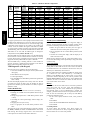
Table 3 for an example of setting the schedule.
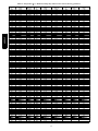
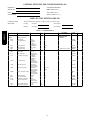
Table 3 – Setting an Occupied Time Schedule — Weekdays Only for 7:30 to 22:30
48/50LC
DISPLAY
MENU
TIMECLOCK
SCH.L
SUB-SUB
MODE
KEYPAD
ENTRY
ITEM
DISPLAY
ENTER
PER.1
ENTER
ITEM EXPANSION
COMMENT
Local Occupancy Schedule
OCC.1
Period Occupied Time
ENTER
00.00
Scrolling stops
ENTER
00.00
Hours Flash
Y
07.00
Select 7
ENTER
07.00
Change accepted, minutes flash
Y
07.30
Select 30
ENTER
07.30
Change accepted
ESCAPE
OCC.1
07.30
Period Occupied Time
B
UNC.1
00.00
Period Unoccupied Time
Item/Value/Units scrolls again
ENTER
00.00
Scrolling stops
ENTER
00.00
Hours Flash
Y
22.00
Select 22
ENTER
22.00
Change accepted, minutes flash
Y
22.30
Select 30
ENTER
22.30
Change accepted
ESCAPE
UNC.1
22.30
Period Unoccupied Time
B
MON.1
NO
Monday In Period
Item/Value/Units scrolls again
ENTER
NO
Scrolling stops
Y
YES
Select YES
ENTER
YES
Change accepted
ESCAPE
MON.1
YES
Monday In Period
B
TUE.1
NO
Tuesday In Period
Item/Value/Units scrolls again
ENTER
NO
Scrolling stops
Y
YES
Select YES
ENTER
YES
Change accepted
ESCAPE
TUE.1
YES
Tuesday In Period
B
WED.1
NO
Wednesday In Period
Item/Value/Units scrolls again
ENTER
NO
Scrolling stops
Y
YES
Select YES
ENTER
YES
Change accepted
ESCAPE
WED.1
YES
Wednesday In Period
B
THU.1
NO
Thursday In Period
Item/Value/Units scrolls again
ENTER
NO
Scrolling stops
Y
YES
Select YES
ENTER
YES
Change accepted
ESCAPE
THU.1
YES
Thursday In Period
B
FRI.1
NO
Friday In Period
Item/Value/Units scrolls again
ENTER
NO
Scrolling stops
Y
YES
Select YES
ENTER
YES
ESCAPE
FRI.1
Change accepted
YES
Friday In Period
ESCAPE
ESCAPE
10
Item/Value/Units scrolls again
SERVICE TEST
Independent Outputs
The independent (INDP) submenu is used to change output status
for the economizer, power exhaust stages, and alarm relay. These
independent outputs can operate simultaneously with other Service
Test modes. All outputs return to normal operation when Service
Test is turned off. When the economizer is using the factory default
Digital Control Type (Configuration→ECON→E.CTL is 1 or 2)
then the Economizer Calibration feature may be used to
automatically check and reset the economizer actuator range of
motion. Refer to the economizer operation section of more details.
Fan Test
The fans (FANS) submenu is used to change output status for the
indoor fan. On Direct Drive ECM fan units the indoor fan relays
can be energized or de--energized using the IDF1, IDF2, and IDF3
test. For units with a VFD the indoor fan speed test (F.SPD) is
available. F.SPD runs the fan at the desired speed entered. IDF Fan
Mode (F.MOD) will run the fan at the programmed speed for each
mode.
Cooling Test
The cooling (COOL) submenu is used to change output status for
the compressor, loader, and the low ambient outdoor fan. The fans
(FANS) and heating (HEAT) service test outputs are reset to OFF
for the cooling service test. Indoor fans and outdoor fans are
controlled normally to maintain proper unit operation. If LEN
VFD fan is configured, then the indoor fan speed will default to the
Supply
Cooling
Fan
Speed
configuration
point
(Configuration→I.FAN→F.SP2) when one compressor is turned
on. The Reduced Cool Fan Speed (F.SPD) can be used to change
the fan speed during cool test. When the compressor and loader are
turned on the fan will run at Supply Fan Maximum Speed
(FS.MX). On Direct Drive ECM units the fan will run Low Speed
when the compressor is turned on and will run High Speed when
the loader is turned on. The Reduced Cool Fan Speed (F.SPD) is
not used with ECM units. All normal cooling alarms and alerts are
functional. The low ambient outdoor fan test (L.ODF) can be
turned on and off while running the compressor.
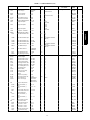
DISPLAY MENU/ .
SUB--- MENU/ . .
NAME
SERVICE TEST
TEST
INDP
ECON
E.CAL
PE.1
PE.2
ALRM
FANS
F.SPD
F.MOD
IDF.1
IDF.2
IDF.3
COOL
CMP.A
LDR_A
F.SPD
L.ODF
HEAT
HT.1
HT.2
F.SPD
EXPANDED NAME
Field Service Test Mode
Test Independent Outputs
Economizer Position Test
Calibrate Economizer
Power Exhaust 1 Test
Power Exhaust 2 Test
Alarm Relay Test
Test Fans
Indoor Fan Speed Test
IDF Fan Mode
Indoor Fan 1 Test
Indoor Fan 2 Test
Indoor Fan 3 Test
Test Cooling
Cool A Test
Cir A Loader Test
Reduced Cool Fan Speed
Low Amb ODF Test
Test Heating
Heat Stage 1 Test
Heat Stage 2 Test
Reduced Heat Fan Speed
VALUES
Off/On
0 to 100%
Off/On
Off/On
Off/On
Off/On
0 to 100%
0 to 7
Off/On
Off/On
Off/On
Off/On
Off/On
0 to 100%
0 to 100%
Off/On
Off/On
0 to 100%
Heating Test
The heating (HEAT) submenu is used to change output status for
the individual heat stages, gas or electric. The fans (FANS) and
cooling (COOL) service test outputs are reset to OFF for the
heating service test. Indoor and outdoor fans are controlled
normally to maintain proper unit operation. The fan will run at
Supply Fan Maximum speed (FS.MX) when running any heat
output. The Reduced Heat Fan Speed (F.SPD) is not used at this
time. All normal heating alarms and alerts are functional.
NOTE: Field terminal board terminal R must be connected to W1 for
the heat to operate in service test. Alert number T410 will occur as a
reminder if not done. If the normal unit control mode is thermostat
mode, then remove the R--W1 jumper after completing service test.
THIRD PARTY CONTROL
Third party controls may interface with the unit ComfortLink
controls through the connections described below. See other
sections of these instructions for more information on the related
unit control and configurations.
Cooling/Heating Control
The thermostat inputs are provided on the field connection terminal
board.
The
Unit
Control
Type
configuration,
Configuration→UNIT→U.CTL, must be 2 to recognize the
below inputs. Terminal R is the 24vac source for the following:
S Y1 = First stage cooling
S Y2 = Second stage cooling
S W1 = First stage heating
S W2 = Second stage heating
S G = Indoor fan
Dehumidification Control
The HUM terminal can be used on the Field Connection board
when the isolation relay is installed between the MBB and TB.
Humidity Switch configuration, Configuration→UNIT→RH.SW,
identifies the normally open or normally closed status of this input
at LOW humidity.
NOTE: Dehumidification is considered a cooling function in the
software.
11
48/50LC
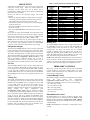
The Service Test function can be used to verify proper operation of
compressors, heating stages, indoor fan, power exhaust fans,
economizer, and the alarm relay. Use of Service Test is
recommended at initial system start up and during troubleshooting
(See Table 4 for point details).
Service Test mode has the following changes from normal
operation:
S Outdoor air temperature limits for cooling circuits, economizer,
and heating are ignored. Normal compressor time guards and
other staging delays are reduced to 30 seconds or less.
S Circuit alerts are limited to 1 strike (versus 3) before changing to
alarm shut down state.
S The status of ALM.N is ignored so all alerts and alarms are
broadcast on CCN.
S The words “SERVICE TEST” are inserted into every alarm
message.
Service test can only be turned ON/OFF at the unit display. Once
turned ON, other entries may be made with the display or through
CCN. To turn Service Test on, change the value of TEST to ON.
To turn service test off, change the value of TEST to OFF.
NOTE: Service Test mode may be password protected. Refer to
Basic Control Usage section for more information. Depending on
the unit model, factory--installed options, and field--installed
accessories, some of the Service Test functions may not apply.
Table 4 – Service Test Modes and Submodes Directory
CONTROLS OPERATION
Remote Occupancy
The remote occupancy input is provided on the field connection
terminal board (TB). The Remote Occupancy Switch
configuration, Configuration→UNIT→RM.SW, identifies the
normally open or normally closed status of this input when
unoccupied.
S RMOC = 24 VAC signal input
S R--2 = 24 VAC source for dry contact
Fire Shutdown
48/50LC
The fire shutdown input is provided for unit shutdown in response
to a fire alarm or smoke detector. The Fire Shutdown Switch
configuration, Configuration→UNIT→FS.SW, identifies the
normally open or normally closed status of this input when there is
no fire alarm.
S FDWN = 24 VAC signal input
Display Configuration
The Configuration→DISP submenu is used to configure the local
display settings.
Metric Display (METR)
This variable is used to change the display from English units to
Metric units.
Language Selection (LANG)
This variable is used to change the language of the ComfortLink
display. At this time, only English is available.
Password Enable (PROT)
This variable enables or disables the use of a password. The
password is used to restrict use of the control to change
configurations.
Alarm Output
Service Password (PSWD)
The alarm output is provided on the field connection terminal
board to indicate a current alarm status. The output will be 24VAC
if a current alarm exists.
S C--2 = 24 VAC common
S X = 24 VAC signal output
This variable is the 4-digit numeric password that is required if
enabled.
Test Display LEDs (TEST)
Economizer Damper Control
Many configurations that indicate what factory options and/or field
accessories are installed and other common operation variables are
included in Unit Configuration (Configuration→UNIT). These
configurations will be set in the factory for the factory--installed
options (FIOPs). Field--installed accessories installed will require
configuration changes. General unit configurations are also
covered under this Unit Configuration menu.
For units with the economizer option or accessory and the ECB
control board, the damper position can be directly controlled
through the IAQ sensor input provided on the field connection
terminal board. The IAQ Analog Input configuration,
Configuration→AIR.Q→IA.CF will have to set to 3 (Control
Minimum Position). When IA.CF = 3, an external 4 to 20 mA
source is used to move the damper 0% to 100% directly.
IAQ = 4--20mA + signal
COM = 4--20mA -- common
NOTE: In this mode, preset minimum positions configurations are
not valid, the damper position may exceed the input position to
provide economizer cooling and CO2 sensor input can not be used
for DCV control. Refer to the Indoor Air Quality operation section
for more information.
This is used to test the operation of the ComfortLink display.
Unit Configuration
Start-- Up Delay (S.DLY)
This configuration sets the control start-up delay after the power is
interrupted. This can be used to stagger the start-up of multiple
units.
Unit Control Type (U.CTL)
This configuration defines if temperature control is based on
thermostat inputs or space temperature sensor input.
S U.CTL = 2 (Thermostat) – The unit determines cooling and
heating demand by the state of G, Y1, Y2, W1, and W2 inputs
from a space thermostat. This value is the factory default.
S U.CTL = 3 (Space Sensor) – The unit determines cooling and
heating demand based on the space temperature and the
appropriate set point. Used also as Linkage configuration. The
jumper wire in the installer’s packet must be connected between
R and W1 on the low voltage terminal board for heating mode to
operate.
Thermostat Control Type (T.CTL)
This configuration applies only if Unit Control Type is Thermostat
(Configuration→Unit→U.CTL = 2). The value determines
alternative system staging. See the specific operation sections for
more information. The factory default value is T.CTL = 0
(Adaptive).
Fan Status Switch (FN.SW)
This configuration identifies if a fan status switch is installed, and
what status (normally open, normally closed) the input is when the
indoor fan is OFF.
Filter Status Switch (FL.SW)
This configuration identifies if a filter status switch is installed, and
what status (normally open, normally closed) the input is when the
filter is CLEAN.
Fire Shutdown Switch (FS.SW)
This configuration identifies if a fire shutdown switch is installed,
and what status (normally open, normally closed) the input is when
the fire or smoke alarm is OFF (no alarm).
12
Remote Occupancy Switch (RM.SW)
System Mode (SYS)
This configuration identifies if a remote occupancy switch is
installed, and what status (normally open, normally closed) the
input is when UNOCCUPIED.
SAT Settling Time (SAT.T)
In Run Status and Operating Modes, the current system mode is
displayed with expandable text. This is an overall state of the unit.
Three states are: Unit Operation Disabled, Unit Operation Enabled,
or Service Test Enabled.
This configuration sets the settling time of the supply air
temperature (SAT). This tells the control how long to wait after a
stage change before trusting the SAT reading. See Adaptive
Thermostat Control (U.CTL = 2, T.CTL = 0) and Space Sensor
Control (U.CTL = 3) within the Cooling operation section for
more information. The factory default value is 240 seconds.
In Run Status and Operating Modes, the current allowed HVAC
mode is displayed with expandable text. This is the mode the unit
decides to run in based on its inputs. There are four main HVAC
modes; cooling has six different expanded texts. These modes are
shown below.
HVAC Mode (HVAC)
This configuration identifies if a return air temperature (RAT)
sensor is installed. A YES value enables RAT display. A NO value
disables RAT display. The RAT sensor can allow economizer
differential dry bulb control.
RH Sensor On OAQ Input (RH.S)
This configuration identifies if a space relative humidity sensor is
installed on the outdoor air quality (OAQ) input. A YES value
enables SP.RH display. The unit determines dehumidification
demand based on this input and the appropriate set point. A NO
value disables SP.RH display and use.
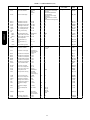
HVAC
Mode
Expanded Text
Brief Description
Disabled
HVAC Operation
Disabled
Unit is in test mode or System mode is disabled
Fan
Only
Ventilation
(fan--- only)
Fan may run for ventilation
Cooling
Cooling
Free Cooling
Unoccupied
Free Cooling
Mechanical cooling
Only economizer used for cooling
Only economizer use for cooling (occupied
cooling set point active)
Dehumidification
Dehum Cooling
Heating
Running advanced dehumidification
Running cooling with advanced dehumidification
Heating mode
Heating
Space Humidity Switch (RH.SW)
Indoor Fan Mode (F.MOD)
This configuration identifies if a space relative humidity switch is
installed on the humidistat (HUM) input, and what status (normally
open, normally closed) the input is when the space humidity is
LOW.
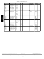
This displays the mode in which the fan is running. There are 8 fan
modes in total, the 1-Speed fans can only be in 1 of 2 modes (off or
High). Staged Air Volume (SAV) units can utilize all 8 modes if
programmed for it. The table below shows the 8 modes and a brief
description for each.
Temperature Compensated Start Cooling Factor
(TCS.C)
Fan
Mode
This factor is used in the equation of the Temperature
Compensated Start Time Bias for cooling. A setting of 0 minutes
indicates Temperature Compensated Start in Cooling is not
permitted.
Temperature Compensated Start Heating Factor
(TCS.H)
This factor is used in the equation of the Temperature
Compensated Start Time Bias for heating. A setting of 0 minutes
indicates Temperature Compensated Start in Heating is not
permitted.
Modes
The ComfortLink controls operate under a hierarchy of command
structure as defined by four main elements: the System Mode, the
HVAC Mode, the Occupied status, and the Unit Control Type.
The System Mode is the top level that defines three main states of
the control system: Disabled, Enabled, or Test.
The HVAC Mode is the next level that defines four main states of
functional operation: Disabled, Fan Only, Cool, and Heat.
The Occupied status affects set points for cooling and heating in
Space Sensor control mode and operation of the economizer for
indoor air quality ventilation and free cooling.
The Unit Control Type (Configuration→UNIT→U.CTL) defines
if temperature control is based on thermostat inputs or space
temperature sensor input.
The general operating mode of the control and the status of some
related operation lockouts are located on the display at two
locations: Run Status→ MODE and Operating Modes→ MODE.
Expanded Text
Brief Description
0
OFF
When the fan is off
1
Speed 1
Pre--- Low Speed
2
Speed 2
Low Speed
3
Speed 3
Pre--- High Speed
4
Max Speed
When running at Maximum Fan Speed
5
Vent
When in Ventilation mode and the fan is on
HVAC Operation Disabled (HV.DN)
Allow disabling of HVAC mode. This is only available on a
network connection and shows if the unit has been forced into the
disabled status.
Cool Setpoint In Effect (EFF.C)
This shows the actual setpoint that is being used for control during
cooling mode. If a 0 is displayed, then space sensor control is not
being used and the unit is being controlled by a thermostat.
Heat Setpoint In Effect (EFF.H)
This shows the actual setpoint that is being used for control during
heating mode. If a 0 is displayed, then space sensor control is not
being used and the unit is being controlled by a thermostat.
Currently Occupied (OCC)
Displays the current state of assumed space occupancy based on
unit configuration and inputs.
Timed Override in Effect (T.OVR)
Displays if the state of occupancy is currently occupied due to an
override.
Linkage Active (LINK)
Displays if a linkage communication “Linkage” is established
between the unit and a linkage source.
Demand Limit in Effect (D.LMT)
Displays if a demand limit has been placed on the unit’s capacity.
Compressor OAT Lockout (C.LOC)
Displays if operation of the compressor is prevented due to outdoor
temperature limit lockout.
13
48/50LC
RAT Sensor Installed (RAT.S)
Heat OAT Lockout (H.LOC)
Displays if heating operation is prevented due to outdoor
temperature limit lockout.
Econo Cool OAT Lockout (E.LOC)
Displays if economizer operation for cooling is prevented due to
outdoor temperature limit lockout.
48/50LC
General Operation
48/50LC units can provide cooling, dehumidification, heating, and
ventilation operation. Each unit will operate under one of two
basic types of control: thermostat or space temperature sensor.
There are many inputs, configurations, safety factors, and
conditions that ultimately control the unit. Refer to the specific
operation sections for detail on a specific unit operation.
When thermostat control is enabled (Configuration→UNIT
→U.CTL = 1), the unit will operate based on discrete input
commands (G, Y1, Y2, W1, and W2) and there is a one minute
time delay between modes and when re--entering a mode. The G
command calls for ventilation, the Y1 and Y2 commands call for
cooling, and the W1 and W2 commands call for heating.
Thermostat Control Type (Configuration→UNIT→T.CTL) affects
how cooling operates based on Y1 and Y2 commands and if
cooling/heating stage time guards are applied.
When space temperature sensor control is enabled (Configuration
→UNIT→U.CTL = 2), the unit will try to maintain the Space
Temperature (Temperatures→AIR.T→SPT) between the effective
cool and heat setpoints (Run Status→MODE→EFF.C and
EFF.H). However, to minimize unnecessary cool to heat and heat
to cool changes, there is a 10 minute delay after the last stage turns
off before the control will switch modes and a 1 minute delay when
re--entering the last mode. Linkage operation overrides the mode
changeover delay to 15 seconds. The cooling and heating Mode
Select Timeguard (Operating Modes→COOL→MS.TG and
Operating Modes→HEAT→MS.TG) show the remaining time
before allowing the respective mode to be entered.
Temperature Setpoint Determination
Setpoints are used to control the unit while under space
temperature sensor control. The Cool Setpoint in Effect (EFF.C)
and the Heat Setpoint in Effect (EFF.H) are the points in which the
unit is controlling to at a specific time. These points are read only
points and change according to occupancy, the offset slider status,
and network writes (Linkage or LON).
If the building is in occupied mode, the Occupied Cool Setpoint
(Setpoints→OCSP) and the Occupied Heat Setpoint (Setpoints
→OHSP) are active. When the building is in unoccupied mode,
the Unoccupied Cool Setpoint (Setpoints→UCSP) and the
Unoccupied Heat Setpoint (Setpoints→UHSP) are active. The
heating and cooling set points are also separated by a Heat--Cool
Set Point Gap (Setpoints→GAP) that is user configurable from 2
to 10 degrees F. This parameter will not allow the setpoints to be
set too close together, it will change the last setpoint adjusted if it is
set within the GAP.
When the space sensor has a setpoint slider adjustment, the cool
and heat setpoints (occupied) can be offset by sliding the bar from
one side to the other. The SPT Offset Range (+/--) (Setpoints
→STO.R) sets the total positive or negative degrees that can be
added to the setpoints. With the slider in the middle, no offset is
applied. Moving the slider to the “COOL” side will subtract from
each setpoint, and sliding it to the “WARM” side will add to the
setpoints. The slider offset being applied at any given time is
displayed as Space Temperature Offset (Temperatures→AIR.T
→SPTO).
Occupancy Determination
The building’s occupancy is affected by a number of different
factors. When the unit is operating with a space temperature sensor
(T--55, T--56, T--58 or T--59), occupancy affects the unit set points
and the operation of the economizer. If the unit is operating under
thermostat control, occupancy only affects the operation of the
economizer. If using a relative humidity sensor, then occupancy
will affect the RH setpoints. The factors affecting occupancy are
listed below from highest to lowest priority.
Level 1 Priority
Level 1 classification is a force/write to occupancy and can occur three
ways. Listed in order of priority: force on OCCUPIED, a write to
NVI_OCC, and a Linkage write. The CCN point OCCUPIED is
forced via an external device such as a ComfortIDt controller or a
service tool. When OCCUPIED is forced to YES, the unit is
considered occupied, when OCCUPIED is forced to NO, the unit is
considered unoccupied. If the 3rd party protocol LON is writing to
NVI_OCC, the control maps it to OCCUPIED as an input. If the unit
is being controlled by Linkage, the occupancy is communicated and
mapped to OCCUPIED as an input. LON and Linkage do not force
the point, only write to it, therefore a force applied to OCCUPIED
will override them.
If OCCUPIED is not being forced or written to, proceed to the
level 2 priority.
Level 2 Priority
Remote Occupancy Switch should be configured to either
Normally Open or Normally Closed when the user would like to
control the occupancy with an external switch. This switch is
field--supplied (24v, single pole, single throw [SPST]). There are
three possible configurations for the remote occupancy switch:
1. (Configuration→UNIT→RM.SW = 0) No Switch
2. (Configuration→UNIT→RM.SW = 1) Normally Open
Switch
3. (Configuration→UNIT→RM.SW = 2) Normally Closed
Switch
If the switch is configured to No Switch (0), the switch input value
will be ignored and software will proceed to level 3 priority. For
each type of switch, the appropriate configuration and states are
listed in the table below.
The Remote Occupancy Switch
(INPUTS→GEN.I→RM.OC) point will show the status of the
switch.
TYPE OF SWITCH
SWITCH
CONFIGURATION
Occupied when Closed
or Unoccupied when
Open
Normal Open (1)
Occupied when Open or
Unoccupied when
Closed
Normal Closed (2)
STATE OF SWITCH
AND STATE OF
OCCUPANCY
Open and Unoccupied
Closed and Occupied
Open and Occupied
Closed and Unoccupied
NOTE: To perform remote occupancy, an Economizer Control
Board must be installed in the unit.
14
The following occupancy options are determined by the state of
Occupancy Schedule Number (Configuration→CCN→SCH.O
→SCH.N) and the Global Schedule Broadcast (Configuration
→CCN→ BROD→B.GS).
1. (Configuration→CCN→SCH.O→SCH.N = 0)
The unit is always considered occupied and the
programmed schedule is ignored. This is the factory
default.
2. (Configuration→CCN→SCH.O→SCH.N = 1- 64)
Follow the local programmed schedule. Schedules 1 to 64
are local within the controller. The unit can only store one
local schedule and therefore changing this number only
changes the title of the schedule table.
3. (Configuration→CCN→SCH.O→SCH.N = 65-99)
Follow the global programmed schedule. If the unit is
configured
as a Global Schedule Broadcaster
(Configuration→CCN→BROD→B.GS = YES), the unit
will follow the unit’s programmed schedule and broadcast
the schedule so that other devices programmed to follow
this schedule number can receive the schedule. If the unit is
not programmed as a Global Schedule Broadcaster
(Configuration→CCN→BROD→B.GS = NO), the unit
will receive broadcasted schedules from a unit programmed
to broadcast this schedule number. While using the
programmed schedule, occupancy can be temporarily
switched from unoccupied to occupied by pressing the
override button for approximately 3 seconds on the T--55,
T--56, T--58 or T--59 space temperature sensor. Override
will only occur if SPT Override Enabled (Configuration
→CCN→SCH.O→OV.SP) is set to YES. The length of the
override period when pressing the override button is
determined by the Override Time Limit (Configuration
→CCN→SCH.O→OV.TL).
The hours remaining in
override is displayed as Timed Override Hours
(Configuration→CCN→SCH.O→OV.EX). This point can
also be changed from the local display or network to set or
change the override period length.
Indoor Fan Operation
The indoor fan is required for every function of the unit and has
several configurations that effect its operation. The Indoor Fan
Type configuration (Configuration →I.FAN →FTYP) sets the
type of fan and how it is controlled. These 48/50LC units can
utilize the LEN VFD (FTYP = 1) or ECM (FTYP = 2) fan types.
The Number of Speeds configuration (Configuration →I.FAN
→ECM →NSPD) is used when Fan Type is set for ECM, and tells
the control how many speed outputs to use. The fan operation for
these two fan types is explained in detail below. For gas heating
units, the IGC fan request output (Inputs →GEN.I →IGC.F) is
also monitored by the MBB control. This can result in additional
modification of fan delays or other operation due to safety
functions of the IGC control. See the Gas Heating operation
section for more details. If configured for IAQ fan operation, the
fan may be turned on to satisfy air quality demands. See the Indoor
Air Quality section if using IAQ (indoor air quality) accessory
sensors. The fan can only run under thermostat or space sensor
control if the System Mode (SYS) status is enabled. The fan will
remain on if compressors or heat relays are ever stuck on. If
configured for fan status switch (FN.SW) and Shut Down on IDF
Failure is enabled (Configuration →UNIT →IDF.F = Yes), the
fan and unit will be shutdown without delay on alarm. Fan off
delays are honored when exiting specific HVAC modes. The
Fan-off Delay delays are as follows: Mech Cool (Configuration
→COOL →FOD.C), Elect Heat (Configuration →HEAT
→FOD.E), and Gas Heat (Configuration → HEAT →FOD.G).
Direct Drive Units (FTYP = ECM)
Direct Drive ECM fan units can operate with two or three speeds,
set by the number of fan speeds configuration point (NSPD). Low
Speed and High speed are standard unit speeds, and the Ventilation
Speed is the 3rd optional speed. These speeds are controlled by the
relays on the main base board (MBB). Indoor Fan Speed Relay 1
(Outputs →FANS →IDF1) controls the low speed command;
Indoor Fan Speed Relay 2 (Outputs →FANS →IDF2) controls
the high speed command; and Indoor Fan Speed Relay 3 (Outputs
→FANS →IDF3) controls the optional vent speed command. The
actual speeds are set by the motor tap in which they are wired to.
For only 2 speed units (NSPD = 2), the vent speed (IDF.3) will not
be used, instead the low speed output will be used during the
ventilation times. Refer to the heating or cooling operation sections
for details on when the fan changes speed, but general operation is
explained below.
Thermostat Control
In thermostat mode, the fan will run vent speed when only the fan
request G in ON. If a cooling request Y1 is ON the fan will be at
low speed. If the cooling request Y2 is ON the fan will be at high
speed. If a heating request W1 or W2 is ON, the fan will run high
speed. If the G call is dropped or was never on with an Y1, Y2,
W1, or W2 call; the fan will turn off after a configurable time delay
with respect to the HVAC mode that is ending.
Space Sensor Control
In Space Sensor mode, the fan will run vent speed if the unit is in
Occupied mode and the indoor fan is configured to always run
while occupied (Configuration →I.FAN →OC.FN = YES). If the
indoor fan is configured for intermittent fan (OC.FN = No), the fan
will only be on at low or high speed when there are cooling,
heating, or dehumidification running; or if there is an air quality
demand. In general, the fan will run low speed with part load
cooling and high speed any other time. During the unoccupied
period, the fan will operate intermittent. With intermittent fan, the
fan will turn off after a configurable time delay with respect to the
HVAC mode that is ending.
Belt Drive VFD Units (FTYP = LEN VFD)
Belt drive fan units are equipped with a Variable Frequency Drive
(VFD), which is powered direct from the distribution block and is
always on with power applied. The VFD communicates on the
Local Equipment Network (LEN) bus. When the thermostat or
space sensor control conditions require the fan, the control will
command the VFD to the desired speed with the Commanded Fan
Speed (Outputs →FANS →F.SPD) point. Feedback from the
VFD can be reviewed in the Supply Fan VFD Menu (Run Status
→S.VFD). Refer to the VFD Major Component section for more
information on the VFD (see page 54).
There are 5 speeds that the indoor fan will run at based on the
running mode and demand for conditioning. The five configurable
speeds are:
Supply Fan Maximum Speed (Configuration →I.FAN →FS.MX)
Supply Fan Speed 1 (Configuration →I.FAN →F.SP1)
Supply Fan Speed 2 (Configuration →I.FAN →F.SP2)
Supply Fan Speed 3 (Configuration →I.FAN →F.SP3)
Fan Speed – Ventilation (Configuration →I.FAN →FS.VN).
Fan speed is always calculated by evaluating the current applicable
conditions. Each fan speed “mode” is evaluated independently, and
the highest requested fan speed is used. When first ramping up
from 0%, the fan will run at max speed (FS.MX) for 1 minute.
Refer to the speed configurations below for an overview of usage;
refer to other specific operating sequences for more details on fan
operation during the corresponding mode.
Supply Fan Maximum Speed (FS.MX)
Max speed is the highest fan speed allowed. This is typically 100%
as pulleys are set to deliver design CFM to the space per job
requirement. Most safety conditions for the unit will override the
fan speed to this to help protect the unit. In free cooling after the
damper has been at max for 5 minutes, the fan will be set to max
before mechanical cooling can be used and locked at max while
damper is 100% and mechanical cooling is on. With a heating
demand, the fan will always run at this speed. When in an IAQ
override condition the fan will run at this speed. When the IAQ
15
48/50LC
(Level 3 Priority
48/50LC
override condition is cleared the speed will go to the next
commanded speed.
Supply Fan Speed 1, 2, and 3 (F.SP1, F.SP2, and F.SP3)
These configurations define the intermittent fan speeds used during
cooling. Supply Fan Speed 2 (F.SP2) is pre set to the optimum
energy efficiency part load speed. Changing this might affect the
overall efficiency of the unit. Supply Fan Speed 1 and 3 (F.SP1
and F.SP3) are pre set to transition the fan during cooling stage up,
and to aid in dehumidification. These 2 speeds can be adjusted in
the field to optimize dehumidification, load balancing, or
efficiency.
Fan Speed - Ventilation (FS.VN)
This configuration defines the fan speed used in Ventilation
(fan-only) mode. Ventilation mode is when the supply fan is
running, but there is no demand for heating or cooling. In
thermostat mode, this is with just a G call. In space sensor control,
this is when the unit is Occupied mode and the indoor fan is
configured to always run while occupied (Configuration →I.FAN
→OC.FN = YES). If the indoor fan is configured for intermittent
fan (OC.FN = No), the fan will be off instead of this speed during
ventilation. The economizer damper will adjust its position based
on how far away this speed is from max speed.
IMPORTANT: It is important that the ventilation rate is check after
setting this speed to verify that the unit can properly ventilate the
space per requirements. Adjusting this configuration or the
economizer minimum setting curve should be performed to meet
job requirements.
Traditional Fan Operation
On units with a belt drive VFD, traditional fan operation can also
be selected. When Smart Fan Control (Configuration → I.FAN →
SMT.F) is set to NO, the fan will operate with simple logic and
run the fan as an electromechanical unit would. When in
ventilation mode, the fan will run at the Fan Speed – Ventilation
(FS.VN) fan speed. When cooling requests the fan, the fan will run
at Supply Fan Speed 2 (F.SP2). Supply Fan Maximum Speed
(FS.MX) will be active anytime 2 cooling stages are requested or
running. In free cooling the fan will run at F.SP2 until the damper
is 100% for 4.5 minutes when the fan will ramp to FS.MX. When
heating request the fan, the fan will run at FS.MX. Advanced
dehumidification function will not be allowed to run. The fan will
still honor respective off delays.
Cooling Operation
The 48/50LC unit’s cooling operation consists of: demand and
mode determination, staging request to satisfy the demand, and
handling a request with the unit’s resources. These resources can
include compressor, a loader, an economizer, and fan speed based
on options. This section covers mechanical cooling. For
economizer and dehumidification refer to their respective sections.
In general, the unit enters a cooling mode based on a demand,
decides how to satisfy the demand, executes its plan, and then
leaves the cooling mode.
Cooling Mode Control
The cooling HVAC mode (Run Status →MODE →HVAC=3) has
4 different expandable texts: Cooling, Free Cooling, Unoccupied
Free Cooling, and Dehumidification. These are all part of a general
cooling mode and resemble the specific type of cooling that being
performed at any given time. All types of cooling are still performed
under the general cooling function, and the expanded text is for user
reference only. The control will display if it is ok to select the
cooling mode (Operating Modes →COOL →OK.CL= Yes).
Thermostat Control
For the unit to enter cooling mode, three things must be true: the
indoor fan must be ok to use, the mode changeover time guard
must be expired, and there must be a cooling demand (Y1, Y2, or
dehum demand). The unit will remain in cooling until the cooling
demand is dropped or if any of the above conditions turn false. If
only a dehum demand exists and a heat demand (W1, W2) occurs,
the unit will end cooling. The cooling mode can not officially end
until the compressor is off.
Space Sensor Control
For the unit to enter cooling mode, four things must be true: the
indoor fan must be ok to use, the mode changeover time guard
must be expired, the unit must have a valid space temperature, and
there must be a cooling or dehum demand. The unit will remain in
cooling for at least one minute and until the demand is dropped or
if any of the above conditions turn false. If only a dehum demand
exists and the heat demand becomes greater than the Dehum Heat
Setpoint Deadband (Setpoints →RH.HB), the unit will end
cooling. The cooling mode can not officially end until all
compressors are off.
Cooling Staging Control
Once the unit is in a cooling mode, it must decide what the demand
is and how to satisfy. If an economizer is installed and can be used
for cooling (Operating Modes →COOL →OK.EC= Yes), the unit
will use it first (see economizer section for its operation). If the
economizer cannot be used or additional cooling is needed, a
mechanical cooling check is performed. OK to use Compressors?
(Operating Modes →COOL →OK.MC), will be set to yes when
the compressor is enabled and not locked out. Based on the unit
control configuration, requested cooling stages (Run Status
→COOL →REQ.C) will be determined then passed to compressor
control to actually add the cooling stages.
Thermostat Control
There are two ways of requesting stages when thermostat control is
enabled, Traditional Thermostat control or Adaptive control.
Traditional Thermostat control is used if the Thermostat Control
Type (T.CTL) is set to 1, 2, or 3 and the unit cannot use the
economizer for free cooling. If Thermostat Control (T.CTL) is set
for 0 or any time the economizer is available for free cooling, the
unit will use Adaptive control for staging.
T.CTL = 0 (Adaptive Control)
Stage timers, Supply air trend, and supply air temperature limits
apply when determining the request for stages. The first request
(REQ.C=1) comes immediately when the Y1 input is active. The
Cool Stage Increase Time (Configuration →COOL →C.INC) or
the Cool Stage Decrease Time (Configuration →COOL
→C.DEC) has to expire before another stage can be added or a
stage can be subtracted. The Supply-Air Trend (Operating Modes
→COOL →SA.TR) decides if the next stage can be requested or
should be subtracted based on the Y2 input status. If the Y1 and
Y2 inputs are dropped, the supply air trend is not considered
because cooling is no longer needed. If at any time the Supply-Air
Temperature (SAT) falls below the Minimum Supply Air
Temperature Upper Level (Configuration →COOL →SAT
→SAT.U), the requested stages will not be allowed to increase. If
at any time the SAT falls below the Minimum Supply Air
Temperature Lower Level (Configuration →COOL →SAT
→SAT.L), the requested stages will be reduced by one without
honoring C.DEC. If SAT.L and SAT.U are configured so that they
are close together, the last stage might cycle rapidly, slowed only
by its minimum on and off-time requirements.
T.CTL = 1 or 2 (1 Stage Y1 or 2 stage Y1)
Stage timers, Supply air trend, and supply air temperature limits do
not apply when determining the request for stages. Request staging
will follow the thermostat inputs directly. Y1 will request one
stage. Y2 will request all stages.
T.CTL = 3 (Digital)
Stage timers, Supply air trend, and supply air temperature limits do
not apply when determining the request for stages. Request staging
will follow the thermostat inputs directly. Y1 will request one
stage. Y2 will request two stages. Y1 and Y2 will request all
stages.
16
Compressor Control
The compressor control works hand and hand with the staging
control. As the staging control request stages, the compressor
control determines what is available or running and tries to provide
stages for what is requested. The availability of the compressor or
loader depends on time guards, circuit diagnostics, and outdoor
temperature. The Circuit A Lockout Temp (Configuration
→COOL →CA.LO) configuration set the outdoor temperature in
which the compressor is allowed to run down to. Any time the
outdoor ambient falls below 10 degrees, the loader will be locked
on when the compressor is turned on. The outdoor ambient must
then rise above 15 degrees before the compressor will be allowed
to run without the loader. Timeguard A (Run Status →COOL
→TG.A) and Timeguard Loader (Run Status →COOL →TG.L)
display the time the compressor or loader has before it is available
for use. Circuit diagnostic tests are performed during operation
which may or may not allow the compressor or loader to be used.
The available stages at any given time are displayed as Available
Cooling Stages (Run Status →COOL →AVL.C). The actual
stages running at any given time are displayed as Actual Cooling
Stages (Operating Modes →COOL →ACT.C). Compressor A
(Run Status →COOL →CMP.A), and Circuit A Loader (Run
Status →COOL →LDR.A) are displayed on when the respective
output is turned on. There are time guards to protect the
compressor, Compressor Min On Time (Configuration →COOL
→MRT.C) and Compressor Min Off Time (Configuration
→COOL →MOT.C) apply before the compressor or loader can be
turned back on or turned off.
Outdoor Fan Control
The outdoor fan is controlled electromechanically with the
compressor contactor, not directly by the control system. Refer to
specific unit wiring diagram and or service manual for details on
how the outdoor fan operates. In general, the outdoor fan will be
on full speed when the compressor is turned on. The control
system can override the speed of the outdoor fan for low ambient
operation. When the Outdoor Air Temperature (Temperatures
→AIR.T →OAT) falls below the Low Ambient ODF Setpoint
(Configuration →COOL →LA.SP) the Low Ambient Outdoor
Fan relay (Outputs →COOL →L.ODF) will be energized. When
this happens the outdoor fan will reduce its speed to the pre-set low
ambient RPM. The ambient must then rise 5_F above LA.SP to
allow full speed on the outdoor fan.
Indoor Fan Smart Staging Control
On direct drive fan units the fan will follow simple control. With
one stage of cooling running, the fan will run the low fan speed.
With 2 stages of cooling running, the fan will run high fan speed.
On belt drive VFD fan units the fan will be controlled as described
below. Refer to the Fan operation section for other details on fan
operation.
The indoor fan speed will change throughout cooling operation
based on cooling demand, run time, supply air temperature, and
refrigerant suction temperature. With only one stage of cooling
running the fan will run at Supply Fan Speed 1 (F.SP1) and then
Supply Fan Speed 2 (F.SP2). With 2 stages of cooling running the
fan will run at Supply Fan Speed 3 (F.SP3) and then Supply Fan
Maximum Speed (FS.MX). The fan will wait the Fan Transition
Time (Configuration →Cooling →FTT) between fan speeds 1 and
2 or 3 and max, unless the supply air overrides it. The supply air
temperature (SAT) can override the FTT if it falls below the
Minimum Supply Air Temperature Upper Level (SAT.U) or if its
trend (SA.TR) anticipates a need for more air. The fan will be
allowed to run F.SP3 if the SAT is limiting second stage cooling.
Maximum Speed (FS.MX) will be allowed too after running F.SP3
for half of FTT.
Any time during cooling after the compressor has been on for 2
minutes, a low refrigerant suction temperature can override the fan
speed to the Supply Fan Maximum Speed (FS.MX). This will
occur if the Sat. Suction Temp A (Temperatures →REF.T
→SST.A) falls below the Fan Low Suction Temp (Configuration
→COOL →SST →FLSU) for one minute. If both cooling stages
are on with the fan at Max speed and the low suction condition
occurs for 1 minute, then the second cooling stage will be
removed. The Fan Low Suction State (Operating Modes →COOL
→LSST) will be set to yes. Cooling stage 2 will be allowed back
on after the Compressor Min Off Time (MOT.C), and the Fan Low
Suction State can be cleared after 5 minutes of running without the
low suction condition. If the suction returns low within the 5 min,
then a stage down of cooling stage 2 will occur again. If this cycle
happens 3 times in a row, the Full Load Lockout (Operating
Modes →COOL →FLLO) will be set to yes and the second
cooling stage will not be allowed back on until the cooling demand
is removed.
Dehumidification Control
Dehumidification operation requires installation and configuration
of either a space relative humidity sensor or a relative humidity
switch input. Space Humidity Switch (Configuration →UNIT
→RH.SW) set to 1 for use of a normally open switch, or 2 for
normally closed switch. The switch is wired to the field connection
terminal board terminals R-2 and HUM. RH Sensor on OAQ Input
(Configuration →UNIT →RH.S) set to Yes for use of a 4 to 20
mA output RH sensor wired to field connection terminal board
terminals LPWR and SPRH (for loop powered). RH Sensor Value
at 4ma (Configuration→AIR.Q→H.4M) sets the % display for a
4mA input from the relative humidity sensor. RH Sensor Value at
20ma (Configuration→AIR.Q→H.20M) sets the % display for a
20mA input from the relative humidity sensor.
IMPORTANT: The HUM terminal on the field connection board
is not wired and requires a isolation relay with gold plated contacts
to wire to MBB J9-5 and 6. The RH sensor input requires the ECB
to be installed if not already.
Dehumidification is a cooling mode function. When using a
humidistat or switch input, the demand for dehumidification is
seen as Space Humidity Switch (Inputs →GEN.I →HUM) being
Low or High. A low value means humidity level is good and a
high value means that dehumidification is needed. When using an
RH sensor, the demand is based on the Space Humidity Sensor
(Inputs →AIR.Q →SP.RH) value compared to the Space RH
Setpoint (Setpoints →RH.SP). If the Space Humidity Sensor
(SP.RH) value is above the Space RH Setpoint (RH.SP), then
dehumidification is needed. If the Space Humidity Sensor (SP.RH)
17
48/50LC
Space Sensor Control
Space sensor staging control is an adaptive anticipation control that
weighs the actual space demand against the trend of that demand
and the trend of the supply air. It also honors stage time guards and
supply air limits. The demand for cooling in the space is displayed
as the Cooling Demand (Run Status →COOL →DMD.C). The
control tries to anticipate the change in the space because of its
current stage status. This anticipation is based on the Supply-Air
Trend (Operating Modes →COOL →SA.TR) and the Cool
Demand Trend (Operating Modes →COOL →TRD.C). These
trends will show the control how the space is reacting to the current
running conditions and help it decide when to add or remove one
stage from the requested stages. The Cool Stage Increase Time
(Configuration →COOL →C.INC) or the Cool Stage Decrease
Time (Configuration →COOL →C.DEC) has to expire before
another stage can be added or a stage can be subtracted. If at any
time the Supply-Air Temperature (SAT) falls below the Minimum
Supply Air Temperature Upper Level (Configuration →COOL
→SAT →SAT.U), the requested stages will not be allowed to
increase. If at any time the SAT falls below the Minimum Supply
Air Temperature Lower Level (Configuration →COOL →SAT
→SAT.L), the requested stages will be reduced by one without
honoring C.DEC. If SAT.L and SAT.U are configured so that they
are close together, the last stage might cycle rapidly, slowed only
by its minimum on and off-time requirements.
48/50LC
value is below the Space RH Setpoint (RH.SP) minus the Space
RH Deadband (Setpoints →RH.DB), then dehumidification is no
longer needed. If the unit is configured for space sensor control
(Configuration →UNIT →U.CTL = 3), then the setpoint Dehum
Heat SP Deadband (Setpoints →RH.HB) applies. This
configuration sets the offset above the heating set point at which a
unit in dehum mode will turn off. This is a protection against over
cooling the space and causing a heat demand. There are three types
of dehum control set by the configuration Dehum Control Type
(Configuration →COOL →DHUM). Dehum Control is factory
defaulted to 0 which is No Control meaning that any dehum
demand is ignored.
NOTE: When there is a dehumidification demand, the economizer
damper position is limited to its minimum damper position
(Operating Mode →ECON →EC.MP).
Max Dehum (DHUM = 1)
When the Dehum Control Type (DHUM) is set to (1) Max dehum,
the control will try to satisfy the dehum demand. The Fan
Transition Time (FTT) will not be utilized nor the Supply Air
Upper Level (SAT.U). The Supply Air Lower Level (SAT.L) limit
will be honored while running the cooling stages. Fan Low
Suction (FLSU) will be handled per below.
With only a dehum demand, the control will start with 1st stage of
cooling at the Supply Fan Speed 1 (F.SP1). When stage 2 is
available it too will be requested leaving the fan at F.SP1. If the
Sat. Suction Temp A (SST.A) falls below the Fan Low Suction
Temp (FLSU) for one minute the fan will step up to Supply Fan
Speed 2 (F.SP2) for one minute. If SST.A still falls below FLSU
for one minute the fan will run at Supply Fan Speed 3 (F.SP3). If
the low suction still occurs, the second cooling stage will be
removed and the fan set back to F.SP1. If the low suction still
persists, then the fan will run at F.SP2 until the low suction alarm
trips out the circuit or the dehum call is satisfied.
With a dehum call and 1 stage of cooling being requested, the
control will run 1 stage of cooling at Supply Fan Speed 1 (F.SP1).
If the Sat. Suction Temp A (SST.A) falls below the Fan Low
Suction Temp (FLSU) for one minute the fan will step the fan to
F.SP2, if it continues, the fan will ramp to Supply Fan Maximum
Speed (FS.MX).
If dehum and max cooling is being requested, the control will run
both cooling stages at Supply Fan Speed 2 (F.SP2). Fan Low
Suction Temp (FLSU) will follow normal cooling operation.
Max Comfort (DHUM = 2)
When the Dehum Control Type is set to (2) Max Comfort, the
control will try to satisfy the demand while minimizing the cold air
dump. The Fan Transition Time (FTT) will not be utilized nor the
Supply Air Upper Level (SAT.U). The Supply Air Lower Level
(SAT.L) limit will be honored while running the cooling stages.
Fan Low Suction (FLSU) will be handled per below.
With only a dehum demand, the control will run 1 stage of cooling
at Supply Fan Speed 1 (F.SP1). If Supply Air Temperature (SAT)
falls below the Comfort SAT Setpoint (Setpoints →CCSP), the fan
speed will be raised to Supply Fan Speed 2 (F.SP2) for one minute
and so on up until Supply Fan Maximum Speed (FS.MX) is
reached or the SAT raises above the Comfort SAT Setpoint
(CCSP). If running FS.MX for one minute and the SAT is still
lower than the comfort setting, the cooling stage will be removed
for 10 min before trying again. Fan Low Suction Temp (FLSU)
will not be honored however the circuit will be allowed to trip on
low suction alarm.
With a dehum call and 1 stage of cooling being requested, the
control will run 1 stage of cooling at Supply Fan Speed 1 (F.SP1).
If the SAT falls below CCSP then the fan will raise one speed
every minute until Supply Fan Speed 3 (F.SP3) or SAT rises above
the CCSP. If SAT stays above CCSP plus 5 degrees the control
will be allowed to run 2nd stage of cooling. If the Sat. Suction
Temp A (SST.A) falls below the Fan Low Suction Temp (FLSU)
for one minute the control will drop the request for the second
stage cooling. If SST.A then falls below FLSU for one minute, the
fan will ramp to Supply Fan Maximum Speed (FS.MX).
If dehum and max cooling is being requested, the control will run
both cooling stages at Supply Fan Speed 2 (F.SP2). If the SAT
falls below CCSP then the fan will raise one speed every minute
until Supply Fan Maximum Speed (FS.MX) or SAT raises above
the CCSP. Fan Low Suction Temp (FLSU) will follow normal
cooling operation.
Heating Operation
The 48/50LC unit’s heating operation consists of: demand and
mode determination, staging request to satisfy the demand, and
handling a request with the unit’s resources. These resources can be
gas heat or electric heat. This section covers both gas heat units and
electric heat units. The Type of Heat Installed (Configuration
→HEAT →HT.TY) configuration will be factory set to 1 for gas
units, 2 for electric heat units with heaters installed, and 0 for
electric heat units without heat installed. In general, the unit enters
a heating mode based on a demand, decides how to satisfy the
demand, executes its plan, and then leaves the heating mode.
Supply-Air Temperature Sensor (SAT)
The
SAT
Heat
Mode
Sensing
(Configuration
→HEAT→SAT→SAT.H) informs the unit that the supply air
sensor has been relocated downstream of the heat section. This
configuration affects the Supply Air Temperature (Temperatures
→AIR.T →SAT) value displayed as listed below.
When SAT.H = DSBL, the Supply Air Temperature
(Temperatures →AIR.T →SAT) value on the Scrolling Marquee
and the CCN tables will be forced to zero when heat outputs come
ON and for 5 minutes after. The default Supply Air Temperature
location is at the fan inlet, upstream of the heat section.
When SAT.H = ENBL, the Supply Air Temperature
(Temperatures →AIR.T →SAT) sensor reading is displayed at the
Scrolling Marquee and the CCN tables during heating mode. This
setting should only be used if the original SAT sensor wires are
removed from the field connection terminal board and replaced by
an accessory SAT sensor located in the supply duct downstream of
the heat section. There are then two supply air temperature limits
that become active, the Maximum SAT Lower Level
(Configuration →HEAT →SAT →SAM.L) the Maximum SAT
Upper Level (Configuration →HEAT →SAT →SAM.U). Any
time the supply air temperature rises above SAM.L the heat staging
will be limited to what is currently on and no additional stages can
be added until the supply air temperature falls back below SAM.L.
If the supply air temperature rises above SAM.U, then heating will
be reduced by removing a heat stage. That stage cannot be added
again until the Supply Air Temperature falls below SAM.L. If the
supply air temperature stays above SAM.U, then another stage will
be removed after the Heat Stage Decrease Time (Configuration
→HEAT →H.DEC). If SAM.L and SAM.U are configured so that
they are close together, the last stage of heat might cycle rapidly,
slowed only by its minimum on and off-time requirements.
Indoor Fan Control
On direct drive fan units the fan will follow simple control. With
any heating stages gas or electric, the fan will run high fan speed.
On belt drive VFD fan units the fan will always run at Supply Fan
Maximum Speed (FS.MX) during heat mode.
Heating Mode Control
The heating HVAC mode (Run Status →MODE →HVAC=4)
represents both types of heating (gas or electric) under all types of
control. For the unit to be allowed to enter the heat mode, heat
must be enabled (HT.TY = 1 or 2), and the Outdoor Air
Temperature (Temperatures →AIR.T →OAT) must be less than
the Heating Lockout Temp (Configuration →HEAT →HT.LO).
Heat OAT Lockout (Run Status →MODE →H.LOC) displays
when heat is locked out on outdoor temperature and therefore
cannot allow heat mode. The control will display if it is ok to select
the heating mode (Operating Modes →HEAT →OK.HT= Yes).
18
Staging Control
Once the unit is in a heating mode, it must decide what the demand
is and how to satisfy. Based on the unit control configuration,
requested heating stages (Run Status →HEAT →REQ.H) will be
determined then passed to heat control to actually add the heating
stages.
Thermostat Control
There are two ways of requesting stages when thermostat control is
enabled, Traditional Thermostat control or Adaptive control.
Traditional Thermostat control is used if the Thermostat Control
Type (T.CTL) is set to 1, 2, or 3. Adaptive control is used if
Thermostat Control (T.CTL) is set for 0.
T.CTL = 0 (Adaptive Control)
Stage timers and supply air temperature limits apply when
determining the request for stages. The first request (REQ.C=1)
comes immediately when the W1 input is active. The Heat Stage
Increase Time (Configuration →HEAT →H.INC) or the Heat
Stage Decrease Time (Configuration →HEAT →H.DEC) has to
expire before another stage can be added or a stage can be
subtracted. If at any time the Supply-Air Temperature (SAT) falls
below the Maximum Supply Air Temperature Lower Level
(Configuration →HEAT →SAT →SAM.L), the requested stages
will not be allowed to increase. If at any time the SAT falls below
the Maximum Supply Air Temperature Upper Level
(Configuration →HEAT →SAT →SAM.U), the requested stages
will be reduced by one without honoring H.DEC.
T.CTL = 1, 2 or 3 (Traditional thermostat control)
Stage timers and supply air temperature limits do not apply when
determining the request for stages. Request staging will follow the
thermostat inputs directly. W1 will request one stage. W2 will
request all stages.
Space Sensor Control
Space sensor staging control is an adaptive anticipation control that
weighs the actual space demand against the trend of that demand. It
also honors stage time guards and supply air limits. The demand
for heating in the space is displayed as the Heating Demand (Run
Status →HEAT →DMD.H). The control tries to anticipate the
change in the space because of its current stage status. This
anticipation is based on the Heat Demand Trend (Operating
Modes →HEAT →TRD.H). This trend will show the control how
the space is reacting to the current running conditions and help it
decide when to add or remove one stage from the requested stages.
The Heat Stage Increase Time (Configuration →HEAT →H.INC)
or the Heat Stage Decrease Time (Configuration →HEAT
→H.DEC) has to expire before another stage can be added or a
stage can be subtracted. . If at any time the Supply-Air
Temperature (SAT) falls below the Maximum Supply Air
Temperature Lower Level (Configuration →HEAT →SAT
→SAM.L), the requested stages will not be allowed to increase. If
at any time the SAT falls below the Maximum Supply Air
Temperature Upper Level (Configuration →HEAT →SAT
→SAM.U), the requested stages will be reduced by one without
honoring H.DEC.
Heat Relay Control
The heat relay control is responsible for energizing or
de-energizing the heat stage relays and works hand and hand with
the staging control. As the staging control requests stages, the heat
relay control determines what actual heat relays are available or
energized and tries to provide stages for what is requested. The
availability of a heat relays depends on the heat installed, how
many stages, and time guards. The type of Heat Installed
(Configuration →HEAT →HT.TY) must be set for gas or electric
for any stages to be available. The Number of Heat Stages
(Configuration →HEAT →N.HTR) configuration tells the control
how many heat relays can be used. Heat Stage 1Timeguard (Run
Status →HEAT →TG.H1) and Heat Stage 2 Timeguard (Run
Status →HEAT →TG.H2) display the time a respective heat relay
has before it is available for use. The available stages at any given
time are displayed as Available Heating Stages (Run Status
→HEAT →AVL.H). The actual heat relays on at any given time
are displayed as Actual Heating Stages (Operating Modes
→HEAT →ACT.H). Heat Stage 1 Relay (Run Status →HEAT
→HT.1) and Heat Stage 2 Relay (Run Status →HEAT →HT.2)
are displayed on when the respective relay is energized. There are
time guards to protect from short cycling, Heat Minimum On Time
(Configuration →HEAT →MRT.H) and Heat Minimum Off
Time (Configuration →HEAT →MOT.H) apply before a heat
relay can be turned back on or turned off.
Integrated Gas Controller (IGC) – 48LC Units Only
The heat staging is determined as described above and the
Integrated Gas Controller (IGC) initiates the gas heat module
start-up. The Integrated Gas Controller (IGC) minimum on-time of
1 minute will be followed even if Heat Minimum On Time
(Configuration →HEAT →MRT.H) is lower and during Service
Test. If the IGC temperature limit switch opens within 10 minutes
of the end of the gas heat cycle, the next fan off delay will be
extended by 15 seconds. The maximum delay is 3 minutes. Once
modified by the IGC, the fan off delay will not change back to the
configured Fan-off Delay, Gas Heat (Configuration →HEAT
→FOD.G) unless power is reset to the control. A light emitting
diode (LED) is provided on the IGC to indicate status. During
normal operation the LED is continuously on. See the
Troubleshooting section if the LED is off or flashing. The IGC is
located above the gas section in the control box.
When the control energizes Heat Stage 1 Relay (Run Status
→HEAT →HT.1), power is sent to the W terminal on the IGC
board. A check is made to ensure that the rollout switch and limit
switch are closed. The induced-draft motor is then energized, and
when speed is proven with the Hall Effect sensor on the motor, the
ignition activation period begins. The burners will ignite within 5
seconds. If the burners do not light, there is a 22-second delay
before another 5-second attempt. If the burners still do not light,
this sequence is repeated for 15 minutes. After the 15 minutes have
elapsed, if the burners still have not lit, heating is locked out. The
control will reset when the request for heat is temporarily removed.
When ignition occurs the IGC board will continue to monitor the
condition of the rollout switch, limit switches, the Hall Effect
sensor, as well as the flame sensor. If the unit is controlled through
a room thermostat or space sensor set for fan auto and 45 seconds
after ignition occurs, the indoor-fan request IGC Fan Request
(Inputs →GEN.I →IGC.F) will be energized. If for some reason
the over temperature limit opens prior to the start of the indoor fan
blower, on the next attempt, the 45-second delay will be shortened
to 5 seconds less than the time from initiation of heat to when the
limit tripped. Gas will not be interrupted to the burners and heating
will continue. Once modified, the fan on delay will not change
back to 45 seconds unless power is reset to the control. When the
control energizes Heat Stage 2 Relay (Run Status →HEAT
19
48/50LC
Thermostat Control
For the unit to enter heating mode, three additional things must be
true: the indoor fan must be ok to use, the mode changeover time
guard must be expired, and there must be a heating demand (W1,
W2). The unit will remain in heating until the heating demand is
dropped or if any of the above conditions turn false. The heating
mode can not officially end until all heat stages are off and the IGC
fan request (IGC.F) is dropped.
Space Sensor Control
For the unit to enter heating mode, five things must be true: the
indoor fan must be ok to use, the mode changeover time guard
must be expired, the unit must have a valid space temperature, the
W1 jumper must be installed, and there must be a heating demand.
The unit will remain in heating for at least one minute and until the
demand is dropped or if any of the above conditions turn false. The
heating mode can not officially end until all heat stages are off and
the IGC fan request (IGC.F) is dropped.
→HT.2), power is supplied to the second stage of the main gas
valve. If both stage 1 and stage 2 of the gas valve close, gas will be
turned off to the main burners.
Economizer
If an economizer is installed, then Economizer Installed
(Configuration→ECON→EC.EN) should be set to YES. The
economizer damper is controlled by the Econo Commanded
Position (Outputs→ECON→EC.CP) on the Economizer Control
Board (ECB). Feed back from the economizer actuator is output to
the ECB and is displayed as Econo Actual Position (Outputs
→ECON→EC.AP). The Economizer is used for ventilation,
cooling and to control the power exhaust. If the Indoor fan is not
on, the economizer will not operate.
48/50LC
Economizer Actuator Communication
The economizer actuator used with the 48/50LC units is a
Multi--Function Technology (MFT) actuator. This allows the
ComfortLink system to communicate with the actuator digitally
using Belimo MP protocol. The configuration Economizer
Control Type (Configuration→ECON→E.CTL) determines the
communication method, either digital or analog, used to
communicate between the Economizer Control Board and the
economizer actuator.
NOTE: The power to the unit must be cycled after the
Economizer Control Type (Configuration→ECON→E.CTL)
configuration parameter is changed.
E.CTL = 1 or 2 (Digital/Position or Digital/Command)
When Economizer Control Type (Configuration→ECON
→E.CTL) is set to 1, the Economizer Control Board will
communicate with the economizer actuator using the digital
protocol, from Economizer Control Board plug J7--1 to actuator
pin 5. The commanded position and the actuators actual position
are communicated back and forth between the actuator and the
Economizer Control Board. When the Economizer Control Board
and actuator first initiate communication, a Control Angle
(Operating Modes→ECON→C.ANG) is provided to the
Economizer Control Board and defines the actuator’s range of
motion. The control angle must be greater than the Min Actuator
Ctrl Angle (Configuration→ECON→M.ANG).
During this
digital control, the Economizer Control Board analog 4 to 20 mA
output will represent the actuator’s actual position when E.CTL = 1
or commanded position when E.CTL =2. Because the wiring has a
built--in 500--ohm resistor, the 4 to 20mA signal is converted to a 2
to 10VDC signal at the actuator.
E.CTL = 3 (Analog Control)
When E.CTL is set to 3, the Economizer Control Board will NOT
communicate with the actuator using digital MFT. It will instead
control the economizer actuator directly with the 4 to 20mA analog
signal wired with the 500--ohm resistor producing a 2 to 10VDC
signal for the actuator. While in this mode, the actuator’s built--in 2
to 10VDC feedback signal can be read as actual position any time
because it is not used by the Economizer Control Board.
Minimum Ventilation
The economizer will open to allow ventilation when the indoor fan
is running and the unit is in the occupied state. The economizer
damper position at any given time for ventilation is displayed as
the Min Position in Effect (Run Status→ECON→EC.MP). This
minimum position can be effected by the indoor fan speed and
indoor air quality.
On Direct Drive ECM units, the economizer minimum position
will be equal to the ECON MIN at MAX Fan Speed
(Configuration→ECON→MP.MX), when running High Fan
Speed, ECON MIN at Low Fan Speed (Configuration
→ECON→MP.LO), when running Low Fan Speed, or ECON
MIN at VENT Fan Speed (Configuration→ECON→ MP.VT)
when running Ventilation Fan Speed, unless Indoor air quality
requests something different.
On Belt Drive VFD units, to maintain a constant airflow through
the economizer, as the indoor fan speed decreases or increases, the
damper minimum position will increase or decrease, respectively.
This relationship curve is shown in Fig. 6.
Units can also be equipped with optional CO2 sensors for
additional indoor air quality control. When unit is equipped with a
return duct CO2 sensor or return duct CO2 sensor and outside air
CO2 sensor the Economizer minimum position will be recalculated
based on the CO2 level of the return and/or outside air. On VFD
units the fan speed will also be used in recalculating minimum
position, as shown in Fig. 6. When the Commanded Fan Speed
(F.SPD) is less than the Supply Fan Maximum Speed (FS.MX) the
damper will operate in the shaded area of Fig. 6 based on the IAQ
Level (IAQ). See the Indoor Air Quality (IAQ) section (starting on
page 22) for more details on Demand Control Ventilation (DCV).
Economizer Position %
100
EC.MX
75
50
MP.25
MP.50
MP.25 DCV
MP.75
25
MP.MX
MP.50 DCV
MP.75 DCV
AQ.MN for DCV
0
0
20 25
Minimum
Fan Speed
50
75
100
Fan Speed %
C11544
Fig. 6 -- Minimum Damper Position Curve (on units with multiple fan speeds)
20
Free Cooling
The economizer will be allowed to help with cooling (Run Status
→MODE→OK.EC = Yes) if the supply air temperature sensor
reading is valid, there are no applied lockouts, and there is not a
dehumidification demand. There are four economizer lockouts that
can be applied at any time. Econo Cool OAT Lockout (Operating
Modes→ECON→E.LOC) occurs when the Outdoor Air
Temperature (OAT) is greater than the configured Econo Cool Hi
Temp Limit (Configuration→ECON→EH.LO) or less than the
configured Econo Cool Lo Temp Limit (Configuration→ECON
→EL.LO). Econo Diff DBulb Lockout (Operating Modes→
ECON→D.LOC) occurs when Diff Dry Bulb Control is enabled
(Configuration→ECON→DF.DB = Enable) and the accessory
return air temperature (RAT) is lower then the outdoor air
temperature (OAT). Econo Cool Enth Lockout (Operating
Modes→ECON →EN.LO) occurs when an enthalpy sensor is
installed and the Outdoor Enthalpy is HIGH. OAQ Lockout Mode
(Operating Modes→ECON→AQ.LO) occurs when the outdoor
air quality sensor is configured for lockout and the value is greater
then the OAQ Lockout Limit (Configuration→AIR.Q→OAQ.L).
Any one of these lockouts will disable economizer free cooling.
When the economizer is available for free cooling and the
compression is not on, the damper will open from minimum
position based on the supply air temperature (SAT) to provide free
cooling. In thermostat control mode, a Y1 command will utilize the
Low Cool SAT Setpoint (Setpoints → LCSP) to control the
economizer, and a Y2 will utilize the High Cool SAT Setpoint
(Setpoints → HCSP). In Space Sensor Control, the LCSP and
HCSP points are utilized according to Table 5.
If the control senses low suction pressure when the economizer is
also providing cooling, the maximum allowable economizer
position will be reduced. The Bottom Stage Max Econo
(Configuration→ECON→E.MXB) configuration sets the position
the damper will move to. Factory default configurations have been
qualified over a large range of conditions and should only be
changed with care.
Table 5 – LCSP and HCSP Transitions for
Space Temperature Mode
CURRENT SAT
SET POINT
COOL DEMAND
(∆F)
NEXT SAT
SET POINT
LCSP
HCSP
LCSP
>0.5
<0
<–0.5
HCSP
LCSP
Exit Cooling
LEGEND
HCSP --- High Cool Set Point
LCSP --- Low Cool Set Point
SAT --- Supply ---Air Temperature
Direct Drive Units
During free cooling the fan will run at Low Speed. After the
economizer reaches 100% (or Max) for 5 minutes, the fan will be
changed to High Speed. The fan will drop back to low speed if the
damper position falls below 75%. The compressor will be allowed
for use after the fan and economizer are 100% (or Max) for 5
minutes. Once compression is turned on the economizer and fan
will remain at 100% until the call for cooling is removed.
Belt Drive VFD Units
During free cooling the fan will start at Speed 1. After the
economizer reaches 100% (or Max) for 1 minute, the fan will be
changed to Speed 2. If the damper remains at 100% the speed will
increase every minute until maximum speed. If the damper starts to
close the current running fan speed will be locked in until cooling
call is removed. The compressor will be allowed for use after the
fan and economizer are 100% (or Max) for 5 minutes. Once
compression is turned on the economizer and fan will remain at
100% until the call for cooling is removed.
Unoccupied Free Cooling
The unoccupied free cooling algorithm attempts to maintain the
building space half way between the Occupied Cool Set Point
(Setpoints→OCSP)
and
Occupied
Heat
Set
Point
(Setpoints→OHSP) using only the economizer when the conditions
in the building and the outdoors are suitable, during unoccupied
periods. Three different configurations define this algorithm:
Unoccupied Free Cooling (Configuration→ECON→UEFC), Free
Cooling Preoccupancy Time (Configuration→ECON→FC.TM),
and Free Cool Low Temp Limit (Configuration→ECON→FC.LO).
UEFC = 0 (Disabled)
When UEFC = 0, unoccupied free cooling is disabled. Cooling
will only occur if the space exceeds the unoccupied setpoints.
UEFC = 1 (Unoccupied)
When UEFC is set to 1, unoccupied free cooling can occur
throughout the entire unoccupied period. The space temperature
must be higher than the mid--point between the occupied cooling
and heating setpoints.
UEFC = 2 (Preoccupancy)
When UEFC is set to 2, unoccupied free cooling can only occur
when the time until the next occupied period is less than the Free
Cool PreOcc Time (FC.TM) in minutes.
Free Cool PreOcc Time (FC.TM)
FC.TM is the configuration that determines how many minutes
before occupancy that free cooling can occur when set for
Preoccupancy (UEFC = 2).
Free Cool Low Temp Limit (FC.LO)
Unoccupied free cooling cannot occur if the Outdoor Air
Temperature (Temperature→AIR.T→OAT) is less than FC.LO.
Power Exhaust (Direct Drive ECM units)
To enable power exhaust, Configuration→ECON→PE.EN must
be set to ENBL. If power exhaust is enabled, Power Exhaust 1 will
turn on when the economizer position is greater than the value of
Configuration→ECON→PE.1 and the fan is running High
Speed. Power Exhaust 2 will turn on when the economizer position
21
48/50LC
The shape of the Economizer Minimum Position vs. Fan Speed
curve is determined by the configuration parameters: Econ Min at
25% Fan speed (Configuration→ECON→MP.25), Econ Min at
50% Fan speed (Configuration→ECON→MP.50), Econ Min at
75% Fan speed (Configuration→ECON→MP.75) and Econ Min
at Max Fan speed (Configuration→ECON→MP.MX). These
configurations are preset at the factory for default purposes. The
Econ Min at Max Fan Speed (MP.MX) should be changed based
on the air balance of the unit for proper ventilation. The Econ Min
at 25% Fan speed (MP.25), Econ Min at 50% Fan speed (MP.50)
and Econ Min at 75% Fan speed (MP.75) damper positions will be
calculated and changed automatically after changing the Econ Min
at Max Fan Speed (MP.MX) and Supply Fan Maximum Speed
(Configuration→I.FAN→FS.MX).
The damper position curve can be field adjusted per application, if
needed. The Econ Min at 25% Fan speed (Configuration
→ECON→MP.25), Econ Min at 50% Fan speed (Configuration
→ECON→MP.50) and Econ Min at 75% Fan speed
(Configuration→ECON→MP.75) damper position are user
configurable and can be determined by setting the fan speed at 25,
50 and 75% and determining the damper position required to
maintain the Econ Min at Max Fan Speed (Configuration
→ECON→MP.MX) outside air CFM through the economizer
outside air dampers. The default calculations programmed into the
LC controls are based on a side shot economizer at 400 CFM/TON
Supply Air flow with negative 0.25 in H2O pressure in the return
duct. Econ Min at Max Fan Speed (FS.MN) is set by user based
on minimum required outside air ventilation CFM required for the
application. This procedure would be the same as if this were a CV
unit with the unit running at the design point CFM. This
determines the minimum position amount of outside air CFM
required when the fan is running at maximum speed.
48/50LC
Power Exhaust (Belt Drive VFD units)
To enable power exhaust, set Power Exhaust Installed
(Configuration→ECON→PE.EN) to YES. Both power exhaust
fans are wired together and are controlled by the configuration
Power Exhaust Stage1 CFM (Configuration→ECON→PE1.C).
When the Indoor Fan Max Speed CFM (Configuration→ECON
→IDF.C) is set to the correct supply duct CFM (either by fan
tables or air balance report) the control will calculate the outside air
CFM based on outside air damper position and Commanded Fan
Speed (Outputs→FANS→F.SPD) to turn on the power exhaust
when the calculated outside air CFM reaches Power Exhaust
Stage1 CFM (PE1.C). The power exhaust will then turn off when
the calculated outside air CFM falls below Power Exhaust Stage1
CFM (PE1.C). The Power Exhaust Stage2 CFM (Configuration
→ECON→PE2.C) is not currently used on these products.
Indoor Air Quality (IAQ)
The ComfortLINK control has the capability for several methods
of demand ventilation control. Indoor air quality is typically
measured using a CO2 sensor whose measurements are displayed
in parts per million (ppm). Outdoor air quality may be measured
with a CO2 sensor for indoor-outdoor differential demand
ventilation control, or with other sensor types for the outdoor air
lockout function. The factory-installed indoor air quality CO2
sensor is mounted in the return section. A field-installed indoor air
quality CO2 sensor may be mounted in the return duct or directly
in the occupied space, per job requirements. The indoor air quality
modes of operation can be affected by configurations for indoor air
quality sensor (Configuration→AIR.Q→IA.CF), indoor air
quality switch (Configuration→AIR.Q→II.CF), outdoor air
quality sensor (Configuration→AIR.Q→OA.CF) and other
related fan and limit configurations as described below.
should be set to an economizer position that brings in fresh air to
remove contaminates and CO2 generated by all sources including
people when the indoor fan is operating at the Supply Fan
Maximum Speed (Configuration→I.FAN→FS.MX). The Econ
Min at Max Fan Speed (MP.MX) value is the design value for
maximum occupancy.
The ComfortLink control will begin to open the damper from the
Econo Min IAQ Position (AQ.MN) position when the IAQ level
begins to exceed the Outdoor Air Quality (OAQ) level by a
configurable amount. This amount is referred to as AQ Differential
Low (Configuration→AIR.Q→AQD.L). When the differential
between IAQ and OAQ reaches AQ Differential High
(Configuration→AIR.Q→AQD.H), the economizer position will
be at the Econ Min at Max Fan Speed (MP.MX) when the indoor
fan speed is at Supply Fan Maximum Speed (FS.MX). When the
IAQ/OAQ differential is between AQ Differential Low (AQD.L)
and AQ Differential High (AQD.H), the control will modulate the
damper between Econ Min at Max Fan Speed (MP.MX) and Econo
Min IAQ Position (AQ.MN) in a linear manner as shown in Fig. 7.
At other fan speeds the economizer damper will operate in the
shaded area between the two economizer position curves but at the
actual fan speed as indicated by Commanded Fan Speed (Outputs
→FANS→F.SPD). (See Fig. 6.) The Econ Min IAQ position
(AQ.MN) is offset based on fan speed and the minimum positions
at different fan speed configurations.
ECON MIN
AT MAX
FANSPEED
POSITION
(MP.MX)
MINIMUM
IAQ
DAMPER
POSITION
(AQ.MN)
INCREASING VENTILATION
is greater than the value of Configuration→ECON→PE.2 and the
fan is running High Speed. There are small time delays to ensure
that rapid cycling does not occur.
When running Low Fan speed or Ventilation Fan Speed, the Power
Exhaust setpoints will be offset based on the difference between
Econ Min at Max Fan Speed (MP.MX) and the Econ Min at Low
Fan Speed (MP.LO) or Econ Min at Ventilation Fan Speed
(MP.VT).
VENTILATION FOR PEOPLE
VENTILATION FOR SOURCES
IAQ (Analog Input)
The ComfortLink control is configured for indoor air quality
sensors which provide 4 to 20 mA signal for 0 to 2000 ppm CO2.
If the sensor being used has a different range, the ppm display
range must be reconfigured by entering new values for the IAQ
Sensor Value at 4mA (Configuration→AIR.Q→I.4M) and IAQ
Sensor Value at 20mA (Configuration→AIR.Q→I.20M).
IA.CF = O (No IAQ)
IA.CF = 0 signifies that there is no IAQ sensor installed. The
damper will operate at the Econ Min at Max Fan Speed
(Configuration→ECON→MP.MX) when the fan is at Supply Fan
Maximum Speed (Configuration→I.FAN→FS.MX) and the
damper position will vary at other fan speeds as described in the
Economizer section, when the space is occupied and the indoor fan
is on.
IA.CF = 1 (DCV)
When IA.CF = 1, the IAQ algorithm is set for Demand Control
Ventilation (DCV). During DCV, the damper modulates between
two user configurations depending upon the relationship between
the Indoor Air Quality (IAQ) and the Outdoor Air Quality (OAQ).
The lower of these two positions is referred to as the Econo Min
IAQ Position (Configuration→AIR.Q→AQ.MN), while the
higher is referred to as the Econ Min at Max Fan Speed
(Configuration→ECON→MP.MX). The Econo Min IAQ
Position (AQ.MN) should be set to an economizer position that
brings in enough fresh air to remove contaminates and CO2
generated by sources other than people while fan is running at
maximum speed. The Econ Min at Max Fan Speed (MP.MX)
100
AQ
DIFFERENTIAL
LOW (AQD.L)
700
INSIDE/OUTSIDE CO2
DIFFERENTIAL
AQ
DIFFERENTIAL
HIGH (AQD.H)
C11476
Fig. 7 -- Economizer Minimum Position
IA.CF = 2 (Override IAQ)
When IA.CF = 2, the IAQ algorithm maintains the damper at Econ
Min at Max Fan Speed (Configuration→ECON→MP.MX) when
the indoor fan speed is at Supply Fan Maximum Speed
(Configuration→I.FAN→FS.MX) or along the curve on Fig. 6
when the indoor fan speed is at the Commanded Fan Speed
(Outputs→FANS→F.SPD) until the override condition triggers.
The override triggers when the IAQ/OAQ differential is greater
than AQ Differential High (Configuration→AIR.Q→AQD.H).
The IAQ Override Position (Configuration→AIR.Q→OVR.P)
sets the damper position during override. The economizer
damper will return to the Econ Min at Max Fan Speed (MP.MX)
or MP.MX curve at other fan speeds when the IAQ/OAQ
differential is less than the AQ Differential Low
(Configuration→AIR.Q→AQD.L).
The override algorithm will operate whenever the building is
occupied and the indoor fan is operating or whenever the IAQ
algorithm has caused the indoor fan to operate. The IAQ Analog
Fan Config (Configuration→AIR.Q→IA.FN) determines whether
or not the IAQ algorithm can turn on the indoor fan. If the indoor
22
IAQ (Switch Input)
Indoor air quality can also be measured using a switch input. For
the purpose of specifying the type of switch input, low CO2 levels
are considered normal. The IAQ switch input is defined by the
IAQ Switch Input Config (Configuration→AIR.Q→II.CF).
Enthalpy and IAQ are controlled by the same switch input and
therefore cannot be used simultaneously.
II.CF = 0 (No IAQ)
The II.CF = 0 configuration signifies that there is no IAQ switch
input. The damper will operate at the Econ Min at Max Fan Speed
(Configuration→ECON→MP.MX) and corresponding damper
position curve based on indoor fan speed when the space is
occupied and the indoor fan is on.
II.CF = 1 (DCV Normally Open) or II.CF = 2
(DCV Normally Closed)
The Demand Control Ventilation (DCV) allows the economizer
minimum position to be decreased when there is no IAQ problem.
If IAQ is low, the economizer minimum position is Econo Min
IAQ Position (Configuration→AIR.Q→AQ.MN) when the indoor
fan is operating at Supply Fan Maximum Speed (Configuration
→UNIT→FS.MX). If IAQ is high, the economizer minimum
position is Econ Min at Max Fan Speed (Configuration→ECON
→MP.MX) when the indoor fan is operating at Supply Fan
Maximum Speed (FS.MX). If the fan speed is modulating, see Fig.
6 for higher or lower damper position setting at the specific fan
speed.
II.CF = 3 (Override Normally Open) or II.CF = 4 (Override
Normally Closed)
The damper override function permits absolute positioning of the
economizer damper for ventilation purposes. The override is
active when IAQ is high and inactive when IAQ is low. The
override position is configured by the IAQ Override Position
(Configuration→AIR.Q→OVR.P).
Outdoor Air Quality (Analog Input)
The ComfortLink control can be configured for outdoor air quality
sensors which provide a 4 to 20 mA signal corresponding to 0 to
2000 ppm CO2. If a field supplied sensor has a different range, the
ppm display range must be reconfigured by entering new values
for the OAQ Sensor Value at 4mA (Configuration→AIR.Q
→O.4M) and OAQ Sensor Value at 20mA (Configuration
→AIR.Q→O.20M).
OA.CF = 0 (No OAQ)
This signifies that there is no outdoor air sensor installed. The
default value of OAQ is 400 ppm CO2 when using demand control
ventilation (DCV).
OA.CF = 1 (DCV)
The outdoor air quality sensor analog input is the value of OAQ
for demand control ventilation (DCV).
OA.CF = 2 (OAQ Lockout)
The outdoor air quality analog input is only used to lock out the
outdoor ventilation. The economizer commanded position is set to
0% when the CO2 ppm exceeds the OAQ lockout value configured
for the OAQ Lockout Limit (Configuration→AIR.Q →OAQ.L).
The default value for OAQ Lockout Limit (OAQ.L) is 600 ppm CO2.
Fan Enable (Analog IAQ Sensor)
The DCV algorithm will operate whenever the building is
occupied and the indoor fan is operating or whenever the IAQ
algorithm has caused the indoor fan to operate. The IAQ Analog
Fan Config
(Configuration→AIR.Q→IA.FN) determines
whether or not the IAQ algorithm can turn on the indoor fan. If the
indoor fan is not operating, the economizer position will be zero.
The damper position may exceed Econ Min at Max Fan Speed
(Configuration→ECON→MP.MX) and corresponding damper
position curve to provide economizer cooling.
IA.FN = 0 (Never)
When IA.FN = 0, the IAQ algorithm can never turn on the fan.
IA.FN = 1 (Occupied)
When IA.FN =1, the IAQ algorithm will turn on the indoor fan at
the ventilation speed whenever the building is occupied and
IAQ/OAQ differential is greater than the Fan On AQ Differential
(Configuration→AIR.Q →DF.ON). The indoor fan will turn off
when the IAQ/OAQ differential is less than the Fan Off AQ
Differential (Configuration →AIR.Q→DF.OF).
IA.FN = 2 (Always)
The indoor fan operation for IA.FN = 2, is the same as the
operation when IA.FN =1, except the algorithm is not limited to
the occupied periods only. The fan can be triggered on when the
space is occupied or unoccupied.
Fan Enable (Switch Input)
The DCV algorithm will operate whenever the building is
occupied and the indoor fan is operating or whenever the IAQ
algorithm has caused the indoor fan to operate. The IAQ Switch
Fan Config (Configuration→AIR.Q→II.FN) determines whether
or not the IAQ algorithm can turn on the indoor fan. If the indoor
fan is not operating, the economizer position will be zero. The
damper position may exceed Econ Min at Max Fan Speed
(Configuration→ECON→MP.MX) and corresponding damper
position curve to provide economizer cooling.
II.FN = 0 (Never)
When the II.FN = 0, the IAQ algorithm can never turn on fan.
II.FN = 1 (Occupied)
When II.FN =1, the IAQ algorithm will turn on the indoor fan at
the ventilation speed whenever the building is occupied and IAQ is
high. The indoor fan will turn off when the IAQ returns to normal.
II.FN = 2 (Always)
The indoor fan operation for II.FN =2 is the same as the operation
when IA.FN =1, except the algorithm is not limited to the occupied
periods only. The fan can be triggered on when the space is
occupied or unoccupied.
Temperature Compensated Start
This logic is used when the unit is in the unoccupied state. The
control will calculate early Start Bias time based on Space
Temperature deviation from the occupied cooling and heating set
points. This will allow the control to start the unit so that the space
is at conditioned levels when the occupied period starts. This is
required for ASHRAE 90.1 compliance. A space sensor is required
for non-linkage applications.
23
48/50LC
fan is not operating, the economizer position will be zero. If the
override is not active and the building is unoccupied, the
economizer position will be zero. The damper position may
exceed Econ Min at Max Fan Speed (MP.MX) or IAQ Override
Position (OVR.P) to provide economizer cooling.
IA.CF = 3 (Control Minimum Position)
When IA.CF = 3, an external 4 to 20 mA source is used to set the
minimum position. The 4mA signal corresponds to 0% and the 20
mA signal corresponds to 100%. In this mode, configurations such
as Econ Min at Max Fan Speed (Configuration→ECON
→MP.MX), Econo Min IAQ Position (Configuration→AIR.Q
→AQ.MN) and the economizer minimum position and DCV
minimum position curves in Fig. 6 and 7 are not used. If the
indoor fan is not operating, the economizer position will be zero.
The damper position may exceed the economizer minimum
position to provide economizer cooling.
Setting Up the System
The settings for temperature compensated start can be found in the
local display under Configuration→UNIT.
ITEM
EXPANSION
RANGE
UNITS
CCN POINT
TCS.C
Temp.Cmp.Strt.Cool Factr
0 - 60
min
TCSTCOOL
TCS.H
Temp.Cmp.Strt.Heat Factr
0 - 60
min
TCSTHEAT
CCN OAT Broadcast (BROD→B.OAT)
If this configuration is set to ON, the control will periodically
broadcast its outside-air temperature at a rate of once every 30
minutes.
Temp Comp Strt Cool Factr (TCS.C)
Global Schedule Broadcast (BROD→B.GS)
This is the factor for the start time bias equation for cooling.
If this configuration is set to ON and the schedule number
(SCH.N) is between 65 and 99, then the control will broadcast the
internal time schedule once every 2 minutes.
Temp Comp Strt Heat Factr (TCS.H)
This is the factor for the start time bias equation for heating.
NOTE: Temperature compensated start is disabled when these
factors are set to 0.
Temperature Compensated Start Logic
48/50LC
NOTE: Only the time and date broadcaster can perform
daylight savings time adjustments. Even if the rooftop is stand
alone, the user may want to set this to ON to accomplish the
daylight/savings function.
The following conditions must be met for the algorithm to run:
S Unit is in unoccupied state.
S Next occupied time is valid.
S Current time of day is valid.
S Valid space temperature reading is available (sensor or CCN
network).
The algorithm will calculate a Start Bias time in minutes using the
following equations:
If (space temperature > occupied cooling set point)
Start Bias Time = (space temperature – occupied cooling set
point)* TCS.C
If (space temperature < occupied heating set point)
Start Bias Time = (occupied heating set point – space
temperature)*TCS.H
When the Start Bias Time is greater than zero the algorithm will
subtract it from the next occupied time to calculate the new start
time. When the new start time is reached, the Temperature
Compensated Start mode is set, the fan is started and the unit
controlled as in an occupied state. Once set, Temperature
Compensated mode will stay on until the unit goes into the
Occupied mode. The Start Bias Time will be written into the CCN
Linkage Equipment Table if the unit is controlled in DAV mode. If
the Unoccupied Economizer Free Cool mode is active when
temperature compensated start begins, the Unoccupied Free Cool
mode will be stopped.
NOTE: The maximum minutes Start Bias can be is 180.
Carrier Comfort Network (CCN)R Configuration
It is possible to configure the ComfortLink control to participate as
an element of the Carrier Comfort Network (CCN) system directly
from the local display. This section will deal with explaining the
various programmable options which are found under the CCN
sub-menu in the Configuration mode.
The major configurations for CCN programming are located in the
local displays at Configuration→CCN. See Appendix A.
CCN Broadcast Acknowledger (BROD→B.ACK)
If this configuration is set to ON, then when any broadcasting is
done on the bus, this device will respond to and acknowledge.
Only one device per bus can be configured for this option.
Schedule Number (SCH.O→SCH.N)
This configuration determines what schedule the control may
follow.
SCH.N = 0
The control is always occupied.
SCH.N = 1
The control follows its internal
time schedules. The user may
enter any number between 1
and 64 but it will be overwritten
to “1” by the control as it only
has one internal schedule.
SCH.N = 65---99
The control is either set up to
receive to a broadcasted time
schedule set to this number or
the control is set up to
broadcast its internal time
schedule (B.GS) to the network
and this is the global schedule
number it is broadcasting. If this
is the case, then the control still
follows its internal time
schedules.
Accept Global Holidays? (SCH.O→HOL.G)
If a device is broadcasting the time on the bus, it is possible to accept the
time yet not accept the global holiday from the broadcast message.
Override Time Limit (SCH.O→OV.TL)
This configuration allows the user to decide how long an override
occurs when it is initiated. The override may be configured from 1
to 4 hours. If the time is set to 0, the override function will
become disabled.
Timed Override Hours (SCH.O→OV.EX)
This displays the current number of hours left in an override. It is
possible to cancel an override in progress by writing “0” to this
variable, thereby removing the override time left.
SPT Override Enabled? (SCH.O→OV.SP)
CCN Address (CCN.B)
If a space sensor is present, then it is possible to override an
unoccupied period by pushing the override button on the T55 or
T56 sensor. This option allows the user to disable this function by
setting this configuration to NO.
This configuration is the CCN bus the rooftop is assigned.
Demand Limit
CCN Address (CCN.A)
This configuration is the CCN address the rooftop is assigned.
CCN Baud Rate (BAUD)
This configuration is the CCN baud rate.
CCN Time/Date Broadcast (BROD→B.TIM)
If this configuration is set to ON, the control will periodically send
the time and date out onto the CCN bus once a minute. If this
device is on a CCN network then it will be important to make sure
that only one device on the bus has this configuration set to ON. If
more than one time broadcaster is present, problems with the time
will occur.
Demand Limit Control may override the cooling algorithm to limit
or reduce cooling capacity during run time. The term Demand
Limit Control refers to the restriction of machine capacity to
control the amount of power that a machine will use. This can save
the owner money by limiting peaks in the power supply. Demand
limit control is intended to interface with an external network
system. This is through a CCN Loadshed POC Device or writing
to network points.
24
Configuration→CCN→LDSH→S.GRP
This is the Loadshed Group Number and corresponds to the
loadshed supervisory devices that resides elsewhere on the CCN
network and broadcasts loadshed and redline commands to its
associated equipment parts. This variable will default to zero which
is an invalid group number. This allows the loadshed function to be
disabled until configured.
Configuration→CCN→LDSH→R.MXC
This configuration tells the unit the maximum cooling stages
allowed to be on during a redline condition.
Configuration→CCN→LDSH→S.MXC
This configuration tells the unit the maximum cooling stages
allowed to be on during a loadshed condition.
Configuration→CCN→LDSH→R.MXH
This configuration tells the unit the maximum heating stages
allowed to be on during a redline condition.
Configuration→CCN→LDSH→S.MXH
This configuration tells the unit the maximum heating stages
allowed to be on during a loadshed condition.
The two Demand Limiting methods can be active simultaneously.
The lowest cool and heat stage limits imposed by either method are
applied, and these ”effective stage limits” are shown in the points
CSTGLIMT (Run Status→COOL→LMT.C) and HSTGLIMT
(Run Status→HEAT→LMT.H), respectively. In normal running
mode, these limits will prevent stages from being added, or stages
to be removed, as applicable. In test mode, these limits are ignored,
and the user may continue to operate all stages. The point
MODEDMDL (Run Status→MODE→D.LMT) is used to show if
any Demand Limiting is in effect that prevents the unit from
operating either cooling or heating at full--capacity.
NOTE: MODEDMDL may reflect that staging is NOT limited even
though Loadshed is active, or the network points are being forced, if
the stage limits in effect are not less than the stages present in the unit.
If a more drastic mode of Demand Limiting is required, the
network point HVACDOWN (Run Status→MODE→HV.DN) can
be used to prohibit the unit from selecting any HVAC mode, thus
preventing the operation of the supply fan, compressors, condenser
fans, and heat stages. This point must also be forced, and is reset
automatically when not forced, and at POR.
NOTE: HVACDOWN can be used as an immediate shutdown of
the unit before limiting capacity (ex. Generator switching).
Linkage
ComfortLink controls do not require any configuration settings to
establish linkage with a Linkage Coordinator. This is done
automatically when the unit’s bus and element address are
configured in the Linkage Coordinator’s LINKAGE configuration
table. The linkage information that is supplied to the ComfortLink
unit by the Linkage Coordinator is as follows:
S Reference zone temperature
S Reference zone occupied biased heating and cooling set points
S Reference zone unoccupied heating and cooling set points
S Composite occupancy mode
The unit will control the equipment based on this information and in
return will provide the Linkage Coordinator with the following data:
S Operating mode -- Cooling, Heating, Free Cooling, Fire
Shutdown Evacuation, or Off
S Supply--air temperature
S Optimal Start Bias time (Based on worst case zone)
This synchronization of data optimizes the efficiency of the unit
and the zones to operate at peak system performance at all times.
This information can be seen in linkage maintenance tables of the
Linkage Coordinator and the RTU; it is updated at approximately
1--minute intervals.
Cooling and heating operation is slightly modified during Linkage
control. A PID loop is run to calculate required stages. This is
necessary because in stand alone operation, the unit tries to
anticipate the space. With Linkage, the unit must try to satisfy the
demand as soon as possible. The PID configurations are in
Configuration→PID. These values have been field tested and the
default values should NOT BE CHANGED.
For information on set up and configuration, see the Space
Temperature Control--CCN Linkage text in the Controls Quick
Start section of this book.
For additional information on the Linkage Coordinator or Zone
Controllers, please refer to their appropriate manuals.
Alarm Handling
There are a variety of different alerts and alarms in the system.
Alerts are indicated by TXXX (where XXX is the alert number) on
the display and generally signify that the improperly functioning
circuit can restart without human interaction. If an alarm occurs,
indicated by AXXX (where XXX is the alarm number), the
damaged circuit will generally not restart without an alarm reset via
the Scrolling Marquee display or CCN.
The response of the control system to various alerts and alarms
depends on the seriousness of the particular alert or alarm. In the
mildest case, an alert does not affect the operation of the unit in any
manner. An alert can also cause a “strike.” A “striking” alert will
cause the circuit to shut down for 15 minutes. This feature reduces
the likelihood of false alarms causing a properly working system to
be shut down incorrectly. If three strikes occur before the circuit
has an opportunity to show that it can function properly, the circuit
will strike out, causing the shutdown alarm for that particular
circuit. Once activated, the shutdown alarm can only be cleared via
an alarm reset.
However, circuits with strikes will be given an opportunity to reset
their strike counter to zero. As discussed above, a strike typically
causes the circuit to shut down. Fifteen minutes later, that circuit
will once again be allowed to run. If the circuit is able to run for 1
minute, its replacement circuit will be allowed to shut down (if not
required to run to satisfy requested stages). However, the
“troubled” circuit must run continuously for a user defined time
(Configuration→COOL→RST.C) with no detectable problems
before the strike counter will be reset to zero. Default value is
5 minutes.
CCN Alarm Broadcast
Operators of CCN networks might not want to be notified of
“striking” alerts for refrigerant circuits until the circuit has been
shut down due to 3 strikes. Set the cooling configuration of Alert
Each Strike (Configuration→COOL→ALM.N on display,
ALM_NOW on CCN) to YES to broadcast each circuit strike alert.
Set Alert Each Strike to NO to broadcast only circuit shut down.
Alert Each Strike configuration is ignored during Service Test and
all alerts are broadcast.
Alarm Relay Output
The alarm relay output is a normally open 24 vac output between
field connection terminal board terminals C and X. Selection of
which alerts and alarms will result in closing of the alarm relay
may
be
set
in
the
Alarm
Relay
Configuration
(Configuration→ALM.O). Setting a configuration to YES will
25
48/50LC
To limit stages through network writes, the points Run Status
→COOL→MAX.C and Run Status→HEAT→MAX.H are forced
on the network through CCN points MAXCSTGS and
MAXHSTGS respectively. Force these to the desired maximum
stages of cooling/dehumidification and heating, respectively. When
there is no force on these points, they automatically reset to allow
all cooling/dehumidification and heating stages to be used. These
points are reset at power--on/reset (POR).
When using the Loadshed POC to do Demand Limiting, the cool
and heat stage limits under both Redline and Loadshed conditions
can be set individually with configuration decisions. If the active
stages is greater then the loadshed or redline configurations when a
loadshed or redline command is given, the unit will remove stages.
result in the alarm output relay, ALRM, status of ON and 24 vac
between C and X on the field connection terminal board when that
particular condition is in an alarm state. Setting a configuration to
NO will result in no action by the alarm output relay for that
particular condition.
NOTE: An accessory filter switch can be used along with the
alarm relay output function to indicate dirty filter service need.
See the Troubleshooting section for more information on viewing,
diagnosing, and clearing alerts and alarms.
TROUBLESHOOTING
48/50LC
The Scrolling Marquee display shows the actual operating
conditions of the unit while it is running. If there are alarms or
there have been alarms, they will be displayed in either the current
alarm list or the history alarm list. (See Table 6.) The Service Test
mode allows proper operation of the compressors, fans, and other
components to be checked while the unit is not operating. See
Service Test.
Complete Unit Stoppage
There are several conditions that can cause the unit not to provide
heating or cooling:
S If an alarm is active which causes the unit to shut down,
diagnose the problem using the information provided in Alarms
and Alerts section below.
S Cooling and heating loads are satisfied.
S Programmed occupancy schedule.
S General power failure.
S Tripped 24-volt transformer circuit breakers.
S Blown fuse or circuit breakers
S Unit is turned off through the CCN network.
S If supply-air temperature is less than the Minimum SAT Lower
Level (SAT.L) configuration value, unit cannot cool.
S If outdoor-air temperature is less than the Compressor Lockout
Temperature (CA.LO) configuration value, unit cannot cool.
S If outdoor-air temperature is greater than the Heating Lockout
Temperature (HT.LO) configuration value, unit cannot heat.
Restart Procedure
Before attempting to restart the machine, check the alarm list to
determine the cause of the shut down. If the shutdown alarm for a
particular control function has occurred, determine and correct the
cause before allowing the unit to run under its own control again.
When there is problem, the unit should be diagnosed in Service
Test mode. The alarms must be reset before the control function
can operate in either Normal mode or Service Test mode.
Alarms and Alerts
Viewing and Clearing Unit Alarms
Presence of active alarms will be indicated on the Scrolling
Marquee display by the Alarm Status light turning on and by the
number of active alarms being displayed in the automatic View of
Run Status. Presence of active alarms may also be signaled on the
Alarm Output terminals. Each alarm may also be broadcast on the
CCN network. Active alarms and past alarm history can be
reviewed and cleared via the local display or a CCN device. The
following menu locations are used for the local display:
Alarms→R.CURR (Reset All Current Alarms)
Change to YES to reset all active alarms. Turning unit power off
will also reset all current alarms.
Alarms→R.HIST (Reset Alarm History)
Change to YES to reset the alarm history. Turning unit power off
will not reset the alarm history.
Alarms→CURR (Currently Active Alarms)
Use the ENTER key, then scroll through any alarm numbers using
the up and down arrow keys. Alarms are displayed in numerical
order.
Alarms→HIST (Alarm History)
Use the ENTER key, then scroll through any alarm numbers using
the up and down arrow keys. Up to 20 alarms are displayed in
order of occurrence, with time and date.
The description for an alarm can be viewed on the Scrolling
Marquee display by pressing ESCAPE and ENTER keys
simultaneously while displaying the alarm code number. Be sure to
expand description for each code, because in some cases there are
different possible descriptions and causes for the same code
number.
Diagnostic Alarm Codes and Possible Causes
Alert Code T051 (without Current Sensor)
This alert can only be activated if set to Diagnose Compressor
Safety (Configuration →COOL →D.CMP = Yes). There are 4
different texts for this alert code. There are two different alerts
which have corresponding test mode alerts indicated with “Service
Test” in the expanded text. Pressing enter and esc on the marquee
or navigator to expand the T051 alert will show you one of the
below alerts. Make sure the expanded text is read correctly before
troubleshooting.
S Compressor Safety Trip
This alert occurs when the respective compressor has been running
for 25 sec and the Saturated Suction Pressure (Pressures →SSP.A)
reflects a change in compressor operation. A change in compressor
operation is when the SSP changes more than the Maximum
Suction Change configuration (Configuration →COOL
→MX.SA) in a two second window while running the compressor
and persists for 40 seconds. This alert can also occur when the
compressor is diagnosed with a high pressure switch trip. A high
pressure trip is when the compressor suction rises and falls two
times within 2 minutes.
When this occurs, the control turns off the compressor and logs a
strike for the circuit. This alert resets automatically. The possible
causes are: high--pressure switch (HPS) open, Condensate
overflow switch (COFS) open, compressor internal protection is
open, or a wiring error (a wiring error might not allow the
compressor to start). The HPS and optional COFS are wired in
series with compressor relay on the MBB. If one of these opens
during compressor operation, the compressor stops causing the
control to activate this alert.
S Compressor Detected After Turnoff
This alert occurs when the compressor is turned off but the
Saturated Suction Pressure (Pressures →SSP.A) does not reflect a
shutdown. When shutting down the compressor suction pressure
must rise more than Maximum Suction Change configuration
(Configuration →COOL →MX.SA) within the first 10 seconds
and stay above it. When this occurs, the control turns off the
compressor relay, stays in cooling mode and keeps the indoor fan
on. Use the Scrolling Marquee to reset the alert. The possible
causes are a welded contactor, frozen compressor relay on MBB, or
adverse conditions.
Alert Codes T051 (with Current Sensor)
This alert can only be activated if Current Sensing A1 is enabled
(Configuration →COOL →CS.A1 = Enabled). There are 4 different
texts for the alert code. There are two different alerts which have
corresponding test mode alerts indicated with “Service Test” in the
expanded text. Pressing enter and esc on the marquee or navigator to
expand the T051 alert will show you one of the below alerts. Make
sure the expanded text is read correctly before troubleshooting.
S Compressor Safety Trip
This alert occurs when the Current Sensor (CS) does not detect
compressor current during compressor operation. When this occurs,
the control turns off the compressor and logs a strike for the circuit.
This alert resets automatically. The possible causes are: high-pressure
switch (HPS) open, Condensate overflow switch (COFS) open,
compressor internal protection is open, or a wiring error (a wiring
26
This alert occurs when the Current Sensor (CS) detects current when
the compressor should be off. When this occurs, the control turns off
all of the compressor relays, stays in cooling mode and keeps the
indoor fan on. Use the Scrolling Marquee to reset the alert. The
possible causes are a welded contactor, frozen compressor relay on
MBB, or adverse conditions.
Alert Code T064 -- Circuit Saturated Condensing Temp
Thermistor Failure
This alert occurs when the temperature is outside the range –40_ to
240_F (–40_ to 116_C). The cause of the alert is usually a faulty
thermistor, a shorted or open thermistor caused by a wiring error,
or a loose connection.
Alert Code T066 -- Circuit Saturated Suction Temperature
Thermistor Failure
This alert occurs when the unit’s suction transducers are turned off
internally. Cooling will not operate. This is usually due to a
network force on a non exposed CCN point. Reload factory
defaults or reinstall software on the MBB. Consult the network
manager if alert continues.
Alert Code T073 -- Outdoor Air Temperature Thermistor
Failure
This alert occurs when the temperature is outside the range –40_ to
240_F (–40_ to 116_C). For all units, all ambient temperature
lockout limits for cooling and heating are ignored. For economizer
equipped units, the economizer will not operate to provide cooling.
The economizer will still operate for ventilation. This alert resets
automatically. The cause of the alert is usually a faulty thermistor, a
shorted or open thermistor caused by a wiring error, or a loose
connection.
Alert Code T074 -- Space Temperature Thermistor Failure
This alert occurs when the temperature is outside the range –40_ to
240_F (–40_ to 116_C). This alert will only occur if the unit
control type is configured for Space Sensor (versus Thermostat).
Cooling and heating will not operate. For economizer equipped
units, the economizer will still operate for ventilation. This alert
resets automatically. The cause of the alert is usually a faulty
thermistor in the T--55, T--56, or T--58 device, a shorted or open
thermistor caused by a wiring error, or a loose connection.
Alert Code T075 -- Supply Air Temperature Thermistor Failure
This alert occurs when the temperature is outside the range –40_ to
240_F (–40_ to 116_C). Economizer cooling and adaptive
compressor staging cannot occur while this alarm is active. This
alert resets automatically. The cause of the alert is usually a faulty
thermistor, a shorted or open thermistor caused by a wiring error,
or a loose connection.
Alert Code T076 -- Return Air Thermistor Failure
This alert occurs when the temperature is outside the range –40_ to
240_F (–40_ to 116_C). This alert will only occur if the unit is
configured for a return air sensor. Economizer differential dry bulb
control will not be allowed during this alert. This alert resets
automatically. The cause of the alert is usually a faulty thermistor, a
shorted or open thermistor caused by a wiring error, or a loose
connection.
Alert Code T077 -- Space Relative Humidity Sensor Failure
This alert occurs when the input is less than 3.5 mA and the sensor
is configured as installed. If a humidistat is not installed, then
dehumidification will not be functional. Check sensor and wiring.
This alert clears automatically.
NOTE: An ECB must be installed to use the space relative
humidity sensor.
Alert Codes T092 – Circuit Suction Pressure Transducer
Failure
This alert occurs when the board does not properly read the
transducer voltage. A circuit cannot run when this alert is active.
Use the Scrolling Marquee to reset the alarm. The cause of the alert
is usually a faulty transducer, faulty 5--v power supply, or a loose
connection.
Alert Codes T102 - Compressor Current Sensor Failure
This alert can only occur if the unit is configured to have
compressor current sensor (Configuration→COOL→CS.A1).
This is not factory installed so would have to be installed in the
field and configured accordingly. This alert occurs when the output
of the current sensor (CS) is a constant high value. This alert resets
automatically. The cause of the alert is a wiring error, a loose
connection, or when configured to have the sensors when they are
not actually installed. If the problem cannot be resolved and the CS
board must be replaced, the CS board can be disabled while
securing a replaced board. A CS board is disabled by setting the
corresponding configuration to DISABLE.
Alert Codes T110 – Circuit Loss of Charge
This alert has “Service Test” text that will be displayed if the alert
occurred during service test. This alert occurs when the compressor
is OFF and the suction pressure is less than 5 psig and OAT is
greater than –5_F for 1 continuous minute. Use the Scrolling
Marquee to reset the alert. The cause of the alert is usually low
refrigerant pressure or a faulty suction pressure. This alert only
occurs when the compressor is OFF because the low refrigerant
pressure alarms (alert T133) handle this situation when the
compressor is operating.
Alert Codes T126 -- Circuit High Discharge Pressure
This alert has“Service Test” text that will be displayed if the alert
occurred during service test. This alert occurs when alert T051 is
active while the appropriate condensing temperature is greater than
150_F. This alert reset automatically. The cause of the alert is
usually an overcharged system, high outdoor ambient temperature
coupled with dirty outdoor coil, plugged filter drier, or a faulty
high--pressure switch. See Alert T051for diagnostic procedure.
Alert Codes T133 -- Circuit Low Refrigerant Pressure
This alert has “Service Test” text that will be displayed if the alert
occurred during service test. This alert occurs when the compressor
is operating and the evaporating temperature (converted from the
suction pressure) is less than configured low suction control levels,
Configuration→COOL→SST→SST.1 (Low Suction — Level 1)
or SST.2 (Low Suction — Level 2) or SST.3 (Low Suction Level
3). The circuit SST value must be less than SST.1 (for 5 minutes),
SST.2 (for 4 minutes), or SST.3 (for 3 minutes when using the
economizer and 1.5 minutes when not using the economizer) for
the alert to occur. When the outdoor temperature is less than 40_F,
the above values are reduced 1_F for every 2_F the OAT is below
40_F. An alert will also occur if the circuit SST value is less than
SST.3 –5_F for 20 seconds and the outdoor temperature is above
40_F. All the above timers will reset if the suction temperature rises
above SST.O for 1 minute. This alert causes a strike for the circuit.
If the OAT is less than 10_F, the circuit will shut down without a
strike. This alert activates when the coil becomes frosted. However,
during the 15--minute reset period, the coils will thaw and strike
should clear at restart if there is nothing else wrong with the circuit.
The alert resets automatically. The cause of the alert is usually low
refrigerant charge, dirty filters, evaporator fan operating
backwards, loose or broken belt, plugged filter drier, faulty
transducer, excessively cold return air, or stuck open economizer
when the ambient temperature is low.
Alert Codes T143 -- Circuit Failure to Pressurize
This alert has “Service Test” text that will be displayed if the alert
occurred during service test. This alert occurs when the compressor
turns on and the suction pressure does not drop at least 10 PSIG in
the first 20 seconds. If the OAT is less than 40_F (4.4_C) the
27
48/50LC
error might not allow the compressor to start). The HPS and optional
COFS are wired in series with compressor relays on the MBB. If one
of these opens during compressor operation, the compressor stops
causing the control to activate this alert.
S Compressor Detected After Turnoff
48/50LC
suction only has to drop 5 PSIG. This alert causes a strike for the
circuit. The alert resets automatically. The cause of the alert is
usually compressor wiring causing reverse rotation or a faulty
compressor.
Alarm Code T153 -- Real Time Clock Hardware Failure
The alert occurs when the RTC clock chip on the MBB is not
responding. Time and date functions will not operate, such as local
occupancy schedules. The unit will default to 24/7 unoccupied
mode. Recovery is automatic but MBB board replacement may be
necessary. Cycling power to the control and reconfiguring the time
and date should be tried before board replacement.
Alarm Code A154 -- Serial EEPROM Hardware Failure
The unit will completely shut down. The serial EEPROM chip on
the MBB which stores the unit’s configuration is not responding.
Recovery is automatic, but MBB board replacement may be
necessary. Cycling the power to the control should be tried before
board replacement.
Alarm Code T155 -- Serial EEPROM Storage Failure Error
Configuration data in the serial EEPROM chip can not be verified.
The unit will run to last know good values or defaults, and
therefore operating errors may occur. Recovery is automatic but
MBB board replacement may be necessary. Cycling power to the
control and reconfiguring the control points should be tried before
board replacement.
Alarm Code A156 -- Critical Serial EEPROM Storage
Fail Error
The unit will completely shut down. Critical configuration data in
the serial EEPROM chip can not be verified. Recovery is automatic
but MBB board replacement may be necessary. Cycling power to
the control and reconfiguring the critical control points should be
tried before board replacement.
Alarm Code A157 -- A/D Hardware Failure
The unit will completely shut down. The analog to digital
conversion chip on the MBB has failed. Recovery is automatic but
MBB board replacement may be necessary. Cycling power to the
control should be tried before board replacement.
Alarm Codes A163 -- Circuit Down due to Failure
This alarm has “Service Test” text that will be displayed if the
alarm occurred during service test. This alarm occurs when a circuit
has 3 strikes. Use the Scrolling Marquee display to reset the alarm.
Investigate the alarm that caused the strikes to occur.
Alert Code T173 – Loss of Communication with the Energy
Management Module
This alert occurs when the MBB cannot communicate with the
EMM. These units do not currently support any operation with the
EMM. This alert is caused by an internal force to look for the
EMM board. When this happens, reload software on the MBB and
do not restore configurations, the factory configurations must be
used at first. Replace the MBB if alert continues.
Alert Code T175 – Loss of communication with VFD
This alert occurs when the Indoor Fan Type (Configuration→
I.FAN → FTYP) is set to 1 and the MBB cannot communicate
with the VFD. The control will shutdown the unit and prevent
normal operation. This alert will automatically reset when
communication is established again. This alert is usually caused by
a wiring problem or a incorrect configuration in the VFD or the
MBB.
Alert Code T179 – Loss of Communication with the
Economizer Control Board
This alert occurs when the MBB cannot communicate with the
ECB. Economizer operation will be disabled. This is usually
caused by a wiring problem. If a relative humidity sensor is
installed and configured but there is not an ECB installed on the
unit, this alert will be generated (the ECB is required for RH sensor
operation). Investigate using the Low Voltage Schematic, check
that the ECB address is correct, and verify the resistance between
pins on the LEN connections.
Alert Code T180 -- Loss of Communication with the
Economizer Actuator
This alert occurs when the ECB cannot communicate with the
Belimo Actuator. If the analog signal is connected properly, the
economizer can still be controlled through it. This is usually
caused by a wiring problem, actuator failure, or the wrong actuator.
Investigate using the Low Voltage Schematic. Make sure the
actuator is a MFT communication actuator and verify the feedback
signal from the actuator is correct.
Alarm Code A200 -- Linkage Timeout -- Comm Failure
This alarm occurs when the MBB fails to communicate with a
Linkage device. This only occurs when the MBB has previously
communicated with a Linkage device since last power cycle. If a
back up sensor was not installed the T074 alert will occur shortly
after this one. Reset power to the unit and verify Linkage is
communicating.
Alarm Code A404 -- Fire Shutdown
This alarm occurs when the shutdown input is either open or
closed depending upon its configuration. This alarm is usually
caused by an auxiliary device that is trying to shut down the unit,
e.g., smoke detector. The configuration for this switch input can be
found at variable Configuration→UNIT→FS.SW. Verify that the
configuration is set correct, verify the wiring and auxiliary device.
This alarm resets automatically.
Alert Code T408 -- Dirty Air Filter
This alert occurs when the Filter Status switch senses a plugged
filter for 120 continuous seconds after the indoor fan has been
running for 10 seconds. Because the Dirty Air Filter switch can be
configured normally opened or closed, the switch might be open or
closed. The configuration for this switch input can be found at
variable Configuration→UNIT→FL.SW. Verify that the
configuration is set correct, verify the wiring and filter status
switch. The hose should be connected to the low side of the switch.
This alert resets automatically.
Alert Code T409
There are 2 different texts for this alert code. Pressing enter and esc
on the marquee or navigator to expand the T409 alert will show
you one of the below alerts. Make sure the expanded text is read
correctly before troubleshooting.
S Fan Status Switch On, Fan Contactor Off
This alarm occurs when the fan status switch has sensed that the
indoor fan has been on for 10 seconds and the indoor fan
feedback has determined that the indoor fan should be off.
Because the Fan Status switch can be configured normally
opened or closed, the switch might be open or closed. The
configuration for this switch input can be found at
Configuration→UNIT→FN.SW. Verify that the configuration
is set correctly. Verify the wiring and fan status switch. The hose
should be connected to the high side of the switch. If the IDF is
configured to shut down the unit when this alarm occurs
(Configuration→I.FAN→IDF.F = YES), then this alarm can
only be reset manually and the unit is shut down. If the IDF is
not configured to shut the unit down when this alarm occurs
(IDF.F = NO), then this alarm resets automatically and no
specific control action is taken.
S Fan Status Switch Off, Fan Contactor On
This alert occurs when the fan status switch has sensed that the
indoor fan has been off for 10 seconds and the indoor fan
feedback has determined that the indoor fan should be on.
Because the Fan Status switch can be configured normally
28
Alert Code T410
S R--W1 Jumper Not Installed in Space Temp Mode
This alert occurs when the control mode is Space Temperature
mode via Auto Select or Space Temp Select, yet there is no
power to W1. Verify that space temperature mode is the desired
mode or add jumper between R and W1 (on TB). This alert
resets automatically.
S R--W1 Jumper Must be Installed to Run Heat in Service Test
This alert occurs when a request for a heat output has occurred
yet the W1 input is not high. A jumper must be installed
between R and W1 (on TB) when trying to test heat in Service
Test. The alert will clear when Service Test is exited or if another
Service Test mode is selected. Remove jumper when done using
Service Test if the unit is operating with a thermostat. The
jumper should only be left in place if the unit is operating with a
space temperature probe.
Alert Code T411 -- Thermostat Y2 Input Activated without
Y1 Activated
This alert occurs in Thermostat mode when Y2 is energized and
Y1 is not. Verify thermostat and thermostat wiring. When Y2 turns
On, the software will behave as if Y1 and Y2 are both On. When
Y2 turns Off, the software will behave as if Y1 and Y2 are both
Off. This alert resets automatically when Y1 is turned On.
Alert Code T412 – Thermostat W2 Input Activated without
W1 Activated
This alert occurs in Thermostat mode when W2 is energized and
W1 is not. Verify thermostat and thermostat wiring. When W2
turns On, the software will behave as if W1 and W2 are both On.
When W2 turns Off, the software will behave as if W1 and W2 are
both Off. This alert resets automatically when W1 is turned On.
Alert Code T413 – Thermostat Y and W Inputs Activated
Simultaneously
This alert occurs in Thermostat mode when Y1 or Y2 is energized
simultaneously with W1 or W2. Verify thermostat and thermostat
wiring. The software will enter either the cooling or heating mode
depending upon which input turned on first. This alert resets
automatically when Y1 and Y2 are not on simultaneously with W1
and W2.
Alert Code T414
There are 6 different alerts under this one alert code. Pressing enter
and esc on the marquee or navigator to expand the T414 alert will
show you one of the below alerts. All these alerts are generated by
the Belimo actuator and reported to the ECB. These alerts can only
occur if the ECB is controlling the actuator digitally through MFT.
S Economizer Damper Actuator Out of Calibration
This alert occurs when the economizer actuator reports a control
angle (Operating Modes→ECON→C.ANG) less than the
minimum control angle (Configuration→ECON→M.ANG).
Initiate economizer calibration (Service Test→INDP→E.CAL)
S
S
S
S
S
using the Service Test menu. The economizer calibration
procedure will try to find new maximum open and closed
positions. If the alert does not clear automatically after the
calibration procedure is complete, investigate what is limiting
economizer rotation. After that step, run another calibration, but
first power off unit (spring return the damper), loosen the
actuator clamp, and while pushing the damper closed, tighten the
clamp. This alert resets automatically.
Economizer Damper Actuator Torque Above Load Limit
This alert occurs when the actuator load is too high. Investigate
to determine what is increasing damper load, and verify that the
actuator is the correct size for the unit. This alert resets
automatically.
Economizer Damper Actuator Hunting Excessively
This alert occurs when the commanded damper position is
changing too rapidly. The stop jog ratio must be less than 21%
to clear this alert. Leave the actuator powered with no signal for
a few hours to allow the ratio to decrease (may have to wait
longer than a few hours). If the alert continues, determine if the
ECB or actuator is bad. This alert resets automatically.
Economizer Damper Stuck or Jammed
This alarm occurs when the actuator is no longer moving and the
actual position is greater than or less than 3% of the commanded
position for 20 seconds. Investigate what is stopping the rotation
of the actuator and fix. This alert resets automatically.
Economizer Damper Actuator Mechanical Failure
This alert occurs when the actuator senses a catastrophic failure.
Investigate actuator and replace if necessary. This alert resets
automatically.
Economizer Damper Actuator Direction Switch Wrong Position
This alert occurs when the economizer damper direction switch
is in the wrong position. The direction switch should be in the
clockwise position and the actuator should be mounted so that
the CW face of the actuator is accessible. Correct if necessary.
This alert clears automatically.
Alert Code T415 -- IAQ Input Out of Range
This alert occurs when the IAQ input (on ECB) is less than 3.5 mA
and the sensor is configured as installed. IAQ operation will be
disabled. Check sensor and wiring. This alert clears automatically.
Alert Code T416 -- OAQ Input Out of Range
This alert occurs when the OAQ input (on ECB) is less than 3.5
mA and the sensor is configured as installed. OAQ operation will
be disabled. Check sensor and wiring. This alert clears
automatically.
Alert Code A420 -- Supply VFD Fault
This alarm occurs when the VFD has faulted and communicates it
to the Main Base Board (MBB). The last VFD fault number can be
viewed as VFD1 Last Full code (Run Status→S.VFD→LFC).
Refer to VFD major component section for details on its alarms
and faults. The alarm will shut down the unit if the fan ramps down
to 0%. This alarm will automatically reset or can be reset through
the display.
29
48/50LC
opened or closed, the switch might be open or closed. The
configuration for this switch input can be found at
Configuration→UNIT→FN.SW. Verify that the configuration
is set correctly. Verify the wiring and fan status switch. The hose
should be connected to the high side of the switch. If the IDF is
configured to shut down the unit down when this alert occurs
(Configuration→I.FAN→IDF.F = YES), then this alarm can
only be reset manually and the unit is shut down. If the IDF is
not configured to shut the unit down when this alert occurs
(IDF.F = NO), then this alert resets automatically and no specific
control action is taken.
Table 6 – ComfortLink Alarm Codes
ALARM
OR
ALERT
NUMBER
T051
T064
48/50LC
T066
RESET
METHOD
Add Strike for Circuit A
Automatic
High---pressure switch open. Compressor internal protection
open. Wiring error
Turn off all compressors
Automatic
Welded contactor
Limited Diagnostic
Automatic
Faulty, shorted, or open thermistor caused by wiring error or
loose connection.
No Circuit A Cooling
Automatic
Circuit A Suction transducer internally forced inactive
No cooling with economizer
Automatic
Compressor A1 Safety Trip
Service Test --- Compressor A1 Safety Trip
Compressor A1 Detected After Turnoff
Service Test --- Compressor A1 Detected After
Turnoff
Circuit A Saturated Condensing Temp Thermistor
Failure
Circuit A Saturated Suction Temperature
Thermistor Failure
T073
Outdoor Air Temperature Thermistor Failure
T074
Space Temperature Thermistor Failure
T075
Supply Air Temperature Thermistor Failure
T076
Return Air Thermistor Failure
T077
Space Relative Humidity Sensor Failure
T092
Circuit A Suction Pressure Transducer Failure
T102
Compressor Current Sensor Failure
T110
Circuit A Loss of Charge
Service Test --- Circuit A Loss of Charge
T126
ACTION TAKEN BY
CONTROL
DESCRIPTION
If U.CTL = 3, then no
heating or cooling
No cooling with economizer
and No adaptive
compressor staging
If RAT.S = Yes, then no
differential Dry Bulb control
If RH.S = Yes, then no
indoor humidity control
Circuit A High Discharge Pressure
Service Test --- Circuit A High Discharge Pressure
Automatic
Automatic
Automatic
Automatic
T143
Service Test --- Circuit A Low Refrigerant
Pressure
Circuit A Failure To Pressurize
Service Test --- Circuit A Failure to Pressurize
T153
Real Timeclock Hardware Failure
A154
T155
A156
A157
A163
Serial EEPROM Hardware Failure
Serial EEPROM Storage Failure Error
Critical Serial EEPROM Storage Fail Error
A/D Hardware Failure
Circuit A Down Due to Failure
Service Test --- Circuit A Down Due to Failure
Loss of communication with the Energy
Management Module
T173
T175
T179
T180
Loss of communication with the Economizer
Control Board
Loss of communication with the Economizer
Actuator
A200
Linkage Timeout Error --- Comm Failure
A404
T408
Fire Shutdown
Dirty Air Filter
Automatic
Lockout Circuit A
Manual
Shutdown Circuit A
Automatic
An overcharged system, high outdoor ambient temperature
coupled with dirty outdoor coil, plugged filter drier, or a faulty
high---pressure switch.
Add Strike for Circuit A
Automatic
Low refrigerant charge, dirty filters, evaporator fan turning
backwards, loose or broken fan belt, plugged filter drier,
faulty transducer, excessively cold return air, or stuck open
economizer when the ambient temperature is low.
Add Strike for Circuit A
Automatic
Wiring causing reverse rotation or faulty compressor
Automatic
No time/date configured, software failure, or MBB failure
Automatic
Automatic
Automatic
Automatic
Manual
Software failure or MBB failure
Software failure or MBB failure
Software failure or MBB failure
Software failure or MBB failure
Circuit has 3 strikes or has been locked out by another alarm
MBB Software failure, reload software or replace board
No action
Automatic
Unit Shutdown
Automatic
No economizer operation
Automatic
No economizer operation
Automatic
No Linkage Operation fall
back to local SPT
Unit Shutdown
Alert Generated
Fan Status Switch ON, fan commanded off
If IDF.F = Yes, then Unit
Shutdown
Fan Status Switch OFF, fan commanded on
If IDF.F = Yes, then Unit
Shutdown
T411
T412
T413
R---W1 Jumper Not Installed in Space Temp
Mode
R---W1 Jumper Must Be Installed to Run Heat In
Service Test
Thermostat Y2 Input Activated without Y1
Activated
Thermostat W2 Input Activated without W1
Activated
Thermostat Y and W Inputs Activated
Simultaneously
Automatic
Automatic
Automatic
If IDF.F = YES,
then Manual,
otherwise
automatic
If IDF.F = YES,
then Manual,
otherwise
automatic
T415
T416
A420
Low refrigerant or faulty suction pressure transducer
Communication connection bad or miswired, misconfigured
VFD.
Communication wiring problem with ECB or faulty MBB or
ECB
Communication wiring problem with actuator.
Received a table write from Linkage before, now not
receiving any linkage commands
Smoke detected by smoke detector
Dirty Filter
Bad Fan Status Switch. Configuration incorrect.
Tripped Circuit Breaker. Broken belt. Bad indoor fan motor.
Configuration incorrect. Bad fan status switch.
Unable to run heat
Automatic
Missing jumper wire
Unable to Test Heat Outputs
Automatic
Missing jumper wire
Automatic
Bad Thermostat or Thermostat Wiring
Automatic
Bad Thermostat or Thermostat Wiring
Automatic
Bad Thermostat or Thermostat Wiring
Alert Generated
Automatic
Calibrate economizer (E.CAL). If problem still exist then
determine what is limiting economizer rotation.
Alert Generated
Automatic
Actuator load too high. Check damper load.
Alert Generated
Automatic
Damper position changing too quickly.
Economizer Damper Stuck or Jammed
Alert Generated
Automatic
Economizer Damper Actuator Mechanical Failure
Economizer Damper Actuator Direction Switch
Wrong
IAQ Input Out of Range
OAQ Input Out of Range
Supply VFD Fault
Alert Generated
Automatic
No economizer motion. Check damper blades, gears, and
actuator.
Check actuator and replace if necessary.
Alert Generated
Automatic
Actuator direction control switch (CCW, CW) wrong.
No IAQ Operations
No OAQ Operations
Unit Shutdown
Automatic
Automatic
Automatic
Bad sensor, bad wiring, or sensor configured incorrectly.
Bad sensor, bad wiring, or sensor configured incorrectly.
VFD fault occurred, review VFD faults.
Run unit as if Y2 and Y1 are
On
Run unit as if W2 and W1
are On
Run unit in mode activated
first
Economizer Damper Actuator Out of Calibration
T414
Faulty, shorted, or open thermistor caused by wiring error or
loose connection.
Faulty, shorted, or open sensor caused by wiring error or
loose connection.
Faulty transducer, faulty 5---V power supply, or loose
connection
Miswired, bad Current board, or no board installed but
configured for it.
No Circuit A Cooling
T409
T410
Faulty, shorted, or open thermistor caused by wiring error or
loose connection.
Manual
No time and date schedule
operation
Unit Shutdown
Unit operation errors
Unit Shutdown
Unit Shutdown
Lockout Circuit A
Loss of communication with VFD
Faulty, shorted, or open thermistor caused by wiring error or
loose connection.
Faulty, shorted, or open thermistor caused by wiring error or
loose connection.
Lockout Circuit A
Circuit A Low Refrigerant Pressure
T133
PROBABLE CAUSE
Economizer Damper Actuator Torque Above
Load Limit
Economizer Damper Actuator Hunting
Excessively
LEGEND:
ECB--- Economizer Control Board
IGC--- Integrated Gas Controller
MBB --- Main Base Board
30
OAT --- Outdoor--- Air Thermistor
Red LED
Proper operation of the MBB and ECB control boards can be
visually checked by looking at the red status LEDs. When
operating correctly, the red status LEDs should blink in unison at a
rate of once every 2 seconds. If the red LED on the ECB is not
blinking, check the DIP switch positions on the board. If the red
LEDs are not blinking in unison, verify that correct power is being
supplied to all modules. A blinking red LED at the rate of once per
second means that software is not loaded on the board. Also, be
sure that the board is supplied with the current software. If
necessary, reload current software. A board LED that is lit
continuously should be replaced.
Green LED
The MBB and ECB each have one green LED. The Local
Equipment Network (LEN) LED should always be blinking
whenever power is on. If LEN LED is not blinking, check LEN
connections for potential communication errors (MBB J3, J4, and
J5). Communication between modules is accomplished by a 3-wire
sensor bus. These 3 wires run in parallel from module to module.
The J4 connector on the MBB also provides both power and
communication directly to the Scrolling Marquee display. The J5
connector on the MBB provides a LEN interface at the field
connection terminal (TB).
Yellow LED
The MBB has one yellow LED which is used to indicate CCN
communication activity. The Carrier Comfort Network® (CCN)
LED will blink during times of network communication.
Communication Failures
If the Scrolling Marquee or Navigator display Communication
Failure or the green or yellow LED’s do not flash on the boards
then the problem could be the communication chip on one of the
control boards (MBB or ECB). Disconnect all the LEN and CCN
plugs from the board and use an ohm meter to measure the
resistance on the communication pins of the boards to determine if
the board is bad. If the reading is less than half the value indicated
in Table 7, then the board needs to be replaced.
NOTE: The resistive values should be read when the board is
powered off and the unit is locked out.
Table 7 – LEN and CCN Communication Resistances
Device
Board Serial Number
Prior to 4702N
MBB
Starting 4702N
Prior to 0803N
ECB
Starting 0803N
(LEN) Resistance between Pins/Connector
Pins 1 to 3
Pins 1 to 2
Pins 2 to 3
15K Ω
7.5K Ω
7.5K Ω
J3, J4, & J5
J3, J4, & J5
J3, J4, & J5
18.9K Ω
9.9K Ω
9.9K Ω
J3, J4, & J5
J3, J4, & J5
J3, J4, & J5
5.9K Ω
5.2K Ω
5K Ω
J2
J2
J2
18.9K Ω
9.9K Ω
9.9K Ω
J2
J2
J2
31
(CCN) Resistance between Pins/Connector
Pins 5 to 7
Pins 5 to 6
Pins 6 to 7
15K Ω
7.5K Ω
7.5K Ω
J5
J5
J5
18.9K Ω
9.9K Ω
9.9K Ω
J5
J5
J5
---
---
---
---
---
---
48/50LC
Control Module Communication
Cooling Troubleshooting
Use the Scrolling Marquee display or a CCN device to view the
cooling status display and the cooling diagnostic display (see
Appendix A) for information on the cooling operation. Check the
current alarms and alarm history for any cooling alarm codes and
correct any causes. (See Table 6.) Verify any unique control
configurations per installed site requirements or accessories.
If alarms conditions are corrected and cleared, operation of the
compressors and fans may be verified by using the Service Test
mode. (See Table 4.) See Table 8 for general cooling service
analysis.
Table 8 – Cooling Service Analysis
PROBLEM
48/50LC
Compressor and Fan Will Not
Start.
CAUSE
REMEDY
Power failure.
Fuse blown or circuit breaker tripped.
Disconnect off.
Compressor time guard to prevent short cycling.
Thermostat or occupancy schedule set point not
calling for Cooling.
Outdoor temperature too low.
Active alarm.
Compressor Cycles (other than
normally satisfying thermostat).
Insufficient line voltage.
Active alarm.
Compressor Operates
Continuously.
Unit undersized for load.
Thermostat or occupancy schedule set point too low.
Dirty air filters.
Low refrigerant charge.
Excessive Condenser Pressures.
Condenser Fans Not Operating.
Excessive Suction Pressure.
Suction Pressure Too Low.
Condenser coil dirty or restricted.
Loose condenser thermistors.
Dirty condenser coil.
Refrigerant overcharge.
Faulty TXV.
Condenser air restricted or air short cycling.
Restriction in liquid tube.
No Power to contactors.
High heat load.
Faulty TXV.
Refrigerant overcharged.
Dirty air filters.
Low refrigerant charge.
Faulty TXV.
Compressor not running but
ComfortLINK Status show it is on.
LEGEND
CB
--TXV
---
Insufficient evaporator airflow.
Temperature too low in conditioned area (low
return-air temperature).
Condensate overflow switch, High pressure, or Freeze
protection thermostat has tripped.
Circuit Breaker
Thermostatic Expansion Valve
32
Call power company.
Replace fuse or reset circuit breaker.
Power disconnect.
Check using ComfortLink Scrolling Marquee.
Check using ComfortLink Scrolling Marquee.
Check Compressor Lockout Temperature using
ComfortLink Scrolling Marquee.
Check active alarms using ComfortLink Scrolling
Marquee.
Determine cause and correct.
Check active alarms using ComfortLink Scrolling
Marquee.
Decrease load or increase size of unit.
Reset thermostat or schedule set point.
Replace filters.
Check pressure, locate leak, repair, evacuate, and
recharge.
Clean coil or remove restriction.
Tighten thermistors.
Clean coil.
Recover excess refrigerant.
1. Check TXV bulb mounting and secure tightly
suction line and insulate.
2. Replace TXV (and filter drier) if stuck open
closed.
Determine cause and correct.
Remove restriction.
Fuse blown or plug at motor loose.
Check for sources and eliminate
1. Check TXV bulb mounting and secure tightly
suction line and insulate.
2. Replace TXV (and filter drier) if stuck open
closed.
Recover excess refrigerant.
Replace air filters.
Check pressure, locate leak, repair, evacuate, and
recharge.
1. Check TXV bulb mounting and secure tightly
suction line and insulate.
2. Replace TXV (and filter drier) if stuck open
closed.
Check belt tension. Check for other restrictions.
Reset thermostat or occupancy schedule.
Check Alarms. (T051 or T055), check switches and
conditions that can cause their trips.
to
or
to
or
to
or
5. Because of a mechanical problem with the economizer, the
actuator might acquire a new degree of rotation which is
less than M.ANG. If this occurs, a “T414 Economizer
Damper Actuator Out of Calibration” alert will be
generated. This alert can only occur if the economizer is
using
digital
communications
(Configuration
→ECON→E.CTL = 1 or 2). The economizer calibration
procedure (Service Test→IND.P→E.CAL) will reconfigure
the actuator to the new fully closed and fully open
positions. To implement the calibration procedure, change
E.CAL from OFF to ON. E.CAL will remain ON as long as
the calibration procedure is being implemented (as long as 5
minutes). During the calibration procedure the actuator will
close fully and then open fully. After the calibration is
complete, the degree of rotation should be greater than
M.ANG, causing the T414 alert to clear. If the T414 alert
does not clear, check the economizer damper for other
mechanical problems.
6. Return to Service Test→TEST and turn OFF test mode.
This will cause the unit to return to normal operation.
Use the unit Scrolling Marquee display or a CCN device to view
the economizer status display and the economizer diagnostic
display (see Appendix A) for information on the economizer
operation. Check the current alarms and alarm history for any
economizer alarm codes and correct any causes. (See Table 6.)
Verify any unique control configurations per installed site
requirements or accessories. If alarms conditions are corrected and
cleared, operation of the economizer may be verified by using the
Service Test mode (see Service Test section and Table 4). The
following steps specify how to test the economizer using the
Scrolling Marquee display. See Table 9 for general economizer
service analysis.
1. Enter the Service Test main menu on the display.
2. Enter TEST and turn ON test mode. A password may be
needed in order to turn ON the Service Test. The default
password is 1111.
3. Return to the main level of Service Test.
4. Enter the INDP submenu and enter an initial value for
ECON. This will drive the economizer damper to the
specified position. Continue to adjust the ECON value to
make sure the economizer opens and closes.
Table 9 – Economizer Service Analysis
PROBLEM
Damper Does Not Move.
POSSIBLE CAUSE
Indoor Fan is off.
Actuator is unplugged at motor or at
economizer board.
Unit is not configured for economizer.
Unit is operating under free cooling.
Configure unit for economizer per the
instructions.
Adjust the high temperature lockout setting
if it is incorrect, otherwise, economizer is
operating correctly.
Adjust the low temperature lockout setting
if it is incorrect, otherwise, economizer is
operating correctly.
Check wiring connections.
Identify the obstruction and safely remove.
Adjust minimum position setting.
Adjust the high temperature lockout setting
if it is incorrect, otherwise, economizer is
operating correctly.
Adjust the low temperature lockout setting if it is
incorrect, otherwise, economizer is operating
correctly.
Check enthalpy and return air compared to
outside air temperature.
Replace outdoor-air thermistor.
Economizer is operating correctly, identify
compressor problem.
Adjust the IAQ settings if incorrect,
otherwise, the economizer is operating correctly.
Adjust unit occupied schedule if incorrect,
otherwise, economizer is operating correctly.
Economizer is operating correctly.
Damper is jammed or spring return is backwards.
Identify the obstruction and safely remove.
Economizer actuator is out of calibration or spring
return is backwards.
Unit is operating under free cooling or a force is
applied to the commanded position.
Enter Service Test mode and run the Calibrate
Economizer (E.CAL) procedure.
Economizer is operating correctly.
Outdoor-air temperature is above economizer
high temperature lockout.
Outdoor-air temperature is below economizer low
temperature lockout.
Economizer Operation is Limited
to Minimum Position.
Communication loss to economizer board.
Damper is jammed.
Minimum position is set incorrectly.
Outdoor-air temperature is above economizer
high temperature lockout.
Outdoor-air temperature is below economizer
low temperature lockout.
Enthalpy or differential dry bulb are preventing free
cooling.
Outdoor-air thermistor is faulty.
Low suction pressure problem with a compressor.
Economizer Position is Less
Than Minimum Position.
IAQ is controlling minimum damper position.
Unit is in Unoccupied mode.
Economizer Does Not Return
to Minimum Position.
Damper Does Not Close on
Power Loss.
Outdoor Damper Does Not Fully
Close at 0% or Fully Open at 100%.
Economizer is Not at Configured
Minimum Position
LEGEND
CCN --IAQ
---
REMEDY
Check for proper thermostat connection.
Unit is not configured for continuous fan
operation and the thermostat is not calling for
heating or cooling.
Unit is in Unoccupied mode and there is no
call for heating or cooling.
Tripped circuit breaker.
No power to the unit.
Unit is off via CCN command.
Check wiring connections.
Carrier Comfort Network
Indoor Air Quality
33
48/50LC
Economizer Troubleshooting
Heating Troubleshooting
Gas Heat (48LC Units)
Use the unit Scrolling Marquee display or a CCN device to view
the heating status display and the heating diagnostic display (see
Appendix A) for information on the heating operation. Check the
current alarms and alarm history for any heating alarm codes and
correct any causes. (See Table 6.) Verify any unique control
configurations per installed site requirements or accessories. If
alarms conditions are corrected and cleared, operation of the heat
stages and indoor fan may be verified by using the Service Test
mode. (See Table 4.)
See Table 10 for general gas heating service analysis. See Fig. 8 for
service analysis of the IGC board logic. Check the status LED on
the IGC board for any flashing alarm codes and correct any causes.
(See Table 11.)
Electric Heat (50LC Units)
See Table 12 for electric heating service analysis.
Table 10 – Gas Heating Service Analysis
PROBLEM
Heat Will Not Turn On.
CAUSE
REMEDY
Unit is NOT configured for heat.
48/50LC
Active alarm.
Burners Will Not Ignite.
Inadequate Heating.
No power to unit.
No power to IGC (Integrated Gas Control).
Heaters off due to time guard to prevent short
cycling.
Thermostat or occupancy schedule set point not
calling for Cooling.
No gas at main burners.
Water in gas line.
Dirty air filters.
Gas input too low.
Thermostat or occupancy schedule set point only
calling for W1.
Unit undersized for load.
Restricted airflow.
Too much outdoor air.
Limit switch cycles main burners.
Poor Flame
Characteristics.
Incomplete combustion (lack of combustion air)
results in: Aldehyde odors, CO, sooting flame, or
floating flame.
Burners Will Not Turn Off.
Unit is in Minimum on-time.
Unit running in Service Test mode.
Main gas valve stuck.
34
Check heating configurations using the ComfortLink Scrolling
Marquee
Check active alarms using ComfortLink Scrolling Marquee and
the IGC flash codes.
Check power supply, fuses, wiring, and circuit breakers.
Check fuses and plugs.
Check using ComfortLink Scrolling Marquee and the IGC flash
codes.
Check using ComfortLink Scrolling Marquee.
Check gas line for air and purge as necessary. After purging gas
line of air, allow gas to dissipate for at least 5 minutes before
attempting to re-light unit.
Drain water and install drip.
Replace air filters.
Check gas pressure at manifold. Refer to gas valve adjustment.
Allow time for W2 to energize or adjust setpoints.
Decrease load or increase of size of unit.
Remove restriction. Check SAT compared to the SAT heating
limits.
Check economizer position and configuration. Adjust minimum
position using ComfortLink Scrolling Marquee.
Check rotation of blower, thermostat heat anticipator settings,
and temperature rise of unit. Adjust as needed.
Check all screws around flue outlets and burner compartment.
Tighten as necessary.
Cracked heat exchanger, replace.
Unit is over-fired, reduce input. Adjust gas line or manifold
pressure.
Check vent for restriction. Clean as necessary.
Check orifice to burner alignment.
Check using ComfortLink Scrolling Marquee and the IGC flash
codes.
Check using ComfortLink Scrolling Marquee.
Turn off gas supply and unit power. Replace gas valve.
1 FLASH - INDOOR FAN DELAY
MODIFIED (HEATING)
FLASHING
2 FLASHES - OPENING OF LIMIT
SWITCH
24 VOLTS
BETWEEN
F1 AND C
OFF
LED is
DEFECTIVE
IGC BOARD
No
ON
3 FLASHES - FLAME SENSOR
INDICATES FLAME WITH
CLOSED GAS VALVE
YES
1. BLOWN 5 AMP FUSE
2. DEFECTIVE 24V TRANS.
3. BROKEN WIRE
4. NO POWER TO UNIT
CALL FOR
4 FLASHES - LIMIT SWITCH
CYCLED 4 TIMES ON SINGLE
CALL FOR HEAT
HEATING
5 FLASHES - IGNITION LOCKOUT
(No ignition within 15 minutes)
‘W1’ FROM BASE CONTROL BOARD ENERGIZES ‘W’
ON IGC - 1 MINUTE LOCK-ON
6 FLASHES - INDUCED DRAFT
MOTOR FAULT
(No signal from the Hall Effect
Sensor or 60 seconds)
COMBUSTION RELAY ON IGC IN ENERGIZED
7 FLASHES - OPENING OF
ROLLOUT SWITCH
48/50LC
COMBUSTION RELAY ENERGIZES INDUCED DRAFT MOTOR (IDM) THROUGH
TERMINAL ′CM′ ON IGC
IF IDM IS TURNING AT CORRECT SPEED (AT LEAST 2400 RPM), HALL
EFFECT SENSOR SENDS CORRECT SIGNAL TO TERMINAL ‘J1’ ON IGC
8 FLASHES - HARDWARE OR
SOFTWARE FAULT
9 FLASHES - SOFTWARE
LOCKOUT
IF LIMIT SWITCH AND ROLLOUT
SWITCH ARE CLOSED, IGC SAFETY
LOGIC WILL INITIATE IGNITION
SEQUENCE
IGC HIGH VOLTAGE
TRANSFORMER CREATES A
10,000 VOLT SPARK FOR 5
SECONDS
IGC SAFETY LOGIC WILL SHUT
OFF GAS VALVE AND SPARK
No
IGC SAFETY LOGIC OPENS GAS
VALVE FOR 5 SECONDS
DOES IGC DETECT
.2 MICROAMPS FOR 2
SECONDS
Yes
20 SECOND PURGE OF HEAT
EXCHANGER
AFTER 45 SECONDS (OR LESS IF THE TIMING
HAS BEEN REDUCED DUE TO LIMIT SWITCH
TRIPS) IGC WILL ENERGIZE BLOWER RELAY
No
IS THIS THE
33RD RETRY? (OR 15
MINUTES)
Yes
IGNITION LOCKOUT
(5 FLASHES OF LED)
DID LIMIT
SWITCH OPEN BEFORE THE 45
SECONDS (OR THE MODIFIED
TIME) HAS TIMED OUT?
Yes
SUBTRACT 5 SECONDS (OR
ANOTHER 5 SECONDS) FROM
INDOOR FAN ON TIME DELAY
No
NORMAL HEATING OPERATION
LEGEND
IDM – Induced-Draft Motor
IGC – Integrated Gas Unit Controller
NOTE: Thermostat Fan Switch in the
“AUTO” position.
HEATING DEMAND SATISFIED
IDM STOPS, SAFETY LOGIC SHUTS OFF GAS VALVE
45 SECOND BLOWER SHUTOFF DELAY
(DELAY EXTENDED BY 5 SECONDS FOR EACH LIMIT SWITCH TRIP
MAXIMUM DELAY: 3 MINUTES)
C07014
Fig. 8 -- IGC Service Analysis Logic
35
Table 11 – IGC Board LED Alarm Codes
LED
FLASH
CODE
On
Off
Normal Operation
Hardware Failure
1 Flash
48/50LC
ACTION TAKEN BY
CONTROL
DESCRIPTION
RESET METHOD
—
PROBABLE CAUSE
—
—
No gas heating.
—
Loss of power to the IGC. Check 5 amp fuse on IGC,
power to unit, 24V circuit breaker, transformer, and
wiring to the IGC.
High temperature limit switch opens during heat
exchanger warm-up period before fan-on delay
expires.
High temperature limit switch opens within
10 minutes of heat call (W) Off.
See Limit Switch Fault.
High temperature limit switch is open. Check the
operation of the indoor (evaporator) fan motor.
Ensure that the supply-air temperature rise is within
the range on the unit nameplate. Check wiring and
limit switch operation.
The IGC sensed a flame when the gas valve should
be closed. Check wiring, flame sensor, and gas valve
operation.
4 consecutive limit switch faults within a single call for
heat. See Limit Switch Fault.
Indoor Fan On/Off Delay
Modified
5 seconds subtracted from
On delay.
5 seconds added to Off
delay (3 min max).
Power reset.
2 Flashes
Limit Switch Fault
Gas valve and igniter Off.
Indoor fan and inducer On.
Limit switch closed, or
heat call (W) Off.
3 Flashes
Flame Sense Fault
Indoor fan and inducer On.
4 Flashes
Four Consecutive Limit
Switch Fault
No gas heating.
5 Flashes
Ignition Fault
No gas heating.
Flame sense normal.
Power reset for LED
reset.
Heat call (W) Off.
Power reset for LED
reset.
Heat call (W) Off.
Power reset for LED
reset.
6 Flashes
Induced Draft Motor
Fault
If heat off: no gas heating.
If heat on: gas valve Off
and inducer On.
Inducer sense normal, or
heat call (W) Off.
7 Flashes
Rollout Switch Lockout
Gas valve and igniter Off.
Indoor fan and inducer On.
Power reset.
8 Flashes
Internal Control Lockout
No gas heating.
Power reset.
9 Flashes
Temporary Software
Lockout
No gas heating.
1 hour auto reset, or
power reset.
LEGEND
IGC
--LED
---
Unit unsuccessfully attempted ignition for 15 minutes.
Check igniter and flame sensor electrode spacing, gaps,
etc. Check flame sense and igniter wiring. Check gas
valve operation and gas supply.
Inducer sense On when heat call Off, or inducer
sense Off when heat call On. Check wiring, voltage,
and operation of IGC motor. Check speed sensor
wiring to IGC.
Rollout switch has opened. Check gas valve
operation. Check induced-draft blower wheel is
properly secured to motor shaft.
IGC has sensed internal hardware or software error. If
fault is not cleared by resetting 24 v power, replace
the IGC.
Electrical interference is disrupting the IGC software.
NOTES:
1. There is a 3 ---second pause between alarm code displays.
2. If more than one alarm code exists, all applicable alarm codes will be
displayed in numerical sequence.
3. Alarm codes on the IGC will be lost if power to the unit is interrupted.
Integrated Gas Unit Control
Light---Emitting Diode
Table 12 – Electric Heat Service Analysis
PROBLEM
Heat Will Not Turn On.
CAUSE
REMEDY
Active alarm.
Unit is NOT configured for heat.
No power to unit.
Unit is in minimum heat off-time, or minimum cool-heat
changeover time.
Thermostat or occupancy schedule setpoint not
calling for heating.
Heat forced off in Service Test mode.
No 24 vac at heater contactor.
Open temperature limit switch on heater.
Inadequate Heating.
Dirty air filters.
Thermostat or occupancy schedule setpoint only
calling for W1.
Heat undersized for load.
Restricted airflow
Too much outdoor air.
Limit switch cycles heaters.
Bad heater elements.
Heat Will Not Turn Off.
Unit is in minimum heat on-time.
Thermostat or occupancy schedule setpoint still
calling for heating.
Heat forced on in Service Test mode.
Heater contactor failed.
36
Check active alarms using ComfortLink Scrolling Marquee.
Check heating configurations using the ComfortLink
Scrolling Marquee
Check power supply, fuses, wiring, and circuit breakers.
Check using ComfortLink Scrolling Marquee.
Check using ComfortLink Scrolling Marquee.
Check using ComfortLink Scrolling Marquee. Turn Service
Test mode off.
Check transformer and circuit breaker.
Check auto-reset limit switches on heater.
Check manual-reset limit switch (LS) on indoor fan housing.
Check minimum airflow. Check limit switch when it is cool,
replace if open.
Replace air filters.
Allow time for W2 to energize or adjust setpoints.
Decrease load or increase size of heater.
Remove restriction. Check SAT compared to the SAT
heating limits.
Check economizer position and configuration. Adjust
minimum position.
Check rotation of blower and minimum airflow.
Power off unit and remove high voltage wires. Check
resistance of element, replace if open.
Check using ComfortLink Scrolling Marquee.
Check using ComfortLink Scrolling Marquee.
Check using ComfortLink Scrolling Marquee. Turn Service
Test mode off.
Power off unit. Check contactor and replace if closed.
Phase Loss Protection
The phase loss protection option will monitor the three-phase electrical
system to provide phase reversal and phase loss protection.
Phase Reversal Protection
If the control senses an incorrect phase relationship, the relay (K1) will
be de-energized (opening its contact). If the phase relationship is
correct, the relay will be energized. The control has a self-bypass
function after a pre-set time. If the control determines that the three
phases stay in a correct relationship for 10 consecutive minutes, the
relay will stay energized regardless of the phase sequence of three
inputs as long as 24-vac control voltage is applied. This self-bypass
function will be reset if all three phases are restored in a phase loss
event.
If the reverse rotation board senses any one of the three phase inputs
has no AC voltage, the relay will be de--energized (opening its
contact). This protection is always active as long as 24-vac control
voltage is applied, and is not affected by the self by-pass function of
the phase sequence monitoring function. However, in the event of
phase loss, the relay will be re-energized only if all three phases are
restored and the three phases are in the correct sequence.
A red LED is provided to indicate the function of the board. See
the table below.
LED STATUS
On Continuously
Blinking
Off
FUNCTION
Relay contact closed (normal operation).
Relay contact open (phase loss or phase
reversal has occurred) — No power will be
supplied to the control system.
24 vac control power not present (off).
Thermistor Troubleshooting
The electronic control uses thermistors to sense temperatures used
to control operation of the unit. Resistances at various temperatures
are listed in Table 13 and 14. Thermistor pin connection points are
shown in the Major System Components section. The general
locations of the thermistors are shown the Major System
Components section.
Air Temperatures
Air temperatures are measured with 10 kilo-ohm thermistors. This
includes supply-air temperature (SAT), outdoor-air temperature
(OAT), space temperature sensors (T55, T56, T58), and return air
temperature (RAT).
The supply air temperature (SAT) and outdoor air temperature
(OAT) thermistors use a snap-mount to attach through the unit
sheet metal panels. The snap-mount tabs must be flattened on the
tip end of the sensor to release for removal from the panel. (See
Fig. 9.) To reinstall, make sure the snap-mount tabs extend out.
Refrigerant Temperature
Condenser coil temperature is measured with 5 kilo-ohm
thermistors. The measurement provides an approximate saturated
condensing temperature. Fig. 10 shows the factory locations for the
SCT thermistors. Ensure that thermistors are placed at the correct
location and are snapped securely over the return bend so that
contact is made between the thermistor and the tube.
C07015
Fig. 9 -- SAT and OAT Thermistor Mounting
Thermistor/Temperature Sensor Check
A high quality digital volt-ohmmeter is required to perform this
check.
Connect the digital voltmeter across the appropriate thermistor
terminals at the J8 terminal strip on the Main Base Board (see
Major System Components section).
Using the voltage reading obtained, read the sensor temperature
from Table 13 and 14.
To check thermistor accuracy, measure temperature at
probe location
with
an
accurate
thermocouple-type
temperature-measuring instrument. Insulate thermocouple to avoid
ambient temperatures from influencing reading. Temperature
measured by thermocouple and temperature determined from
thermistor voltage reading should be close, within 5°F if care was
taken in applying thermocouple and taking readings.
If a more accurate check is required, unit must be shut down and
thermistor removed and checked at a known temperature (freezing
point or boiling point of water) using either voltage drop measured
across thermistor at the J8 terminal, or by determining the
resistance with unit shut down and thermistor disconnected from
J8. Compare the values determined with the value read by the
control in the Temperatures mode using the Scrolling Marquee
display.
Sensor Trim
Corrective offsets can be applied to the space temperature and the
supply air temperature sensor readings. These corrections are set in
the Configuration→TRIM menu for the display, or in the
Maintenance→TRIM table for CCN. See the Indoor Air Quality
section for available adjustments to IAQ and OAQ sensor readings.
The space temperature may be corrected by entering either a
calibration temperature value in SPT.C, or an offset temperature
value in SPT.T. The supply-air temperature may be corrected by
entering either a calibration temperature value in SAT.C, or an
offset temperature value in SAT.T. If installed, the return air
temperature may be corrected by entering either a calibration
temperature value in RAT.C, or an offset temperature value in
RAT.T. Temperature corrections should only be made if sensor
readings are compared to an accurate reference temperature
measurement device.
37
48/50LC
Phase Loss Protection
48/50LC
SCT.A
SCT.A
Size 04 Units
Size 05 & 06 Units
Fig. 10 -- Saturated Condensing Temperature Thermistor Location — 48/50LC04--06
Transducer Troubleshooting
The electronic control uses suction pressure transducers to measure
the suction pressure of the refrigerant circuits. The pressure/voltage
characteristics of these transducers are in shown in Table 15, the
5vdc power is applied to legs A and B of the transducer and legs B
to C represent the signal voltage. To use the voltage drop table for
troubleshooting, read the voltage across A and B, then subtract the
voltage reading from B to C. This is the voltage drop which can be
looked up in Table 15. The accuracy of these transducers can be
verified by connecting an accurate pressure gauge to the second
refrigerant port in the suction line.
Forcing Inputs and Outputs
Many variables may have their value forced through CCN or
directly at the local display. This can be useful during diagnostic
testing and also during operation, typically as part of an advanced
third party control scheme. Input and output points that may be
C12219
forced are indicated as ‘forcible’ in the write status column of the
display and CCN tables.
If the user needs to force a variable, follow the same process as
when editing a configuration parameter. A forced variable will be
displayed on the Scrolling Marquee with a blinking period “.”
following its value. A forced value on Navigator™ accessory is
indicated with a blinking “f”. A forced value on CCN devices is
indicated with “Control” if forced at the unit display, or
“Supervisor” if forced via CCN. To remove a local force with the
Scrolling Marquee, select the point with the ENTER key and then
press the up-arrow and down-arrow keys simultaneously.
NOTE: In the case of a control power reset, any force in effect at
the time of power reset will be cleared.
38
Table 13 – Temperature (_F) vs Resistance/Voltage Drop Values for OAT, SAT, and SPT Thermistors (10K at 25_C Type II Resistors)
54
55
56
57
58
RESISTANCE
(Ohms)
196,453
189,692
183,300
177,000
171,079
165,238
159,717
154,344
149,194
144,250
139,443
134,891
130,402
126,183
122,018
118,076
114,236
110,549
107,006
103,558
100,287
97,060
94,020
91,019
88,171
85,396
82,729
80,162
77,662
75,286
72,940
70,727
68,542
66,465
64,439
62,491
60,612
58,781
57,039
55,319
53,693
52,086
50,557
49,065
47,627
46,240
44,888
43,598
42,324
41,118
39,926
38,790
37,681
36,610
35,577
34,569
33,606
32,654
31,752
30,860
30,009
29,177
28,373
27,597
26,838
26,113
25,396
24,715
24,042
23,399
22,770
22,161
21,573
20,998
20,447
19,903
19,386
18,874
18,384
17,904
17,441
16,991
16,552
16,131
VOLTAGE
DROP (V)
4.758
4.750
4.741
4.733
4.724
4.715
4.705
4.696
4.686
4.676
4.665
4.655
4.644
4.633
4.621
4.609
4.597
4.585
4.572
4.560
4.546
4.533
4.519
4.505
4.490
4.476
4.461
4.445
4.429
4.413
4.397
4.380
4.363
4.346
4.328
4.310
4.292
4.273
4.254
4.235
4.215
4.195
4.174
4.153
4.132
4.111
4.089
4.067
4.044
4.021
3.998
3.975
3.951
3.927
3.903
3.878
3.853
3.828
3.802
3.776
3.750
3.723
3.697
3.670
3.654
3.615
3.587
3.559
3.531
3.503
3.474
3.445
3.416
3.387
3.357
3.328
3.298
3.268
3.238
3.208
3.178
3.147
3.117
3.086
TEMP
(F)
RESISTANCE
(Ohms)
VOLTAGE
DROP (V)
61
62
63
64
65
66
67
68
69
70
71
72
73
74
75
76
77
78
79
80
81
82
83
84
85
86
87
88
89
90
91
92
93
94
95
96
97
98
99
100
101
102
103
104
105
106
107
108
109
110
111
112
113
114
115
116
117
118
119
120
121
122
123
124
125
126
127
128
129
130
131
132
133
134
135
136
137
138
139
2.994
2.963
2.932
2.901
2.870
2.839
2.808
2.777
2.746
2.715
2.684
2.653
2.622
2.592
2.561
2.530
2.500
2.470
2.439
2.409
2.379
2.349
2.319
2.290
2.260
2.231
2.202
2.173
2.144
2.115
2.087
2.059
2.030
2.003
1.975
1.948
1.921
1.894
1.867
1.841
1.815
1.789
1.763
1.738
1.713
1.688
1.663
1.639
1.615
1.591
1.567
1.544
1.521
1.498
1.475
1.453
1.431
1.409
1.387
1.366
1.345
1.324
1.304
1.284
1.264
1.244
1.225
1.206
1.187
1.168
1.150
1.132
1.114
1.096
1.079
1.062
1.045
1.028
1.012
14,925
14,549
14,180
13,824
13,478
13,139
12,814
12,493
12,187
11,884
11,593
11,308
11,031
10,764
10,501
10,249
10,000
9,762
9,526
9,300
9,078
8,862
8,653
8,448
8,251
8,056
7,869
7,685
7,507
7,333
7,165
6,999
6,838
6,683
6,530
6,383
6,238
6,098
5,961
5,827
5,698
5,571
5,449
5,327
5,210
5,095
4,984
4,876
4,769
4,666
4,564
4,467
4,370
4,277
4.185
4,096
4,008
3,923
3,840
3,759
3,681
3,603
3,529
3,455
3,383
3,313
3,244
3,178
3,112
3,049
2,986
2,926
2,866
2,809
2,752
2,697
2,643
2,590
2,539
59
60
140
141
142
3.056
3.025
15,714
15,317
0.996
0.980
0.965
2,488
2,439
2,391
39
TEMP
(F)
VOLTAGE
DROP (V)
RESISTANCE
(Ohms)
147
148
149
150
151
152
153
154
155
156
157
158
159
160
161
162
163
164
165
166
167
168
169
170
171
172
173
174
175
176
177
178
179
180
181
182
183
184
185
186
187
188
189
190
191
192
193
194
195
196
197
198
199
200
201
202
203
204
205
206
207
208
209
210
211
212
213
214
215
216
217
218
219
220
221
222
223
224
225
0.890
0.876
0.862
0.848
0.835
0.821
0.808
0.795
0.782
0.770
0.758
0.745
0.733
0.722
0.710
0.699
0.687
0.676
0.666
0.655
0.645
0.634
0.624
0.614
0.604
0.595
0.585
0.576
0.567
0.558
0.549
0.540
0.532
0.523
0.515
0.507
0.499
0.491
0.483
0.476
0.468
0.461
0.454
0.447
0.440
0.433
0.426
0.419
0.413
0.407
0.400
0.394
0.388
0.382
0.376
0.370
0.365
0.359
0.354
0.349
0.343
0.338
0.333
0.328
0.323
0.318
0.314
0.309
0.305
0.300
0.296
0.292
0.288
0.284
0.279
0.275
0.272
0.268
0.264
2,166
2,124
2,083
2,043
2,003
1,966
1,928
1,891
1,855
1,820
1,786
1,752
1,719
1,687
1,656
1,625
1,594
1,565
1,536
1,508
1,480
1,453
1,426
1,400
1,375
1,350
1,326
1,302
1,278
1,255
1,233
1,211
1,190
1,169
1,148
1,128
1,108
1,089
1,070
1,052
1,033
1,016
998
981
964
947
931
915
900
885
870
855
841
827
814
800
787
774
762
749
737
725
714
702
691
680
670
659
649
639
629
620
610
601
592
583
574
566
557
143
144
145
146
0.949
0.934
0.919
0.905
2,343
2,297
2,253
2,209
48/50LC
TEMP
(F)
–25
–24
–23
–22
–21
–20
–19
–18
–17
–16
–15
–14
–13
–12
–11
–10
–9
–8
–7
–6
–5
–4
–3
–2
–1
0
1
2
3
4
5
6
7
8
9
10
11
12
13
14
15
16
17
18
19
20
21
22
23
24
25
26
27
28
29
30
31
32
33
34
35
36
37
38
39
40
41
42
43
44
45
46
47
48
49
50
51
52
53
48/50LC
Table 14 – Temperature (_F) vs. Resistance/Voltage Drop Values for SCT Sensors (5K at 25_C Resistors)
TEMP
(F)
–25
–24
–23
–22
–21
–20
–19
–18
–17
–16
–15
–14
–13
–12
–11
–10
–9
–8
–7
–6
–5
–4
–3
–2
–1
0
1
2
3
4
5
6
7
8
9
10
11
12
13
14
15
16
17
18
19
20
21
22
23
24
25
26
27
28
29
30
31
32
33
34
35
36
37
38
39
40
41
42
43
44
45
46
47
48
49
50
51
52
53
54
55
56
57
58
RESISTANCE
(Ohms)
3.699
3.689
3.679
3.668
3.658
3.647
3.636
3.624
3.613
3.601
3.588
3.576
3.563
3.550
3.536
3.523
3.509
3.494
3.480
3.465
3.450
3.434
3.418
3.402
3.386
3.369
3.352
3.335
3.317
3.299
3.281
3.262
3.243
3.224
3.205
3.185
3.165
3.145
3.124
3.103
3.082
3.060
3.038
3.016
2.994
2.972
2.949
2.926
2.903
2.879
2.856
2.832
2.808
2.784
2.759
2.735
2.710
2.685
2.660
2.634
2.609
2.583
2.558
2.532
2.506
2.480
2.454
2.428
2.402
2.376
2.349
2.323
2.296
2.270
2.244
2.217
2.191
2.165
2.138
2.112
2.086
2.060
2.034
2.008
VOLTAGE
DROP (V)
98,010
94,707
91,522
88,449
85,486
82,627
79,871
77,212
74,648
72,175
69,790
67,490
65,272
63,133
61,070
59,081
57,162
55,311
53,526
51,804
50,143
48,541
46,996
45,505
44,066
42,679
41,339
40,047
38,800
37,596
36,435
35,313
34,231
33,185
32,176
31,202
30,260
29,351
28,473
27,624
26,804
26,011
25,245
24,505
23,789
23,096
22,427
21,779
21,153
20,547
19,960
19,393
18,843
18,311
17,796
17,297
16,814
16,346
15,892
15,453
15,027
14,614
14,214
13,826
13,449
13,084
12,730
12,387
12,053
11,730
11,416
11,112
10,816
10,529
10,250
9,979
9,717
9,461
9,213
8,973
8,739
8,511
8,291
8,076
TEMP
(F)
59
60
61
62
63
64
65
66
67
68
69
70
71
72
73
74
75
76
77
78
79
80
81
82
83
84
85
86
87
88
89
90
91
92
93
94
95
96
97
98
99
100
101
102
103
104
105
106
107
108
109
110
111
112
113
114
115
116
117
118
119
120
121
122
123
124
125
126
127
128
129
130
131
132
133
134
135
136
137
138
139
140
141
142
RESISTANCE
(Ohms)
1.982
1.956
1.930
1.905
1.879
1.854
1.829
1.804
1.779
1.754
1.729
1.705
1.681
1.656
1.632
1.609
1.585
1.562
1.538
1.516
1.493
1.470
1.448
1.426
1.404
1.382
1.361
1.340
1.319
1.298
1.278
1.257
1.237
1.217
1.198
1.179
1.160
1.141
1.122
1.104
1.086
1.068
1.051
1.033
1.016
0.999
0.983
0.966
0.950
0.934
0.918
0.903
0.888
0.873
0.858
0.843
0.829
0.815
0.801
0.787
0.774
0.761
0.748
0.735
0.723
0.710
0.698
0.686
0.674
0.663
0.651
0.640
0.629
0.618
0.608
0.597
0.587
0.577
0.567
0.557
0.548
0.538
0.529
0.520
VOLTAGE
DROP (V)
7,866
7,665
7,468
7,277
7,091
6,911
6,735
6,564
6,399
6,238
6,081
5,929
5,781
5,637
5,497
5,361
5,229
5,101
4,976
4,855
4,737
4,622
4,511
4,403
4,298
4,196
4,096
4,000
3,906
3,814
3,726
3,640
3,556
3,474
3,395
3,318
3,243
3,170
3,099
3,031
2,964
2,898
2,835
2,773
2,713
2,655
2,597
2,542
2,488
2,436
2,385
2,335
2,286
2,239
2,192
2,147
2,103
2,060
2,018
1,977
1,937
1,898
1,860
1,822
1,786
1,750
1,715
1,680
1,647
1,614
1,582
1,550
1,519
1,489
1,459
1,430
1,401
1,373
1,345
1,318
1,291
1,265
1,240
1,214
40
TEMP
(F)
143
144
145
146
147
148
149
150
151
152
153
154
155
156
157
158
159
160
161
162
163
164
165
166
167
168
169
170
171
172
173
174
175
176
177
178
179
180
181
182
183
184
185
186
187
188
189
190
191
192
193
194
195
196
197
198
199
200
201
202
203
204
205
206
207
208
209
210
211
212
213
214
215
216
217
218
219
220
221
222
223
224
225
VOLTAGE
DROP (V)
0.511
0.502
0.494
0.485
0.477
0.469
0.461
0.453
0.445
0.438
0.430
0.423
0.416
0.408
0.402
0.395
0.388
0.381
0.375
0.369
0.362
0.356
0.350
0.344
0.339
0.333
0.327
0.322
0.317
0.311
0.306
0.301
0.296
0.291
0.286
0.282
0.277
0.272
0.268
0.264
0.259
0.255
0.251
0.247
0.243
0.239
0.235
0.231
0.228
0.224
0.220
0.217
0.213
0.210
0.206
0.203
0.200
0.197
0.194
0.191
0.188
0.185
0.182
0.179
0.176
0.173
0.171
0.168
0.165
0.163
0.160
0.158
0.155
0.153
0.151
0.148
0.146
0.144
0.142
0.140
0.138
0.135
0.133
RESISTANCE
(Ohms)
1,190
1,165
1,141
1,118
1,095
1,072
1,050
1,029
1,007
986
965
945
925
906
887
868
850
832
815
798
782
765
750
734
719
705
690
677
663
650
638
626
614
602
591
581
570
561
551
542
533
524
516
508
501
494
487
480
473
467
461
456
450
445
439
434
429
424
419
415
410
405
401
396
391
386
382
377
372
367
361
356
350
344
338
332
325
318
311
304
297
289
282
PRESSURE
(psig)
0
2
4
6
8
10
12
14
16
18
20
22
24
26
28
30
32
34
36
38
40
42
44
46
48
50
52
54
56
58
60
62
64
66
VOLTAGE
DROP (V)
0.465
0.485
0.505
0.524
0.544
0.564
0.583
0.603
0.623
0.642
0.662
0.682
0.702
0.721
0.741
0.761
0.780
0.800
0.820
0.839
0.859
0.879
0.898
0.918
0.938
0.958
0.977
0.997
1.017
1.036
1.056
1.076
1.095
1.115
PRESSURE
(psig)
68
70
72
74
76
78
80
82
84
86
88
90
92
94
96
98
100
102
104
106
108
110
112
114
116
118
120
122
124
126
128
130
132
134
VOLTAGE
DROP (V)
1.135
1.154
1.174
1.194
1.214
1.233
1.253
1.273
1.292
1.312
1.332
1.351
1.371
1.391
1.410
1.430
1.450
1.470
1.489
1.509
1.529
1.548
1.568
1.588
1.607
1.627
1.647
1.666
1.686
1.706
1.726
1.745
1.765
1.785
PRESSURE
(psig)
136
138
140
142
144
146
148
150
152
154
156
158
160
162
164
166
168
170
172
174
176
178
180
182
184
186
188
190
192
194
196
198
200
202
MAJOR SYSTEM COMPONENTS
General
The 48/50LC single package rooftop units contain the
ComfortLink electronic control system that monitors all operations
of the rooftop. The control system is composed of several main
control components and available factory-installed options or
field-installed accessories as listed in sections below. See Figs. 11
through 15 for the control and power schematics for 48/50LC.
41
VOLTAGE
DROP (V)
1.804
1.824
1.844
1.863
1.883
1.903
1.922
1.942
1.962
1.982
2.001
2.021
2.041
2.060
2.080
2.100
2.119
2.139
2.159
2.178
2.198
2.218
2.237
2.257
2.277
2.297
2.316
2.336
2.356
2.375
2.395
2.415
2.434
2.454
PRESSURE
(psig)
204
206
208
210
212
214
216
218
220
222
224
226
228
230
232
234
236
238
240
242
244
246
248
250
252
254
256
258
260
262
264
266
268
270
VOLTAGE
DROP (V)
2.474
2.493
2.513
2.533
2.553
2.572
2.592
2.612
2.631
2.651
2.671
2.690
2.710
2.730
2.749
2.769
2.789
2.809
2.828
2.848
2.868
2.887
2.907
2.927
2.946
2.966
2.986
3.005
3.025
3.045
3.065
3.084
3.104
3.124
48/50LC
Table 15 – Pressure (psig) vs. Voltage Drop Values for Suction Pressure Transducers
48/50LC
Fig. 11 -- 48LC 04--06 ComfortLink Control Schematic
42
C12220
48/50LC
Fig. 12 -- 50LC 04--06 ComfortLink Control Schematic
43
C12221
48/50LC
Fig. 13 -- 48LC 04--06 ComfortLink Power Schematic -- 208/230V, 460V 3 Phase Units
44
C12222
48/50LC
Fig. 14 -- 48LC 04--06 ComfortLink Power Schematic --575V 3 Phase Units
45
C12223
48/50LC
Fig. 15 -- 50LC 04--06 ComfortLink Power Schematic -- 208/230V, 460V, 575V 3 Phase Units
46
C12224
Main Base Board (MBB)
The MBB also receives the Current Sensor inputs for compressors
and other discrete or digital inputs. The MBB reads space
temperature (SPT) from either a T-55, T-56 or T-58 device and
space temperature offset (SPTO) from a T-56 device. See
Field-Installed Accessories section. The MBB controls 11 relays.
NOTE: The Main Base Board (MBB) has a 3-position instance
jumper that is factory set to ‘1.’ Do not change this setting.
See Fig. 16 and Table 16. The MBB is the center of the
ComfortLink control system. It contains the major portion of the
operating software and controls the operation of the unit. The
MBB continuously monitors input/output channel information
received from its inputs and from the Economizer Control Board
(ECB). The MBB receives inputs from thermistors and transducers.
RED LED - STATUS
GREEN LED LEN (LOCAL EQUIPMENT NETWORK)
YELLOW LED CCN (CARRIER COMFORT NETWORK)
INSTANCE JUMPER (SET TO 1)
J1
J4
48/50LC
CEPL130346-01
STATUS
J2
J10
LEN
J3
CCN
J5
J6
J7
J9
J8
C07026
Fig. 16 -- Main Base Board (MBB)
47
Table 16 – Main Base Board (MBB) Connections
DISPLAY
NAME
POINT DESCRIPTION
SENSOR LOCATION
TYPE OF I/O
CONNECTION
PIN NUMBER
48/50LC
INPUTS
Input power from TRAN2
control box
24 VAC
J1, 1--- 3
IGC.F
IGC Fan Request
gas section
switch input
J6, 4
FDWN
Fire shutdown switch
supply/return/space
switch input
J6, 6
G
Thermostat G (Fan)
space
switch input
J7, 2
W2
Thermostat W2 (2nd Stage Heat)
space
switch input
J7, 4
W1
Thermostat W1 (1st Stage Heat)
space
switch input
J7, 6
Y2
Thermostat Y2 (2nd Stage Cool)
space
switch input
J7, 8
Y1
Thermostat Y1 (1st Stage Cool)
space
switch input
J7, 10
FIL.S
Filter status switch
indoor fan section
switch input
J9, 2--- 3
HUM
Humidistat switch input
space
switch input
J9, 5--- 6
Not Used
0--- 5vdc digital input
J9, 7--- 9
Not Used
0--- 5vdc digital input
J9, 10--- 12
SPT
Space temperature (T55/56)
space
10k thermistor
J8, 1--- 2
SPTO
Space temperature offset (T56)
space
10k thermistor
J8, 2--- 3
OAT
Outdoor air temperature
outdoor coil support
10k thermistor
J8, 5--- 6
SAT
Supply air temperature
indoor fan housing, or
supply duct
10k thermistor
J8, 7--- 8
SCT.A
Saturated condenser temperature, circuit A
outdoor coil, circuit A
5k thermistor
J8, 9--- 10
5k thermistor
J8, 11--- 12
Not Used
RAT
Return Air Temperature
FAN.S
Fan status switch
Return
10k thermistor
J8, 13--- 14
indoor fan section
switch input
J8, 15--- 16
compressor A suction pipe
0--- 5 VDC pressure
transducer
J8, 18--- 20
0--- 5 VDC pressure
transducer
J8, 21--- 23
0--- 5 VDC
J8, 24--- 26
Low Ambient Outdoor Fan
relay
J10, 3
Not Used
relay
J10, 6
Not Used
relay
J10, 9
IDF.1
Indoor Fan Speed relay 1
relay
J10, 11
IDF.2
Indoor Fan Speed relay 2
relay
J10, 13
IDF.3
Indoor Fan Speed relay 3
relay
J10, 16
ALRM
Alarm relay
relay
J10, 19
COMP.A
Circuit A Compressor
relay
J10, 21
LDR.A
Circuit A Loader
relay
J10, 23
HT.1
Heat Stage 2 relay
relay
J10, 25
HT.2
Heat Stage 1 relay
relay
J10, 27
Local Equipment Network (LEN)
communication
J5, 1--- 3
Carrier Comfort Network (CCN)
communication
J5, 5--- 7
24 VAC
J5, 9--- 10
Scrolling Marquee Display (LEN)
communication
J4, 1--- 3
Scrolling Marquee Display power
24 VAC
J4, 5--- 6
Expansion LEN Bus
communication
J3, 1--- 3
Optional ECB power
24 VAC
J2, 1--- 2
SSP.A
Suction pressure, circuit A
Not Used
Not Used
OUTPUTS
L.ODF
COMMUNICATION
Network device power
48
Economizer Control Board (ECB)
48/50LC
The ECB controls the economizer actuator. (See Fig. 17 and Table
17.) The control signal from the ECB uses either the MFT
(Multi-Function Technology) digital communication protocol or a
4 to 20 mA output signal as defined by the configuration
Configuration→ECON→E.CTL. The ECB has inputs for
Indoor Air Quality (IAQ), Outdoor Air Quality (OAQ), enthalpy
and RH sensor. It also controls two power exhaust outputs.
By digitally communicating with the ECB, the economizer
actuator is able to provide the damper position and diagnostic
information to the ComfortLink controller. The damper
position is displayed at Outputs→ECON→EC.AP. Diagnostic
information is displayed via Alert T414. More information about
these alarms is contained in the Alarms and Alerts section.
NOTE:
The Economizer Control Board (ECB) has a
4-position DIP switch that is factory set to ‘0’ (ON, towards the
center of the board). Do not change this setting.
C07027
Fig. 17 -- Economizer Control Board (ECB)
49
Table 17 – Economizer Control Board (ECB) Connections
DISPLAY NAME
SENSOR
LOCATION
POINT DESCRIPTION
TYPE OF I/O
CONNECTION
PIN NUMBER
INPUTS
Input power from MBB
control box
24 VAC
J1, 1--- 2
RM.OC
Remote occupancy switch
field installed
switch input
J4, 2
ENTH or
IAQ.S
Outdoor enthalpy switch, or
Indoor air quality switch
economizer, or
return/space
switch input
J4, 4
IAQ
Indoor air quality sensor
return/space
0--- 20 mA
J5, 2
OAQ or
SP.RH
Outdoor air quality sensor, or
Relative humidity sensor
field installed
0--- 20 mA
J5, 5
Sensor Common
Ground
J5, 3
Actuator Common
Ground
J7, 3
Output power to enthalpy switch
24 VAC
J4, 3
Output power for loop power sensors
24 VDC
J5, 1
Output power to economizer actuator
24 VAC
J7, 2
48/50LC
OUTPUTS
PE.1
Power exhaust 1 relay
relay
J8, 3
PE.2
Power exhaust 2 relay
relay
J8, 6
EC.CP
Commanded Economizer position
0--- 20 mA
J9, 1
Local Equipment Network (LEN)
communication
J2, 1--- 3
Carrier Comfort Network (CCN)
communication
J3
MFT communication
J7, 1
COMMUNICATION
EC.CP &
EC.AP
Economizer actuator position
(digital control)
50
Integrated Gas Control (IGC) Board
The IGC is provided on gas heat units. (See Fig. 18 and Table 18.)
The IGC controls the direct spark ignition system and monitors the
rollout switch, limit switch, and induced-draft motor Hall Effect
switch.
48/50LC
RED LED-STATUS
C07028
Fig. 18 -- Integrated Gas Control (IGC) Board
Table 18 – Integrated Gas Control (IGC) Board Connections
TERMINAL
LABEL
POINT DESCRIPTION
TYPE OF I/O
CONNECTION
PIN NUMBER
control box
24 VAC
Spade
gas section
analog input
J1, 1--- 3
SENSOR LOCATION
INPUTS
RT, C
Power for IDR on 575v units
C
Input power common
SS
Speed sensor
FS, T1
Flame sensor
W
Heat stage 1 Call
G
Spade
gas section
switch input
Spade
MBB to CTB to IGC
24 VAC
J2, 2
Indoor Fan Call
CTB to IGC
24 VAC
J2, 3
R
Input power from TRAN 1
CTB to IGC
24 VAC
J2, 4
RS
Rollout switch
gas section
switch input
J2, 5--- 6
LS
Limit switch
gas section
switch input
J2, 7--- 8
CS
Centrifugal switch (not used)
switch input
J2, 9--- 10
OUTPUTS
L1, CM
Induced draft combustion motor or relay
gas section
line VAC
IFO
Indoor fan request
control box
relay
J2, 1
GV (W1)
Gas valve (heat stage 1)
gas section
relay
J2, 12
GV (W2)
Gas Valve (heat stage 2, from CTB)
gas section
Not on IGC
51
Low Voltage Terminal Board (TB)
The field connection terminal board has 30 terminals oriented in 3
rows of 10 terminals. The front has screw terminals and the back has
spade connectors. This board provides connection fo the thermostat,
space sensor, and most field installed accessories. See Table 19.
Table 19 – Field Connection Terminal Board (TB) Connections (04--14 Size Units)
48/50LC
TERMINAL
LABEL
DISPLAY
NAME*
SENSOR
LOCATION
DESCRIPTION
C--- 2
Transformer 2 Common
R--- 2
24 VAC power Transformer 2
TYPE OF I/O
TERMINAL NUMBER
24 VAC common
1,2
24 VAC
9,10
SPT+
SPT
Space temperature (T55/56)
space
10k thermistor
14
SPT---
SPT
Space temperature (T55/56)
space
10k thermistor
13
SPTO
SPTO
Space temperature offset (T56)
space
10k thermistor
12
FDWN
FDWN
Fire shutdown switch input
supply/return/space
24 VAC input
30
X
ALRM
Alarm output (normally open)
space
24 VAC output
3
G
G
Thermostat G (Fan)
space
24 VAC input
4
W1
W1
Thermostat W1 (1st stage heat)
space
24 VAC input
5
W2
W2
Thermostat W2 (2nd stage heat)
space
24 VAC input
6
Y1
Y1
Thermostat Y1 (1st stage cool)
space
24 VAC input
7
Y2
Y2
Thermostat Y2 (2nd stage cool)
space
24 VAC input
8
RAT
RAT
Return Air Temperature Sensor
return section
10k thermistor
15,16
SAT
SAT
Supply Air Temperature Sensor
Blower or duct
10k thermistor
17,18
HUM
HUM
Humidistat switch input
supply/return/space
switch input
27
LPWR
Analog Sensor Loop power (24vdc)
24 VDC
24
COM
Analog sensor common
Ground
22
IAQ
IAQ
Indoor air quality sensor
return/space
4--- 20 mA input
23
SPRH
SP.RH or OAQ
Relative humidity sensor or
Outdoor air quality sensor
field installed
4--- 20 mA input
21
RMOC
RM.OC
Remote occupancy switch
field installed
24 VAC input
25
ENTH
ENTH or
IAQ.S
Outdoor enthalpy switch, or
Indoor air quality switch
economizer, or
return/space
24 VAC input
26
Not Used
11,19,20,28,29
*Point name displayed on the Scrolling Marquee or Navigator.
Communication Interface Board (CIB)
This circuit board provides a field connection point for unit
communications. The Local Equipment Network (LEN) RJ--11
connector allows a handheld Navigator to be plugged in to access
the unit’s menus. The Carrier Comfort NetworkR (CCN) RJ--11
connector or the CCN screw terminals allow building
communication connections. See Fig. 19.
(+)
1
LEN
(com)
2
CCN
(-)
3
shield
4
CCN
C11508
Fig. 19 -- Communications Interface Board (CIB)
Central Terminal Board (CTB)
This circuit board is a simple trace board that serves as a junction
point between components and the ComfortLink system. It is the
distribution center for transformer 1’s power. The integrated gas
controller (IGC), electric heater control, compressor control, and
unit shutdown all feed through this trace board. See Fig. 20 and
Table 20 for the connections through this board.
Fig. 20 -- Central Terminal Board (CTB)
52
C11509
CONNECTION LABEL
DDC
T’STAT
ECON
PIN NUMBER
CLO2/
COMP2
CIRCUIT 1
CIRCUIT 2
CONTRL
BOARD
PMR
UNIT
SHUTDOWN
24Vac FROM
24Vac TO
ECON
7
Cool 1 Call
MBB
6
Cool 2 Call
MBB
ECON
5
Heat Stage 1 Call
MBB
CONTL BOARD
4
Heat Stage 2 Call
MBB
CONTL BOARD
3
IGC Fan Input
MBB
CONTL BOARD
1,2
Cool 1 Call jumper
DDC T’STAT
CLO1/COMP1
3,4
Cool 2 Call jumper
DDC T’STAT
CLO2/COMP2
3
CLO1/
COMP1
POINT DESCRIPTION
4,5
Comp 1 Contactor Common
CTB C
C1 --- Coil
Comp 1 jumper
ECON
CIRCUIT 1 LPS
6
Comp 1 Contactor Signal
CIRCUIT 1 HPS
C1 --- Coil
2
Loader Common
CTB C
Comp. Loader
3
OFMC Common
CTB C
OFMC --- BRN
Loader jumper
ECON
CIRCUIT 2 LPS
Comp. Loader
4,5
6
Loader Contactor Signal
CIRCUIT 2 HPS
7
ODF High Speed Signal
ECON
OFMC --- YEL
CIRCUIT 1 LPS
CLO1/COMP1
CIRCUIT 1 HPS
HPS
Comp 1 High Pressure Switch
LPS
Comp 1 jumper
CLO1/COMP1
HPS
Loader jumper
CIRCUIT 2 LPS
CLO2/COMP2
LPS
Loader jumper
CLO2/COMP2
CIRCUIT 2 HPS
2
Heat Stage 2 Call
DDC T’STAT
Gas Valve or PL3
3
Heat Stage 1 Call
DDC T’STAT
IGC--- W or PL3
4
IGC Common/Ground
5
Transformer 1 Common/Ground
6
IGC Call for Indoor fan
7
IGC Call for Indoor fan/Fan feedback
8
IGC power (T1J9)
CTB C
IGC C
TRAN1 Common
CTB C
IGC IFO
CONTL BOARD
CONTL BOARD
MBB
CTB R
IGC R
TRAN1 24Vac
UNIT SHUTDOWN
9
Transformer 1 Power (T1J1)
10
Limit Switch signal (T1J9)
LSM
CTB R
11
Limit Switch source (T1J8)
PMR
Fan overload
1
Ground
CTB C
PMR Device
2
Phase Monitor Source (T1J6)
3
Phase Monitor Normally Closed Signal (T1J7)
UNIT SHUTDOWN
PMR Device
PMR Device
CONTL BOARD
SMOKE SHUTDOWN
PMR
REMOTE
SHUTDOWN
Remote Disable Switch if installed (T1J4 and T1J5)
SMOKE
SHUTDOWN
Normally Closed Smoke Detector Contact (T1J3)
Smoke Detector
REMOTE SHUTDOWN
Smoke Detector Controller Power (T1J2)
CONTL BOARD
Smoke Detector
CTB C
Smoke Detector
24V OUT
C
Smoke Detector Controller Common
R
Spades
Transformer 1 Power after Safety Chain (T1J9)
CONTL BOARD
C
Spades
Ground
CONTL BOARD
The References above for T1J1 through T1J9 are to show the path of transformer 1 as is goes through the board and safety devices.
53
48/50LC
Table 20 – Central Terminal Board (CTB) Connections
Variable Frequency Drive (VFD)
Table 21 – VFD Connections
On units equipped with supply fan VFDs, the indoor fan motor is
controlled by a 3-phase VFD. The supply fan VFD is located in the
supply fan section behind the access door. These units use ABB
VFDs. The VFD varies the frequency of the AC voltage supplied
to the indoor fan. This allows the variance in the speed of the fan.
The VFD is always powered during normal operation and the fan
is stopped by driving the speed to 0. Fig. 21 and Table 21 show the
VFD terminals and connections.
POINT DESCRIPTION
TYPE OF I/O
TERMINAL
NUMBER
TERMINAL
NAME
LOW VOLTAGE INPUTS
Low Voltage Power
(jumped to DI1 & DI4)
24vdc
10
24v
Low Voltage Common
(jumped to DCOM)
Ground
11
GND
Discrete Inputs Common
(jumped from GND)
Ground
12
DCOM
Discrete Input 1
(jumped from 24v)
Switch Input
13
DI1
Not Used
Switch Input
14
DI2
Not Used
Switch Input
15
DI3
Discrete Input 4
(jumped from 24v)
Switch Input
16
DI4
Shielded Cable Ground
Shield
28
SCR
LEN communication
LEN
29
B+
LEN communication
LEN
30
A---
LEN Communication
LEN
31
AGND
48/50LC
HIGH VOLTAGE
POWER
LED
TERMINALS
10 – 16
FAULT
LED
Voltage Leg from C--- 11
Voltage Input
U1
MAINS
Voltage Leg from C--- 13
Voltage Input
V1
MAINS
Voltage Leg from IFTB
Voltage Input
W1
MAINS
Voltage Leg to IFM--- 3
Voltage Output
U2
MOTOR
Voltage Leg to IFM--- 2
Voltage Output
V2
MOTOR
Voltage Leg to IFM--- 1
Voltage Output
W2
MOTOR
!
CAUTION
EQUIPMENT DAMAGE/PERFORMANCE HAZARD
Failure to follow this caution may result in damage to the unit
or in degradation of unit performance.
Do not run the Carrier Assistant through the VFD keypad.
This will cause parameters to change value that are not desired
on these applications.
TERMINALS
28 – 31
U1 V1 W1
U2
V2 W2
C12225
Fig. 21 -- Variable Frequency Drive (VFD) Terminals and
Connections -- unit shown front cover removed
The VFD is factory–configured to match the current and power
requirements for each motor selection and all wiring connections
are completed by the factory; no field adjustments or connections
are necessary. While the basic VFD retains all of its standard
capabilities, this application uses only a limited portion of these
features to provide discrete output speeds to the motor.
Consequently the VFD is not equipped with a keypad. A keypad is
available as an accessory (PNO CRDISKIT001A00) for
field—installation or expanded service access to VFD parameter
and troubleshooting tables. The VFD used has soft start capabilities
to slowly ramp up the speeds, eliminating any high inrush of air
volume during speed changes.
The VFDs communicate to the ComfortLink MBB over the local
equipment network (LEN). The VFD speed is controlled directly
by the ComfortLink controls over the LEN. The VFD parameters
required to allow the VFD to communicate on the LEN are shown
in Table 22. These are factory set and would only need to be
adjusted if replacing the drive. Table 23 shows VFD parameters
that are set by the ComfortLink controls, and sent to the VFD over
the LEN at power up of the VFD. These are hard-coded to be set as
listed. The parameters listed in Table 24 have corresponding
ComfortLink configurations (Configuration →I.FAN → S.VFD).
The factory sets these parameters per motor installed in the unit and
these should not be adjusted in the field. These are only provided
for drive or motor replacement or future adjustments. These
parameters in Table 24 require the drive to be off or 0% to change
them. Table 25 lists the status information the VFD sends to the
ComfortLink controls. This table is updated at every scan the
ComfortLink controls perform of the LEN. This occurs
approximately once every second.
!
WARNING
EQUIPMENT DAMAGE HAZARD
Failure to follow this warning could result in equipment
damage.
The VFD motor parameters shown in Table 26 should never be
changed in the field unless authorized by Carrier Corporation.
Damage could occur to the motor or unit if these are set to
anything besides what is shown in the table. These are only
provided for drive or motor replacement or future adjustments.
54
Table 22 – VFD Parameters Configured by Factory or VFD Keypad
Parameter Group
Parameter Title
Options
EFB Protocol
ABB Parameter
HVAC Default
COMM PROT SEL
9802
NOT SEL
CARRIER
LEN (6)
EFB PROTOCOL ID
5301
0000 hex
0601 hex
EFB STATION ID
5302
0
41
EFB BAUD RATE
5303
9.6 kb/s
38.4 kb/s
EFB PARITY
5304
8 NONE 1
8 NONE 1
EFB CTRL PROFILE
5305
ABB DRV LIM
DCU PROFILE
ABB Parameter
HVAC Default
CARRIER
EXT1 COMMANDS
Parameter Title
1001
DI1
COMM (2)
Reference Select
REF1 SELECT
1103
AI1
COMM (2)
Constant Speeds
CONST SPEED 7
1208
60 Hz
0 Hz
RUN ENABLE
1601
NOT SEL
NOT SEL (0)
FAULT RESET SEL
1604
KEYPAD
COMM (7)
START ENABLE 1
1608
DI4
DI4 (4)
START FUNCTION
2101
SCALAR FLYSTART
AUTO (0)
STOP FUNCTION
2102
COAST
COAST (1)
COMM FAULT FUNC
3018
NOT SEL
CONST SP 7 (2)
COMM FAULT TIME
3019
10.0 s
10.0 s
Start/Stop/Dir
System Controls
Start/Stop
Fault Functions
Table 24 – VFD Parameters Configurable Through ComfortLink
Parameter
Group
Start--- Up Data
Start/Stop/Dir
Limits
Accel/Decel
Motor Control
Parameter Title
CCN POINT*
Display Menu
Item*
ABB Parameter
HVAC Default
CARRIER
MOTOR NOM VOLT
9905
230V,460V,575V
See Table 26
VFD1NVLT
N.VLT
MOTOR NOM CURR
9906
1.0*In
See Table 26
VFD1NAMP
N.AMP
MOTOR NOM FREQ
9907
60 Hz
60 Hz
VFD1NFRQ
N.FRQ
MOTOR NOM SPEED
9908
1750 rpm
See Table 26
VFD1NRPM
N.RPM
MOTOR NOM POWER
9909
1.0*Pn
See Table 26
VFD1NPWR
N.PWR
DIRECTION
1003
FORWARD
REQUEST
VFD1MDIR
M.DIR
MAXIMUM CURRENT
2003
1.3*I2n
See Table 26
VFD1MAXA
MAX.A
ACCELER TIME 1
2202
30.0s
30.0s
VFD1ACCL
ACCL
DECELER TIME 1
2203
30.0s
10.0s
VFD1DECL
DECL
SWITCHING FREQ
2606
4 kHz
4 kHz
VFD1SWFQ
SW.FQ
* The VFD must be running 0% speed to be able to change these through ComfortLink.
Table 25 – VFD Standard Parameters Through ComfortLink
Parameter Group
Parameter Title
ABB Parameter
Units
FB STS WORD 1
Fault History
Display Menu Item
VFD1STAT
SPEED (%)
Operating Data
CCN POINT
%
VFD1_SPD
SPD
SPEED
0102
rpm
VFD1RPM
RPM
OUTPUT FREQ
0103
Hz
VFD1FREQ
FREQ
CURRENT
0104
A
VFD1AMPS
AMPS
TORQUE
0105
%
VFD1TORQ
TORQ
POWER
0106
kW
VFD1PWR
PWR
DC BUS VOLTAGE
0107
V
VFD1VDC
VDC
OUTPUT VOLTAGE
0109
V
VFD1VOUT
V.OUT
DRIVE TEMP
0110
°C
VFD1TEMP
TEMP
RUN TIME (R)
0114
h
VFD1RUNT
RUN.T
KWH COUNTER (R)
0115
kWh
VFD1KWH
KWH
DI1 STATUS
0118
VFD1_DI1
DI2 STATUS
0118
VFD1_DI2
DI3 STATUS
0118
VFD1_DI3
DI4 STATUS
0119
VFD1_DI4
DI5 STATUS
0119
VFD1_DI5
DI6 STATUS
0119
VFD1_DI6
AI1
0120
VFD1_AI1
AI2
0121
VFD1_AI2
LAST FAULT
401
VFD1LFC
55
LFC
48/50LC
Table 23 – VFD Parameters Hard Coded by ComfortLink
Parameter Group
Table 26 – VFD Motor Default Configurations
UNIT
SIZE
(Digits
7 & 8)
UNIT
VOLTAGE
(Digit 12)
208/230v
(5)
03
460v
(6)
575v
(1)
208/230v
(5)
04
460v
(6)
575v
(1)
208/230v
(5)
48/50LC
05
460v
(6)
575v
(1)
UNIT
STATIC
OPTION
(Digit 10)*
Medium (2)
High (3)
Medium (2)
High (3)
Medium (2)
High (3)
Medium (2)
High (3)
Medium (2)
High (3)
Medium (2)
High (3)
Medium (2)
High (3)
Medium (2)
High (3)
Medium (2)
COMFORTLINK CCN POINT (DISPLAY MENU ITEM)
VFD1NVLT
(N.VLT)
VFD1NAMP
(N.AMP)
VFD1NFRQ
(N.FRQ)
VFD1NRPM
(N.RPM)
VFD1NPWR
(N.PWR)
VFD1MAXA
(MAX.A)
230
230
460
460
575
575
230
230
460
460
575
575
230
230
460
460
575
5.8
7.9
2.9
4
3.1
3.4
5.8
9.2
2.9
4.6
3.1
4.2
7.9
9.2
4
4.6
3.4
60
60
60
60
60
60
60
60
60
60
60
60
60
60
60
60
60
1725
1725
1725
1725
1725
1725
1725
1725
1725
1725
1725
1725
1725
1725
1725
1725
1725
1.7
2.4
1.7
2.4
1.7
2.4
1.7
2.9
1.7
2.9
1.7
3.7
2.4
2.9
2.4
2.9
2.4
6.7
9.1
3.3
4.6
3.6
3.9
6.7
10.6
3.3
5.3
3.6
4.8
9.1
10.6
4.6
5.3
3.9
575
4.2
60
1725
3.7
4.8
High (3)
*If Digit 10 is a 0 or 1 there is no VFD so these parameters will default to Medium (2) option
For proper operation, there are three jumper wires that must remain
installed and the VFD must be set to the auto mode. The 3 jumpers
are shown on the unit schematic and are connected through a plug
called PL25. These jumpers set the VFD to start enabled, run
enabled, and tie the common bus together. The VFD has 2 LEDs
on its front panel to indicate operating status. See below and VFD
Troubleshooting section for details on VFD faults and alarms. The
VFD faults can be reset with the VFD keypad or through the
ComfortLink controls (Alarms→R.CUR =Yes).
The Green LED on steady indicates power is on the VFD, flashing
Green indicates an alarm condition detected. Alarms are advisory
in nature. These indicate a problem has been detected by the VFD’s
diagnostics but this problem will not require a shutdown.
The Red LED steady or flashing indicates a fault condition is
detected. A fault is a significant internal situation for the VFD or
Motor. Faults will typically shutdown the motor.
VFD Diagnostics (with Keypad)
The drive detects error situations and reports them using:
1. Green and red LEDs on the body of the drive (located under
the keypad)
2. Status LED on the control panel
3. Control panel display
4. The Fault Word and Alarm Word parameter bits (parameters
0305 to 0309)
The form of the display depends on the severity of the error. The user
can specify the severity for many errors by directing the drive to
ignore the error situation, report the situation as an alarm, or report the
situation as a fault.
Faults (Red LED Lit)
The VFD signals that it has detected a severe error, or fault, by:
1. Enabling the red LED on the drive (LED is either steady or
flashing)
2. Setting an appropriate bit in a Fault Word parameter (0305
to 0307)
3. Overriding the control panel display with the display of a
fault code
4. Stopping the motor (if it was on)
5. Sets an appropriate bit in Fault Word parameter 0305-0307.
The fault code on the control panel display is temporary. Pressing
the MENU, ENTER, UP button or DOWN buttons removes the
fault message. The message reappears after a few seconds if the
control panel is not touched and the fault is still active.
Alarms (Green LED Flashing)
For less severe errors, called alarms, the diagnostic display is
advisory. For these situations, the drive is simply reporting that it
had detected something unusual. In these situations, the drive:
1. Flashes the green LED on the drive (does not apply to
alarms that arise from control panel operation errors)
2. Sets an appropriate bit in an Alarm Word parameter (0308
or 0309)
3. Overrides the control panel display with the display of an
alarm code and/or name
Alarm messages disappear from the control panel display after a
few seconds. The message returns periodically as long as the alarm
condition exists.
Correcting Faults
The recommended corrective action for faults is shown in the Fault
Listing Table 27. The VFD can also be reset to remove the fault. If
an external source for a start command is selected and is active, the
VFD may start immediately after fault reset.
To reset a fault indicated by a flashing red LED, turn off the power
for 5 minutes. To reset a fault indicated by a red LED (not
flashing), press RESET from the control panel or turn off the
power for 5 minutes. Depending on the value of parameter 1604
(FAULT RESET SELECT), digital input or serial communication
could also be used to reset the drive. When the fault has been
corrected, the motor can be started.
History
For reference, the last three fault codes are stored into parameters
0401, 0412, 0413. For the most recent fault (identified by
parameter 0401), the drive stores additional data (in parameters
0402 through 0411) to aid in troubleshooting a problem. For
example, a parameter 0404 stores the motor speed at the time of the
fault. To clear the fault history (all of Group 04, Fault History
parameters), follow these steps:
1. In the control panel, Parameters mode, select parameter
0401.
2. Press EDIT.
3. Press the UP and DOWN buttons simultaneously.
4. Press SAVE.
Correcting Alarms
To correct alarms, first determine if the Alarm requires any
corrective action (action is not always required). Use Table 28 to
find and address the root cause of the problem.
56
If diagnostics troubleshooting has determined that the drive is
defective during the warranty period, contact ABB Automation
Inc., at 1--800--435--7365, option 4, option 3. A qualified
technician will review the problem with the caller and make a
determination regarding how to proceed. This may involve
dispatching a designated service station (DSS) representative from
an authorized station, dispatching a replacement unit, or advising
return for repair.
Table 27 – FAULT CODES
1
2
3
FAULT NAME IN PANEL
OVERCURRENT
Output current is excessive. Check for excessive motor load, insufficient acceleration time (parameters 2202
ACCELER TIME 1, default 30 seconds), or faulty motor, motor cables or connections.
DC OVERVOLT
Intermediate circuit DC voltage is excessive. Check for static or transient over voltages in the input power supply,
insufficient deceleration time (parameters 2203 DECELER TIME 1, default 30 seconds), or undersized brake chopper
(if present).
DEV OVERTEMP
Drive heat sink is overheated. Temperature is at or above 115_C (239_F). Check for fan failure, obstructions in the air
flow, dirt or dust coating on the heat sink, excessive ambient temperature, or excessive motor load.
4
SHORT CIRC
5
OVERLOAD
6
7
8
9
12
Fault current. Check for short---circuit in the motor cable(s) or motor or supply disturbances.
Inverter overload condition. The drive output current exceeds the ratings.
DC OVERVOLT
Intermediate circuit DC voltage is not sufficient. Check for missing phase in the input power supply, blown fuse, or
under voltage on main circuit.
Al1 LOSS
Analog input 1 loss. Analog input value is less than AI1 FLT LIMIT (3021). Check source and connection for analog
input and parameter settings for AI1 FLT LIMIT (3021) and 3001 AI<MIN FUNCTION.
Al2 LOSS
Analog input 2 loss. Analog input value is less than AI2 FLT LIMIT (3022). Check source and connection for analog
input and parameter settings for AI2 FLT LIMIT (3022) and 3001 AI<MIN FUNCTION.
MOT OVERTEMP
Motor is too hot, as estimated by the drive. Check for overloaded motor. Adjust the parameters used for the estimate
(3005 through 3009). Check the temperature sensors and Group 35 parameters.
PANEL LOSS
Panel communication is lost and either drive is in local control mode (the control panel displays LOC), or drive is in
remote control mode (REM) and is parameterized to accept start/stop, direction or reference from the control panel.
To correct check the communication lines and connections. Check parameter 3002 PANEL COMM ERROR,
parameters in Group 10: Command Inputs and Group 11:Reference Select (if drive operation is REM).
ID RUN FAIL
The motor ID run was not completed successfully. Check motor connections.
10
11
DESCRIPTION AND RECOMMENDED CORRECTIVE ACTION
MOTOR STALL
Motor or process stall. Motor is operating in the stall region. Check for excessive load or insufficient motor power.
Check parameters 3010 through 3012.
13
RESERVED
14
EXT FAULT 1
Digital input defined to report first external fault is active. See parameter 3003 EXTERNAL FAULT 1.
15
EXT FAULT 2
Digital input defined to report second external fault is active. See parameter 3004 EXTERNAL FAULT 2.
EARTH FAULT
The load on the input power system is out of balance. Check for faults in the motor or motor cable. Verify that motor
cable does not exceed maximum specified length.
UNDERLOAD
Motor load is lower than expected. Check for disconnected load. Check parameters 3013 UNDERLOAD FUNCTION
through 3015 UNDERLOAD CURVE.
THERM FAIL
Internal fault. The thermistor measuring the internal temperature of the drive is open or shorted. Contact Carrier.
OPEX LINK
Internal fault. A communication ---related problem has been detected between the OMIO and OINT boards. Contact
Carrier.
20
OPEX PWR
Internal fault. Low voltage condition detected on the OINT board. Contact Carrier.
21
CURR MEAS
22
SUPPLY PHASE
23
RESERVED
16
17
18
19
24
OVERSPEED
Not used.
Internal fault. Current measurement is out of range. Contact Carrier.
Ripple voltage in the DC link is too high. Check for missing main phase or blown fuse.
Not used.
Motor speed is greater than 120% of the larger (in magnitude) of 2001 MINIMUM SPEED or 2002 MAXIMUM SPEED
parameters. Check parameter settings for 2001 and 2002. Check adequacy of motor braking torque. Check
applicability of torque control. Check brake chopper and resistor.
25
RESERVED
26
DRIVE ID
Internal fault. Configuration block drive ID is not valid.
27
CONFIG FILE
Internal configuration file has an error. Contact Carrier.
SERIAL 1 ERR
Field bus communication has timed out. Check fault setup (3018 COMM FAULT FUNC and 3019 COMM FAULT
TIME). Check communication settings (Group 51 or 53 as appropriate). Check for poor connections and/or noise on
line.
29
EFB CON FILE
Error in reading the configuration file for the field bus adapter.
30
FORCE TRIP
31
EFB 1
Fault code reserved for the EFB protocol application. The meaning is protocol dependent.
32
EFB 2
Fault code reserved for the EFB protocol application. The meaning is protocol dependent.
33
EFB 3
Fault code reserved for the EFB protocol application. The meaning is protocol dependent.
28
34
35
MOTOR PHASE
OUTP WIRING
Not used.
Fault trip forced by the field bus. See the field bus reference literature.
Fault in the motor circuit. One of the motor phases is lost. Check for motor fault, motor cable fault, thermal relay fault,
or internal fault.
Error in power wiring suspected. Check that input power wired to drive output. Check for ground faults.
57
48/50LC
FAULT
CODE
Table 27 — FAULT CODES (cont)
FAULT
CODE
FAULT NAME IN PANEL
101--- 105
SYSTEM ERROR
Error internal to the drive. Contact Carrier and report the error number.
201--- 206
SYSTEM ERROR
Error internal to the drive. Contact Carrier and report the error number.
1000
PAR HZRPM
1001
48/50LC
1004
Parameter values are inconsistent. Check that 2007 MINIMUM FREQ is negative, when 8123 PFA ENABLE is active.
PAR PFA IOCNF
Parameter values are inconsistent. The number of programmed PFA relays does not match with Interlock
configuration, when 8123 PFA ENABLE is active. Check consistency of RELAY OUTPUT parameters 1401 through
1403, and 1410 through 1412. Check 8117 NR OF AUX MOTORS, 8118 AUTOCHANGE INTERV, and 8120
INTERLOCKS.
PAR AI SCALE
Parameter values are inconsistent. Check that parameter 1301 AI 1 MIN > 1302 AI 1 MAX and that parameter 1304 AI
2 MIN > 1305 AI 2 MAX.
PAR AO SCALE
Parameter values are inconsistent. Check that parameter 1504 AO 1 MIN > 1505 AO 1 MAX and that parameter 1510
AO 2 MIN > 1511 AO 2 MAX.
1005
PAR PCU 2
1006
1007
1008
Parameter values for power control are inconsistent: Improper motor nominal kVA or motor nominal power. Check
the following parameters:
1.1 < (9906 MOTOR NOM CURR * 9905 MOTOR NOM VOLT * 1.73 / PN) < 2.6
Where: PN = 1000 * 9909 MOTOR NOM POWER (if units are kW) or PN = 746
* 9909 MOTOR NOM POWER (if units are HP, e.g., in US)
PAR EXT RO
Parameter values are inconsistent. Check the extension relay module for connection and 1410 through 1412 RELAY
OUTPUTS 4 through 6 have non ---zero values.
PAR FBUS
Parameter values are inconsistent. Check that a parameter is set for field bus control (e.g., 1001 EXT1 COMMANDS
= 10 (COMM)), but 9802 COMM PROT SEL = 0.
PAR PFA MODE
1009
PAR PCU 1
1010
Parameter values are inconsistent. Check for any of the following:
2001 MINIMUM SPEED > 2002 MAXIMUM SPEED
2007 MINIMUM FREQ > 2008 MAXIMUM FREQ
2001 MINIMUM SPEED / 9908 MOTOR NOM SPEED is outside of the range: ---128/+128
2002 MAXIMUM SPEED / 9908 MOTOR NOM SPEED is outside of the range: ---128/+128
2007 MINIMUM FREQ / 9907 MOTOR NOM FREQ is outside of the range: --- 128/+128
2008 MAXIMUM FREQ / 9907 MOTOR NOM FREQ is outside of the range: --- 128/+128
PAR PFA REFNG
1002
1003
DESCRIPTION AND RECOMMENDED CORRECTIVE ACTION
OVERRIDE/PFA
CONFLICT
Parameter values are inconsistent. The 9904 MOTOR CTRL MODE must = 3 (SCALAR SPEED) when 8123 PFA
ENABLE activated.
Parameter values for power control are inconsistent or improper motor nominal frequency or speed. Check for both
of the following:
1 < (60 * 9907 MOTOR NOM FREQ / 9908 MOTOR NOM SPEED < 16
0.8 < 9908 MOTOR NOM SPEED / (120 * 9907 MOTOR NOM FREQ / Motor poles) < 0.992
Override mode is enabled and PFA is activated at the same time. This cannot be done because PFA interlocks cannot
be observed in the override mode.
Table 28 – ALARM CODES
ALARM
CODE
ALARM NAME
IN PANEL
2001
---
Reserved
2002
---
Reserved
2003
---
Reserved
2004
DIR LOCK
The change in direction being attempted is not allowed. Do not attempt to change the direction of motor rotation, or
Change parameter 1003 DIRECTION to allow direction change (if reverse operation is safe).
2005
I/O COMM
Field bus communication has timed out. Check fault setup (3018 COMM FAULT FUNC and 3019 COMM FAULT
TIME). Check communication settings (Group 51 or 53 as appropriate). Check for poor connections and/or noise on
line.
2006
Al1 LOSS
Analog input 1 is lost, or value is less than the minimum setting. Check input source and connections. Check the
parameter that sets the minimum (3021) and the parameter that sets the Alarm/Fault operation (3001).
2007
Al2 LOSS
Analog input 2 is lost, or value is less than the minimum setting. Check input source and connections. Check
parameter that sets the minimum (3022) and the parameter that sets the Alarm/Fault operation (3001).
2008
PANEL LOSS
2009
---
2010
MOT OVERTEMP
2011
UNDERLOAD
2012
MOTOR STALL
DESCRIPTION AND RECOMMENDED CORRECTIVE ACTION
Panel communication is lost and either the VFD is in local control mode (the control panel displays HAND), or the
VFD is in remote control mode (AUTO) and is parameterized to accept start/stop, direction or reference from the
control panel. To correct, check the communication lines and connections, Parameter 3002 PANEL LOSS, and
parameters in groups 10 COMMAND INPUTS and 11 REFERENCE SELECT (if drive operation is REM).
Reserved
Motor is hot, based on either the VFD estimate or on temperature feedback. This alarm warns that a Motor Overload
fault trip may be near. Check for overloaded motor. Adjust the parameters used for the estimate (3005 through 3009).
Check the temperature sensors and Group 35 parameters.
Motor load is lower than expected. This alarm warns that a Motor Underload fault trip may be near. Check that the
motor and drive ratings match (motor is NOT undersized for the drive). Check the settings on parameters 3013 to
3015.
Motor is operating in the stall region. This alarm warns that a Motor Stall fault trip may be near.
58
Table 28 — ALARM CODES (cont)
ALARM NAME
IN PANEL
2013*
AUTORESET
2014
AUTOCHANGE
2015
PFA INTERLOCK
2016
---
2017*
OFF BUTTON
2018
PID SLEEP
DESCRIPTION AND RECOMMENDED CORRECTIVE ACTION
This alarm warns that the drive is about to perform an automatic fault reset, which may start the motor. To
control automatic reset, use parameter group 31 (AUTOMATIC RESET).
This alarm warns that the PFA autochange function is active. To control PFA, use parameter group 81 (PFA) and the
Pump Alternation macro.
This alarm warns that the PFA interlocks are active, which means that the drive cannot start any motor (when
Autochange is used), or a speed regulated motor (when Autochange is not used).
Reserved
This alarm indicates that the OFF button has been pressed.
This alarm warns that the PID sleep function is active, which means that the motor could accelerate when the PID
sleep function ends. To control PID sleep, use parameters 4022 through 4026 or 4122 through 4126.
2019
ID RUN
2020
OVERRIDE
2021
START ENABLE 1
MISSING
This alarm warns that the Start Enable 1 signal is missing. To control Start Enable 1 function, use parameter 1608. To
correct, check the digital input configuration and the communication settings.
2022
START ENABLE 2
MISSING
This alarm warns that the Start Enable 2 signal is missing. To control Start Enable 2 function, use parameter1609. To
correct, check the digital input configuration and the communication settings.
2023
EMERGENCY STOP
The VFD is performing an ID run.
Override mode is activated.
Emergency stop is activated.
* This alarm is not indicated by a relay output, even when the relay output is configured to indicate alarm conditions, parameter 1401 RELAY OUTPUT = 5
(ALARM) or 16 (FLT/ALARM).
Scrolling Marquee Display
Carrier Comfort Network (CCN)R Interface
This device is the keypad interface used to access rooftop
information, read sensor values, and test the unit. (See Fig. 22.)
The Scrolling Marquee display is a 4-key, 4-character, 16-segment
LED (light-emitting diode) display. Eleven mode LEDs are located
on the display as well as an Alarm Status LED. See Basic Control
Usage section for further details.
The units can be connected to the CCN if desired. The
communication bus wiring is a shielded, 3-conductor cable with
drain wire and is field supplied and installed. The system elements
are connected to the communication bus in a daisy chain
arrangement. (See Fig. 24.) The positive pin of each system
element communication connector must be wired to the positive
pins of the system elements on either side of it. This is also
required for the negative and signal ground pins of each system
element. Wiring connections for CCN should be made at the CIB.
(See Figs. 11 and 12.) Consult the CCN Contractor’s Manual for
further information.
NOTE: Conductors and drain wire must be 20 AWG (American
Wire Gauge) minimum stranded, tinned copper. Individual
conductors must be insulated with PVC, PVC/nylon, vinyl, Teflon,
or polyethylene. An aluminum/polyester 100% foil shield and an
outer jacket of PVC, PVC/nylon, chrome vinyl, or Teflon with a
minimum operating temperature range of –20_C to 60_C is
required. See Table below for acceptable wiring.
Accessory Navigatort Display
The accessory hand-held Navigator display can be used with
48/50LC units. (See Fig. 23.) The Navigator display operates the
same way as the Scrolling Marquee device. The Navigator display
plugs into the LEN port on either TB or the ECB board.
MODE
Run Status
Service Test
Temperature
Pressures
Setpoints
Alarm Status
Inputs
Outputs
Configuration
Time Clock
ESCAPE
ENTER
Operating Modes
Alarms
C06320
Fig. 22 -- Scrolling Marquee
Com
NA
TI M E
EWT
LW T
S E TP
MO
fort
VIG
Link
ATO
R
12.
54. 58
44. 6°F
4 4 . 01 ° F
°F
DE
Run
Status
Servi
ce Te
st
Temp
eratur
es
Pres
sures
Setpo
ints
Inputs
Ala rm
St atu
s
Outpu
ts
Confi
gurat
ion
Time
Clock
Opera
ting
Mode
Alarm
s
s
ENT
ESC
ER
Fig. 23 -- Accessory Navigatort Display
C06321
MANUFACTURER
PART NO.
Alpha
2413 or 5463
Belden
8772
Carol
C2528
West Penn
302
It is important when connecting to a CCN communication bus that
a color-coding scheme be used for the entire network to simplify
the installation. It is recommended that red be used for the signal
positive, black for the signal negative and white for the signal
ground. Use a similar scheme for cables containing different
colored wires.
At each system element, the shields of its communication bus
cables must be tied together. The shield screw on CIB can be used
to tie the cables together. If the communication bus is entirely
within one building, the resulting continuous shield must be
connected to a ground at one point only. The shield screw on CIB
is not acceptable for grounding. If the communication bus cable
exits from one building and enters another, the shields must be
connected to grounds at the lightning suppressor in each building
where the cable enters or exits the building (one point per building
only).
59
48/50LC
ALARM
CODE
To connect the unit to the network:
1. Turn off power to the control box.
2. Cut the CCN wire and strip the ends of the red (+), white
(ground), and black (–) conductors. (Substitute appropriate
colors for different colored cables.)
3. Connect the red wire to (+) terminal on CIB, the white wire
to COM terminal, and the black wire to the (–) terminal.
4. The RJ14 CCN connector on CIB can also be used, but is
only intended for temporary connection (for example, a
laptop computer running Carrier network software).
5. Restore power to unit.
IMPORTANT: A shorted CCN bus cable will prevent some
routines from running and may prevent the unit from starting. If
abnormal conditions occur, unplug the connector. If conditions
return to normal, check the CCN connector and cable. Run new
cable if necessary. A short in one section of the bus can cause
problems with all system elements on the bus.
48/50LC
CCN BUS
ROOFTOP
UNIT
ROOFTOP
UNIT
CL
CL
BUILDING SUPERVISOR
NETWORK
OPTIONS
ROOFTOP
UNIT
ROOFTOP
UNIT
CL
CL
LEGEND
Carrier Comfort Network®
ComfortLink Controls
Digital Air Volume
Heating, Ventilation, and
Air Conditoning
TCU -- Terminal Control Unit
CCN -CL -DAV -HVAC --
HEATING/COOLING UNITS
REMOTE
CCN SITE
AUTODIAL
GATEWAY
TERMINAL
SYSTEM
MANAGER
TO
ADDITIONAL
TERMINALS
CL
TCU
TCU
ROOFTOP
UNIT
DAV AIR
TERMINAL
DAV AIR
TERMINAL
TCU
DAV FAN
POWERED
MIXING
BOX
NON CARRIER
HVAC
EQUIPMENT
COMFORT
CONTROLLER
AIR DISTRIBUTION-DIGITAL AIR VOLUME CONTROL (DAV)
C07030
Fig. 24 -- CCN System Architecture
60
Compressor Protection
Overcurrent
Each compressor has internal line break motor protection.
Overtemperature
Each compressor has an internal protector to protect it against
excessively high discharge gas temperatures.
High--Pressure Switch
If the high-pressure switch trips, the compressor will shut down
and the compressor safety alarm should trip. Refer to the Alarm
section for compressor safety alarms.
Evaporator Fan Motor Protection
Direct drive ECM motors are protected from locked rotor and
over-current through the electronic control module attached to the
motor. In the belt drive application, the VFD serves as the motor
thermal and over-current protection. Refer to Major Component’s
section for more detail on the VFD.
!
CAUTION
EQUIPMENT DAMAGE HAZARD
Failure to follow this caution may result in damage to the unit.
DO not bypass the VFD while running the motor. Do not
change VFD parameter associated with motor characteristics,
these are factory programmed for motor protection. Damage to
the motor or the VFD can occur.
Condenser-- Fan Motor Protection
The ECM motor is protected from locked rotor and over-current
protection through the electronic control module attached to the
motor.
Saturated Suction Pressure (SSP)
If the SSP for a particular circuit is reading below the alarm set point
for an extended period of time, that circuit will be shut down. After 15
minutes, the alarm will automatically reset. If this alarm occurs 3 times
consecutively, the circuit will remain locked out until an alarm reset is
initiated via CCN or manually via the Scrolling Marquee display (see
Alarms and Alerts section for more details).
Condensate Overflow Switch (COFS)
A separate factory installed device can detect a full drain pan. This
device consists of a pan sensor to detect the water level and a relay
control switch to read the sensor. The control switch is located in
the unit control box and will trip out the compressors on overflow
detection. Since this device is in series with the compressor
contactor and high pressure switch on any given circuit,
ComfortLink does not directly read this. The relay switch is a
normally open device that closes when power is applied; this
allows the compressor to be energized without problem. If the
sensor detects high water levels for 10 seconds straight, it will open
the contact breaking the compressor call. The switch will also turn
its red LED on. If the water level is low enough for 5 minutes the
relay will close again allowing the compressor call. A blinking red
LED on the switch indicates that the sensor has been disconnected.
Field-Installed Accessories
Space Temperature Sensor (T-- 55)
The T-55 space temperature sensor (part no. 33ZCT55SPT) is a
field-installed accessory. The sensor is installed on a building
interior wall to measure room air temperature. The T-55 sensor also
includes an override button on the front cover to permit occupants
to override the Unoccupied Schedule (if programmed). The jumper
wire in the installer’s packet must be connected between R and W1
when using a T-55 device.
TB --SPT+ . . . . . . . . . Sensor Input
TB --SPT– . . . . . . . . . . Sensor Common
Space Temperature Sensor (T-- 56)
The T-56 space temperature sensor (part no. 33ZCT56SPT) is a
field-installed accessory. This sensor includes a sliding scale on the
front cover that permits an occupant to adjust the space temperature
set point remotely. The T-56 sensor also includes an override
button on the front cover to allow occupants to override the
unoccupied schedule (if programmed). The jumper wire in the
installer’s packet must be connected between R and W1 when
using a T-56 device.
TB --SPT+ . . . . . . . Sensor Input
TB --SPT– . . . . . . . . Sensor Common
TB --SPTO . . . . . . . Setpoint Offset Input
Space Temperature Sensor (T-- 58)
The T-58 space temperature sensor (part no. 33ZCT58SPT) is a
field-installed accessory. The T-58 sensor communicates with the
ComfortLink controller, providing space temperature, heating and
cooling set points, and mode operation information. The jumper
wire in the installer’s packet must be connected between R and W1
when using a T-58 device.
Refer to the T-58 installation instructions for information on
installing and configuring the T-58 sensor.
Each T-58 sensor must have a unique address on the CCN. Each
T-58 sensor must also be configured with the address of the unit
control it is communicating to.
Space Temperature Sensor Averaging
See Fig. 25 for space temperature averaging with T-55 sensors
only. If the use of one T-56 sensor is required, refer to Fig. 26.
61
48/50LC
Protective Devices
TB1-T55
1
2
RED
RED
BLK
BLK
RED
RED
RED
BLK
BLK
BLK
TO MAIN
BASE BOARD
SENSOR 1
SENSOR 2
SENSOR 3
SENSOR 4
SPACE TEMPERATURE AVERAGING --4 T-55 SENSOR APPLICATION
48/50LC
TB1-T55
1
2
RED
RED
RED
BLK
BLK
BLK
TO MAIN
BASE BOARD
SENSOR 1
SENSOR 3
BLK
RED
SENSOR 2
LEGEND
TB
-- Terminal Block
______ -- Factory Wiring
_ _ _ _ -- Field Wiring
RED
RED
BLK
BLK
SENSOR 5
SENSOR 6
BLK
RED
SENSOR 4
RED
RED
BLK
BLK
SENSOR 7
SENSOR 8
SENSOR 9
SPACE TEMPERATURE AVERAGING --9 T-55 SENSOR APPLICATION
C07032
Fig. 25 -- Space Temperature Sensor Averaging
RED
BLK
RED
BLK
TB1-T55
1
2
RED
RED
RED
BLK
BLK
BLK
TO MAIN
BASE
BOARD
T-55 SENSOR 1
T-55 SENSOR 2
T-55 SENSOR 3
TB1-T55
3
T-56 SENSOR 4
WHT
TO MAIN
BASE
BOARD
C07033
Fig. 26 -- Space Temperature Sensor Averaging with 3 T--55 Sensors and One T--56 Sensor
62
Carrier Accessory Kits
Enthalpy Sensors
There are specific accessory kits sold for various field installed
accessories. These kits vary based on model, size, voltage,
manufacture date, and duct orientation. Some of these kits include
Economizer, Power Exhaust, and Electric Heat. Refer to the
Controls Quick Set--Up section for configuration and more
information on these accessories.
The enthalpy accessories are field-installed accessories. The first
accessory (outdoor air only) determines when the enthalpy is low
relative to a fixed reference. Adding the second accessory (return
air) compares the enthalpy between the outdoor and return
airstreams. In each case, the enthalpy 4 to 20 mA signals are
converted to a switch output which is read by the ECB. When
installing this accessory, the unit must be configured for
enthalpy-based control by setting Configuration→ECON→EN.SW
to normally open (1). See Fig. 11 and Fig. 12 for wiring details.
Normal status is an active switch which tells the control that
enthalpy is LOW. The actual switch terminal LOW is normally
closed. Refer to the Enthalpy Kit installation instructions for more
information on the installation.
The indoor air quality (IAQ) sensor (part no. 33ZCSENCO2) is a
field-installed accessory which measures CO2 levels in the air.
When installing this sensor, an ECB board must be installed and
the unit must be configured for IAQ use by setting
Configuration→AIR.Q→IA.CF to a value of 1, 2, or 3. See the
Indoor Air Quality section for more information.
TB or IAQ . . . . . . . . . . . . . 4--20mA Input
TB or COM . . . . . . . . . . . . Sensor Common
TB or R--2 . . . . . . . . . . . . . . 24vac Output
TB or C--2 . . . . . . . . . . . . . . Common (GND)
Outdoor Air Quality
The outdoor air quality (OAQ) sensor is a field-installed accessory
that measures CO2 levels in the air. When installing this sensor, an
ECB board must be installed and the unit must be configured for
OAQ use by setting Configuration→AIR.Q→OA.CF to a value
of 1 or 2. See the Indoor Air Quality section for more information.
TB or TB B--SARH . . . . . . 4--20mA Input
TB or TB B--COM Sensor Common
TB or TB B--R--2 24vac Output
TB or TB B--C--2 Common (GND)
Smoke Detectors
The smoke detectors are field-installed accessories. These detectors
can detect smoke in either the return air or supply and return air.
When installing either detector, the unit must be configured for fire
shutdown by setting Configuration→UNIT→FS.SW to normally
open (1) or normally closed (2).
TB or FDWM . . . Discrete Input to Board
Filter Status
The filter status accessory is a field-installed accessory. This
accessory detects plugged filters. When installing this accessory,
the unit must be configured for filter status by setting
Configuration→UNIT→FL.SW to normally open (1) or normally
closed (2). Normally open (1) is the preferred configuration.
Filter status wires are pre--run in the unit harness and located near
the switch installation location. Refer to the Filter Accessory
installation instructions for more information.
Fan Status
The fan status accessory is a field-installed accessory. This
accessory detects when the indoor fan is blowing air. When
installing this accessory, the unit must be configured for fan
status by setting Configuration→UNIT→FN.SW to normally
open (1) or normally closed (2). Normally open (1) is the
preferred
configuration.
Fan status wires are pre--run in the unit harness and located near the
switch installation location. Refer to the Fan Accessory installation
instructions for more information.
Return/Supply Air Temperature Sensor
The temperature sensor (part no. 33ZCSENSAT) is a field-installed
accessory which may be installed on the common return air duct
and/or the common supply air duct near the unit. The duct return
air temperature (RAT) may be used to replace the RAT sensor that
is inside the unit’s return air section. The duct supply air
temperature (SAT) may be used to replace the SAT sensor that is
internal to the unit. A supply duct SAT measurement is valid for
heating mode display while the factory-standard internal SAT is
not valid for heating due to its location upstream of the heating
section. When installing the supply duct SAT, the unit must be
configured by setting Configuration→UNIT→SAT.H to ENBL.
A SAT sensor in the supply duct is the preferred configuration for
systems with Carrier variable volume and temperature (VVT®)
accessory controls.
The field connection terminal board has SAT and RAT terminals.
When installing field sensors, use these terminals accordingly to
connect into the MBB.
IMPORTANT: When wiring a field SAT sensor, the factory
installed on must be disconnected from the back of the terminal
board.
Space Humidistat
The Space Humidistat (part no. ----HL----38MG--029) is a wall
mounted device with an adjustable setpoint to control humidity
levels. The humidistat input is provided on the field connection
terminal board. The Space Humidity Switch configuration,
Configuration→UNIT→RH.SW, identifies the normally open or
normally closed status of this input at LOW humidity.
TB or HUM . . . . . . . . . . . . Discrete Input to Board
TB or TR--2 . . . . . . . . . . . . 24 VAC Dry Contact Source
NOTE: The humidistat terminals are only in use when the unit is
equipped with the Humidi--MiZer factory option.
Space Humidity Sensor
The space relative humidity sensor (part no. 33ZCSENDRH--01
duct mount or 33ZCSENSRH--01 wall mount) is a field--installed
accessory. The space relative humidity (RHS) may be selected for
use if the outdoor air quality sensor (OAQ) is not used and an
economizer board is installed. When installing the relative
humidity sensor, the unit must be configured by setting
Configuration→UNIT→RH.S to YES.
TB or LPWR . . . . . . . . . . . 24 VDC Loop Power
TB or SPRH . . . . . . . . . . . . 4--20mA Input Signal
63
48/50LC
Indoor Air Quality
APPENDIX — LOCAL DISPLAY AND CCN TABLES
MODE — RUN STATUS
ITEM
48/50LC
RUN STATUS
VIEW
HVAC
OCC
SAT
ALRM
TIME
VERS
MBB
ECB
MARQ
VFD1
NAVI
MODE
SYS
HVAC
F. MOD
HV.DN
EFF.C
EFF.H
OCC
T.OVR
LINK
D.LMT
C.LOC
H.LOC
OK.EC
COOL
DMD.C
AVL.C
REQ.C
MAX.C
LMT.C
F.SPD
CMP.A
TG.A
LDR.A
TG.L
SST.A
SSP.A
SCT.A
SCP.A
HEAT
DMD.H
AVL.H
REQ.H
MAX.H
LMT.H
F.SPD
HT.1
TG.H1
HT.2
TG.H2
ECON
EC.CP
EC.AP
EC.MP
IAQ.S
IAQ
OAT
RAT
ENTH
OAQ
PE.1
PE.2
EXPANSION
Auto View of Run Status
HVAC Mode Status
Currently Occupied
Supply Air Temperature
Current Alarms & Alerts
Time of Day
Software Version Numbers
CESR131505--- xx--- xx
CESR131249--- xx--- xx
CESR131171--- xx--- xx
FW Version --- xxxxx
CESR131227--- xx--- xx
Control Modes
Current System Mode
Current HVAC Mode
Indoor Fan Mode
Remote HVAC Mode Disable
Cool Setpoint In Effect
Heat Setpoint In Effect
Currently Occupied
Timed Override in Effect
Linkage Active
Demand Limit In Effect
Compressor OAT Lockout
Heat OAT Lockout
OK to Use Economizer?
Cooling Status
Cooling Demand
Available Cooling Stages
Requested Cooling Stages
Max Allowed Cool Stages
Max Cool Stage In Effect
Commanded Fan Speed
Circuit A Compressor
Timeguard A
Circuit A Loader
Timeguard Loader
Sat. Suction Temp A
Suction Pressure A
Sat. Condenser Temp A
Condenser Pressure A
Heating Status
Heating Demand
Available Heating Stages
Requested Heating Stages
Max Allowed Heat Stages
Max Heat Stage In Effect
Commanded Fan Speed
Heat Stage 1 Relay
Heat Stage 1 Timeguard
Heat Stage 2 Relay
Heat Stage 2 Timeguard
Economizer Status
Econo Commanded Position
Econo Actual Position
Min Position in Effect
IAQ Level (switch)
IAQ Level (sensor)
Outdoor Air Temperature
Return Air Temperature
Outdoor Enthalpy Switch
OAQ Level (sensor)
Power Exhaust 1 Relay
Power Exhaust 2 Relay
RANGE
1=Disabled
2=Ventilation
3=Cool
4=Heat
No/Yes
xxx..x
xx
xx.xx
UNITS
CCN TABLE/
Sub--- TABLE
STATUS DISPLAY
(VIEW = Display only)
CCN POINT
CCN WRITE
STATUS
HVACMODE
OCCUPIED
SAT_DISP
ALRMALRT
TIMECOPY
°F
hh.mm
VERSIONS
(xx--- xx in table)
MODEL_NUMBER_01
MODEL_NUMBER_02
MODEL_NUMBER_03
VFD1_SW
MODEDISP
1=Disabled
2=Run Enabled
3: Service Test
1=Disabled
2=Ventilation
3=Cool
4=Heat
x
No/Yes
xx.x
xx.x
No/Yes
No/Yes
No/Yes
No/Yes
No/Yes
No/Yes
No/Yes
MODEDISP
SYS_MODE
HVACMODE
IDF_MODE
HVACDOWN
CSP_EFF
HSP_EFF
OCCUPIED
MODETOVR
MODELINK
MODEDMDL
COMPLOCK
HEATLOCK
ECONCOOL
°F
°F
forcible
forcible
COOLDISP
xxx.x
x
x
x
x
xxx
Off/On
xxx
Off/On
xxx
xxx.x
xxx.x
xxx.x
xxx.x
^F
xxx.x
x
x
x
x
xxx
Off/On
xxx
Off/On
xxx
^F
xxx
xxx
xxx
Low/High
xxxx
xxx.x
xxx.x
Low/High
xxxx
Off/On
Off/On
%
%
%
COOL_DMD
AVLCSTGS
REQCSTGS
MAXCSTGS
CSTGLIMT
FANSPEED
COMP_A
TIMGD_A
LOADER
TIMGD_L
SST_A
SSP_A
SCT_A
SCP_A
%
sec
sec
°F
psig
°F
psig
forcible
HEATDISP
HEAT_DMD
AVLHSTGS
REQHSTGS
MAXHSTGS
HSTGLIMT
FANSPEED
HEAT_1
TIMGD_H1
HEAT_2
TIMGD_H2
%
sec
sec
forcible
ECONDISP
ECONOCMD
ECONOPOS
MIN_POS
IAQIN
IAQ
OA_TEMP
RETURN_T
ENTHALPY
OAQ
PE_1
PE_2
°F
°F
64
forcible
APPENDIX — LOCAL DISPLAY AND CCN TABLES
MODE — RUN STATUS (cont)
S.VFD
SPD
RPM
FREQ
AMPS
TORQ
PWR
VDC
V.OUT
TEMP
RUN.T
KWH
LFC
HRS
A1
A.LDR
IDF1
IDF2
IDF3
HT.1
HT.2
PE.1
PE.2
ALRM
L.ODF
STRT
A1
A.LDR
IDF1
IDF2
IDF3
HT.1
HT.2
PE.1
PE.2
ALRM
L.ODF
(ALRMDISP) = CCN only)
EXPANSION
SUPPLY FAN VFD
VFD1 Status Word 1
VFD1 Actual Speed %
VFD1 Actual Motor RPM
VFD1 Actual Motor Freq
VFD1 Actual Motor Amps
VFD1 Actual Motor Torque
VFD1 Actual Motor Power
VFD1 DC Bus Voltage
VFD1 Output Voltage
VFD1 Transistor Temp (C)
VFD1 Cumulative Run Time
VFD1 Cumulative kWh
VFD1 Last Fault Code
VFD1 DI1 State
VFD1 DI2 State
VFD1 DI3 State
VFD1 DI4 State
VFD1 DI5 State
VFD1 DI6 State
VFD1 AI1 (% of range)
VFD1 AI2 (% of range)
Component Run Hours
Compressor A1 Run Hours
Comp A1 Loader Run Hours
Indoor Fan 1 Run Hours
Indoor Fan 2 Run Hours
Indoor Fan 3 Run Hours
Heat Stage 1 Run Hours
Heat Stage 2 Run Hours
RANGE
NNNNN
NNN.n
NNNNN
NNN.n
NNN.n
NNNN.n
NNNN.nn
NNNN
NNNN
NNN
NNNNN
NNNNN
NNNNN
Open/Close
Open/Close
Open/Close
Open/Close
Open/Close
Open/Close
NNN.n
NNN.n
UNITS
CCN TABLE/
Sub--- TABLE
VFD_DATA
CCN POINT
CCN WRITE
STATUS
VFD1STAT
VFD1_SPD
VFD1RPM
VFD1FREQ
VFD1AMPS
VFD1TORQ
VFD1PWR
VFD1VDC
VFD1VOUT
VFD1TEMP
VFD1RUNT
VFD1KWH
VFD1LFC
VFD1_DI1
VFD1_DI2
VFD1_DI3
VFD1_DI4
VFD1_DI5
VFD1_DI6
VFD1_AI1
VFD1_AI2
%
amps
%
volts
volts
hours
%
%
48/50LC
ITEM
STRTHOUR
xxxxx.xx
xxxxx.xx
xxxxx.xx
xxxxx.xx
xxxxx.xx
xxxxx.xx
xxxxx.xx
hours
hours
hours
hours
hours
hours
hours
HR_A1
HR_A1LDR
HR_IDF1
HR_IDF2
HR_IDF3
HR_HTR_1
HR_HTR_2
forcible
Power Exhaust1 Run Hours
Power Exhaust2 Run Hours
Alarm Relay Run Hours
Low Amb ODF Run Hours
Component Starts
Compressor A1 Starts
Comp A1 Loader Starts
Indoor Fan 1 Starts
Indoor Fan 2 Starts
Indoor Fan 3 Starts
Heat Stage 1 Starts
Heat Stage 2 Starts
Power Exhaust 1 Starts
Power Exhaust 2 Starts
Alarm Relay Starts
Low Amb ODF Starts
xxxxx.xx
xxxxx.xx
xxxxx.xx
xxxxx.xx
hours
hours
hours
hours
HR_PE_1
HR_PE_2
HR_ALM
HR_LAODF
forcible
forcible
forcible
forcible
ST_A1
ST_A1LDR
ST_IDF1
ST_IDF2
ST_IDF3
ST_HTR_1
ST_HTR_2
ST_PE_1
ST_PE_2
ST_ALM
ST_LAODF
forcible
Active Alarm 1 Code
Active Alarm 2 Code
Active Alarm 3 Code
Active Alarm 4 Code
Active Alarm 5 Code
Reset All Current Alarms
Reset Alarm History
xxx
xxx
xxx
xxx
xxx
No/Yes
No/Yes
xxxxxx
xxxxxx
xxxxxx
xxxxxx
xxxxxx
xxxxxx
xxxxxx
xxxxxx
xxxxxx
xxxxxx
xxxxxx
forcible
forcible
forcible
forcible
forcible
forcible
forcible
forcible
forcible
forcible
ALRMDISP
ALMCODE1
ALMCODE2
ALMCODE3
ALMCODE4
ALMCODE5
ALRESET
ALHISCLR
65
forcible
forcible
APPENDIX — LOCAL DISPLAY AND CCN TABLES
MODE — RUN STATUS (cont)
(GENERIC = CCN only)
CCN TABLE/
Sub--- TABLE
GENERIC
(LON_DATA = CCN only)
LON_DATA
ITEM
EXPANSION
RANGE
UNITS
CCN POINT
CCN WRITE
STATUS
48/50LC
up to 20 points
nviSpaceTemp
nviSetPoint
nvoSpaceTemp
nvoUnitStatus.mode
nvoUnitStatus.heat_out_p
nvoUnitStatus.heat_out_s
nvoUnitStatus.cool_out
nvoUnitStatus.econ_out
nvoUnitStatus.fan_out
nvoUnitStatus.in_alarm
nviSetPtOffset
nviOutsideTemp
nviOutsideRH
nvoEffectSetPt
nvoOutsideTemp
nvoOutsideRH
nviSpaceRH
nviCO2
nvoCO2
nvoTEMP1
nvoTEMP2
nviPCT1
nvoPCT1
nviDISCRETE1
nviDISCRETE2
nviDISCRETE3
nvoDISCRETE1
nvoDISCRETE2
nvoDISCRETE3
nciCO2Limit
nciSetPnts.occupied_cool
nciSetPnts.standby_cool
nciSetPnts.unoccupd_cool
nciSetPnts.occupied_heat
nciSetPnts.standby_heat
nciSetPnts.unoccupd_heat
xxx.x
xxx.x
xxx.x
xxxx
xxx.x
xxx.x
xxx.x
xxx.x
xxx
xxx
xxx.x
xxx.x
xxxx.x
xxx.x
xxxx.x
xxx.x
xxx.x
xxxxx
xxxxx
xxx.x
xxx.x
xxx.x
xxx.x
Off/On
No/Yes
Off/On
Off/On
No/Yes
Off/On
xxxxx
xxx.x
xxx.x
xxx.x
xxx.x
xxx.x
xxx.x
°F
°F
°F
%
%
%
%
%
^F
°F
%
°F
°F
%
%
°F
°F
%
%
°F
°F
°F
°F
°F
°F
66
NVI_SPT
NVI_SP
NVO_SPT
NVO_MODE
NVO_HPRI
NVO_HSEC
NVO_COOL
NVO_ECON
NVO_FAN
NVO_ALRM
NVI_SPTO
NVI_OAT
NVI_OARH
NVO_EFSP
NVO_OAT
NVO_OARH
NVI_SPRH
NVI_CO2
NVO_CO2
NVO_SAT
NVO_RAT
NVI_RHSP
NVO_SPRH
NVI_FSD
NVI_OCC
NVI_IAQD
NVO_FSD
NVO_OCC
NVO_IAQD
NCI_CO2
NCI_OCSP
NCI_SCSP
NCI_UCSP
NCI_OHSP
NCI_SHSP
NCI_UHSP
Forcible
forcible
forcible
forcible
forcible
forcible
forcible
forcible
forcible
forcible
forcible
forcible
forcible
forcible
forcible
forcible
forcible
forcible
APPENDIX — LOCAL DISPLAY AND CCN TABLES
MODE — SERVICE TEST
ITEM
EXPANSION
RANGE
UNITS
CCN TABLE/Sub--- TABLE
CCN POINT
SERVICE TEST
TEST
Field Service Test Mode
INDP
Test Independent Outputs
Off/On
(TEST = display only)
TESTINDP
ECON
Economizer Position Test
0 to 100
E.CAL
Calibrate Economizer
Off/On
S_ECOCAL
PE.1
Power Exhaust 1 Test
Off/On
S_PE_1
PE.2
Power Exhaust 2 Test
Off/On
S_PE_2
ALRM
Alarm Relay Test
Off/On
S_ECONO
S_ALMOUT
TESTFANS
Test Fans
F.SPD
Indoor Fan Speed Test
0 to 100
F.MOD
IDF Fan Mode
0 to 7
S_IDFMOD
IDF1
Indoor Fan Test 1
Off/On
S_IDF_1
IDF2
Indoor Fan Test 2
Off/On
S_IDF_2
IDF3
Indoor Fan Test 3
Off/On
COOL
%
S_FANSPD
S_IDF_3
TESTCOOL
Test Cooling
CMP.A
Cool A Test
Off/On
LDR_A
Cir A Loader Test
Off/On
F.SPD
Reduced Cool Fan Speed
0 to 100
L.ODF
Low Amb ODF Test
Off/On
HEAT
S_COMP_A
S_LOADER
%
S_FSPDCL
S_LAODF
TESTHEAT
Test Heating
HT.1
Heat Stage 1 Test
Off/On
HT.2
Heat Stage 2 Test
Off/On
S_HEAT_1
F.SPD
Reduced Heat Fan Speed
0 to 100
S_HEAT_2
%
S_FSPDHT
MODE — TEMPERATURES & PRESSURES
ITEM
EXPANSION
RANGE
TEMPERATURES
AIR.T
CCN TABLE/
Sub--- TABLE
UNITS
CCN POINT
CCN WRITE
STATUS
DISPLAY WRITE
STATUS
STATUS DISPLAY
UINPUT
Air Temperatures
SAT
Supply Air Temperature
xxx.x
°F
SAT_DISP
OAT
Outdoor Air Temperature
xxx.x
°F
OA_TEMP
forcible
forcible
SPT
Space Temperature
xxx.x
°F
SPACE_T
forcible
forcible
SPTO
Space Temperature Offset
xxx.x
^F
SPTO
forcible
forcible
RAT
Return Air Temperature
xxx.x
°F
RETURN_T
forcible
forcible
Refrigerant Temperatures
xxx.x
°F
SST.A
Sat. Suction Temp A
xxx.x
°F
SST_A
SCT.A
Sat. Condenser Temp A
xxx.x
°F
SCT_A
SSP.A
Suction Pressure A
xxx.x
psig
SSP_A
SCP.A
Condenser Pressure A
xxx.x
psig
SCP_A
REF.T
PRESSURES
MODE — SETPOINTS
ITEM
EXPANSION
RANGE
UNITS
DEFAULT
SETPOINTS
CCN TABLE/Sub--- TABLE
CCN POINT
SETPOINT CONFIGURATION
SET_PNT
OCSP
Occupied Cool Setpoint
55 to 80
°F
78
UCSP
Unoccupied Cool Setpoint
65 to 95
°F
85
UCSP
OHSP
Occupied Heat Setpoint
55 to 80
°F
68
OHSP
UHSP
Unoccupied Heat Setpoint
40 to 80
°F
60
UHSP
GAP
Heat--- Cool Setpoint Gap
2 to 10
^F
5
HCSP_GAP
STO.R
SPT Offset Range (+/--- )
0 to 5
^F
5
SPTO_RNG
RH.SP
Space RH Occupied SP
30 to 100
%
50
SPRH_SP
RH.UN
Space RH Unoccupied SP
30 to 100
%
80
SPRH_USP
RH.DB
Space RH Deadband
2 to 20
%
8
SPRH_DB
RH.HB
Dehum Heat SP Deadband
--- 5 to 5
^F
2
RH_HSPDB
LCSP
Low Cool SAT Setpoint
55 to 75
°F
60
LCSASP
HCSP
High Cool SAT Setpoint
50 to 70
°F
55
HCSASP
CCSP
Comfort SAT Setpoint
40 to 70
°F
55
CFSASP
67
OCSP
48/50LC
FANS
%
APPENDIX — LOCAL DISPLAY AND CCN TABLES
MODE — INPUTS
ITEM
EXPANSION
RANGE
INPUTS
CCN POINT
CCN WRITE
STATUS
DISPLAY WRITE
STATUS
STATUS DISPLAY
STAT
UINPUT
Thermostat Inputs
Y1
Thermostat Y1 Input
Off/On
Y1
forcible
forcible
Y2
Thermostat Y2 Input
Off/On
Y2
forcible
forcible
W1
Thermostat W1 Input
Off/On
W1
forcible
forcible
W2
Thermostat W2 Input
Off/On
W2
forcible
forcible
G
Thermostat G Input
Off/On
G
forcible
forcible
General Inputs
General Inputs
FIL.S
Filter Status Switch
Clean/Dirty
FILTSTAT
forcible
FAN.S
Fan Status Switch
Off/On
FAN_STAT
forcible
FDWN
Fire Shutdown Switch
Off/On
FIREDOWN
forcible
ENTH
Outdoor Enthalpy Switch
Low/High
ENTHALPY
forcible
forcible
RM.OC
Remote Occupancy Switch
Off/On
REM_OCC
forcible
forcible
HUM
Space Humidity Switch
Low/High
HUM_STAT
forcible
forcible
IGC.F
IGC Fan Request
Off/On
IDF_FDBK
CS.A1
Current Sensing A1
Off/On
CS_A1
GEN.I
48/50LC
CCN TABLE/
Sub--- TABLE
UNITS
AIR.Q
Air Quality Inputs
IAQ.S
IAQ Level (switch)
Low/High
IAQIN
forcible
forcible
IAQ
IAQ Level (sensor)
xxxx
IAQ
forcible
forcible
OAQ
OAQ Level (sensor)
xxxx
OAQ
forcible
forcible
SP.RH
Space Humidity Sensor
xxx.x
SPRH
forcible
forcible
%
MODE — OUTPUTS
ITEM
EXPANSION
RANGE
OUTPUTS
FANS
CCN TABLE/
Sub--- TABLE
UNITS
CCN POINT
UOUTPUT
Commanded Fan Speed
xxx
IDF1
Indoor Fan Speed Relay 1
Off/On
IDF_1
IDF2
Indoor Fan Speed Relay 2
Off/On
IDF_2
IDF3
Indoor Fan Speed Relay 3
Off/On
IDF_3
%
FANSPEED
Cool Outputs
CMP.A
Circuit A Compressor
Off/On
COMP_A
LDR.A
Circuit A Loader
Off/On
LOADER
L.ODF
Low Ambient Outdoor Fan
Off/On
LA_ODF
HEAT
Heat Outputs
HT.1
Heat Stage 1 Relay
Off/On
HEAT_1
HT.2
Heat Stage 2 Relay
Off/On
HEAT_2
ECON
Economizer Outputs
EC.CP
Econo Commanded Position
0 to 100
%
ECONOCMD
EC.AP
Econo Actual Position
0 to 100
%
ECONOPOS
PE.1
Power Exhaust 1 Relay
Off/On
PE_1
forcible
PE.2
Power Exhaust 2 Relay
Off/On
PE_2
forcible
Alarm Relay
Off/On
ALMOUT
forcible
ALRM
DISPLAY WRITE
STATUS
STATUS DISPLAY
Fan Outputs
F.SPD
COOL
CCN WRITE
STATUS
68
forcible
forcible
APPENDIX — LOCAL DISPLAY AND CCN TABLES
MODE — CONFIGURATIONS
EXPANSION
RANGE
UNITS
DEFAULT
CONFIGURATION
DISP
CCN TABLE/
Sub--- TABLE
CCN POINT
PAGE
NO.
SERVICE
CONFIGURATION
DISPLAY
Display Configuration
METR
Metric Display
Off/On
Off
DISPUNIT
12
LANG
Language Selection
0
LANGUAGE
12
PROT
Password Enable
0=English
1=Spanish
2=French
3=Portuguese
Disable/Enable
Enable
PASS_EBL
12
PSWD
Service Password
0000 to 9999
1111
PASSWORD
12
TEST
Test Display LEDs
Off/On
Off
DISPTEST
12
UNIT
(display only, not in table)
UNIT
Unit Configuration
S.DLY
Startup Delay
10 to 600
30
STARTDLY
12
U.CTL
Unit Control Type
2=Thermostat
3=Space Sensor
2
CTL_TYPE
12
T.CTL
Thermostat Control Type
0
STATTYPE
12
FN.SW
Fan Status Switch
0
FANSTCFG
12
FL.SW
Filter Status Switch
0
FILSTCFG
12
FS.SW
Fire Shutdown Switch
0: no FIOP
1: FIOP
SHTDNCFG
12
RM.SW
Remote Occupancy Switch
0
REMOCCFG
13
SAT.T
SAT Settling Time
0=Adaptive
1=1 Stage Y1
2=2 Stage Y1
3=Digital
0=No Switch
1=Normal Open
2=Normal Closed
0=No Switch
1=Normal Open
2=Normal Closed
0=No Switch
1=Normal Open
2=Normal Closed
0=No Switch
1=Normal Open
2=Normal Closed
10 to 900
240
SAT_SET
13
RAT.S
RAT Sensor Installed
No/Yes
Yes
RAT_SENS
13
RH.S
RH Sensor on OAQ Input
No/Yes
No
RH_OAQ
13
RH.SW
Space Humidity Switch
0
HUMSTCFG
13
TCS.C
Temp Cmp Strt Cool Factr
0=No Switch
1=Normal Open
2=Normal Closed
0 to 60
mins
0
TCSTCOOL
13
TCS.H
Temp Cmp Strt Heat Factr
0 to 60
mins
0
TCSTHEAT
13
I.FAN
sec
sec
AFAN_CFG
INDOOR FAN CONFIG
FTYP
Indoor Fan Type
1=LEN VFD
2=ECM
1
2: Direct Drive Fan
FAN_TYPE
15
NSPD
Number of Speeds
2 or 3
0
NUM_SPDS
15
SMT.F
Smart Fan Control
No/Yes
Yes
No (Direct Drive Fan)
SMARTFAN
16
OC.FN
Fan On When Occupied
No/Yes
Yes
OCC_FAN
15
IDF.F
Shut Down on IDF Failure
No/Yes
Yes
FATALFAN
15
FS.MX
Supply Fan Maximum
Speed
80 to 100
100
SPEEDMAX
15
F.SP1
Supply Fan Speed 1
0 to 100
70 (04)
57 (05 & 06)
SPEED1
16
F.SP2
Supply Fan Speed 2
0 to 100
SPEED2
16
F.SP3
Supply Fan Speed 3
0 to 100
87 (04)
71 (05)
69 (06)
92 (04)
84 (05 & 06)
SPEED3
16
FS.VN
Fan Speed --- Ventilation
0 to 100
%
50
FSPDVENT
16
S.VFD
SUPPLY FAN VFD CONFIG
230
460
575
See VFD Motor Parameters
(Table 26 )
VFD1NVLT
55
VFD1NAMP
55
15
N.VLT
VFD1 Nominal Motor Volts
0 to 999
volts
N.AMP
VFD1 Nominal Motor Amps
0 to 999
amps
N.FRQ
VFD1 Nominal Motor Freq
10 to 500
60
VFD1NFRQ
55
N.RPM
VFD1 Nominal Motor RPM
50 to 30000
1725
VFD1NRPM
55
N.PWR
VFD1 Nominal Motor HPwr
0 to 500
See VFD Motor Parameters
(Table 26 )
VFD1NPWR
55
MAX.A
VFD1 Maximum Amps
0 to 999
See VFD Motor Parameters
(Table 26 )
VFD1MAXA
55
M.DIR
VFD1 Motor Direction
0=FORWARD
1=REVERSE
0
VFD1MDIR
55
ACCL
VFD1 Acceleration Time
0 to 1800
secs
30
VFD1ACCL
55
DECL
VFD1 Deceleration Time
0 to 1800
secs
10
VFD1DECL
55
SW.FQ
VFD1 Switching Frequency
0 to 3
1
VFD1SWFQ
55
amps
69
48/50LC
ITEM
APPENDIX — LOCAL DISPLAY AND CCN TABLES
MODE — CONFIGURATION (cont)
ITEM
48/50LC
COOL
EXPANSION
RANGE
UNITS
DEFAULT
CCN TABLE/
Sub--- TABLE
CCN POINT
COOL_CFG
Cooling Configuration
N.STG
Number of Stages
1 to 2
MRT.C
Compressor Min On Time
120 to 999
MOT.C
Compressor Min Off Time
300 to 999
RST.C
Runtime to Reset Strikes
C.DEC
PAGE
NO.
11
2
NUM_STAG
sec
180
MIN_ON
17
sec
300
MIN_OFF
17
120 to 999
sec
300
MIN_ON_S
25
Cool Stage Decrease Time
120 to 999
sec
300
STAGEDEC
16
C.INC
Cool Stage Increase Time
120 to 999
sec
450
STAGEINC
16
FOD.C
Fan--- off Delay, Mech Cool
0 to 600
sec
75
COOL_FOD
15
FTT
Fan Transition Time
60 to 600
sec
75
FANTRANT
17
ALM.N
Alert Each Strike
No/Yes
sec
480
ALM_NOW
25
CA.LO
Circuit A Lockout Temp
0 to 100F
°F
0
OATLCMPA
17
LA.SP
Low Ambient ODF
Setpoint
0 to 80
°F
40
LAODF_SP
17
D.CMP
Diagnose Comp Safety
No/Yes
Yes
DIAGCOMP
26
MX.SA
Max Suction Change CirA
0 to 100
4
MAXDSSPA
26
CS.A1
Current Sensing A1
Disable/Enable
Disable
A1_SENSE
DHUM
Dehum Control Type
0=No Control
1=Max Dehum
2=Max Comfort
0
DEHUMCTL
SAT
Supply Air Temperature
PSIG
18
SA.PD
SAT Cool Demand (+)
Level
0.5 to 10
^F
1
SAT_POS
SA.ND
SAT Cool Demand (--- )
Level
--- 10 to --- 0.5
^F
--- 1
SAT_NEG
SAT.U
Minimum SAT Upper Level
35.0 to 65.0
°F
52
SATMIN_H
16
SAT.L
Minimum SAT Lower Level
35.0 to 65.0
°F
40
SATMIN_L
17
SPT
Space Temperature
CL.PD
SPT Cool Demand (+)
Level
0.5 to 5
^F
1
DEM_POS
CL.ND
SPT Cool Demand (--- )
Level
--- 5 to --- 0.5
^F
--- 1
DEM_NEG
C.LAG
Cool Thermal Lag Factor
0 to 5
1
COOL_LAG
SST
Low Suction Control
SST.O
Suction OK Temperature
10 to 50
°F
18
SSTOK
27
SST.1
Low Suction --- Level 1
10 to 50
°F
20
SSTLEV1
27
SST.2
Low Suction --- Level 2
5 to 50
°F
15
SSTLEV2
27
SST.3
Low Suction --- Level 3
0 to 50
°F
10
SSTLEV3
27
CK.DL
Delay On Low SST Check
0 to 300
sec
0
SSTCKDLY
FLSU
Fan Low Suction Temp
28 to 50
°F
32
HEAT
FANLOSUC
17
0 (50 series with no electric heat)
1 (48 series)
2 (50 series with electric heat)
2 (all except below)
1 (48 series Low Nox or single
phase unit))
1 (50 series with low or medium
heat)
1 (50 series 04---05 with high heat)
HEATTYPE
18
NUM_HEAT
19
HEAT_CFG
Heating Configuration
HT.TY
Type of Heat Installed
N.HTR
Number of Heat Stages
0=No Heat
1=Gas
2=Electric
1 to 2
MRT.H
Heat Minimum On Time
60 to 999
sec
120
HMIN_ON
19
MOT.H
Heat Minimum Off Time
60 to 999
sec
120
HMIN_OFF
19
H.DEC
Heat Stage Decrease Time
120 to 999
sec
300
HSTAGDEC
19
H.INC
Heat Stage Increase Time
120 to 999
sec
450
HSTAGINC
19
FOD.E
Fan--- off Delay, Elect Heat
10 to 600
sec
30
ELEC_FOD
15
FOD.G
Fan--- off Delay, Gas Heat
45 to 600
sec
45
GAS_FOD
15
HT.LO
Heating Lockout Temp
40 to 125
°F
75
OATLHEAT
18
SAT.H
SAT Heat Mode Sensing
Disable/Enable
Disable
SAT_HEAT
18
SAM.L
Maximum SAT Lower Level
85 to 200
°F
140
SATMAX_L
18
SAM.U
Maximum SAT Upper Level
85 to 200
°F
160
SATMAX_H
18
SAT
SPT
Space Temperature
HT.PD
SPT Heat Demand (+)
Level
0.5 to 5
^F
1
HDEM_POS
HT.ND
SPT Heat Demand (--- )
Level
--- 5 to --- 0.5
^F
--- 1
HDEM_NEG
H.LAG
Heat Thermal Lag Factor
0 to 5
1
HEAT_LAG
70
APPENDIX — LOCAL DISPLAY AND CCN TABLES
MODE — CONFIGURATION (cont)
ECON
EXPANSION
RANGE
UNITS
DEFAULT
CCN TABLE/
Sub--- TABLE
CCN POINT
PAGE
NO.
ECON_CFG
Economizer Configuration
EC.EN
Economizer Installed
No/Yes
No: no FIOP
Yes: FIOP
ECONO
20
E.CTL
Economizer Control Type
1
ECON_CTL
20
MP.25
Econ Min at 25%
Fanspeed
1=Dig/Position
2=Dig/Command
3=Analog Ctrl
0 to 100
%
0
MINP_25
21
MP.50
Econ Min at 50%
Fanspeed
0 to 100
%
0
MINP_50
21
MP.75
Econ Min at 75%
Fanspeed
0 to 100
%
0
MINP_75
21
MP.MX
Econ Min at Max Fanspeed
0 to 100
%
30
MINP_MAX
20
MP.LO
Econ Min at Low Fanspeed
0 to 100
%
40
MINP_LOW
20
MP.VT
Econ Min at Vent
Fanspeed
0 to 100
%
50
MINPVENT
20
EC.MX
Econo Cool Max Position
0 to 100
%
100
ECONOMAX
M.ANG
Min Actuator Ctrl Angle
75 to 90
88
MINANGLE
20
EH.LO
Econo Cool Hi Temp Limit
40 to 100
°F
65
OATLECLH
21
EL.LO
Econo Cool Lo Temp Limit
--- 30 to 50
°F
0
OATLECLL
21
DF.DB
Diff Dry Bulb Control
Disable/Enable
Disable
DIFFBULB
21
UEFC
Unoccupied Free Cooling
2
UEFC_CFG
21
FC.TM
Free Cool PreOcc Time
0=Disabled
1=Unoccpied
2=PreOccupancy
1 to 9999
mins
120
UEFCTIME
21
FC.LO
Free Cool Low Temp Limit
--- 30 to 70
°F
50
OATLUEFC
21
PE.EN
Power Exhaust Installed
No/Yes
No
PE_ENABL
21
PE.1
PE Stage1 Econo Position
0 to 100
%
40
PE1_POS
21
PE.2
PE Stage2 Econo Position
0 to 100
%
75
PE2_POS
22
PE1C
Power Exhaust Stage1
CFM
0 to 15000
CFM
800
PE1_CFM
PE2C
Power Exhaust Stage2
CFM
0 to 15000
CFM
0
PE2_CFM
IDF.C
Indoor Fan Max Speed
CFM
500 to 15000
CFM
IDF_CFM
7
EN.SW
Enthalpy Switch
ENTHLCFG
9
E.TRV
Economizer Travel Time
0=No Switch
1=Normal Open
2=Normal Closed
5 to 300
1200 (04)
1600 (05)
2000 (06)
0: no FIOP
1: FIOP
secs
150
ECONOTRV
E.MXB
Bottom Stage Max Econo
0 to 100
%
50
AIR.Q
ECONMAXB
21
0: no FIOP
1: FIOP
IAQANCFG
9
0
IAQANFAN
22
0
IAQINCFG
23
0
IAQINFAN
23
IAQ_CFG
Air Quality Config.
IA.CF
IAQ Analog Input Config
Econo Min IAQ Position
0=No IAQ
1=DCV
2=Override IAQ
3=Ctrl Min Pos
0=Never
1=Occupied
2=Always
0=No IAQ
1=DCV N/O
2=DCV N/C
3=Override N/O
4=Override N/C
0=Never
1=Occupied
2=Always
0 to 100
IA.FN
IAQ Analog Fan Config
II.CF
IAQ Switch Input Config
II.FN
IAQ Switch Fan Config
AQ.MN
OVR.P
%
10
IAQMINP
22
IAQ Override Position
0 to 100
%
100
IAQOVPOS
22
OA.CF
OAQ Analog Input Config
0
OAQANCFG
22
OAQ.L
OAQ Lockout Limit
0=No OAQ
1=DCV
2=Lockout OAQ
0 to 5000
600
OAQLOCK
21
AQD.L
AQ Differential Low
0 to 5000
100
DAQ_LOW
22
AQD.H
AQ Differential High
0 to 5000
700
DAQ_HIGH
22
DF.ON
Fan On AQ Differential
0 to 5000
600
DAQFNON
23
DF.OF
Fan Off AQ Differential
0 to 5000
200
DAQFNOFF
23
I.4M
IAQ Sensor Value at 4mA
0 to 5000
0
IAQ_4MA
22
I.20M
IAQ Sensor Value at 20mA
0 to 5000
2000
IAQ_20MA
22
O.4M
OAQ Sensor Value at 4mA
0 to 5000
0
OAQ_4MA
23
O.20M
OAQ Sensor Value at 20mA
0 to 5000
2000
OAQ_20MA
23
H.4M
RH Sensor Value at 4mA
0 to 50
%
0
RH_4MA
17
H.20M
RH Sensor Value at 20mA
60 to 100
%
100
RH_20MA
17
71
48/50LC
ITEM
APPENDIX — LOCAL DISPLAY AND CCN TABLES
MODE — CONFIGURATION (cont)
ITEM
ALM.O
RANGE
UNITS
DEFAULT
CCN TABLE/
Sub--- TABLE
CCN POINT
SPT/SPRH Sensor Failure
No/Yes
Yes
SPACE_AL
A.SRT
SAT/RAT Sensor Failure
No/Yes
Yes
SATRATAL
A.OAT
OAT Thermistor Failure
No/Yes
Yes
OAT_AL
A.CS
Current Sensor Failure
No/Yes
No
CS_AL
A.CMP
Compressor Failure
No/Yes
Yes
COMP_AL
A.CKT
Refrig Circuit Failure
No/Yes
Yes
CKT_AL
A.SSP
SSP Transducer Failure
No/Yes
Yes
SSP_AL
A.SCT
SCT Thermistor Failure
No/Yes
Yes
SCT_AL
A.FAN
Indoor Fan Failure
No/Yes
Yes
FAN_AL
A.FIL
Dirty Filter
No/Yes
Yes
FILT_AL
A.TST
Thermostat Failure
No/Yes
Yes
TSTAT_AL
A.ECO
Economizer Failure
No/Yes
Yes
ECON_AL
PID_CFG
PID Configurations
EC.P
Economizer PID --- kP
0.00 to 99.90
2.5
ECONO_P
EC.I
Economizer PID --- kI
0.00 to 99.90
0.12
ECONO_I
EC.D
Economizer PID --- kD
0.00 to 99.90
1
ECONO_D
EC.DT
Economizer PID --- rate
10.00 to 180.00
secs
15
ECONO_DT
EC.DB
Economizer PID Deadband
0 to 25
%
3
ECONBAND
LK.P
Linkage Staging PID --- kP
0.00 to 99.90
10
LINK_P
LK.I
Linkage Staging PID --- kI
0.00 to 99.90
5
LINK_I
LK.D
Linkage Staging PID --- kD
0.00 to 99.90
5
LINK_D
LK.DT
Linkage Staging PID --- rate
10.00 to 180.00
secs
30
LINK_DT
GENERICS
(GENERIC = CCN only)
POINT 01 Definition
Point_01
POINT 02 Definition
Point_02
POINT 03 Definition
Point_03
POINT 04 Definition
Point_04
POINT 05 Definition
Point_05
POINT 06 Definition
Point_06
POINT 07 Definition
Point_07
POINT 08 Definition
Point_08
POINT 09 Definition
Point_09
POINT 10 Definition
Point_10
POINT 11 Definition
Point_11
POINT 12 Definition
Point_12
POINT 13 Definition
Point_13
POINT 14 Definition
Point_14
POINT 15 Definition
Point_15
POINT 16 Definition
Point_16
POINT 17 Definition
Point_17
POINT 18 Definition
Point_18
POINT 19 Definition
Point_19
POINT 20 Definition
TRIM
Point_20
Sensor Calibration
(CCN TRIM --- see
Maintenance Display)
SPT.C
Space Temp Calibration
--- 30 to 130
°F
SPT.T
Space Temp Trim
--- 30 to 30
^F
SAT.C
Supply Air Temp Calib.
--- 30 to 130
°F
SAT.T
Supply Air Temp Trim
--- 30 to 30
^F
RAT.C
Return Air Temp Calib.
--- 30 to 130
°F
RAT.T
Return Air Temp Trim
--- 30 to 30
^F
CCN
PAGE
NO.
ALM_CFG
Alarm Relay Config.
A.SPC
PID
48/50LC
EXPANSION
37
0
37
37
0
13
37
0
37
CCN CONFIGURATION
CCN Configuration
48_50_LC
CCN.A
CCN Element Number
1 to 239
1
CCNADD
24
CCN.B
CCN Bus Number
0 to 239
0
CCNBUS
24
BAUD
CCN Baud Rate
1=2400
2=4800
3=9600
4=19200
5=38400
3
CCNBAUDD
24
BROD
BRODEFS
CCN Broadcast Config.
B.TIM
CCN Time/Date Broadcast
No/Yes
No
CCNBC
24
B.OAT
CCN OAT Broadcast
No/Yes
No
OATBC
24
B.GS
Global Schedule Broadcst
No/Yes
No
GSBC
24
B.ACK
CCN Broadcast Ack’er
No/Yes
No
CCNBCACK
24
72
APPENDIX — LOCAL DISPLAY AND CCN TABLES
MODE — CONFIGURATION (cont)
ITEM
SCH.O
EXPANSION
RANGE
UNITS
CCN TABLE/
Sub--- TABLE
CCN POINT
PAGE
NO.
SCHEDOVR
CCN Schedule Overrides
SCH.N
Schedule Number
HOL.G
Accept Global Holidays
0 = Always Occupied
1---64 = Local Schedule
65---99 = Global Schedule
No/Yes
OV.TL
Override Time Limit
0 to 4
hours
OV.EX
Timed Override Hours
0 to 4
hours
OV.SP
SPT Override Enabled
No/Yes
LDSH
DEFAULT
0
SCHEDNUM
24
No
HOLIDAYT
24
4
OTL
24
---
OVR_EXT
24
Yes
TIMEOVER
24
LOADSHED
CCN LOADSHED CONFIG.
Loadshed Group Number
0 to 16
0
SHED_NUM
25
R.MXC
Redline Max Cool Stages
0 to 3
2
MAXCREDL
25
S.MXC
Loadshed Max Cool Stages
0 to 3
2
MAXCSHED
25
R.MXH
Redline Max Heat Stages
0 to 2
2
MAXHREDL
25
S.MXH
Loadshed Max Heat
Stages
0 to 2
2
MAXHSHED
25
48/50LC
S.GRP
73
APPENDIX — LOCAL DISPLAY AND CCN TABLES
MODE — TIME CLOCK
ITEM
EXPANSION
RANGE
UNITS
TIME CLOCK
CCN POINT
CONFIGURATION
TIME
Time of Day
TIME
Hour and Minute
DATE
TIME
xx.xx
hh.mm
TIME
Current Date
MNTH
Month of Year
January, February, ...,
December
MOY
DOM
Day of Month
1 to 31
DOM
YEAR
Year
xxxx
YOCDISP
DAY
Day of Week
Monday, Tuesday, ...,
Sunday
DOWDISP
DST
48/50LC
CCN TABLE/
Sub--- TABLE
DEFAULT
Daylight Savings Config.
BRODEFS (continued)
STR.M
Start Month
January, February, ...,
December
3
STARTM
STR.W
Start Week
1 to 5
2
STARTW
STR.D
Start Day
1 to 7
7
STARTD
M.ADD
Minutes to Add
0 to 90
60
MINADD
STP.M
Stop Month
January, February, ...,
December
11
STOPM
STP.W
Stop Week
1 to 5
1
STOPW
STP.D
Stop Day
1 to 7
7
STOPD
M.SUB
Minutes to Subtract
0 to 90
60
SCH.L
MINSUB
Occupancy Schedule
(SCH.L = Display only)
PER.x
Occupancy Period x
OCC.x
Occupied From
00.00 to 23.59
hh.mm
00.00
PERxOCC
UNC.x
Occupied To
00.00 to 23.60
hh.mm
00.00
PERxUNC
MON.x
Monday in Period
Yes/No
No
PERxMON
TUE.x
Tuesday in Period
Yes/No
No
PERxTUE
WED.x
Wednesday in Period
Yes/No
No
PERxWED
THU.x
Thursday in Period
Yes/No
No
PERxTHU
FRI.x
Friday in Period
Yes/No
No
PERxFRI
SAT.x
Saturday in Period
Yes/No
No
PERxSAT
SUN.x
Sunday in Period
Yes/No
No
PERxSUN
HOL.x
Holiday in Period
Yes/No
No
PERxHOL
Timed Override Hours
x
Period x DOW (MTWTFSSH)
xxxxxxxx
Occupied From
00.00 to 24.00
Occupied To
00.00 to 24.00
(repeat up to x=8 Periods)
(OCCFECS = CCN only)
OCCDEFCS
hours
OVR--- EXT
00000000
DOWx
hh.mm
00.00
OCCTODx
hh.mm
00.00
UNOCTODx
(repeat up to x=8
Periods)
HOL.L
Holiday Schedule
HOLIDAY
HOL.x
Holiday x
MON.x
Holiday Start Month
1 to 12 = January to
December
0
HOLDYxxS
HOLMONxx
DAY.x
Holiday Start Day
1 to 31
0
HOLDAYxx
LEN.x
Holiday Duration (days)
1 to 99
0
HOLLENxx
(repeat up to x=9 Holidays)
(repeat up to
xx=30 Holidays)
CCN ONLY TABLES
ITEM
EXPANSION
RANGE
UNITS
DEFAULT
(ALARMDEF = CCN only)
CCN TABLE/
Sub--- TABLE
CCN POINT
ALARMDEF
Alarm Routing Control
00000000 to 11111111
11000000
ALRM_CNT
Equipment Priority
0 to 7
5
EQP_TYPE
Comm Failure Retry Time
1 to 240
min
10
RETRY_TM
Re--- Alarm Time
1 to 255
min
180
RE--- ALARM
Alarm System Name
up to 8 alphanum
(CTLRID = CCN only)
48_50_LC
ALRM_NAM
CTLR--- ID
Device Name:
48_50_LC
Description:
text string
Location:
text string
Software Part Number:
CESR131505--- XX--- XX
Model Number:
Serial Number:
Reference Number:
74
APPENDIX — LOCAL DISPLAY AND CCN TABLES
MODE — OPERATING MODES
EXPANSION
RANGE
UNITS
OPERATING MODES
MODE
SYS
HVAC
F.MOD
F.OVR
HV.DN
EFF.C
EFF.H
OCC
T.OVR
LINK
D.LMT
C.LOC
H.LOC
OK.EC
COOL
COOL
OK.CL
MS.TG
OK.EC
OK.MC
C.LOC
CA.LO
F.MOD
F.SPD
AVL.C
REQ.C
LMT.C
ACT.C
CMP.A
LDR.A
L.ODF
ST.A
ST.L
HPS.A
LSST
LS.CT
FLLO
FLSU
SAT
SAT
SA.DM
SA.PD
SA.ND
SAT.U
SAT.L
SA.TR
SA.DR
SPT
SPT
DMD.C
TRD.C
CL.PD
CL.ND
C.LAG
DHUM
HUM
SP.RH
AVL.R
REQ.R
ACT.R
CCN POINT
CCN
WRITE
STATUS
DISPLAY
WRITE
STATUS
MAINTENANCE
DISPLAY
MODES
Control Modes
Unit operation disabled
Unit operation enabled
Service test enabled
HVAC Operation Disabled
Ventilation (fan--- only)
Cooling
Free Cooling
Unoccupied Free Cooling
Dehumidification
Dehum Cooling
Heating
Indoor Fan Mode
Fan Override in Effect
Remote HVAC Mode Disable
Cool Setpoint In Effect
Heat Setpoint In Effect
Currently Occupied
Timed Override in Effect
Linkage Active
Demand Limit In Effect
Compressor OAT Lockout
Heat OAT Lockout
OK to Use Economizer?
Cool Mode Diagnostic
In Cooling Mode?
OK to Select Cool Mode?
Mode Select Timeguard
OK to Use Economizer?
OK to Use Compressors?
Compressor OAT Lockout
Circuit A Lockout Temp
Indoor Fan Mode
Commanded Fan Speed
Available Cooling Stages
Requested Cooling Stages
Max Cool Stage In Effect
Actual Cooling Stages
Circuit A Compressor(s)
Circuit A Loader
Low Ambient Outdoor Fan
Circuit A Strikes
Cir A Loader Strikes
Ckt A Hi Pres Sw Check
Fan Low Suction State
Low SST Count
Full Load Lockout
Fan Low Suction Temp
Supply Air Temperature
Supply Air Temperature
Supply Air Temp Demand
SAT Cool Demand (+) Level
SAT Cool Demand (--- ) Level
Minimum SAT Upper Level
Minimum SAT Lower Level
Supply Air d/dt (F/min)
SAT Delta Reference Temp
Space Temperature
Space Temperature
Cooling Demand
Cool Demand d/dt (F/min)
SPT Cool Demand (+) Level
SPT Cool Demand (--- ) Level
Cool Thermal Lag Factor
Dehumidification
Space Humidity Switch
Space Humidity Sensor
Available Dehum Stages
Requested Dehum Stages
Actual Dehum Stages
CCN TABLE/
Sub--- TABLE
SYS_MODE_TEXT1
SYS_MODE_TEXT2
(table only)
SYS_MODE_TEXT3
(table only)
HVACMODE_TEXT_1
HVACMODE_TEXT_2
(table only)
HVACMODE_TEXT_3
(table only)
x
No/Yes
No/Yes
xx.x
xx.x
No/Yes
No/Yes
No/Yes
No/Yes
No/Yes
No/Yes
No/Yes
IDF_MODE
FAN_OVR
HVACDOWN
CSP_EFF
HSP_EFF
OCCUPIED
MODETOVR
MODELINK
MODEDMDL
COMPLOCK
HEATLOCK
ECONCOOL
°F
°F
forcible
forcible
forcible
SPACE_T
COOL_DMD
CLDTREND
DEM_POS
DEM_NEG
COOL_LAG
forcible
forcible
HUM_STAT
SPRH
AVLRSTGS
REQRSTGS
ACTRSTGS
forcible
forcible
forcible
forcible
COOLDIAG
No/Yes
No/Yes
xxx
No/Yes
No/Yes
No/Yes
xxx
x
NNN
x
x
x
x
Off/On
Off/On
Off/On
x
x
No/Yes
No/Yes
xxx
No/Yes
10 to 50
secs
°F
%
°F
xxx.x
xxx.x
xx.x
xx.x
xx.x
xx.x
xxxx.x
xxx.x
°F
^F
^F
^F
°F
°F
xxx.x
xxx.x
xxx.x
xx.x
xx.x
x.x
°F
^F
Low/High
xxx.x
x
x
x
°F
^F
^F
%
75
IN_COOL
OKTOCOOL
COOLMSTG
ECONCOOL
MECHCOOL
COMPLOCK
OATLCMPA
IDF_MODE
FANSPEED
AVLCSTGS
REQCSTGS
CSTGLIMT
ACTCSTGS
COMP_A
LOADER
LA_ODF
ASTRIKES
LSTRIKES
INHPSCKA
LOW_SST
LO_SSTCT
FL_LKOUT
FANLOSUC
SAT_DISP
SAT_DMD
SAT_POS
SAT_NEG
SATMIN_H
SATMIN_L
SATTREND
SAT_REF
48/50LC
ITEM
APPENDIX — LOCAL DISPLAY AND CCN TABLES
MODE — OPERATING MODES (cont)
48/50LC
ITEM
HEAT
HEAT
OK.HT
MS.TG
H.LOC
HT.LO
IGC.F
F.MOD
F.SPD
AVL.H
REQ.H
LMT.H
ACT.H
HT.1
HT.2
SAT
SAT.H
SAT
SAM.L
SAM.U
SPT
SPT
DMD.H
TRD.H
HT.PD
HT.ND
H.LAG
ECON
EC.EN
OK.EC
OCC
F.MOD
F.SPD
COOL
OAT
RAT
E.LOC
D.LOC
EH.LO
EL.LO
FC.LO
EN.LO
EC.MX
AQ.DV
AQ.MN
AQ.OV
OVR.P
AQ.LO
OAQ.L
LP.OV
EC.CP
EC.AP
EC.MP
C.ANG
E.CAL
DMD.L
D.LMT
LMT.C
LMT.H
REDL
SHED
MAX.C
MAX.H
(Display TRIM --see Configuration)
EXPANSION
Heat Mode Diagnostic
In Heating Mode?
OK to Select Heat Mode?
Mode Select Timeguard
Heat OAT Lockout
Heating Lockout Temp
IGC Fan Request
Indoor Fan Mode
Commanded Fan Speed
Available Heating Stages
Requested Heating Stages
Max Heat Stage In Effect
Actual Heating Stages
Heat Stage 1 Relay
Heat Stage 2 Relay
Supply Air Temperature
SAT Heat Mode Sensing
Supply Air Temperature
Maximum SAT Lower Level
Maximum SAT Upper Level
Space Temperature
Space Temperature
Heating Demand
Heat Demand d/dt (F/min)
SPT Heat Demand (+) Level
SPT Heat Demand (--- ) Level
Heat Thermal Lag Factor
Economizer Diagnostic
Economizer Installed
OK to Use Economizer?
Currently Occupied
Indoor Fan Mode
Commanded Fan Speed
In Cooling Mode?
Outdoor Air Temperature
Return Air Temperature
Econo Cool OAT Lockout
Econo Diff Dbulb Lockout
Econo Cool Hi Temp Limit
Econo Cool Lo Temp Limit
Free Cool Low Temp Limit
Econo Cool Enth Lockout
Econo Cool Max Position
IAQ DCV Mode
Econo Min IAQ Position
IAQ Override Mode
IAQ Override Position
OAQ Lockout Mode
OAQ Lockout Limit
Lo Refrig Press Override
Econo Commanded Position
Econo Actual Position
Min Position in Effect
Actuator Control Angle
Economizer Calibrating
DEMAND LIMITING
Demand Limit In Effect
Max Cool Stage In Effect
Max Heat Stage In Effect
Redline Activated
Loadshed Activated
Max Allowed Cool Stages
Max Allowed Heat Stages
Sensor Calibration
Space Temp Calibration
Space Temp Trim
Supply Air Temp Calib.
Supply Air Temp Trim
Return Air Temp Calib.
Return Air Temp Trim
RANGE
UNITS
CCN TABLE/
Sub--- TABLE
CCN POINT
CCN
WRITE
STATUS
DISPLAY
WRITE
STATUS
forcible
forcible
forcible
forcible
forcible
forcible
forcible
forcible
forcible
forcible
forcible
forcible
HEATDIAG
No/Yes
No/Yes
xxx
No/Yes
xxx
Off/On
x
xxx
x
x
x
x
Off/On
Off/On
Disable/Enable
xxx.x
xxx.x
xxx.x
xxx.x
xxx.x
xxx.x
xx.x
xx.x
x.x
IN_HEAT
OKTOHEAT
HEATMSTG
HEATLOCK
OATLHEAT
IDF_FDBK
IDF_MODE
FANSPEED
AVLHSTGS
REQHSTGS
HSTGLIMT
ACTHSTGS
HEAT_1
HEAT_2
secs
°F
%
SAT_HEAT
SAT_DISP
SATMAX_L
SATMAX_H
°F
°F
°F
°F
^F
SPACE_T
HEAT_DMD
HTDTREND
HDEM_POS
HDEM_NEG
HEAT_LAG
^F
^F
ECONDIAG
No/Yes
No/Yes
No/Yes
x
xxx
No/Yes
xxx.x
xxx.x
No/Yes
No/Yes
xxx
xxx
xxx
No/Yes
xxx
No/Yes
xxx
No/Yes
xxx
No/Yes
xxxx
No/Yes
xxx
xxx
xxx
xx.x
No/Yes
ECONO
ECONCOOL
OCCUPIED
IDF_MODE
FANSPEED
IN_COOL
OA_TEMP
RETURN_T
ECONLOCK
DFDBLOCK
OATLECLH
OATLECLL
OATLUEFC
ENTHLOCK
ECONOMAX
IN_IAQDV
IAQMINP
IN_IAQOV
IAQOVPOS
IN_OAQLO
OAQLOCK
IN_LPOV
ECONOCMD
ECONOPOS
MIN_POS
CTLANGLE
ECOINCAL
%
°F
°F
°F
°F
°F
%
%
%
%
%
%
DMDL
No/Yes
x
x
No/Yes
No/Yes
x
x
MODEDMDL
CSTGLIMT
HSTGLIMT
MODEREDL
MODESHED
MAXCSTGS
MAXHSTGS
TRIM
--- 30 to 130
--- 30 to 30
--- 30 to 130
--- 30 to 30
--- 30 to 130
--- 30 to 30
°F
^F
°F
^F
°F
^F
76
SPT_CAL
SPT_OFF
SAT_CAL
SAT_OFF
RAT_CAL
RAT_OFF
forcible
forcible
forcible
forcible
forcible
forcible
APPENDIX — LOCAL DISPLAY AND CCN TABLES
MODE — OPERATING MODES (cont)
(LINKDATA = CCN only)
(OCCDEFM = CCN only)
EXPANSION
CCN --- Linkage
Supervisory Element #
Supervisory Bus
Supervisory Block Number
Average Occup. Heat Stp.
Average Occup. Cool Stp.
Average Unocc. Heat Stp.
Average Unocc. Cool Stp.
Average Zone Temperature
Average Occup. Zone Temp
Linkage System Occupied?
Next Occupied Day
Next Occupied Time
Next Unoccupied Day
Next Unoccupied Time
Last Unoccupied Day
Last Unoccupied Time
Occupancy Supervisory
Current Mode (1=Occup)
Current Occup Period #
Time--- Override in Effect
Time--- Override Duration
Current Occupied Tiime
Current Unoccupied Time
Next Occupied Day
Next Occupied Time
Next Unoccupied Day
Next Unoccupied Time
Previous Unoccupied Day
Previous Unoccupied Time
RANGE
CCN TABLE/
Sub--- TABLE
UNITS
CCN POINT
CCN
WRITE
STATUS
DISPLAY
WRITE
STATUS
LINKDATA
xxx
xxx
xxx
xxxx.x
xxxx.x
xxxx.x
xxxx.x
xxxx.x
xxxx.x
No/Yes
”Mon”, ”Tue”, ..., ”Sun”
xx:xx
”Mon”, ”Tue”, ..., ”Sun”
xx:xx
”Mon”, ”Tue”, ..., ”Sun”
xx:xx
SUPE--- ADR
SUPE--- BUS
BLOCKNUM
AOHS
AOCS
AUHS
AUCS
AZT
AOZT
LOCC
LNEXTOCD
LNEXTOCC
LNEXTUOD
LNEXTUNC
LLASTUOD
LLASTUNC
°F
°F
°F
°F
°F
°F
3---char text
hh:mm
3---char text
hh:mm
3---char text
hh:mm
forcible
forcible
48/50LC
ITEM
forcible
OCCDEFM
0,1
0 to 8
No/Yes
0 to 4
xx.xx
xx.xx
hours
hh:mm
hh:mm
xx.xx
hh:mm
xx.xx
hh:mm
xx.xx
hh.mm
MODE
PER_NO
OVERLAST
OVR_HRS
STRTTIME
ENDTIME
NXTOCDAY
NXTOCTIM
NXTUNDAY
NXTUNTIM
PRVUNDAY
PRVUNTIM
MODE — ALARMS
ITEM
EXPANSION
RANGE
DEFAULT
CCN TABLE/
Sub--- TABLE
CCN POINT
CCN
WRITE
STATUS
DISPLAY
WRITE
STATUS
MAINTENANCE
DISPLAY
ALARMS
ALARMS
R.CUR
Reset All Current Alarms
Yes/No
No
ALRESET
forcible
forcible
R.HIS
Reset Alarm History
Yes/No
No
ALHISCLR
forcible
forcible
CURR
Currently Active Alarms
alarm#
text string
ALARM01C --- ALARM25C
(repeat up to 25 alarms)
HIST
alarm#
Alarm History
ALARM HISTORY
alarm#---mm/dd/yy---hh.mm---text string
(repeat up to 20 Alarms)
77
CONTROL SET POINT AND CONFIGURATION LOG
MODEL NO.:
SOFTWARE VERSIONS
SERIAL NO.:
MBB: CESR131505----_ _
DATE:
ECB: CESR131249----_ _
TECHNICIAN:
MARQ: CESR131171----_ _
INDICATE UNIT SETTINGS BELOW
CONTROL TYPE:
Thermostat/T55 Space Temp./T--56 Space Temp./T--58 Space Temp.
SET POINT
Cooling
Occupied:
Unoccupied:
Heating
Occupied:
Unoccupied:
48/50LC
MODE — CONFIGURATION
ITEM
EXPANSION
RANGE
UNITS
DEFAULT
CONFIGURATION
DISP
CCN TABLE/
Sub--- TABLE
CCN
POINT
SERVICE
CONFIGURATION
DISPLAY
Display Configuration
METR
Metric Display
Off/On
Off
DISPUNIT
LANG
Language Selection
0
LANGUAGE
PROT
Password Enable
0=English
1=Spanish
2=French
3=Portuguese
Disable/Enable
Enable
PASS_EBL
PSWD
Service Password
0000 to 9999
1111
TEST
Test Display LEDs
Off/On
Off
UNIT
PASSWORD
(display only, not in table)
DISPTEST
UNIT
Unit Configuration
S.DLY
Startup Delay
10 to 600
30
STARTDLY
U.CTL
Unit Control Type
2=Thermostat
3=Space Sensor
sec
2
CTL_TYPE
T.CTL
Thermostat Control Type
0
STATTYPE
FN.SW
Fan Status Switch
0
FANSTCFG
FL.SW
Filter Status Switch
0
FILSTCFG
FS.SW
Fire Shutdown Switch
0: no FIOP
1: FIOP
SHTDNCFG
RM.SW
Remote Occupancy Switch
0
REMOCCFG
SAT.T
SAT Settling Time
0=Adaptive
1=1 Stage Y1
2=2 Stage Y1
3=Digital
0=No Switch
1=Normal Open
2=Normal Closed
0=No Switch
1=Normal Open
2=Normal Closed
0=No Switch
1=Normal Open
2=Normal Closed
0=No Switch
1=Normal Open
2=Normal Closed
10 to 900
240
SAT_SET
RAT.S
RAT Sensor Installed
No/Yes
Yes
RAT_SENS
RH.S
RH Sensor on OAQ Input
No/Yes
No
RH_OAQ
RH.SW
Space Humidity Switch
0
HUMSTCFG
TCS.C
Temp Cmp Strt Cool Factr
0=No Switch
1=Normal Open
2=Normal Closed
0 to 60
mins
0
TCSTCOOL
TCS.H
Temp Cmp Strt Heat Factr
0 to 60
mins
0
TCSTHEAT
sec
78
ENTRY
MODE — CONFIGURATION (cont)
I.FAN
EXPANSION
RANGE
UNITS
DEFAULT
CCN TABLE/
Sub--- TABLE
CCN
POINT
FTYP
Indoor Fan Type
1=LEN VFD
2=ECM
1
2: Direct Drive Fan
FAN_TYPE
NSPD
Number of Speeds
2 or 3
0
NUM_SPDS
SMT.F
Smart Fan Control
No/Yes
Yes
No (Direct Drive Fan)
SMARTFAN
OC.FN
Fan On When Occupied
No/Yes
Yes
OCC_FAN
IDF.F
Shut Down on IDF Failure
No/Yes
Yes
FATALFAN
FS.MX
Supply Fan Maximum Speed
80 to 100
100
SPEEDMAX
F.SP1
Supply Fan Speed 1
0 to 100
70 (04)
57 (05 & 06)
SPEED1
F.SP2
Supply Fan Speed 2
0 to 100
SPEED2
F.SP3
Supply Fan Speed 3
0 to 100
87 (04)
71 (05)
69 (06)
92 (04)
84 (05 & 06)
FS.VN
Fan Speed --- Ventilation
0 to 100
%
50
FSPDVENT
S.VFD
SUPPLY FAN VFD CONFIG
230
460
575
See VFD Motor Parameters
(Table 26 )
VFD1NVLT
SPEED3
N.VLT
VFD1 Nominal Motor Volts
0 to 999
volts
N.AMP
VFD1 Nominal Motor Amps
0 to 999
amps
N.FRQ
VFD1 Nominal Motor Freq
10 to 500
60
VFD1NFRQ
N.RPM
VFD1 Nominal Motor RPM
50 to 30000
1725
VFD1NRPM
N.PWR
VFD1 Nominal Motor HPwr
0 to 500
See VFD Motor Parameters
(Table 26 )
VFD1NPWR
MAX.A
VFD1 Maximum Amps
0 to 999
See VFD Motor Parameters
(Table 26 )
VFD1MAXA
M.DIR
VFD1 Motor Direction
0=FORWARD
1=REVERSE
0
VFD1MDIR
ACCL
VFD1 Acceleration Time
0 to 1800
secs
30
VFD1ACCL
DECL
VFD1 Deceleration Time
0 to 1800
secs
10
VFD1DECL
SW.FQ
VFD1 Switching Frequency
0 to 3
COOL
amps
VFD1NAMP
1
VFD1SWFQ
COOL_CFG
Cooling Configuration
N.STG
Number of Stages
1 to 2
2
NUM_STAG
MRT.C
Compressor Min On Time
120 to 999
sec
180
MIN_ON
MOT.C
Compressor Min Off Time
300 to 999
sec
300
MIN_OFF
RST.C
Runtime to Reset Strikes
120 to 999
sec
300
MIN_ON_S
C.DEC
Cool Stage Decrease Time
120 to 999
sec
300
STAGEDEC
C.INC
Cool Stage Increase Time
120 to 999
sec
450
STAGEINC
FOD.C
Fan--- off Delay, Mech Cool
0 to 600
sec
75
COOL_FOD
FTT
Fan Transition Time
60 to 600
sec
480
FANTRANT
ALM.N
Alert Each Strike
No/Yes
Yes
ALM_NOW
CA.LO
Circuit A Lockout Temp
0 to 100F
°F
0
OATLCMPA
LA.SP
Low Ambient ODF
Setpoint
0 to 80
°F
40
LAODF_SP
D.CMP
Diagnose Comp Safety
No/Yes
Yes
DIAGCOMP
MX.SA
Max Suction Change CirA
0 to 100
4
MAXDSSPA
CS.A1
Current Sensing A1
Disable/Enable
Disable
A1_SENSE
DHUM
Dehum Control Type
0=No Control
1=Max Dehum
2=Max Comfort
0
DEHUMCTL
SAT
Supply Air Temperature
PSIG
SA.PD
SAT Cool Demand (+)
Level
0.5 to 10
^F
1
SAT_POS
SA.ND
SAT Cool Demand (--- )
Level
--- 10 to --- 0.5
^F
--- 1
SAT_NEG
SAT.U
Minimum SAT Upper Level
35.0 to 65.0
°F
52
SATMIN_H
SAT.L
Minimum SAT Lower Level
35.0 to 65.0
°F
40
SATMIN_L
SPT
Space Temperature
CL.PD
SPT Cool Demand (+)
Level
0.5 to 5
^F
1
DEM_POS
CL.ND
SPT Cool Demand (--- )
Level
--- 5 to --- 0.5
^F
--- 1
DEM_NEG
C.LAG
Cool Thermal Lag Factor
0 to 5
1
COOL_LAG
SST
ENTRY
AFAN_CFG
INDOOR FAN CONFIG
Low Suction Control
SST.O
Suction OK Temperature
10 to 50
°F
18
SSTOK
SST.1
Low Suction --- Level 1
10 to 50
°F
20
SSTLEV1
SST.2
Low Suction --- Level 2
5 to 50
°F
15
SSTLEV2
SST.3
Low Suction --- Level 3
0 to 50
°F
10
SSTLEV3
CK.DL
Delay On Low SST Check
0 to 300
sec
0
SSTCKDLY
FLSU
Fan Low Suction Temp
28 to 50
°F
32
FANLOSUC
79
48/50LC
ITEM
MODE — CONFIGURATION (cont)
ITEM
HEAT
EXPANSION
RANGE
UNITS
DEFAULT
CCN TABLE/
Sub--- TABLE
CCN
POINT
HEAT_CFG
Heating Configuration
HT.TY
Type of Heat Installed
N.HTR
Number of Heat Stages
0=No Heat
1=Gas
2=Electric
1 to 2
0 (50 series with no electric heat)
1 (48 series)
2 (50 series with electric heat)
2 (all except below)
1 (48 series Low Nox or single
phase unit)
1 (50 series with low or medium
heat)
1 (50 series 04---05 with high heat)
HEATTYPE
MRT.H
Heat Minimum On Time
60 to 999
MOT.H
Heat Minimum Off Time
60 to 999
sec
120
HMIN_ON
sec
120
H.DEC
Heat Stage Decrease Time
HMIN_OFF
120 to 999
sec
300
H.INC
HSTAGDEC
Heat Stage Increase Time
120 to 999
sec
450
HSTAGINC
FOD.E
Fan--- off Delay, Elect Heat
10 to 600
sec
30
ELEC_FOD
FOD.G
Fan--- off Delay, Gas Heat
45 to 600
sec
45
GAS_FOD
HT.LO
Heating Lockout Temp
40 to 125
°F
75
OATLHEAT
SAT.H
SAT Heat Mode Sensing
Disable/Enable
Disable
SAT_HEAT
SAM.L
Maximum SAT Lower Level
85 to 200
°F
140
SATMAX_L
SAM.U
Maximum SAT Upper Level
85 to 200
°F
160
SATMAX_H
NUM_HEAT
48/50LC
SAT
SPT
Space Temperature
HT.PD
SPT Heat Demand (+)
Level
0.5 to 5
^F
1
HDEM_POS
HT.ND
SPT Heat Demand (--- )
Level
--- 5 to --- 0.5
^F
--- 1
HDEM_NEG
H.LAG
Heat Thermal Lag Factor
0 to 5
ECON
1
HEAT_LAG
ECON_CFG
Economizer Configuration
EC.EN
Economizer Installed
No/Yes
No: no FIOP
Yes: FIOP
ECONO
E.CTL
Economizer Control Type
1
ECON_CTL
MP.25
Econ Min at 25% Fanspeed
1=Dig/Position
2=Dig/Command
3=Analog Ctrl
0 to 100
%
0
MINP_25
MP.50
Econ Min at 50% Fanspeed
0 to 100
%
0
MINP_50
MP.75
Econ Min at 75% Fanspeed
0 to 100
%
0
MINP_75
MP.MX
Econ Min at Max Fanspeed
0 to 100
%
30
MINP_MAX
MP.LO
Econ Min at Low Fanspeed
0 to 100
%
40
MINP_LOW
MP.VT
Econ Min at Vent Fanspeed
0 to 100
%
50
MINPVENT
EC.MX
Econo Cool Max Position
0 to 100
%
100
ECONOMAX
M.ANG
Min Actuator Ctrl Angle
75 to 90
88
MINANGLE
EH.LO
Econo Cool Hi Temp Limit
40 to 100
°F
65
OATLECLH
EL.LO
Econo Cool Lo Temp Limit
--- 30 to 50
°F
0
OATLECLL
DF.DB
Diff Dry Bulb Control
Disable/Enable
Disable
DIFFBULB
UEFC
Unoccupied Free Cooling
2
UEFC_CFG
FC.TM
Free Cool PreOcc Time
0=Disabled
1=Unoccpied
2=PreOccupancy
1 to 9999
mins
120
UEFCTIME
FC.LO
Free Cool Low Temp Limit
--- 30 to 70
°F
50
OATLUEFC
PE.EN
Power Exhaust Installed
No/Yes
No
PE_ENABL
PE.1
PE Stage1 Econo Position
0 to 100
%
40
PE1_POS
PE.2
PE Stage2 Econo Position
0 to 100
%
75
PE2_POS
PE1C
Power Exhaust Stage1
CFM
0 to 15000
CFM
800
PE1_CFM
PE2C
Power Exhaust Stage2
CFM
0 to 15000
CFM
0
PE2_CFM
IDF.C
Indoor Fan Max Speed
CFM
500 to 15000
CFM
IDF_CFM
EN.SW
Enthalpy Switch
E.TRV
Economizer Travel Time
0=No Switch
1=Normal Open
2=Normal Closed
5 to 300
1200 (04)
1600 (05)
2000 (06)
0: no FIOP
1: FIOP
secs
150
ECONOTRV
E.MXB
Bottom Stage Max Econo
0 to 100
%
50
ECONMAXB
80
ENTHLCFG
ENTRY
MODE — CONFIGURATION (cont)
AIR.Q
IA.CF
EXPANSION
Air Quality Config.
IAQ Analog Input Config
IA.FN
IAQ Analog Fan Config
II.CF
IAQ Switch Input Config
II.FN
IAQ Switch Fan Config
AQ.MN
OVR.P
OA.CF
Econo Min IAQ Position
IAQ Override Position
OAQ Analog Input Config
OAQ.L
AQD.L
AQD.H
DF.ON
DF.OF
I.4M
I.20M
O.4M
O.20M
H.4M
H.20M
ALM.O
A.SPC
A.SRT
A.OAT
A.CS
A.CMP
A.CKT
A.SSP
A.SCT
A.FAN
A.FIL
A.TST
A.ECO
PID
EC.P
EC.I
EC.D
EC.DT
EC.DB
LK.P
LK.I
LK.D
LK.DT
(GENERIC = CCN only)
OAQ Lockout Limit
AQ Differential Low
AQ Differential High
Fan On AQ Differential
Fan Off AQ Differential
IAQ Sensor Value at 4mA
IAQ Sensor Value at 20mA
OAQ Sensor Value at 4mA
OAQ Sensor Value at 20mA
RH Sensor Value at 4mA
RH Sensor Value at 20mA
Alarm Relay Config.
SPT/SPRH Sensor Failure
SAT/RAT Sensor Failure
OAT Thermistor Failure
Current Sensor Failure
Compressor Failure
Refrig Circuit Failure
SSP Transducer Failure
SCT Thermistor Failure
Indoor Fan Failure
Dirty Filter
Thermostat Failure
Economizer Failure
PID Configurations
Economizer PID --- kP
Economizer PID --- kI
Economizer PID --- kD
Economizer PID --- rate
Economizer PID Deadband
Linkage Staging PID --- kP
Linkage Staging PID --- kI
Linkage Staging PID --- kD
Linkage Staging PID --- rate
RANGE
0=No IAQ
1=DCV
2=Override IAQ
3=Ctrl Min Pos
0=Never
1=Occupied
2=Always
0=No IAQ
1=DCV N/O
2=DCV N/C
3=Override N/O
4=Override N/C
0=Never
1=Occupied
2=Always
0 to 100
0 to 100
0=No OAQ
1=DCV
2=Lockout OAQ
0 to 5000
0 to 5000
0 to 5000
0 to 5000
0 to 5000
0 to 5000
0 to 5000
0 to 5000
0 to 5000
0 to 50
60 to 100
UNITS
%
%
%
%
DEFAULT
CCN TABLE/
Sub--- TABLE
IAQ_CFG
CCN
POINT
0: no FIOP
1: FIOP
IAQANCFG
0
IAQANFAN
0
IAQINCFG
0
IAQINFAN
10
100
0
IAQMINP
IAQOVPOS
OAQANCFG
600
100
700
600
200
0
2000
0
2000
0
100
OAQLOCK
DAQ_LOW
DAQ_HIGH
DAQFNON
DAQFNOFF
IAQ_4MA
IAQ_20MA
OAQ_4MA
OAQ_20MA
RH_4MA
RH_20MA
ALM_CFG
No/Yes
No/Yes
No/Yes
No/Yes
No/Yes
No/Yes
No/Yes
No/Yes
No/Yes
No/Yes
No/Yes
No/Yes
Yes
Yes
Yes
No
Yes
Yes
Yes
Yes
Yes
Yes
Yes
Yes
0.00 to 99.90
0.00 to 99.90
0.00 to 99.90
10.00 to 180.00
0 to 25
0.00 to 99.90
0.00 to 99.90
0.00 to 99.90
10.00 to 180.00
2.5
0.12
1
15
3
10
5
5
30
SPACE_AL
SATRATAL
OAT_AL
CS_AL
COMP_AL
CKT_AL
SSP_AL
SCT_AL
FAN_AL
FILT_AL
TSTAT_AL
ECON_AL
PID_CFG
secs
%
secs
ECONO_P
ECONO_I
ECONO_D
ECONO_DT
ECONBAND
LINK_P
LINK_I
LINK_D
LINK_DT
GENERICS
POINT 01 Definition
POINT 02 Definition
POINT 03 Definition
POINT 04 Definition
POINT 05 Definition
POINT 06 Definition
POINT 07 Definition
POINT 08 Definition
POINT 09 Definition
POINT 10 Definition
POINT 11 Definition
POINT 12 Definition
POINT 13 Definition
POINT 14 Definition
POINT 15 Definition
POINT 16 Definition
POINT 17 Definition
POINT 18 Definition
POINT 19 Definition
POINT 20 Definition
Point_01
Point_02
Point_03
Point_04
Point_05
Point_06
Point_07
Point_08
Point_09
Point_10
Point_11
Point_12
Point_13
Point_14
Point_15
Point_16
Point_17
Point_18
Point_19
Point_20
81
ENTRY
48/50LC
ITEM
MODE — CONFIGURATION (cont)
ITEM
TRIM
RANGE
UNITS
DEFAULT
Sensor Calibration
CCN TABLE/
Sub--- TABLE
CCN
POINT
Space Temp Calibration
--- 30 to 130
°F
SPT.T
Space Temp Trim
--- 30 to 30
^F
SAT.C
Supply Air Temp Calib.
--- 30 to 130
°F
SAT.T
Supply Air Temp Trim
--- 30 to 30
^F
RAT.C
Return Air Temp Calib.
--- 30 to 130
°F
RAT.T
Return Air Temp Trim
--- 30 to 30
^F
0
0
0
CCN CONFIGURATION
CCN Configuration
48_50_LC
CCN.A
CCN Element Number
1 to 239
1
CCN.B
CCN Bus Number
0 to 239
0
CCNBUS
BAUD
CCN Baud Rate
1=2400
2=4800
3=9600
4=19200
5=38400
3
CCNBAUDD
BROD
CCNADD
BRODEFS
CCN Broadcast Config.
B.TIM
CCN Time/Date Broadcast
No/Yes
No
CCNBC
B.OAT
CCN OAT Broadcast
No/Yes
No
OATBC
B.GS
Global Schedule Broadcst
No/Yes
No
GSBC
B.ACK
CCN Broadcast Ack’er
No/Yes
No
SCH.O
CCNBCACK
SCHEDOVR
CCN Schedule Overrides
SCH.N
Schedule Number
HOL.G
Accept Global Holidays
0 = Always Occupied
1---64 = Local Schedule
65---99 = Global
Schedule
No/Yes
OV.TL
Override Time Limit
0 to 4
hours
OV.EX
Timed Override Hours
0 to 4
hours
OV.SP
SPT Override Enabled
No/Yes
LDSH
ENTRY
(CCN TRIM --- see
Maintenance Display)
SPT.C
CCN
48/50LC
EXPANSION
0
SCHEDNUM
No
HOLIDAYT
4
OTL
---
OVR_EXT
Yes
TIMEOVER
LOADSHED
CCN LOADSHED CONFIG.
S.GRP
Loadshed Group Number
0 to 16
0
SHED_NUM
R.MXC
Redline Max Cool Stages
0 to 3
2
MAXCREDL
S.MXC
Loadshed Max Cool Stages
0 to 3
2
MAXCSHED
R.MXH
Redline Max Heat Stages
0 to 2
2
MAXHREDL
S.MXH
Loadshed Max Heat
Stages
0 to 2
2
MAXHSHED
Copyright 2012 Carrier Corp. S 7310 W. Morris St. S Indianapolis, IN 46231
Edition Date: 04/12
Manufacturer reserves the right to change, at any time, specifications and designs without notice and without obligations.
82
Catalog No: 48---50LC ---C01T
Replaces: New
UNIT START-UP CHECKLIST
MODEL NO.:
SERIAL NO:
DATE:
TECHNICIAN:
j
VERIFY THAT ALL PACKAGING MATERIALS HAVE BEEN REMOVED FROM UNIT
j
VERIFY INSTALLATION OF OUTDOOR AIR HOOD
j
VERIFY INSTALLATION OF FLUE EXHAUST AND INLET HOOD (48LC ONLY)
j
VERIFY THAT CONDENSATE CONNECTION IS INSTALLED PER INSTALLATION INSTRUCTIONS
j
VERIFY THAT ALL ELECTRICAL CONNECTIONS AND TERMINALS ARE TIGHT
j
VERIFY GAS PRESSURE TO UNIT GAS VALVE IS WITHIN SPECIFIED RANGE (48LC ONLY)
j
CHECK GAS PIPING FOR LEAKS (48LC ONLY)
j
CHECK THAT INDOOR--AIR FILTERS ARE CLEAN AND IN PLACE
j
CHECK THAT OUTDOOR AIR INLET SCREENS ARE IN PLACE
j
VERIFY THAT UNIT IS LEVEL
j
CHECK FAN WHEELS AND PROPELLER FOR LOCATION IN HOUSING/ORIFICE AND VERIFY SETSCREW IS TIGHT
j
VERIFY THAT FAN SHEAVES ARE ALIGNED AND BELTS ARE PROPERLY TENSIONED
j
VERIFY THAT SCROLL COMPRESSORS ARE ROTATING IN THE CORRECT DIRECTION
j
VERIFY INSTALLATION OF THERMOSTAT/SPACE SENSOR
j
VERIFY CONFIGURATION VALUES FOR ELECTRONIC CONTROLS (REFER TO CONTROL SET UP CHECKLIST)
j
VERIFY THAT CRANKCASE HEATERS HAVE BEEN ENERGIZED FOR AT LEAST 24 HOURS
II. START-UP
ELECTRICAL
SUPPLY VOLTAGE
COMPRESSOR AMPS
L1-L2
L2-L3
L3-L1
L1
L2
L3
— UNLOADED
L1
L2
L3
ELECTRIC HEAT AMPS (IF EQUIPPED)
L1
L2
L3
SUPPLY FAN AMPS AT MAX SPEED
L1
L2
L3
— WITH LOADER
TEMPERATURES
OUTDOOR-AIR TEMPERATURE
F DB (Dry Bulb)
F WB (Wet Bulb)
RETURN-AIR TEMPERATURE
F DB
F WB
COOLING SUPPLY AIR
F DB
F WB
GAS HEAT SUPPLY AIR (48LC )
F
F
ELECTRIC HEAT SUPPLY AIR (50LC)
F
F
PRESSURES
GAS INLET PRESSURE
j
IN. WG
STAGE NO. 1
IN. WG
STAGE NO. 2
IN. WG
REFRIGERANT SUCTION
CIRCUIT A
PSIG
CIRCUIT A Superheat
degF
REFRIGERANT DISCHARGE
CIRCUIT A
PSIG
CIRCUIT A Subcooling
degF
GAS MANIFOLD PRESSURE
VERIFY REFRIGERANT CHARGE USING CHARGING CHARTS
GENERAL
j
ECONOMIZER MINIMUM VENT AND CHANGEOVER SETTINGS TO JOB REQUIREMENTS
83
48/50LC
I. PRE-START-UP:
48/50LC
Copyright 2012 Carrier Corp. S 7310 W. Morris St. S Indianapolis, IN 46231
Edition Date: 04/12
Manufacturer reserves the right to change, at any time, specifications and designs without notice and without obligations.
84
Catalog No: 48---50LC ---C01T
Replaces: New