1
Streaming Client
Network audio decoder firmware for MP3 streaming (HTTP,
UDP, RTP) with automatic fail-over and USB playback
Technical Documentation
Firmware
Released
Supports :
•
•
•
•
•
V03.11
4th July 2013
EXSTREAMER 100,105
EXSTREAMER 110, 120
EXSTREAMER 200, 205
EXSTREAMER 500,1000
IP Audio Module 100, 102, 300
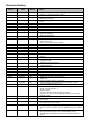
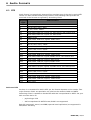
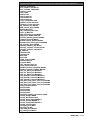
Revision History
Firmware
Version
Date
Initials
Notes
Updated sections 1.2, 1.5, 4.1
Chapter 7 “Display interface” added
Added relay support, B274
Added repeat function
Added sleep function
Described keyboard.html and added an image of the remote
control
Added error code 19 (Audio Format Not Supported)
Added setup parameter B498
Added setup parameter i680
Updated FLASH layout
Default value for URL1 is the Barix radio
Removed messages.ini
Added commands c=71 and c=72
update.ini updated
WEB UI files updated
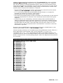
Described the display interface
Added audio peak levels
Default value of URL1 updated
Added relays 2-16
Relay 1 moved from B274 to B252
Added &Lstate dynamic mark variables 31 and 51..66
Added priority message volume B243
Added dynamic marks 32, 33 and 34
Added dynamic mark &LSetup 23
MTELL renamed to Barimon
Added command port option to B498
Section 3 rewritten, added serial command interface
Added Factory Defaults and B241 and B242 (min and max
volume)
Setup.cgi section rewritten.
Added section WEB server together with a description of the
mimetype.ini file
Added time of the last error
Default stream check period changed from 10-180s to 1-30s
(feature #052.08)
Setup version increased to 1.2
Removed MMS and MMST
Frame based buffering
&Lstate variable nr. 38
New frame bufferparameters in Barimon report
New UI files
Added TCP and UDP command ports
new parameter "usb_backup_switch_immediately" in
update.ini
balance as B245 and b= command
Volume interface changed from 5% to 1% steps. Setup
version changed from 1.2 to 1.3.
Added “V=” command (volume in 1% steps)
Barimon alarm sent also on stream recovery
Default channel number 1
AD gain settings
Volume Offset
Currently decoded audio format &Lstate(42
URL protocols, Line-in and triggered playback in Streaming
Settings section
New parameter priority volume control
Updated remote-update example, using new parameter
volume_100
Added file inputs.txt and dynamic mark to read I/O status
Relay while priority message
Added IPAM type as dynamic mark 45
Flash memory layout updated (chapter 2.2)
Remote Firmware Update requires 2MB Flash devices (chapter
7)
2MB requirement for remote FW update
EOL required at the end of the remote-update ini file.
Extra &Lstate parameters 46 and 47 for remote firmware
update.
B2.03
14.05.2008
PK
A2.04
A2.05
06.06.2008
09.06.2008
PK
PK
15.09.2008
PK
30.09.2008
05.01.2009
09.01.2009
12.01.2009
19.01.2009
21.01.2009
29.01.2009
PK
PK
PK
PK
PK
PK
PK
30.01.2009
07.03.2009
31.03.2009
PK
PK
PK
01.04.2009
08.04.2009
17.04.2009
18.04.2009
17.06.2009
24.06.2009
13.07.2009
30.07.2009
PK
PK
PK
PK
PK
PK
PK
PK
31.07.2009
05.08.2009
PK
PK
A2.11
21.08.2009
PK
A2.12
A2.13
A2.14
17.09.2009
29.12.2009
03/01/2010
04/06/10
04/22/10
04/27/10
10/18/10
11/01/10
PK
PK
PK
PK
PK
PK
PK
PK
11/09/10
PK
A2.24
12/03/10
30/05/11
PK
PK
A2.26
02.28
09/06/11
11/23/11
PK
PK
02.29
18/01/12
PK
03.02
02/29/12
04/05/12
PK
PK
03.05
17.09.12
PK
A2.06
A2.08
A2.09
A2.20
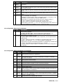
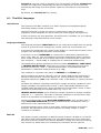
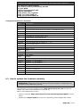
Firmware
Version
3.08
3.10
Date
10.01.13
08.03.13
Initials
Notes
PK
PK
Setup parameter B250 – audio buffer size.
Audio formats, RTP/AAC
Added configurable parameters SNMP SysName and
SysLocation to Setup and into remote configuration.
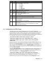
Table of Contents
1
Introduction............................................................................................................ 7
1.1 About the “Streaming Client” firmware......................................................................................... 7
1.2 Features........................................................................................................................................ 7
1.3 Installing the device...................................................................................................................... 7
1.4 Additional documents.................................................................................................................... 8
1.5 Preloaded Firmware....................................................................................................................... 8
1.6 About this Technical Documentation............................................................................................. 8
Links to chapters............................................................................................................................ 8
Bookmarks pane in Adobe Acrobat.................................................................................................8
Chapter overview........................................................................................................................... 8
2
Memory organization............................................................................................. 10
2.1 Serial Rescue Kit / Web Update................................................................................................... 10
2.2 Flash Memory usage.................................................................................................................... 10
Flash memory usage table........................................................................................................... 10
2.3 Configuration storage (EEPROM)................................................................................................. 11
Factory defaults using Serial Rescue Kit.......................................................................................11
Factory defaults using Web Update.............................................................................................. 11
Configuration storage usage........................................................................................................ 11
3
Application Programming Interface (API)................................................................19
3.1 Command interface..................................................................................................................... 19
3.2 CGI command interface............................................................................................................... 19
3.3 Serial command interface............................................................................................................ 19
3.4 TCP command interface............................................................................................................... 20
3.5 UDP command interface.............................................................................................................. 20
3.6 List of commands........................................................................................................................ 20
4
WEB User interface................................................................................................ 23
4.1 User Interface Development Kit .................................................................................................. 23
Web2cob tool............................................................................................................................... 23
Original UI Files............................................................................................................................ 23
4.2 The WEB Server........................................................................................................................... 26
Mimetype.ini................................................................................................................................. 26
Backwards compatibility............................................................................................................... 26
4.3 Dynamic Web Pages.................................................................................................................... 27
Initial Dynamic Mark..................................................................................................................... 27
Syntax of Dynamic Marks............................................................................................................. 27
List of Dynamic Mark IDs for &LSetup.......................................................................................... 28
List of Dynamic Mark IDs for &LState........................................................................................... 29
List of Dynamic Mark Parameters for &LState..............................................................................29
4.4 Configuration via HTML Pages..................................................................................................... 31
Examples...................................................................................................................................... 32
Form element names................................................................................................................... 33
5
Streaming Settings................................................................................................ 34
5.1 Streaming URLs........................................................................................................................... 34
5.2 URL Variable Substitution............................................................................................................ 35
5.3 Triggered Message Playback....................................................................................................... 35
6
Audio Formats....................................................................................................... 37
6.1 RTP.............................................................................................................................................. 37
AAC over RTP............................................................................................................................... 37
7
IR control interface................................................................................................ 38
IR Buttons..................................................................................................................................... 38
Channel Selection......................................................................................................................... 38
Stand-by Mode............................................................................................................................. 38
File “remote.ini”........................................................................................................................... 38
Barix IR Remote Control Button Assignment................................................................................40
8
Display interface................................................................................................... 41
Song information.......................................................................................................................... 41
Channel names............................................................................................................................ 41
8.1 The DILL Language...................................................................................................................... 42
Introduction.................................................................................................................................. 42
Language elements...................................................................................................................... 42
DDF file........................................................................................................................................ 42
Program execution....................................................................................................................... 43
Special commands....................................................................................................................... 43
Display control............................................................................................................................. 43
Commands................................................................................................................................... 44
Boolean expressions..................................................................................................................... 46
Variables...................................................................................................................................... 46
Function calls............................................................................................................................... 47
9
Remote Configuration and Update interface............................................................49
9.1 Configuration parameters............................................................................................................ 49
Update URL.................................................................................................................................. 49
Remote Update Period................................................................................................................ 49
9.2 Configuration Meta File................................................................................................................ 49
Keywords...................................................................................................................................... 49
Control Commands....................................................................................................................... 49
Config values................................................................................................................................ 49
Execution procedure.................................................................................................................... 49
Update file request....................................................................................................................... 50
File “update.ini”........................................................................................................................... 50
Configuration Meta File Grammar................................................................................................. 52
9.3 How to update the firmware remotely......................................................................................... 52
9.4 How to configure the device remotely......................................................................................... 53
Device dependent update files..................................................................................................... 53
10
Remote monitoring interface................................................................................55
10.1 Barimon Remote Monitoring...................................................................................................... 55
Barimon periodic report................................................................................................................ 55
Requesting Barimon report over UDP........................................................................................... 56
10.2 Own Monitoring Server using Barimon protocol.........................................................................56
Configuration Parameters for Barimon periodic report.................................................................56
Example “submit.php” ................................................................................................................ 57
10.3 SNMP Remote Monitoring.......................................................................................................... 57
SNMP trap sending....................................................................................................................... 57
SNMP querying............................................................................................................................. 57
File “BARIXAUDIOSNMP.MIB”........................................................................................................ 57
10.4 Error Code Listing...................................................................................................................... 61
11
Legal Information................................................................................................ 63
1 Introduction
1.1 About the “Streaming Client” firmware
The “Streaming Client” firmware was designed for the professional field: audio
bridging, audio distribution, in store and standalone applications.
It is capable of playing MP3 files using various protocols. Up to three sources can be
defined (both streaming over network and playing from a local USB storage) for
streaming with automatic failover.
Thanks to easy remote control and monitoring the “Streaming Client” firmware can
be used on Barix devices to build a manageable distributed audio network.
The standalone capability (playing from external USB or internal flash memory,
without network connection) allows the use of the Barix Exstreamer 100 or the
Barix Exstreamer 200 as a simple MP3 player with automatic start on power up.
1.2 Features
• Plays MP3 streams from network (HTTP, BRTP, RTP) and M3U playlists (HTTP)
• Plays MP3 files and M3U playlists from external USB memory
*
• Supports authentication (HTTP, Shoutcast, Icecast)
• Shoutcast meta-data displayed on hardware featuring LCD
• Supports up to 3 sources with automatic failover
• Control and configuration using a standard web browser
• Supports automatic remote update of settings, configuration and firmware
• Monitoring using SNMP and Barimon (HTTP, UDP)
• Supports the Barix IR Remote Control
• Automatic network configuration (BOOTP, DHCP, AutoIP and IPzator) as well as
manual static IP configuration
• Features SonicIP ® announcing the IP address on power up over the audio
outputs
• Supports proxy server (HTTP proxy support)
• Autoplay functions plays all audio files without playlist (standalone mode)
• Stand-by mode to stop playback and save network bandwidth
• Priority port to receive high-priority RTP audio messages
• Serial gateway to transmit RS232 data to a remote location
• Serial command interface
• Configurable reset button function
• Background monitoring of playlists during playback and automatic reconnect on
change
1.3 Installing the device
For the installation of the Barix Exstreamer 100 or the Barix Exstreamer 200 please
refer to the corresponding “Quick Install Guide”.
A printed version is included in the box and can also be downloaded from our site
www.barix.com.
For the installation of the Barix IP Audio Module or the Barix IP Audio Module 200
please refer to the corresponding “Development Specification” which can be
downloaded from our site www.barix.com.
* These features are not available for legacy devices (Exstreamer, Exstreamer Wireless, Exstreamer
Digital and Exstreamer Gold).
BARIX AG | 7/63
1.4 Additional documents
Technical specifications can be found in the corresponding product sheet which can
be downloaded from our site www.barix.com.
For configuration information please download the “Streaming Client Manual” from
our website.
1.5 Preloaded Firmware
Barix preloads all Exstreamer family devices, except for the Exstreamer 110, with
the “Standard” firmware version, which suits most home and consumer
applications.
Before continuing with this technical documentation the firmware has to be
changed from “Standard” to “Streaming Client” firmware.
Please follow the steps in chapter “Updating the Firmware” of the “Streaming Client
Manual” in order to change the firmware.
1.6 About this Technical Documentation
Links to chapters
References to chapters (e.g. X Chapter name) are red and underlined and serve as
direct links when viewed in Adobe Acrobat Viewer.
Click on the link to jump to the referenced chapter, click on the left arrow icon to
jump back to where you came from.
Bookmarks pane in Adobe Acrobat
The complete “Table of Contents” is available in Adobe Acrobat Viewer.
Click on the “Bookmarks” pane tab on the left side of Adobe Acrobat Viewer to open
it.
Click on any bookmark to directly jump to the corresponding part of the manual.
Chapter overview
This technical documentation is divided into the following chapters:
• 2 Memory organization (explaining the use of the Flash memory and the EEPROM
configuration memory)
• 3 Application Programming Interface (API) (explaining how to control the device
using CGI web commands )
• 4 WEB User interface (explaining the User Interface functionality and how to
customize it)
•
Advanced (explaining the functionality of URL Variable substitution)
• 7 IR control interface (explaining the functionality IR Remote control interface)
• 8 Display interface (explaining the use of the LCD, where available, for additional
device status information)
• 9 Remote Configuration and Update interface (explaining configuration and
firmware update via a remote webserver)
• 10 Remote monitoring interface (explaining the remote monitoring capabilities
using a Barimon or own monitoring server and explaining the SNMP interface
capabilities and the required MIB file)
BARIX AG | 8/63
2 Memory organization
2.1 Serial Rescue Kit / Web Update
Two different procedures exist to upload the “Streaming Client” firmware into the
device:
The “Serial Rescue Kit” using the serial cable will upload the firmware files, the boot
loader and the “factory defaults configuration” which will erase the current
configuration. The “Web update” using a browser will upload the firmware files and
the “factory defaults configuration” but will not alter the current configuration. For
factory defaults and memory usage details see the following two sections.
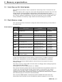
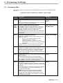
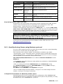
2.2 Flash Memory usage
The “Streaming Client” firmware is using the built-in Flash memory as described in
the table below.
Flash memory usage table
Page /
Target
File name
Content
Address (Rescue
Kit)
8K
(WEB0)
stream.rom
Firmware
0xC00000
WEB1
fs.bin
USB file system
0xC10000
WEB2
sg.bin
Audio and Utility library 0xC20000
WEB3
sg.bin continued
Audio and Utility library Continued
(0xC30000)
WEB4
bclio.bin
IO Driver
0xC40000
WEB5
streamapp.cob
Web Application and
SonicIP Resources
0xC50000
WEB6
streamapp.cob continued
Web Application and
SonicIP Resources
continued
(0xC60000)
WEB7
streamapp.cob continued
Web Application and
SonicIP Resources
continued
(0xC70000)
WEB8...
WEB14
Unused
Unused
0xC80000...0xCE0
000
WEB15... reserved for remote
WEB30
firmware update
0xCF0000...0xDE0
000
A page uses 64 kilobytes of flash memory. Flash memory of 2MB is assumed.
Please note: 0xC00000 is mirrored to 0xE00000 and 0xD00000 to 0xF00000.
Both update procedures (Web update & Serial Rescue Kit) respect the above
memory usage.
The above memory usage table must be used accordingly when loading single files
using advanced web update.
The target has to be in capital letters (i.e. WEB4).
The remote firmware update feature splits the FLASH into two partitions where one
contains the running firmware image and the other is reserved for the remote
upload and is normally empty. The partitions are automatically switched. The
complete firmware with all extension modules and resources must fit into 14 pages
(the fifteenth page is reserved for the bootloader).
The compound WEB update overwrites the whole FLASH with and stores the
Streaming Client firmware into the FLASH first partition (pages 0 to 14). If the
BARIX AG | 9/63
advanced WEB upload method is used together with the remote firmware update,
the individual pages must be loaded carefully because the firmware can be
currently placed in the second partition (pages 15 to 30).
2.3 Configuration storage (EEPROM)
The current configuration is stored in a non-volatile memory (EEPROM). To change
the current configuration use the web user interface and hit the “Apply” button to
store it into the EEPROM as described in the “Streaming Client Manual” in chapter
“Device Configuration”.
Factory defaults using Serial Rescue Kit
The EEPROM is overwritten by the “factory defaults configuration” when applying
the “Serial Rescue Kit” using the binary file config.bin which is stored in the folder
“update_rescue”. This file can be edited with a hex editor. Consult the
“configuration memory usage” table carefully before you make any changes.
Factory defaults using Web Update
The “factory defaults configuration” binary file config.bin is contained in the file
streamapp.cob which is loaded into the flash memory (not the EEPROM!) when
applying the “Web Update”. To apply the “factory defaults configuration” the reset
button has to be pushed for about 10 seconds.
The file config.bin can be edited with a hex editor. Consult the “configuration
memory usage” table carefully before you make any changes. Before uploading the
folder streamapp (residing in folder webuidevkit) has to be packed into the file
streamapp.cob using the tool web2cob.exe. The file is loaded to the EEPROM as
factory default when the reset button is pushed for about 10 seconds. For more
details see chapter 4 WEB User interface.
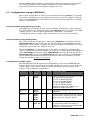
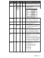
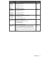
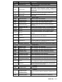
Configuration storage usage
The following table shows where the configuration is stored in the EEPROM. The
column “Byte” shows the offset as a decimal number. The column “Len” shows the
length in Bytes. The column “Default” shows the default value as stored in the
original “factory defaults configuration”.
Parameter Byte
Dynamic Len
Name
Default Short Description
Own IP
0
B0,B1,
B2,B3
4
0.0.0.0 Static IP address of the device. 0.0.0.0
for automatic assignment
0.0.1.0 to disable AutoIP
0.0.2.0 to disable BOOTP
0.0.4.0 to disable DHCP
0.0.8.0 to disable IPzator
add these special IP addresses to
disable multiple protocols
Gateway
IP
4
B4,B5,
B6,B7
4
0.0.0.0 Gateway IP address. 0.0.0.0 for no
gateway
Netmask
8
N8B0,
N8B1,
N8B2,
N8B3
1
0
DNS 1
64
B64,B65, 4
B66, B67
Subnet mask. The value is the count of
the zero bits counted from the lowest
byte. (eg. 8 for 255.255.255.0)
0.0.0.0 Primary DNS IP address. Set to 0.0.0.0
to get primary DNS from DHCP, if
DHCP is configured, or to disable DNS,
if DHCP is not configured.
BARIX AG | 10/63
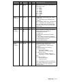
Parameter Byte
Dynamic Len
Name
Default Short Description
DNS 2
68
B68,
4
B69,
B70, B71
0.0.0.0 Alternative DNS IP address. 0.0.0.0
here always disables secondary DNS
IFMODE0
80
B80b0-1, 1
B80b2-3,
B80b4-5,
B80b6-7
or B80
0x4C
Serial port 0 settings
Definition of the bits in that byte for
the serial port 0:
Function 7 6 5 4 3 2 1 0
RS232-C
0 0
7 Bit
1 0
8 Bit
1 1
no parity
0 0
even
1 1
parity
odd
0 1
parity
1 Stopbit 0 1
2 Stopbit 1 1
BAUDRATE 81
0
B81
1
2
Baudrate for the serial port 0. (7 =
300, 6 = 600, 5 = 1200, 4 = 2400, 3 =
4800, 2 = 9600, 1 = 19200, 0 =
38400, 9 = 57600, 8 = 115200)
FLOWCON 82
TROL0
B82
1
0
Flow control for the serial port 0. (0 =
no, 1= Software XON/XOFF, 2 =
Hardware RTS/CTS)
GATEWAYD 88
STIP
B88, B89,
B90, B91
4
0.0.0.0
Serial Gateway destination IP address for
active serial gateway. If this IP address is
0.0.0.0, then the serial gateway operates in
passive (listening) mode. See also
GATEWAYPORT below.
GATEWAYP
ORT
92
W92
2
0
Serial Gateway Port. For active serial
gateway this is the destination port to
connect to (source port is random). For
passive serial gateway it's the listening
port. If the port number is 0, the serial
gateway function is completely disabled.
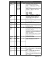
BOOTTAR
GET
94
W94
2
“2K”
If this parameter is set to 0x0000 the
firmware with the highest version will
be started.
If this parameter is set to a value
highest version of the firmware with
this target will be started. If the target
is 3Q (like for the standard Exstreamer
firmware) the value will be the ASCII
code of this two characters 0x5133.
The first character is the high byte.
Security
settings
97
B97
1
0
Bit 0: not used
Bit 1: disable factory defaults by
button (0=enabled)
Bit 2: disable remote update
functionality (0=enabled)
Bit 3: not used
Bit 4: not used
Bit 5: not used
Bit 6: not used
Bit 7: not used
See also “Reset Button Function” B276
BARIX AG | 11/63
Parameter Byte
Dynamic Len
Name
DHCP Host 98
Name
S98
16
Version
Major
116
B116
1
1
Version Major value (do not change)
Version
Minor
117
B117
1
3
Version Minor value (do not change)
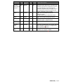
Setupex
Length
120
W120
2
894
Length of the extended setup (always
894)
Password
Level 0
122
S122
8
Password reserved for future use,
stored as a MD5 hash (first 8 bytes), all
0 means no password
Password
Level 1
130
S130
8
Password used for viewing and
changing the configuration, stored as a
MD5 hash (first 8 bytes) all 0 means
no password
Password
Level 2
138
S138
8
Password reserved for future use,
stored as a MD5 hash (first 8 bytes), all
0 means no password
Password
Level 3
146
S146
8
Password reserved for future use,
stored as a MD5 hash (first 8 bytes), all
0 means no password
Password
Level 4
154
S154
8
SNMP read-only community.
Stored as a MD5 hash (first 8 bytes).
All 0 means no protection, i.e. the
device accepts any community.
Password
Level 5
162
S162
8
Password reserved for future use,
stored as a MD5 hash (first 8 bytes), all
0 means no password
Priority
Volume
Control
240
B240
1
0
0 = use fixed priority volume “Priority
volume” (see below), disable volume
control during priority message
1 = same volume as the stream, allow
volume control during priority
playback
Minimum
Volume
241
B241
1
0
Minimum volume allowed to be set by
the user. This is also the mute volume.
In 1% steps. Default 0%
Maximum
Volume
242
B242
1
100
Maximum volume allowed to be set by
the user. In 1% steps. Default 100%
Priority
volume
243
B243
1
50
Priority message volume in 1% steps.
Default: 50%
Volume
244
B244
1
50
Volume in 1% steps. Default: 50%
Balance
245
B245
1
0
Balance: -10...+10
-10 = full left
0 = center
+10 = full right
Bass
246
B246
1
0
Bass: -10..+10
Treble
247
B247
1
0
Treble: -10..+10
Reserved
248
1
Default Short Description
Name of the device sent in DHCP
request. If not set, automatically
generated name based on device's
MAC address is sent. The string
includes terminating zero.
Reserved for further audio parameters
BARIX AG | 12/63
Parameter Byte
Dynamic Len
Name
Default Short Description
A/D Gain
249
B249
1
64
Attenuation of the line input signal on
Exstreamer 205:
0 = mute
1 = -36dB
2 = -30dB
4 = -24dB
8 = -18dB
16 = -12dB
32 = -6dB
64 = 0dB
Audio
250
buffer size
B250
1
0
Logarithmic audio buffer size. Valid
values are:
16 = high buffer size: 65536 bytes
(default)
15 = medium buffer size: 32768 bytes
14 = low buffer size: 16384 bytes
0 or any other value are interpreted
the same way as the value 16 (high
buffer size).
Reserved
251
Relay
Function
252
Reserved
268
Reset
Button
Function
276
1
B252..B2 16
67
B276
Reserved for further audio parameters
0
8
0
1
0
Relay function for relays 1-16 (where
supported by the hardware):
0: disabled (inactive)
1: always on
2: relay while operating (off while
stand-by)
3: relay while non-priority playback
4: control by the source (via Shoutcast
metadata/RTP extension)
5: relay while priority
Configures the function of the reset
button, possible values are:
0: normal function – device reset
(default)
1: reset disabled (no function)
2: playlist control
short press SONG+,
long press (>=1sec) SONG3: channel control
short press CHAN+ and play
long press (>=1sec) CHAN- and
play
4: volume control
short press VOL+
long press VOLThis configuration does not influence
the “Factory Defaults” function of the
reset button, see also “Security
Settings” B97
BARIX AG | 13/63
Parameter Byte
Dynamic Len
Name
Default Short Description
Media
277
Configurat
ion
B277b0,
B277b1,
B277b2,
B277b3,
B277b4,
B277b5,
B277b6,
B277b7
1
0x02
This values can be added (the function
is activated by setting the bit):
0x01: 0 – shuffle off, 1 – shuffle on
0x02: 0 – USB Autoplay off, 1 – USB
Autoplay on
0x04: 0 – USB streaming: finish file
before switching back to higher priority
stream, 1 – switch as soon as the
stream is available
0x08: not used
0x10: not used
0x20: not used
0x40: not used
0x80: 0 – SonicIP on, 1 – SonicIP off
Remote
Update
File
Version
278
W278
2
0
Version of the last update-meta file
processed. Internally used by the
firmware. For further details see
chapter 9 Remote Configuration and
Update interface.
Web
Server
Port
283
W283
2
0
USB Serial
Number
285
D285
RTP
Priority
Port
289
W289
Priority
buffer
level
291
Channel
Number
Port on which built-in web server is
running. Range: 0...65535 (0 stands
for standard port 80)
Used for playlist position memory
4
RTP port for receiving priority
messages. Range: 1...65535, 0 means
disabled (default)
2
0
W291
2
300
Decoding latency with RTP protocol, in
milliseconds. Theoretical range is from
0 to about 16000 ms.
The minimum value is limited by a 2kB
DSP buffer, which has to be always full.
The maximum value is limited by the
64kB device buffer.
When calculating the latency the jitter
and possible lost frames have to be
taken into account.
293
W293
2
1
Last channel number
URL1
Playlist
Position
295
W295
2
0
Index (starting from 0) of the last
playlist entry played on URLx.
URL2
Playlist
Position
297
W297
2
0
URL3
Playlist
Position
299
W299
2
0
URL1
Flags
301
B301
1
0
URL2
Flags
302
B302
1
0
URL3
Flags
303
B303
1
0
URL Flags:
Bit 0: 1= increase the playlist position
on reconnect/reboot, 0 = start with the
same position
Bit 1: 1= refresh URL even when it's
currently playing and reconnect if
playlist content changes
Bit 2: 1=stop playlist playing after the
first error, 0=stop only if all entries fail
Bit 3: unused
BARIX AG | 14/63
Parameter Byte
Dynamic Len
Name
Default Short Description
Bit
Bit
Bit
Bit
SNMP
SysName
4:
5:
6:
7:
unused
unused
unused
unused
444
S444
18
SNMP System Name.
Default is empty.
SNMP
462
SysLocatio
n
S462
18
SNMP System Location.
Default is empty.
Target
Page
480
S480
17
This is a software field used by
setup.cgi. It contains the target page
to be displayed after device reboot. I.e.
in rebooting.html.
IR Source
497
B497
1
1
IR receiver type:
0= Serial IR Dongle
1= Built-in IR receiver
Serial port 498
usage
B498
1
1
Defines for what the serial port is
used:
0 = serial GW
1 = VSC panel
2 = command port
UDP
command
port
503
W503
2
0
Receive port for UDP commands, 0 =
disabled
TCP
command
port
505
W505
2
0
Receive port for TCP commands, 0 =
disabled
TCP
command
port
timeout
507
W507
2
0
Timeout in seconds on the TCP
command port. If there is no activity
(no data coming in) for the defined
period then the TCP connection is
closed by the Barix unit.
Use 0 to disable (Barix device never
closes the connection).
RTP
latency
509
W509
2
600
Decoding latency with RTP protocol, in
milliseconds. Theoretical range is from
0 to about 16000 ms.
The minimum value is limited by a 2kB
DSP buffer, which has to be always full.
The maximum value is limited by the
64kB device buffer.
When calculating the latency the jitter
and possible lost frames have to be
taken into account.
Preset
515
W515
2
0
User-specific storage, this parameter
has no functionality. It can be used by
the user for the web interface.
S517
32
User-Agen 517
t
HTTP/Shoutcast/Icecast User-Agent
string
If empty, default Streaming Client
identification is used.
BARIX AG | 15/63
Parameter Byte
Dynamic Len
Name
Default Short Description
Triggered
Playlist
570
S570
100
Volume
Offset
677
B677
1
0
Output volume of the device can be
offset to adjust the encoder-decoder
path to 0dB.
The Volume Offset is in dB units,
stored in Setup as the value+128. E.g.
+3dB offset is stored in Setup as 131.
The Setup value 0 has a special
meaning “auto”. "Auto" presets the
gain automatically according to the
hardware.
Decoding 680
Speed
Correction
i680
2
0
Decoding speed correction factor in
ppm (parts per million). This value is
signed and allows fine tuning of the
playback speed.
A negative correction slows down the
decoder, a positive value speeds up
the decoder.
NOTE: On Exstreamer 100, 110 and
200 a 48kHz audio stream/file can not
be speeded up any more (can be only
slowed down).
Maximum
Bitrate
682
W682
2
0
Maximum desired bitrate in kbps for
multi-bitrate streams.
0 (default) means receive the highest
available.
UDP
Reporting
port
684
W684
2
0
UDP port where the device reports its
Barimon status. 0 means disabled.
SNMP
Target
Trap IP
address
686
B686,
B687,
B688,
B689
4
0.0.0.0 SNMP Target IP (0.0.0.0 for disable
SNMP)
Update
Period
690
W690
2
720
Period in minutes how often to poll
update information from a remote
server. Range 1...1000. For further
details see chapter 9 Remote
Configuration and Update interface.
BARIMON
Period
692
W692
2
5
Period in minutes how often to send
device's status to the BARIMON server.
Allowed values are in range 1...1000.
For further details see chapter MTELL.
Stream
Check
Period
694
W694
2
1
Period in seconds how often the
stream sources are checked for
availability. Allowed values are in
range 1...65535
Path to remotely triggered playlist.
One file from the playlist is played and
then playback returns to the standard
URL1-3. Has lower priority than Priority
message.
Can be used i.e. for advertisement.
See section 5.3 Triggered Message
Playback for more details.
BARIX AG | 16/63
Parameter Byte
Dynamic Len
Name
Default Short Description
Stream
696
Max Check
Period
W696
2
30
URL1
700
S700
100
URL of first streaming source
Default value:
”http://www.barix.com/radio.m3u”
URL2
800
S800
100
URL of second streaming source
URL3
900
S900
100
URL of third streaming source
Default value: “playlist.m3u”
100
URL of HTTP proxy server.
100
Remote update URL. For further details
see chapter 9 Remote Configuration
and Update interface.
100
URL of BARIMON server. For further
details see chapter MTELL.
HTTP
1000 S1000
proxy URL
Update
URL
BARIMON
URL
1100 S1100
1200
S1200
Maximal time period (in seconds) the
stream sources are checked. Sources
are periodically checked and the
period is dynamically changed. This is
the maximum value the period can
reach. Default is 30 seconds.
BARIX AG | 17/63
3 Application Programming Interface (API)
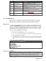
3.1 Command interface
Barix Streaming Client features a command processor with several interfaces:
Serial, TCP, UDP, CGI (HTTP) and IR remote control. The serial, TCP and UDP
command interfaces can be enabled or disabled, the CGI and IR command
interfaces are always on. Commands are processed asynchronous to the audio
stream.
The available commands are listed in section below. A general description of the
command syntax follows:
●
Commands are case sensitive
●
General syntax: <cmd> = <value>
Where <cmd> is a single ASCII letter and = is the equal sign (ASCII 0x3D)
Example: v=10 sets volume to 50%
●
Multiple commands are concatenated using & (Ampersand, ASCII 0x26).
For example, to move to next song and set volume to 60% use: c=4&v=12.
The commands will be executed from left to right in sequence (not parallel).
●
Commands from multiple sources (e.g. TCP and serial) are executed in
parallel without defined order
3.2 CGI command interface
•
Commands are passed to the rc.cgi script using the HTTP GET method
•
Example for CGI WEB commands: http://x.x.x.x/rc.cgi?c=99 (command for
RESET on Streaming Client with IP address x.x.x.x)
•
If “L=” is used a specific WEB page or file stored in the FLASH is returned in
response, otherwise a blank page is returned
•
Respect the common character set for URLs and encode “forbidden”
characters.
•
A CGI request should not exceed 1024 bytes.
•
If password is set on the unit command execution is password protected.
A valid password must be sent with the “a=” command e.g.
http://x.x.x.x/rc.cgi?c=99&a=password or within the “Authorization”
field of the HTTP request header
3.3 Serial command interface
●
The serial command interface can be enabled via the WEB UI, by default is
off
●
The first serial port is used for communication using the configured speed
and settings
●
A command sequence is terminated by one of the following characters: 0x0A
(ASCII LF), 0x0D (ASCII CR) or 0x00 (binary end of string)
●
Unless “L=” is a part of the command string an answer “OK\r\n” (ASCII 0x4F,
0x4B, 0x0D, 0x0A) is returned in case of success or “ERROR\r\n” (ASCII 0x45,
0x52, 0x52, 0x4F, 0x52, 0x0D, 0x0A) in case of an error
●
No authentication required, all commands and pages are accessible
independent whether a password is set on the unit
BARIX AG | 18/63
3.4 TCP command interface
●
The TCP command interface can be enabled via the WEB UI, by default is off
●
commands are sent to a configured TCP port, only one client can be
connected at a time
●
the connection stays open until the client closes it or is closed by the Barix
unit after configurable period of inactivity (timeout in seconds)
●
A command sequence is terminated by one of the following characters: 0x0A
(ASCII LF), 0x0D (ASCII CR) or 0x00 (binary end of string)
•
If password is set on the unit the command execution is password protected.
A valid password must be sent within each command sequence using “a=”
command, e.g.: a=password&v=10<LF>
●
Unless “L=” is a part of the command string an answer “OK\r\n” (ASCII 0x4F,
0x4B, 0x0D, 0x0A) is returned in case of success or “ERROR\r\n” (ASCII 0x45,
0x52, 0x52, 0x4F, 0x52, 0x0D, 0x0A) in case of an error (including password
mismatch)
3.5 UDP command interface
●
The UDP command interface can be enabled via the WEB UI, by default is off
●
commands are sent to a configured UDP port
●
commands are processed in sequences, there is one command sequence
per UDP packet, maximum length of a command sequence is 512 bytes
●
command sequence is either non-terminated or can be terminated by one of
the following characters: 0x0A (ASCII LF), 0x0D (ASCII CR) or 0x00 (binary
end of string)
●
command response is sent in one UDP packet to the originating IP address
and port; the source port is the UDP command port
•
If password is set on the unit the command execution is password protected.
A valid password must be sent within each command sequence using “a=”
command, e.g.: a=password&v=10<LF>
●
Unless “L=” is a part of the command string an answer “OK\r\n” (ASCII 0x4F,
0x4B, 0x0D, 0x0A) is returned in case of success or “ERROR\r\n” (ASCII 0x45,
0x52, 0x52, 0x4F, 0x52, 0x0D, 0x0A) in case of an error (including password
mismatch)
●
command response is truncated to 512 bytes
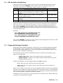
3.6 List of commands
Element
Description
CGI
command
PLAY
Restarts current stream
c=1
NEXTSONG
If current source is playlist, next song starts playing.
c=4
PREVSONG
If current source is playlist, previous song starts
playing.
c=5
SHUFFLEON
Shuffle on.
c=6
SHUFFLEOFF
Shuffle off.
c=7
MUTE
Toggle volume mute.
c=8
CHANNELINC
Increment channel number (see chapter 7 IR control
interface).
c=15
BARIX AG | 19/63
Element
Description
CGI
command
CHANNELDEC
Decrement channel number (see chapter 7 IR control
interface).
c=16
VOLUMEINC
Increment volume by 2%
c=19
VOLUMEDEC
Decrement volume by 2%
c=20
TOGGLESHUFF Toggle shuffle.
LE
c=30
CHANNELINC_2 Increment channel number in the range 0 to 99, used c=71
DIGIT
internally with VSC panel
CHANNELDEC_ Decrement channel number in the range 0 to 99,
2_DIGIT
used internally with VSC panel
c=72
TOGGLEREPEA Toggle repeat. If repeat is on, plays the current song
T
in a loop. Valid only for playlists.
c=77
DEFAULTS
Sets factory defaults (if enabled in security settings),
preserves network settings and Sonic IP.
c=94
DEVICERESET
Hard reboot of the device.
c=99
BOOTLOADER
Starts the bootloader. The application will be left. It
isn't running until the next reboot.
c=100
STANDBY
Switch the device into the stand-by mode (command
suitable for the remote management).
c=101
RESUME
Abort the stand-by mode and resume normal
operation (command suitable for the remote
management).
c=102
TOGGLESTAND Toggle the stand-by mode (suitable for the ON/OFF
BY
button on the remote IR controller)
SLEEP
c=103
Toggle sleep. If sleep function is activated, the device c=104
automatically switches into standby mode after
30min.
ICGRAPH_DISC Does the same as L=discover.txt
OVERY
Used by IC Graph to discover the device via the
command protocol.
c=65535
GETDYNFILE
The response is the dynamic file stored in a cob file
with given name.
Example: L=index.html
L=…
PASSWORD
Concatenate this command with the rest of the
a=…
command sequence if the command interface is
password protected. The password has to be added in
plain text. Optionally the password can be provided
as a part of the HTTP request header (the
“Authorization” field)
PUSHDIGIT0
PUSHDIGIT1
--PUSHDIGIT9
Push digit 0.
Push digit 1.
BASSM10
BASSM09
--BASSP00
--BASSP09
BASSP10
Set minimum bass level
set bass level to -9
Push digit 9.
set neutral bass level
set bass level to +9
set maxium bass level
r=0
r=1
--r=9
see
chapter
7 IR control
interface
B=-10
B=-9
--B=0
--B=9
B=10
BARIX AG | 20/63
Element
Description
CGI
command
BALM10
BALM09
--BALP00
--BALP09
BALP10
Set balance to full left
set balance to -9
b=-10
b=-9
--b=0
--b=9
b=10
TREBLEM10
TREBLEM09
--TREBLEP00
--TREBLEP09
TREBLEP10
Set minimum treble level
set treble level to -9
VOLUME00
VOLUME01
--VOLUME20
Set minimal volume level (volume off).
Set volume level 1.
set balance to center
set balance to +9
set balance to full right
t=-10
t=-9
--t=0
--t=9
t=10
set neutral treble level
set treble level to +9
set maxium treble level
Set maximal volume level.
One step is showed as 5%. The level 0 equals the 0%.
VOLUME_PERC Sets volume in 1% steps.
ENT
Minimal volume level (volume off).
Set volume level 1%.
Set volume level 2%.
v=0
v=1
--v=20
V=0
V=1
V=1
--V=100
Set maximal volume level.
TRIGGERED_PL Remotely triggers playback of a file on the local
AYBACK
storage. S=-1 triggers the playback of the next file
from the configured playlist. S=N, where N is an
integer number >=0, triggers playback of the N-th
file.
See section 5.3 Triggered Message Playback for more
details.
S=-1
S=0
S=1
...
BARIX AG | 21/63
4 WEB User interface
4.1 User Interface Development Kit
With the “User Interface Development Kit” you can design your own web pages
(skin) and modify the answers to your needs.
The “UI Development Kit” is included in the “Streaming Client Update Kit” which is
available on www.barix.com.
Change to the contained folder uidevkit.
The folder streamapp holds the original HTML files you need for the web pages,
the answer text files, lookup files (ini), graphics and sounds as well as the default
configuration file config.bin.
You can simply edit these files and/or add new ones.
Note: Filenames must not start with rc.cgi or setup.cgi.
Web2cob tool
To generate the streamapp.cob file start the batch streamapp.bat which uses
the packaging tool web2cob.exe.
Only .cob files up to 192 kilobytes are supported by the Streaming Client.
For the upload of the .cob file to the device, go to the configuration page of the
device and click on the button ”Update”.
After the device has rebooted and the update page appears, click on “Advanced
Update”.
Enter the correct Target (check the flash memory usage table) in upper case letters.
Select the cob file you want to upload and hit the “OK” button.
Click on the “Upload” button.
Rules:
• If you upload a .cob file to already used pages the current content will be
overwritten
• The web server in the device sees all the targets (.cob files) as one directory
• If two files in different .cob files have the same name then the one from the lower
page is chosen.
After the upload reboot the device and reload the modified page in the browser to
see the changes.
Depending on the browser's cache strategy, sometimes it's needed to close and
reopen the browser to see the changes.
Original UI Files
The web interface (and the firmware) need at least the following files (more
example files might be included):
Type
Filename.extension
Description
Styles
CSS
basic.css
Generic font settings for defaults, reboot, update
and status pages
CSS
help.css
Styles for the help column (right hand column)
CSS
menu.css
Styles for the configuration menu (left hand
column)
CSS
settings.css
Styles for the configuration forms (middle
column)
BARIX AG | 22/63
Type
Filename.extension
Description
CSS
vumeter.css
Style for VU-meter on the home page
Basic frameset
HTML
index.html
Main page of the web server, frameset including
the frames: menu, uifstatus, empty. “empty” is a
hidden frame that receives the answer of the CGI
commands
HTML
menu.html
Horizontal menu and Streaming Client logo
frame on the top of the page
Image
barix.png
Barix logo
“Home” page
HTML
uifstatus.html
“Home” page: the frameset
HTML
uihstatus.html
“Home” page: the help (right hand column)
HTML
uistatus.html
“Home” page: the runtime device status
HTML
keyboard.html
“Home” page: the device control (left hand
column)
Image
remote_512.jpg
Image of the remote control – for keyboard.html
Image
o0.gif
Relay status indicator: inactive (gray square)
Image
o1.gif
Relay status indicator: active (green square)
Image
o9.gif
Relay status indicator: not available (white
square)
Javascript cmd.js
Scripts to send commands from remote control
(keyboard.html) to the device.
Javascript update.js
Scripts for background update of the “Home”
page
Javascript vumeter.js
VU-meter object for graphical display of peak
levels, buffer level and volume.
Text
Realtime status parameters fetched by update.js
realtime_status.txt
Configuration
HTML
uifbasic.html
Basic Settings: the frameset
HTML
uibasic.html
Basic Settings: the form with parameters
HTML
uihbasic.html
Basic Settings: the help (right hand column)
HTML
uimbasic.html
Basic Settings: the menu (left hand column)
HTML
uifadvanced.html
Advanced Settings: the frameset
HTML
uiadvanced.html
Advanced Settings: the form with parameters
HTML
uihadvanced.html
Advanced Settings: the help (right hand column)
HTML
uimadvanced.html
Advanced Settings: the menu (left hand column)
Javascript util.js
Javascript functions to check the input values in
the configuration (Basic and Advanced Settings)
Javascript visual.js
Javascript functions to show/hide configuration
pages in Advanced Settings
Logout
HTML
uilogout.html
logout page
Reboot
HTML
uifreboot.html
uireboot.html
uihreboot.htmll
Page for device reboot: frameset, content and
help
HTML
rebooting.html
Page shown while the device is rebooting
BARIX AG | 23/63
Type
Filename.extension
Description
Image
4to0.gif
Countdown while the device is rebooting
HTML
uirdefaults.html
uirloader.html
uirreboot.html
uirupdate.html
Shown after pressing “apply” or during reboot of
the device
HTML
uirdefaults1.html
uirreboot1.html
Shown after the device is successfully rebooted
Update
HTML
uifupdate.html
uiupdate.html
uihupdate.html
Firmware update: frameset, content and help
HTML
update.html
Forwarding page to hide the command for the
update
HTML
uifloader.html
uihloader.html
Shown after the device comes into the
bootloader: frameset and help
Factory defaults
HTML
uifdefaults.html
uidefaults.html
uihdefaults.html
Factory defaults: frameset, content and help
Status page
HTML
ixstatus.html
Frameset for the status page
HTML
status
Status page showing all configuration and useful
run time parameters
Sonic IP files
Sound
0.mp3
Sonic IP: spoken “0”
Sound
1.mp3
Sonic IP: spoken “1”
Sound
2.mp3
Sonic IP: spoken “2”
Sound
3.mp3
Sonic IP: spoken “3”
Sound
4.mp3
Sonic IP: spoken “4”
Sound
5.mp3
Sonic IP: spoken “5”
Sound
6.mp3
Sonic IP: spoken “6”
Sound
7.mp3
Sonic IP: spoken “7”
Sound
8.mp3
Sonic IP: spoken “8”
Sound
9.mp3
Sonic IP: spoken “9”
Sound
dot.mp3
Sonic IP: spoken “dot”
Configuration and other files
Binary
config.bin
Factory default settings. The file is binary and it
is an exact mirror for the EEPROM Setup record
Text
channels.ini
textual description of channels
Text
discover.txt
File returned in answer to c=65535 command.
Used by IC Graph.
inputs.txt
File containing a comma separated list of values
of first 8 digital inputs.
Value meaning:
0 = input activated or not present
1 = input not activated
Further, for 4-state inputs:
2 = short circuit
3 = not connected
Text
BARIX AG | 24/63
Type
Filename.extension
Description
Text
mimetype.ini
MIME type database for the WEB server, see
section “The WEB Server“ below
Text
remote.ini
lookup file for IR commands, see section File
“remote.ini”
Text
SONICIPVERSION
for the version number of SonicIP
implementation
Text
STREAMAPPVERSION
for the version number and the history of
Streaming Client
Text
update.ini
lookup file for names used in remote controlling,
see section File “update.ini”
Text
ex110.ddf
vsc.ddf
Display definition files for Exstreamer 110/120
and VSC panel; see section Display interface
4.2 The WEB Server
The Firmware runs two WEB server processes, which by default serve incoming
HTTP requests on TCP port 80. The port number can be changed by setting the
W263 parameter in Setup (see the Web Server Port parameter on page 15).
Mimetype.ini
To return a proper MIME type for each file, a database of valid MIME types is held in
the FLASH file mimetype.ini. This text file contains a translation table from file
extension to a MIME type. The MIME type database should be updated in case new
file types are added to the WEB UI. If the file extension is not recognised, no MIME
type description is returned to the browser and it is upon the browser to interpret
the data correctly or to guess the file format.
The format of the MIME database is following:
●
each file extension/MIME type pair is on a separate line
●
lines are terminated by CR/LF (ASCII 0x0D 0x0A) or a single LF (ASCII 0x0A)
●
the file content is case-sensitive
●
a line starts with the file extension (without the leading dot and in the proper
case), followed by a single space character (ASCII 0x20) and by the MIME
type
●
the line order is not significant
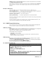
Default content of the mimetype.ini file
html text/html
gif image/gif
jpg image/jpeg
png image/png
js application/x-javascript
mp3 audio/x-mpeg
css text/css
Backwards compatibility
Please note that in the Streaming Client versions prior to 02.09 the MIME types
were statically stored in the FLASH files by the web2cob tool at the creation
time of the COB file. To avoid conflict with the previous versions the file
webuidevkit/mimetype.ini in the rescue kit must be kept empty. The new
BARIX AG | 25/63
mimetype.ini file (as described above) resides in the webuidevkit/streamapp/
directory.
4.3 Dynamic Web Pages
Web pages can include dynamic values. Dynamic Web Pages are built in HTML or
XML or in an other text file format that exclude the binary character 0x00, i.e. the
dynamic page can be an HTML file. It's possible to use scripts or everything else
allowed in the given document's file format.
Initial Dynamic Mark
In order to indicate that Web page is dynamic, it has to contain the special initial
dynamic mark &L(0,"*"); in the first 500 Bytes and before any other dynamic value
is used. The initial mark can also have decimal number as its optional third
parameter. Example of such initial mark is &L(0,“*“,1);.
The third parameter is parsed bitwise and has the following meaning:
• bit 0 is reserved for backwards compatibility and can be set to any value
• bits 1-3 select the password level (as a 3-bit number), which protects this page; 0
for no password protection
• bits 4-6 are reserved for future use and should be set to 0
• bit 7 is reserved for backwards compatibility and can be set to any value
Syntax of Dynamic Marks
Dynamic marks can be used to put dynamic values in Web pages. All dynamic
marks have the following syntax: &L<name>(<id>,<format>[,par]);
A dynamic mark always starts with &L and it is always case sensitive.
• <name> selects a group of dynamic values. Defined is the “Setup” group for all
configuration parameters and the “State” group for actual parameter states.
Remaining parameters are included in parentheses, with the right parenthesis
followed by a semicolon.
• <id> determines the desired function.
• <format> is a C-style format string (refer to the ANSI documentation).
• <par> are optional additional parameters. If additional parameters are needed, it
is mentioned in the function lists below.
Note: The string “);” is not allowed inside a dynamic mark.
To have this construct inside the format string, use “)\;“(in an unknown escape
sequence, only the '\' will be removed).
To have a “%” sign (percent sign) inside the format string, use “%%” (two signs
without space).
The whole mark is replaced by the dynamic value formatted with the <format>
string. Only one value is allowed per dynamic mark. The length of the dynamic mark
mustn't exceed 500 characters. The resulting string from the dynamic mark must
not exceed 500 characters.
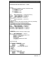
A dynamic mark can be contained in an another dynamic mark. Only one recursion
step is allowed and correct “escaping” has to be applied. Example:
&LSetup(3,"%s",419,B,!0,"<meta http-equiv=refresh
content=\"&LSetup(1,\"%u\",419)\;; url=info.html\">");
Note the special “\” before the semicolon of the dynamic mark inside. This is
because the escape sequence is interpreted as only a semicolon and is needed in
order to include the prohibited sequence “);” inside a dynamic mark.
BARIX AG | 26/63
List of Dynamic Mark IDs for &LSetup
ID
Type
Description
1
Function Print setup value
3. [par]: Address (decimal) of the value in the setup
4. [par]: Type of the value (B for unsigned byte, W for word, D for
double word, c for char/signed byte, b for bit numbered from 0 to 7,
e.g. b3 for the fourth bit). If this parameter isn't available the type
will be B.
e.g. &LSetup(1,"%08lx",315,D); as hexadecimal value with 8
characters and leading zeros
e.g. &LSetup(1,"%lu",311,D); as unsigned long decimal value
2
Function Print Netmask Byte
3. [par]:Address (decimal) of the value in the setup
4. [par]: Byte number of the Netmask IP address byte starting with 0
for the first left byte and incremented by one for the next bytes
3
Function Print string if equal
Compares a Setup entry with a value and outputs a string if the
condition is true.
3. [par]: Address (decimal) of the value in the setup
4. [par]: Type (see id 1 above)
5. [par]: value to compare. By default compared as “x=y”.
Alternatively operators !, > or < can be prepended to the value (no
spaces between) to compare “x!=y”, “x>y” or “x<y”
6. [par]: string for output if value at address is equal to 5. [par]
4
Function Print string
3. [par]: Address (decimal) of the value in the setup
5
Byte
Firmware Version Major
(integer)
6
Byte
Firmware Version Minor
(integer)
7
Byte
Bootloader Version Major
(integer)
8
Byte
Bootloader Version Minor
(integer)
9
Function Prints the version out of a standard version file in a *.cob application
3. [par]: name of the version file
4. [par]: 1 for major version number (byte), 0 for minor version
number (byte)
10
Byte
year of the firmware build (only decade), BCD coded, use %02x to
(integer) print
11
Byte
month of the firmware build, BCD coded, use %02x to print
(integer)
12
Byte
day of the firmware build, BCD coded, use %02x to print
(integer)
13
Byte
sg.bin (Audio and Utility library) Version Major
(integer)
14
Byte
sg.bin (Audio and Utility library) Version Minor
(integer)
15
Byte
fs.bin (USB file system) Version Major
(integer)
16
Byte
fs.bin (USB file system) Version Minor
(integer)
17
String
18
Byte
reserved
(integer)
sg.bin (Audio and Utility library) date of the build
BARIX AG | 27/63
ID
Type
Description
19
Byte
reserved
(integer)
20
Byte
fs.bin (USB file system) year of the build (only decade), BCD coded,
(integer) use %02x to print
21
Byte
fs.bin (USB file system) month of the build, BCD coded, use %02x to
(integer) print
22
Byte
fs.bin (USB file system) day of the build, BCD coded, use %02x to
(integer) print
23
Function Print “selected” on condition
Compares a Setup entry with a value and outputs “selected” if the
condition is true. Used in <select> WEB forms.
Parameter 2 is ignored and can be set to an empty string(“”)
3. [par]: Address (decimal) of the value in the setup
4. [par]: value to compare. By default compared as “x=y”.
Alternatively operators !, > or < can be prepended to the value (no
spaces between) to compare “x!=y”, “x>y” or “x<y”
List of Dynamic Mark IDs for &LState
ID Type
Description
1
Function Print status variable
3. [par]: Variable index, see the parameters table below, e.g.
&LState(1,"%s",12); prints out device's MAC address
2
Function Print string if condition is true
3. [par]: Index of the variable to be compared, see the parameters
table below
4. [par]: value to compare. Variable is compared with the value “if
equals”, the prefixes !, > or < can be used to change the
comparison (no spaces between allowed). If comparing variable with
a string, the string has to be quoted ( e.g. “string”)
5. [par]: string to output output if condition is true. The string has to
be quoted.
List of Dynamic Mark Parameters for &LState
Par
Type
Description
0
Boolean File system present (1 if present)
(Int.)
1
Integer
File system type (0,1,2,4,8) 0=unknown, 1=FAT12, 2=FAT16,
4=VFAT, 8=FAT32
2
Integer
File system serial number
3
Integer
Audio volume in 1% steps
4
Integer
Current stream number (or 99 for priority stream)
5
Integer
Last error (number)
6
Integer
Audio buffer level
7
Integer
Lost frames counter. Resets with every RTP stream (reconnect or
a new sequence of frames).
8
Integer
Soft error counter
9
String
Current URL ("PRIORITY" when receiving priority stream, “STDBY”
when in standby mode)
10
Integer
Stream bit rate in kilobits per second
BARIX AG | 28/63
Par
Type
Description
11
Integer
Reconnection counter
12
String
Device's MAC address (each byte separated by a colon e.g.
00:08:E1:00:3D:90)
13
String
Current IP address (four numbers, dot separated, without leading
zeroes)
14
Integer
USB device vendor ID
15
Integer
USB device product ID
16
Integer
USB device class
17
Integer
USB device subclass
18
Integer
USB interface class
19
Integer
USB interface subclass
20
Integer
USB device's max. power consumption in milliamperes
21
Boolean USB device attached
(Int.)
22
Integer
USB device capacity in kilobytes
23
Integer
Number of audio bytes transferred to the codec since playback
start
24
Integer
Current channel number
25
String
Current netmask (four numbers, dot separated, without leading
zeroes)
26
String
Current gateway address (four numbers, dot separated, without
leading zeroes)
27
String
Current address of the first nameserver (four numbers, dot
separated, without leading zeroes)
28
Integer
Hardware identification (hardware type)
29
Boolean Shuffle – current state
(Int.)
30
Boolean Repeat – current state
(Int.)
31
Integer
Number of relays supported by the current hardware
32
Integer
Player process status: 0=idle, 1=buffering, 2=playing
33
Integer
Stand-by mode: 0=off (normal operation), 1=on (stand-by)
34
String
Song title: Title of the currently played song/Name of the internet
radio station.
35
Integer
Duration of the current data in the audio buffer in milliseconds (for
RTP streaming only).
36
Integer
Number of dropped frames due to the RTP buffer management
(can indicate that the encoder runs faster than the decoder).
Resets with every RTP stream (reconnect or a new sequence of
frames).
37
Integer
Number of duplicated frames due to the RTP buffer management
(can indicate that the encoder runs slower than the decoder).
Resets with every RTP stream (reconnect or a new sequence of
frames).
38
Integer
Average duration of the data in the audio buffer in milliseconds
(for RTP streaming only).
39
Integer
System uptime in milliseconds
40
Integer
System uptime in seconds
41
Integer
Time of the occurrence of the last error (in seconds)
BARIX AG | 29/63
Par
Type
Description
42
Integer
Currently decoded audio format:
0 = MP3
1 = u-Law
2 = A-Law
3 = PCM
5 = WMA
6 = Ogg Vorbis
7 = AAC/AAC+
45
Integer
IPAM identification (module type)
46
Integer
Flash memory size in kB
47
Boolean Remote firmware update:
(Int.)
0 = not available (flash too small)
1 = available
49
Integer
Left audio output channel quasi peak in dBFS
50
Integer
Right audio output channel quasi peak in dBFS
51..6 Integer
6
Current state of the relay 1..16:
0=not activated
1=activated
9=not available on the hardware
1000 Integer
..
Access to device I/O registers. Returns the value of I/O register
“par-1000”.
See complete I/O table for each hardware device in ABCL
Technical Documentation.
4.4 Configuration via HTML Pages
The HTML pages for the device configuration use the “dynamic web page”
functionality. All of the configuration parameters are placed in HTML forms and are
transferred by the “POST” method. Input values can be checked by Javascript to
prevent incorrect values (see example below). Not all configuration parameters
have to be present in the form. It is possible to have only a part of the configuration
on a web page. The form has to start with the following three tags:
<form method=POST action=setup.cgi target="empty">
<input type="hidden" type="text" name=S480 value=__target__>
<input type="hidden" type="text" name=L value=rebooting.html
target=_top>
Please note that the above example illustrates the default WEB UI HTML set. It is
possible to design custom pages with a different structure, then the targets of the
form and of the rebooting.html as well as the answer page can be different.
After submitting the configuration the page rebooting.html is returned while the
device reboots. On error the respective error code is returned without ddisplaying
the page rebooting.html.
The page rebooting.html contains a count-down timer and a redirect back to the
configuration page. The value __target__ specifies the name of the page to be
redirected to (without the “.html”; i.e. “uisettings”) and should correspond to the
name of the HTML file. I.e. in uinetwork.html the value contains:
<input type="hidden" type="text" name=S480 value=uinetwork>
Please note that the maximum length of the target page is 16 characters. To
prevent collision and a potential damage of the configuration in case of
simultaneous access only one client is allowed to access setup.cgi at a time.
BARIX AG | 30/63
Examples
The following example shows how to implement a form field for the configuration
value of the highest byte in the 'own IP address'.
The input element name is a defined string, which has to be handled with care. The
type character B stands for an unsigned value. 0 is the address of the expected
configuration parameter . The value is a dynamic mark. The string
onChange=IPCheck(this)will call the Javascript util.js to check if the value
entered is in the range of 0 to 255.
<input name=B0 size=3 maxlength=3 value=&LSetup(1,"%u",0);
onChange=IPCheck(this)>
In the next example the name selects the configuration parameter “DHCP Host
Name”.
<input name=S98 size=15 maxlength=15 value="&LSetup(4,"%s",98);">
This example shows how to implement a form field for the configuration of the
Netmask. The names for the bytes of the Netmask are N8B0, N8B1, N8B2 and
N8B3. 8 is the address of the Netmask in the configuration memory. The value
after the B is the byte number of the byte in the Netmask starting with 0 for the
first byte at the left. This special handling for Netmask is needed because the
Netmask is stored in one byte and not like the IP address in 4 bytes. The string
onChange=netMaskCheck(this)will call the Javascript util.js to check if the
value entered is in the correct range.
<input name=N8B0 size=3 maxlength=3 value=&LSetup(2,"%u",8,0);
onChange=netMaskCheck(this)>
The next example shows how to implement a form field for the configuration of the
parameter “Volume” as a selection. If the value of the configuration parameter is
equal to the second last parameter in the dynamic mark it will be replaced by the
last parameter of the dynamic mark.
<select size=1 name=B244>
<option value=0 &Lsetup(3,"%s",244,B,0,"selected");>0</option
<option value=1 &Lsetup(3,"%s",244,B,1,"selected");>5</option>
......
<option value=19
&Lsetup(3,"%s",244,B,19,"selected");>95</option>
<option value=20
&Lsetup(3,"%s",244,B,20,"selected");>100</option>
</select><font size=2>
This example shows how to implement radio buttons for the configuration
parameter 'Sonic IP'.
The functions of the dynamic marks are equal to the example above.
<input type=radio name=B277b7 value=0&LSetup(3,"%s",277,b7,0,"
checked");>Yes
<input type=radio name=B277b7 value=1&LSetup(3,"%s",277,b7,1,"
checked");>No
To transmit the new configuration data to the device the submit input type of the
form is used.
<input type=submit value=" Apply ">
By pressing the Apply button the new configuration data will be transferred to the
device. It will store the new data to its configuration memory (EEPROM).
After this it sends the answer (see above) to the browser and reboots itself to apply
BARIX AG | 31/63
the new configuration.
Passwords are hashed (MD5) and stored in memory and set using the name Px,
where x stands for the password level.
If the password is set already, the old password must also be supplied (with the
name Px) together with the new password using the name Px.1 (P level dot one).
<tr>
&Lsetup(3,"%s",130,D,0,"
<td><b><font size=2>Set Password</font></b></td>
<td><input name=P1 size=18 maxlength=25 type=password
value=></td>
");
&Lsetup(3,"%s",130,D,!0,"
<td><b><font size=2>Old Password</font></b></td>
<td><input name=P1 size=18 maxlength=25 type=password
value=></td>
</tr>
<tr>
<td><b><font size=2>New Password</font></b></td>
<td><input name=P1.1 size=18 maxlength=25 type=password
value=></td>
</tr>
");
Px and Px.1 can also be used for remote configuration.
Form element names
• If the value is an nusigned integer (1 byte) the first character is a B.
• If the value is an IP address the first character is an I, the complete IP address can
be set as a string at once e.g.:
I0=192.168.1.2 (same as B0=192 B1=168 B2=1 B3=2) for IP address
I4=192.168.1.1 (same as B4=192 B5=168 B6=1 B7=1) for Gateway IP
address
• If the value is a Netmask the first character is an N, e.g.:
N8=255.255.255.0 (same as N8B0=255 N8B1=255 N8B2=255 N8B3=0)
• If the value is a string the first character is an S.
• If the value is a word (2 bytes) the character is a W.
• If the value is a signed integer (2 bytes) the character is an i.
• If the value is a double word (4 bytes) the first character is a D.
The following decimal value in the name is the address of the configuration
parameter (see chapter ).
To set a bit in a configuration parameter (e.g. Media Configuration) add the
character b followed by the number of the bit (starting at 0), e.g.:
b7 for the 8. bit in the byte.
Examples of names:
•
•
•
•
•
•
•
B0
B1
N8B0
N8B1
N8
S98
B277b7
first (left) byte of the configuration parameter 'own IP address'
second byte of the configuration parameter 'own IP address'
first (left) byte of the Netmask
name of the second byte of the Netmask
Netmask
DHCP Host Name
Sonic IP
BARIX AG | 32/63
5 Streaming Settings
5.1 Streaming URLs
This chapter gives an overview of the supported URL protocols. The general URL
syntax is:
protocol:// user : password @ address : port / path
Protoco Description
l
Example
file://
Local file playback (from USB storage or an SD
card).
Prefix is followed by a full path to a file or playlist.
The “file://” prefix can be omitted.
file:///music/backup
.m3u
http://
icy://
icyx://
HTTP or Shoutcast/Icecast protocol.
An IP/DNS address must be provided, usually is
followed by a path to a playlist, file or stream. A
specific TCP port can be provided, otherwise
standard port 80 is used. In case user
name/password are provided then the Streaming
Client authenticates itself to the server with the
credentials.
http://www.barix.co
m/radio.m3u
rtp://
Real-time Transport Protocol.
rtp://0.0.0.0:3030
Requires an IP/DNS address and a UDP port. The
address can be:
•
0.0.0.0 – any stream coming to the
configured port is played
•
multicast address – Streaming Client
subscribes to the multicast group and plays
the stream
unicast address – only stream from that specific
address is played (source address filtering)
brtp://
Barix extension to RTP to pull a stream.
Requires an IP/DNS address and a UDP port. The
address must be a unicast or multicast address.
The Streaming Client sends a request for RTP
stream to the configured address and then plays
the incoming stream.
null://
Special URL that does not output anything and is null://
always present.
Can be used in playlists to mute the output.
E.g. if you use dynamically generated playlists
with channels and want to make certain channels
unavailable to specific customers/devices.
line://
Line input on Exstreamer 205.
line://
This URL is “present” only if channel 0 is selected.
It passes analogue signal from the line input to the
speakers.
To use line input on channel 0 and other channels
for streaming put “line://” into URL1 and your
stream URL into URL2.
NOTE: the volume does not affect the line-in
signal strength, the signal is passed at fixed
volume level. An additional attenuation can be
configured in the “Audio and Playback” section of
the Advanced settings.
brtp://
BARIX AG | 33/63
5.2 URL Variable Substitution
URLs may contain variables which are processed and substituted by their values.
Variables have syntax $NAME$, where name consists of printable upper case
characters other than '$'. Following variable names are defined:
Name
Description
Example
MAC
Device MAC address (12 digits in hexadecimal
notation with no separators, A..F digits in capital
letters)
0008E1002B0E
IP
Device IP address (four numbers, dot separated,
without leading zeroes)
192.168.2.202
NAME
DHCP Host name (ASCII string configured in network
settings)
XSTREAM1
NUM
channel number (three digits)
003
When the device is fetching a stream then the above variables will be substituted.
This allows for specific tasks like identification, zoning and logging of the device.
The variable $NAME$ for an example could be used to group several devices to a
zone which will be supplied with different streams by the server analyzing the name
of the fetching device.
Example:
• URL1: http://myserver.com:4567/device.cgi?
zone=$NAME$&id=$MAC$&logip=$IP$
• URL1: http://myserver.com:4567/device.cgi?
channel=$NUM$&id=$MAC$&logip=$IP$
The variable $NUM$ can also be used to select numbered playlists stored on a USB
memory stick using the IR remote control.
5.3 Triggered Message Playback
Streaming Client supports playback of files from a local storage triggered remotely
via Shoutcast or by a command. This can be useful e.g. for playing local adverts,
pre-recorded announcements, etc. To use this feature enter a playlist name in the
Priority section of Advanced Settings.
The following special names in StreamTitle section of Shoutcast metadata (song
name) are recognised:
•
BARIX song next : plays next song from the priority playlist
•
BARIX song N : where N is an integer number, plays N-th file from the
playlist. N counts from 0.
Further, the playback can be triggered with the S=N command:
•
S=-1 : plays the next song from the priority playlist
•
S=N : where N is an integer number, plays N-th file from the playlist. N
counts from 0.
When such a trigger is received, the current playback (URL1-3) stops, the requested
file from the local playlist is played and when the file ends then the normal playback
(URL1-3) starts again. The triggered playback is considered as priority and therefore
also “Priority message” appears on device's display.
If Shuffle is on the “next song” command picks up a random song. The play N-th file
command is not affected by shuffle.
BARIX AG | 34/63
NOTE 1: Please note that the triggered playback cannot be interrupted, therefore
the files should be reasonably short.
NOTE 2: Triggered playback and priority message work exclusively. If a priority
message is being received then triggered playback is ignored and vice versa.
NOTE 3: It is important that Streaming Client receives the Shoutcast trigger only
once, otherwise the message will be repeated.
BARIX AG | 35/63
6 Audio Formats
6.1 RTP
Audio format is automatically detected from payload type of the the incoming RTP
stream (on both standard and priority stream). The following table provides an
overview of the formats recognized by Streaming Client.
Payload
type
Audio Format
0
μ-Law, 8bit, mono, 8kHz
8
A-Law, 8bit, mono, 8kHz
9
G.722, mono, 16kHz
10
PCM 16bit, MSB first, signed, 44.1kHz stereo, left channel first
11
PCM 16bit, MSB first, signed, 44.1kHz mono
14
MPEG audio
96
PCM, 16bit, MSB first, signed, 8kHz mono
97
μ-Law, 8bit, mono, 24kHz
98
A-Law, 8bit, mono, 24kHz
99
PCM, 16bit, MSB first, signed, 24kHz mono
100
μ-Law, 8bit, mono, 32kHz
101
A-Law, 8bit, mono, 32kHz
102
PCM, 16bit, MSB first, signed, 32kHz mono
103
PCM 16bit, MSB first, signed, 48kHz stereo, left channel first
104
PCM, 16bit, LSB first, signed, 8kHz mono
105
PCM, 16bit, LSB first, signed, 24kHz mono
106
PCM, 16bit, LSB first, signed, 32kHz mono
107
PCM 16bit, LSB first, signed, 44.1kHz stereo, left channel first
108
PCM 16bit, LSB first, signed, 48kHz stereo, left channel first
109
μ-Law, 8bit, mono, 12kHz
110
A-Law, 8bit, mono, 12kHz
111
PCM, 16bit, MSB first, signed, 12kHz mono
112
PCM, 16bit, LSB first, signed, 12kHz mono
126
AAC ADTS
AAC over RTP
As there is no standard for AAC in RTP yet, the format depends on the vendor. Two
major formats of AAC encapsulation are used on the network: RAW and ADTS.
Streaming Client is capable to decode RTP with AAC encapsulated in ADTS. Set your
AAC encoder device to:
•
payload type 126
•
AAC encapsulated in ADTS format; RAW is not supported
Both PS (parametric stereo) and SBR (spectral band replication) are supported in
AAC/AAC+ decoding.
BARIX AG | 36/63
7 IR control interface
When using IR Remote Control, make sure there is line of sight between the IR
Serial receiver and the IR Remote control.
IR Buttons
With the default factory configuration, following buttons can be used:
+VOL/-VOL – Volume up/Volume down
+SONG/-SONG – Next song/Previous song (for use with playlists)
SHUFFLE – Toggles the Shuffle Play Mode
The digit buttons (0..9) and the Play button () can be used to select channel
number.
• Buttons PLIST+ and PLIST- increase/decrease the channel number by one. To
start playback of the selected channel, the Play button has to be pressed.
• MUTE – Toggles volume mute
• ON/OFF – Toggles the Stand-by mode, see below
•
•
•
•
Channel Selection
The channel number can be used as a part of the source URL (see chapter 5.2 URL
Variable Substitution for details). The channel number is common for all three
source URLs.
Last three digits pressed within five seconds before pressing are set (from left to
right) as the channel number.
If less than three digits were pressed within five seconds before , remaining
positions (from left) are filled with the current channel number (reverted).
The channel number can be also selected by pressing PLIST+/PLIST- buttons, which
increase/decrease the channel number. After channel selection, the Play button
MUST be pressed to confirm the selection.
If multiple sources are configured, the Play button () forces playback restart from
URL1 (without checking the actual availability of URL1). This can be useful if a
backup USB stream is playing and the selected channel (higher priority network
stream) is not available – the Play button aborts the USB playback and forces the
network stream to play.
The current channel number is stored in Setup (W293) and retrieved after reboot.
Examples:
• After pressing 2,3, the channel number will be 023
• After pressing 1,4,5,6,7, the channel number will be 567
• Playing channel 15; after pressing PLIST-, PLIST-, the channel number will be 13
Stand-by Mode
To reduce network bandwidth usage and decrease associated costs for transferred
data, the device features Stand-by Mode. In this mode the device stops checking
source availability and streaming (including playback from USB source) and goes
idle. The Remote Configuration and Update function, Barimon and SNMP monitoring,
Web server, IR remote control as well as Priority message stay active in the
Stand-by Mode.
Stand-by Mode can be toggled by the ON/OFF button on the IR remote controller or
externally triggered by issuing the STANDBY or RESUME command (e.g. using the
Remote Configuration and Update function). A typical usage is e.g. in instore
applications during closing-time.
File “remote.ini”
The commands triggered by each button of the IR Remote Control can be user
defined. To upload the altered remote.ini file follow the procedure described in
BARIX AG | 37/63
chapter 4.1 User Interface Development Kit. The remote.ini file in the sub folder
webuidevkit/streamapp contains the commands for each button in a separate
line. The file format is comma-separated and the values are case-sensitive. Don't
write spaces between the separation, the only space needed is the one after the IR
coding token (“NE: “ stands for NEC coding). Every line that doesn't contain an IR
remote control command is handled as a comment.
• The first field is the IR remote control code sequence received from the remote
control (e.g. ”NE: 00FE7887“ for the play button).
• A “*“ in the second field tells the IR handler that this button is accepted for
repetition (as defined for Volume + and Volume -).
• The third field is not used and should be empty.
• The fourth and following fields contain commands. The commands can be chained
using the ampersand ('&') character. The commands are executed in the given
sequence.
• In fourth field, an “L” followed by a decimal number tells to the IR handler to
switch to numbered level for the next command. To select the command for the
corresponding level, simply add more fields to the end of the line for that button.
The fifth field is for the level 1, the sixth field is for the level 2 and so on. The
maximal level is 255. The selected level is declined after 2 seconds or when the
next button is pressed.
Example: Execute NEXTSONG command upon pushing the +SONG button on the
remote control when in level 0: ”NE: 00FE48B7,,,c=4“
Channel number selection can be implemented using IR Remote Control. There is a
three digit buffer in the firmware, that can be used with “r=x” and “c=1”
commands. The “r=0”...“r=9” commands push digits to the buffer and the “c=1”
command sets the value of the NUM variable to the current value of the buffer. The
buffer is cleared to the “currently being played” value if no digit have been pressed
for 5 seconds.
Excerpt of the remote.ini file contained in the “Streaming Client Update Kit”
Exstreamer Remote Control NEC 00FE
NE: 00FE7887,,,c=1
NE: 00FE08F7,,,c=2
NE: 00FED827,,,c=3
NE: 00FE48B7,,,c=4
NE: 00FE6897,,,c=5
NE: 00FEF807,,,c=8
NE: 00FE00FF,,,c=15
NE: 00FEB04F,,,c=16
NE: 00FEA857,*,,c=19
NE: 00FEC837,*,,c=20
NE: 00FEB847,,,c=30
NE: 00FE38C7,,,c=77
NE: 00FE30CF,,,r=0
NE: 00FE40BF,,,r=1
NE: 00FEC03F,,,r=2
NE: 00FE20DF,,,r=3
NE: 00FEA05F,,,r=4
NE: 00FE609F,,,r=5
NE: 00FEE01F,,,r=6
NE: 00FE10EF,,,r=7
NE: 00FE906F,,,r=8
NE: 00FE50AF,,,r=9
NE: 00FED02F,,,s=
NE: 00FE8877,,,c=104
NE: 00FE807F,,,c=103
BARIX AG | 38/63
Barix IR Remote Control Button Assignment
Button
IR code sequence
Button
IR code sequence
0
NE: 00FE30CF
*
NE: 00FED02F
1
NE: 00FE40BF
#
NE: 00FE8877
2
NE: 00FEC03F
+ VOL
NE: 00FEA857
3
NE: 00FE20DF
- VOL
NE: 00FEC837
4
NE: 00FEA05F
+ SONG
NE: 00FE48B7
5
NE: 00FE609F
- SONG
NE: 00FE6897
6
NE: 00FEE01F
MUTE
NE: 00FEF807
7
NE: 00FE10EF
ON/OFF
NE: 00FE807F
8
NE: 00FE906F
PLIST +
NE: 00FE00FF
9
NE: 00FE50AF
PLIST -
NE: 00FEB04F
Play
NE: 00FE7887
SHUFFLE NE: 00FEB847
Stop
NE: 00FE08F7
REPEAT
NE: 00FE38C7
Pause
NE: 00FED827
WAKEUP
NE: 00FE38C7
BARIX AG | 39/63
8 Display interface
On Barix devices featuring an LCD (Exstreamer 110), additional device status
information is displayed, as follows:
●
At startup: welcome message followed by device's IP address
●
During normal operation: status, channel number, URL number, current
bitrate, song name if available (see below)
●
On user request: shuffle on/off, volume change, channel selection, factory
defaults, reboot
●
During remote update: status of the update, firmware update indication
The display content and its layout is freely programmable using the Display
Interpreted Language Library (DILL). Two displays are supported per device: the
built-in display and a display attached via the serial port (e.g. the VSC panel). The
display content is defined for each display (can be different) in a separate Display
Definition File (.ddf) There are two DDF files in this version of the Streaming Client:
ex110.ddf and vsc.ddf.
The display layout described in this section refers to the default DDF fiels provided
in the package.
The DILL language is described later in this section.
Song information
During playback the current song information is shown on the display.
The song information (name, artist, radio station...) is retrieved either from the
#EXTINF data from an M3U playlist (playlist playback), or from a Shoutcast server
(shoutcast playback) from the metadata (StreamTitle) and the from the header
(icy-name).
The following list shows the displayed information by availability (the first available
is displayed):
1. song name (Shoutcast metadata StreamTitle) and/or radio station name
(Shoutcast icy-name)
2. song name from the playlist (#EXTINF data)
3. channel name from channels.ini if available (see below), if the current URL
contains the channel variable $NUM$
4. “Channel“ followed by the current channel number, if the current URL
contains the channel variable $NUM$
5. “URL” followed by the current URL number (1, 2 or 3)
Channel names
The user can define an optional name for each channel. The channel names are
stored in the file channels.ini in the FLASH memory. Each name is stored on a
separate line, the end-of-line marker is either LF (linefeed, ASCII 0x0A) or CR LF
(carriage-return, line-feed; ASCII 0x0D 0x0A). The first line contains the name of
chanel 000, the second line contains the name of channel 001, etc.
The length of the channel name is limited by the display size.
channel.ini does not have to cover all 1000 channels. If the channels.ini file does
not exist, or the appropriate line in the file is empty or not present (file too short),
the channel number is printed instead of the channel name.
Example 1: only the first 10 lines of channels.ini are present. The appropriate
channel name is displayed for channels 000 to 009; for channels 010 to 999, the
channel number is displayed.
BARIX AG | 40/63
Example 2: only the name of channels 017, 020 and 021 is defined. channels.ini
contains 17 empty lines, followed by the name of channel 017 on the next line,
followed by two empty lines and channel names for 020 and 021 on the last two
lines.
By default, the channels.ini file is empty.
8.1 The DILL Language
Introduction
The purpose of the DILL interface is to define a generic interpreted language
describing display content and events.
The DILL language is simple (in terms of complexity) to allow low memory
fingerprint of the interpreter as well as small size of the display description file.
It does not feature any text identifiers, but all functions, variables, etc. are indexed.
The indexing is described further in this section.
Language elements
The language describes FUNCTIONS which are called by the application on specific
events. E.g. when the user changes the volume, when the song changes, etc.
A function can manipulate the content of the display or control the execution of the
program (see the Program Execution section below).
A function is a set of COMMANDS. A command is an elementary operation like
print, scroll, wait, etc. The commands are executed sequentially. Every command
has a name in the format of one capital letter and is terminated with a semi-colon
(the character ';' - ASCII 0x3B). A complete list of commands follows below.
Commands have optional parameters which are either VARIABLES, CONSTANTS
or INTEGER EXPRESSIONS. Parameters are comma separated and enclosed in
brackets (characters '(' and ')' - ASCII 0x28 and 0x29). A command with zero
parameters is called with empty brackets. E.g.: A();
The variables or constants have either an INTEGER or a STRING type.
String constants are quoted "like this" and can contain ANSI escape sequences to
alter the cursor position, clear the display, etc. String constants can also contain
backslash sequences: \000 (octal character code), \\ (backslash), \" (quote), \n (new
line).
Variables are indexed, a separate indexing for integer and string variables is used.
Integer variables are prefixed with a small 'i' letter (ASCII 0x69) followed by the
variable index (starting from 0). String variables are prefixed with a small 's' letter
(ASCII 0x73) followed by the variable index. E.g. 'i12' or 's4'
INTEGER EXPRESSIONS can be build from integer constants or integer variables
using the + - * / operators. The order of operator evaluation is strictly left-to-right,
there is no precedence of evaluation (e.g. * before + ).
Certain commands also accept BOOLEAN EXPRESSIONS. They are built from a
single BOOLEAN OPERATOR optionally prefixed with the exclamation mark ('!',
ASCII 0x21) for the logical NOT function.
A boolean operator has a name: a small letter, and its parameters enclosed in
brackets. The parameters of a boolean operator are either integer or string
constants or variables.
DDF file
The display content is defined in a DDF file stored in device's FLASH. It is a text file
with either CRLF (ASCII 0x0D 0x0A) or LF only (ASCII 0x0A) end-of-line characters.
Each line of the file contains one function definition. Empty lines and lines starting
with a hash ('#', ASCII 0x23) are considered as comments and are ignored.
BARIX AG | 41/63
Function definition starts with capital 'F' (ASCII 0x46) followed by a decimal index of
the function and the colon character (':', ASCII 0x3A). Then one or more commands
follow (as described above). No spaces between commands are allowed.
A function which is not found is not executed. This is not considered as an error
(simply some functions don't do anything on some displays).
Example:
F4:T(g(2,i0));G(100);T(!z(i1));G(100);P("\033[0;9H");I("3",i8);P("kbps");
Program execution
The display program interpreter runs in a single thread. The program execution can
be in several logical states. Normally it is in the DEFAULT state where all functions
are executed. In the default state the function called by the application is executed
to its end and then the interpreter is released to other potential function calls.
A display can be LOCKED using the Lock command: L(); Immediately after the lock
command the execution of the current function is terminated, the interpreter is
released and all further function calls from the application are ignored until a
function with the Unlock command: U(); is called. In that case the unlock command
must be the first command of the function. The unlock command brings the
interpreter to the default state.
This is typically used if the application switches to a specific mode (e.g. firmware
update, reset, standby mode, etc.) disallowing other tasks (e.g. volume control,
song name printing) to output anything to the display.
A display can be WAITING if the Wait command: W(n); is called. Immediately after
the execution of the W(n); command, current function is temporarily stopped, the
context is stored and the interpreter is released. All subsequent calls of the
interpreter are ignored unless a function with either the Abort: A(); or Unlock: U();
command is executed. Again, the command must be the first command of the
function.
If no Abort and Unlock commands are called, the execution of the original function
resumes after n*100ms. The function is then normally executed up to the end.
If an Unlock or Abort command is used the stored context is discarded and the new
function starts.
This is typically used if a message should be displayed for a limited time. E.g. when
volume is changed, the “Volume X%” is displayed for few seconds and then the
player information (song name, bitrate, etc.) is displayed again.
Special commands
Most of the commands manipulate the display. However, there are two special
flow-control commands: G (Goto) and T (Test).
The command G(n); (go to function number n) terminates the execution of the rest
of the current function and continues with the function n. The Goto command is
uninterruptible.
The command T(x); (test condition) evaluates the boolean expression x and
executes the next command only if the condition is TRUE. If the condition is FALSE,
the next command after the Test command is skipped.
Display control
The content of the display can be altered by printing to the display; commands:
Clear Block, Print Character, Print Formatted Integer, Print String, Print Message.
Alternatively, up to three independent scroll fields can be set up using the Scroll
command.
The back-light can be controlled using the Backlight command: H(x); The back-light
is controlled in 16 steps and can be smoothly faded in and faded out. Please note
that not all displays feature a back-light.
BARIX AG | 42/63
Only ASCII characters in the range 0x20-0x7F are allowed as printable characters.
The following backslash sequences are accepted in string constants: \000 (octal
character code), \\ (backslash), \" (quote), \n (new line).
The cursor position and other features are controlled by printing standard ANSI
escape sequences. Each control sequence starts with the “escape” character (ASCII
code 27, hexadecimal 0x1B) followed by the '[' character (left square bracket, ASCII
code 91, hexadecimal 0x5B). The following sequences are recognised:
ESC [ 2 J
Display Clear
clears the display and moves cursor to the upper
left corner of the display (position 0,0)
ESC [ Pn A
Cursor Up
Moves cursor up by the given specified of lines. If
the cursor is already at the top line ignores this
sequence.
ESC [ Pn B
Cursor Down
Moves cursor down by the given specified of lines.
If the cursor is already at the bottom line ignores
this sequence.
ESC [ Pn C
Cursor Forward
Moves cursor right by the given specified of lines.
If the cursor is already in the rightmost column
ignores this sequence.
ESC [ Pn D
Cursor Backward
Moves cursor left by the given specified of lines.
If the cursor is already in the leftmost column
ignores this sequence.
ESC [ PL ; Pc H
Cursor Postition
Moves the cursor to the specified position
(coordinates). If the position is not specified
moves the cursor to the upper left corner. If the
coordinates are out of the screen they are clipped
to the display size.
ESC [ PL ; Pc f
Same as the previous sequence.
The following abbreviations are used:
Pn – stands for a decimal number
PL – stands for a line number, line 0 is the topmost line
Pc – stands for a column number, 0 is the leftmost column
Commands
An alphabetic list of all display commands follows:
A() - abort waiting
• aborts any waiting started with the W() command
• discards any unexecuted commands after the W() command (the stored context)
B(x) - clear block
• accepts an integer parameter
• clears x characters starting from the current cursor position and advances the
cursor position accordingly
C(n) - print character
• accepts an integer parameter
• prints the character with ASCII code n to the current cursor position
G(n) - goto function
BARIX AG | 43/63
• accepts an integer parameter
• stops execution of the current function and starts executing the function number
n
H(x) - set display backlight
• accepts an integer parameter
• controls the display backlight
• x can have the following values:
• 0 - light off
• 15 - light fully on
• 1..14 - light dimmed in steps
• 256 - fade out
• 257 - fade in
I(f,i) - print formatted integer
• accepts one string (f) and one integer (i) parameter
• prints the integer i to the current cursor position, formatted according to the
string f
• f has the following format:
• <empty> - left align
• <n> - format to n characters, right aligned
• 0<n> - format to n characters, right aligned, prefixed with zeroes
L() - lock the display
• locks the display
• if display is locked execution of all functions is stopped; only the function starting
with the unlock command U() can resume the operation
M(f,n) - print message from a file
• accepts one string (f) and one integer (n) parameter
• prints the n-th line (counting from 0) from a message file "f" (e.g. channels.ini) to
the current cursor position
• the file “f” is stored in the FLASH
P(s) - print string
• accepts a string parameter
• prints s to the current cursor position
S(n,x,y,l,s,c) - set up scroll
• accepts four integer parameters (n,x,y,l), one string (s) and one integer
parameter (c)
• sets up a scroll element to start from position [x,y] and l characters
• there are 3 scroll elements available; n is the element number (starting from 0)
• the text (string s) will be scrolled with the speed c (higher number = higher
speed)
• to disable the scroll call with an empty string
T(x) - test command
• accepts a bool expression x (see below)
• if x is TRUE then executes the immediately following command otherwise skips
the command
U() - unlock display
• also aborts waiting
• must be used as the first command of a function
W(n) - wait
• accepts one integer parameter n
• waits n*100 milliseconds
BARIX AG | 44/63
Boolean expressions
A single boolean operators can be used in conditional execution (see the Test
command above).
A boolean operator has a name: a small letter, and its parameters enclosed in
brackets. The parameters of a boolean operator are either integer or string
constants or variables. Optionally, a boolean expression can be prefixed with the
exclamation mark ('!', ASCII 0x21) for the logical NOT function.
m(f,n) - n-th message in file f exists
• similar to the Print Message command M(f,n) above
• tests if a FLASH message file (e.g. channels.ini) contains a non-empty message
on the line number n; the top line in the file has the number 0
• is TRUE if the message exists and is non-empty, otherwise is FALSE
p(s) - string is empty
• accepts one string parameter
• is TRUE if the string is empty, otherwise is FALSE
z(i) - integer is zero
• accepts one integer parameter
• is TRUE if the integer is zero, otherwise is FALSE
g(i1,i2) - i1>i2
• accepts two integer parameters i1 and i2
• is TRUE if i1 is greater than i2, otherwise is FALSE
e(i1,i2) - i1=i2
• accepts two integer parameters i1 and i2
• is TRUE if i1 equals to i2, otherwise is FALSE
t(i1,i2) - i1>=i2
• accepts two integer parameters i1 and i2
• is TRUE if i1 is greater or equals to i2, otherwise is FALSE
Variables
Variables are indexed, a separate indexing for integer and string variables is used.
Integer variables are prefixed with a small 'i' letter (ASCII 0x69) followed by the
variable index (starting from 0). String variables are prefixed with a small 's' letter
(ASCII 0x73) followed by the variable index. E.g. 'i12' or 's4'
The following string variables are defined:
ID
Description
s0
Device's IP address as a string; e.g. “192.168.1.2”
s1
The current song name and radio station name obtained from meta tags
The following integer variables are defined:
ID
Description
i0
The player status: 0=idle, 1=tuning, 2=playing
i1
non-zero if priority message is being played, otherwise 0
i2
1 if the device is in stand-by mode, otherwise 0
BARIX AG | 45/63
ID
Description
i3
The current volume in 1% steps
i4
The currently selected channel number
i5
The channel number being currently played
i6
1 if the current URL is channel based (contains $NUM$), otherwise 0
i7
The current URL number: 1, 2 or 3
i8
The current bitrate in kbps
Function calls
The below table lists all the display function calls of the Streaming Client
application:
Fn.
Description
Number
F0
Print the welcome message directly after the power up
F1
Print IP device's address at startup
F2
Print the current player status: priority, standby, idle, tuning,
playing
Called on status change
F3
Update the song/radio station name; called if the name changes
F4
Print the current bitrate; called periodically during playback
F5
Print the current volume if volume is changed by the user
F6
Print the "repeat on" message; if repeat is activated by the user
F7
Print the "repeat off" message; if repeat is deactivated by the user
F8
Print the "shuffle on" message; if shuffle is activated by the user
F9
Print the "shuffle off" message; if shuffle is deactivated by the user
F10
Print the "sleep on" message; if the sleep function is activated by
the user
F11
Print the "sleep off" message; if the sleep function is deactivated by
the user
F12
Print the "Channel xxx" message; called on user's change-channel
request
F13
Start of the user channel selection: print "Ch" message on VSC;
then the function 12 is called if the user changes the channel
number
F60
Entering the standby mode: clear the display, turn backlight off,
lock display
F61
Leaving the standby mode: unlock the display, turn backlight on,
print the status
F80
Starting the remote update procedure (parameters, commands):
print the "Updating..." message and lock the display
F81
End of the remote update procedure: unlock display
F82
Start of the remote firmware update: print the "Firmware update"
message and lock the display
F83
Successful end of the remote firmware update: print "Unit updated
" message and unlock the display
F84
Unsuccessful end of the remote firmware update: print "Update
failed" message and unlock the display
F90
Rebooting after the firmware update: print the "rebooting" message
and lock the display
BARIX AG | 46/63
Fn.
Description
Number
F91
Reset via the button: print the "reset" message and lock the display
F92
Factory defaults and reset: print "factory defaults" message and
lock the display
F93
Entering the bootloader: print “Bootloader...” message and lock the
display
BARIX AG | 47/63
9 Remote Configuration and Update interface
Please note that the Remote Firmware Update is supported only on devices with
2MB Flash memory.
Remote Configuration Update as well as Remote Command Execution can be
performed on devices with 1MB as well as 2MB Flash memory.
9.1 Configuration parameters
Update URL
For remote configuration and update the configuration field “Update URL” can be
used to point to the web server (http) containing the “Configuration Meta File”. Only
the HTTP protocol is supported, including all its options and the possibility of using
HTTP Proxy.
Remote Update Period
The URL provided is checked and processed periodically. The frequency of checking
the configuration meta file can be set in the configuration field “Remote Update
Period” in minutes.
9.2 Configuration Meta File
When the “Configuration Meta File” is loaded, it's version of is checked against the
“Remote Update File Version” stored in the EEPROM.
The “Configuration Meta File” is only parsed (executed) if the version is higher.
The “Configuration Meta File” can contain three different types of assignments:
keywords, control commands and config values.
NOTE: Please note that the configuration meta file is case sensitive.
Keywords
ID
Type
Description
VERSION
16bit unsigned
decimal number
Meta file version
FW_VERSION 16bit unsigned
hexadecimal
number
Version of the firmware file
FW_URL
URL of the firmware .bin file
URL string with
maximum length of
99 characters
Control Commands
Control commands are described in chapter WEB .
There must be only one command per line, no command concatenation is
supported. Commands are executed in the same order as they appear in the file.
Config values
Config values are textual descriptors of places in the configuration memory. Config
value names are looked up in the update.ini file (described in the next section, see
chapter 4.1 User Interface Development Kit on how to upload this file).
Execution procedure
Once the version is checked to be higher the “Configuration Meta File” is processed
BARIX AG | 48/63
in the following four steps:
• control commands are executed and config values are stored in the configuration
memory
• the firmware is updated if the value of the keyword FW_URL is pointing to a
valid firmware file (compound.bin) and the value of the keyword FW_VERSION
differs (smaller or bigger) from the currently running firmware version
• the version of the executed “Configuration Meta File” is stored in the EEPROM
field “Remote Update File Version”
• device restarts if necessary (configuration has been altered, firmware has been
changed or the c=99 command has been issued)
IMPORTANT: If the firmware update fails the version of the executed
“Configuration Meta File” is not stored. As a consequence the
For a detailed specification of the configuration meta file grammar see section
Configuration Meta File Grammar further below.
Update file request
The update meta file is requested via HTTP from the configured URL. The following
device information is sent in the HTTP header to the server:
Parameter
Description
MAC
MAC address of the device in format “aa:aa:aa:aa:aa:aa”.
All letters are small, individual octets are separated with colon.
mem-size Device's flash memory size in kB, followed by the two letters “kB”
hw-type
Device hardware type code in decimal
ipam-type Device IPAM type code in decimal
Example:
Example of HTTP headers sent in remote update file request
Pragma:
Pragma:
Pragma:
Pragma:
MAC=00:08:e1:00:01:02
mem-size=1024kB
hw-type=14
ipam-type=0
File “update.ini”
The file update.ini is a text file containing lines with the following syntax:
<descriptor>,<address>[,<size>]
Where:
• <descriptor> is a textual descriptor of a configuration value
• <address> is a dynamic name of a configuration value (see chapter for
details).
For passwords, use Px and Px.1 (see chapter 4.4 Configuration via HTML Pages)
• <size> is an optional parameter used only for strings. It defines the length of the
string in the setup memory.
IMPORTANT: The terminating end-of-line in the file is mandatory for proper
function of the remote update.
BARIX AG | 49/63
Content of the update.ini file contained in the “Streaming Client Update Kit”
volume_100,B244
min_volume_100,B241
max_volume_100,B242
balance,c245
bass,c246
treble,c247
url1,S700,100
url2,S800,100
url3,S900,100
proxy_url,S1000,100
update_url,S1100,100
barimon_url,S1200,100
rtp_latency_ms,W509
web_server_port,W283
shuffle,B277b0
usb_autoplay,B277b1
sonic_ip,B277b7
udp_reporting_port,W684
dhcp_host_name,S98,16
remote_update_period,W690
barimon_period,W692
stream_check_period,W694
stream_max_check_period,W696
rtp_priority_port,W289
priority_latency_ms,W291
priority_volume_control,B240
priority_volume_100,B243
ip_addr,I0
netmask,N8
gateway,I4
dns1,I64
dns2,I68
snmp_trap_ip,I686
password,P1.1
ir_input,B497
user_agent,S517,32
reset_function,B276
disable_factory_defaults,B97b1
disable_remote_update,B97b2
url1_inc_plist_pos,B301b0
url2_inc_plist_pos,B302b0
url3_inc_plist_pos,B303b0
url1_periodic_refresh,B301b1
url2_periodic_refresh,B302b1
url3_periodic_refresh,B303b1
url1_plist_end_after_1st_err,B301b2
url2_plist_end_after_1st_err,B302b2
url3_plist_end_after_1st_err,B303b2
relay_function,B252
relay1,B252
relay2,B253
relay3,B254
relay4,B255
decoding_speed_correction,i680
serial1_usage,B498
serial1_baudrate,B81
serial1_data_bits,B80b2-3
serial1_parity,B80b4-5
serial1_stop_bits,B80b6-7
serial1_flowctl,B82
serialgw_port,W92
serialgw_ip,I88
udp_cmd_port,W511
tcp_cmd_port,W513
BARIX AG | 50/63
Content of the update.ini file contained in the “Streaming Client Update Kit”
tcp_cmd_port_timeout,W507
usb_backup_switch_immediately,B277b2
ad_gain,B249
triggered_playlist,S570,100
volume_offset,B677
audio_buffer_size_log,B250
snmp_sys_name,S444,18
snmp_sys_location,S462,18
Configuration Meta File Grammar
Type
Description
OCTET
<any 8-bit sequence of data>
CHAR
<any US-ASCII character (octets 0-127) >
CTL
<any US-ASCII control character (octets 0 - 31) and DEL (127)>
TEXT
<any OCTET except CTL, but including HT>
LF
<US-ASCII LF, linefeed (10)>
CR
<US-ASCII CR, carriage return (13)>
HT
<US-ASCII HT, horizontal-tab (9)>
UPALPHA
<any US-ASCII upper-case letter “A” .. “Z”>
LOALPHA
<any US-ASCII lower-case letter “a” .. “z”>
DIGIT
<any US-ASCII digit “0” .. “9”>
ALPHA
UPALPHA | LOALPHA
ALPHADIGIT ALPHA | DIGIT
CRLF
CR LF
EOL
LF | CRLF
comment
“#” *(TEXT)
rvalue
*(TEXT)
control
ALPHA
keyword
UPALPHA 1*[ ALPHADIGIT | “_” ]
config
LOALPHA 1*[ ALPHADIGIT | “_” ]
lvalue
keyword | control | config
assignment
lvalue “=” rvalue
content
comment | assignment
line
[ content ] EOL
file
*(line)
9.3 How to update the firmware remotely
IMPORTANT: Please note that the Remote Firmware Update is supported only
on devices with 2MB Flash memory.
Let's assume you have an HTTP server http://www.myserver.net and want to
update your device with firmware version 01.31.
Here is an example how to do it:
• create a directory http://www.myserver.net/streamingclient/update/ on the
server
• Upload the compound.bin file from the “Streaming Client Update Kit” folder
BARIX AG | 51/63
update_rescue into your HTTP directory, the URL will be
http://www.myserver.net/streamingclient/update/compound.bin
• create new text file
http://www.myserver.net/streamingclient/update/update.txt containing :
Content of the update.txt
VERSION=1
FW_VERSION =0131
FW_URL=http://www.myserver.net/streamingclient/update/compound.bin
• configure your devices “Update URL” field with
http://www.myserver.net/streamingclient/update/update.txt
• push the “Apply” button on the WEB interface. The device will reboot and
automatically update the firmware. If you want the device to check the update file
every 30 minutes set the configuration field “Remote Update Period” to 30.
IMPORTANT: Remote firmware update is supported only on devices with 2MB
and more flash memory. The flash memory size and availability of the firmware
update can be retrieved from the device WEB UI via the &Lstate parameters 46
and 47.
9.4 How to configure the device remotely
In previous section we configured the HTTP server and the device for remote update
and updated the firmware. In this section we will use the same server and paths
but will alter the file update.txt.
In this example we will change the streaming URLs and set volume to 25% (Volume
range is 0 to 20). Change the update.txt as follows:
Content of the update.txt
VERSION=2
url2=rtp://85.124.188.115:4000
url1=http://vruk.sc.llnwd.net:12265
volume_100=62
The device will change the three configuration fields and then reboot.
In situations where we want to change temporarily (without rebooting) CGI
commands can be used instead of configuration change directives.
The following example shows how to change the volume without rebooting:
Content of the update.txt
VERSION=3
v=10
This way we can issue any CGI command. See chapter WEB for available
commands.
Device dependent update files
Sometimes we need to update devices with different configurations. This can be
easily done using the URL Variable Substitution in the Update URL.
Let us imagine we have two devices and want to load them with different settings
(e.g. to play two different radio stations).
Let us assume the devices have IP addresses 192.168.2.100 and 192.168.2.101.
BARIX AG | 52/63
Here is an example how to do it:
• Configure both devices with following Update URL:
http://www.myserver.net/streamingclient/update/update-$IP$.txt
• Create the file
http://www.myserver.net/streamingclient/update/update-192.168.2.100.
txt with following content:
Content of the update-192.168.2.100.txt
VERSION=1
url1=http://www.barix.com/radio.m3u
url2=file://backup.m3u
• Create the file
http://www.myserver.net/streamingclient/update/update-192.168.2.101.
txt with following content:
Content of the update-192.168.2.101.txt
VERSION=1
url1=http://vruk.sc.llnwd.net:12265
url2=file://backup.m3u
If the devices use dynamic addressing (IP might change) use MAC addresses
($MAC$) or DHCP names ($NAME$) to identify the right configuration file on the
server. See URL Variable Substitution for more details.
BARIX AG | 53/63
10 Remote monitoring interface
The “Streaming Client” firmware supports two different ways of remote monitoring:
SNMP and Barimon.
SNMP can send a trap on start-up and when switching the stream and can be
requested at any time . Barimon sends periodic reporting as well as information on
request. The features of these protocols are described in the following chapters.
10.1 Barimon Remote Monitoring
The device can be monitored using Barimon technology. Please visit
http://www.barimon.net for detailed information and to create your own free
Barimon project.
Barimon periodic report
With Barimon, the device's streaming status is sent actively by the device to the
pre-configured server via HTTP. The report is sent in regular time intervals
(configurable), at stream stop and at stream start (that means, when a stream
switch happens, two reports are sent).
The Barimon server has to be specified in the configuration field “BARIMON URL”.
Only the HTTP protocol is supported, including all its options and possibility of using
the HTTP Proxy. The “BARIMON URL” syntax is:
http://[<name>:<password>@]<address>/ (name and password can be omitted,
e.g. http://www.barimon.net/)
The frequency of Barimon reporting can be set in the configuration field “BARIMON
Report Period” in minutes. The complete report will be sent in this defined time
interval.
The following table show the content of the periodic report.
Value
Type
Description
mac
String (e.g.:
Devices MAC address used for Barimon
0008E1003D90 “sensor” identification
)
alarm
Boolean: “true”
or “false”
Alarm trigger: “true” on stream change,
otherwise “false”
Bitrate
8bit unsigned
decimal number
Bitrate of the played stream in kilobits per
second
BufferLevel
16bit unsigned
decimal number
Amount of bytes in the buffer
Error
8bit unsigned
decimal number
Number of last error (see the definition in the
File “BARIXAUDIOSNMP.MIB”)
FrameDrop
32bit unsigned
decimal number
Number of RTP frames dropped to correct
long term clock drift. Resets with every RTP
stream (reconnect or new sequence of
frames).
FrameDup
32bit unsigned
decimal number
Number of RTP frames duplicated to correct
long term clock drift. Resets with every RTP
stream (reconnect or new sequence of
frames).
FrameLoss
32bit unsigned
decimal number
Number of RTP frames lost on the network
since the stream start. Resets with every RTP
stream (reconnect or new sequence of
frames).
Latency
16bit unsigned
decimal number
Average latency of the RTP decoder; valid
only for RTP streams.
BARIX AG | 54/63
Value
Type
Description
Reconnects
16bit unsigned
decimal number
Amount of reconnects due to loss of the
stream source
SoftErrorCount
16bit unsigned
decimal number
Amount of stream drop-outs (missed more
than 5 frames in a row)
StreamNumber
String (0,1,2,3 or Number of played stream
“prio” for
priority)
UpTime
16bit unsigned
decimal number
Up time of the device in seconds (since last
reboot)
URL
String
URL of the currently played stream
Volume
8bit unsigned
decimal number
Current volume level in percent
Requesting Barimon report over UDP
Furthermore, the actual status of the device can be requested over UDP. The Port
number used must be the same as specified in the configuration field “UDP
Reporting Port”. Setting the Port to 0 disables this function.
Sending a UDP datagram with the payload “MTELL\r\n”, i.e. 7 bytes: 0x4D, 0x54,
0x45, 0x4C, 0x4C, 0x0D 0x0A, will result in a UDP reply sent on same port to the
IP address the request originated from. The reply is comma separated and contains
no spaces and no line feeds (the table below is word wrapped).
Example content of the UDP reply
BufferLevel=10528,Latency=598,FrameLoss=0,FrameDup=0,FrameDrop=
0,SoftErrorCount=0,StreamNumber=1,Bitrate=192,Reconnects=2,Error=1
1,Volume=25,UpTime=25,URL=rtp://0.0.0.0:4444/
To test this we recommend the free PC software called “UDP Test Tool” from
http://www.simplecomtools.com.
10.2 Own Monitoring Server using Barimon protocol
To run an own monitoring server you will need to write your own scripts depending
on the server architecture and OS (PHP, ASP...).
The script has to be named “submit” and should be available in the folder
“/sensors/data” as the “Streaming Client” firmware sends an HTTP GET request for
"sensors/data/submit?..." to that server. This path is fixed and can not be changed.
The information is included after the questions mark.
GET sensors/data/submit?mac=<mac address>&alarm=false&info=<info>
HTTP/1.0
<mac address> is 12 hex character string without any delimiters: XXXXXXXXXXXX
e.g.: 0008E1003D90
<info> is a string in the format: BufferLevel=<int>,FrameLoss=<long
int>,SoftErrorCount=<long int>,StreamNumber=<string>,URL=<string>,
Bitrate=<int>,Reconnects=<long
int>,Error=<int>,Volume=<int>,UpTime=<long int>
<int> is an 8bit integer decimal number, <long int> is an 16bit integer decimal
number, <string> is a string of characters
Configuration Parameters for Barimon periodic report
The Barimon server has to be specified in the configuration field “BARIMON URL”.
Only the HTTP protocol is supported, including all its options and possibility of using
the HTTP Proxy. The “BARIMON URL” syntax is:
BARIX AG | 55/63
http://[<name>:<password>@]<address>/ (name and password can be omitted
e.g. http://www.myserver.com/)
The frequency of Barimon reporting can be set in the configuration field “BARIMON
Report Period” in minutes. The complete report will be sent in this defined time
interval.
Example “submit.php”
The submit PHP script can read the variables from the $_GET array e.g.:
$mac=$_GET["mac"];
// here you can check if the MAC address is registered
in your database and decide to accept/ignore this request
$alarm=$_GET["alarm"];
$info=$_GET["info"];
// a is this an alarm ?
// comma separated list of "measured values"
The $info variable will contain complete device info which is the string as described
in the section above.
The GET variable handling is all standard, there's nothing "Barimon specific", you
can access the variables as in any other web CGI script.
10.3 SNMP Remote Monitoring
The “Streaming Client” firmware supports SNMPv1 (Simple Network Management
Protocol Version 1) which uses UDP for the transfer of information.
SNMP trap sending
The IP address of the receiver of SNMP traps has to be specified in the configuration
field “SNMP Trap Receiver”. If set to 0.0.0.0 then no traps are sent.
Traps are sent on UDP port 162 to the specified receiver.
The following traps are supported:
• cold start – sent at startup
• private trap – sent at stream stop or at stream start. System time and the
stream number are sent in the trap.
SNMP querying
The device can be queried using the SNMPv1 protocol on UDP port 161, the MIB
(Management Information Base) version supported is 2.
The MIB file BARIXAUDIOSNMP.MIB is included in the “Streaming Client Update
Kit” and can be found in the folder update_rescue.
See the following print out of the MIB file for capabilities.
File “BARIXAUDIOSNMP.MIB”
Content of the BARIXAUDIO.MIB file contained in the “Streaming Client Update Kit”
------
The Barix Audio MIB leaf
The Barix MIB Registration Authority is barix.mib
Version: 2.2
Date:
07 March, 2006
Copyright (c) 2004-2006 Barix AG
------
Changes:
20050503
20060116
20060307
20060307
KPS Updated according to Barix MIB registration authority
KS/PK Added streaming variables
KS unit net, hostname added
KS instreaming levels added
BARIX AG | 56/63
Content of the BARIXAUDIO.MIB file contained in the “Streaming Client Update Kit”
BARIXAUDIOSNMP-MIB DEFINITIONS ::= BEGIN
IMPORTS
enterprises, IpAddress, Counter, TimeTicks, Gauge
FROM RFC1155-SMI
OBJECT-TYPE
FROM RFC-1212
DisplayString
FROM RFC-1213;
barix
OBJECT IDENTIFIER ::= { enterprises 17491 }
products
OBJECT IDENTIFIER ::= { barix 1 }
systems
OBJECT IDENTIFIER ::= { barix 2 }
unit
OBJECT IDENTIFIER ::= { barix 3 }
-- 4-9 Spare
oem
OBJECT IDENTIFIER ::= { barix 10 }
-- Audio Section
-- states for dynamic audio states that don't fit into any streaming
category
-- streaming for general streaming information
-- exstreaming for specific out to audio information
-- instreaming for specific in from audio information
audio
OBJECT IDENTIFIER ::= { systems 1 }
states
OBJECT IDENTIFIER ::= { audio 1 }
streaming
OBJECT IDENTIFIER ::= { audio 2 }
exstreaming OBJECT IDENTIFIER ::= { audio 3 }
instreaming OBJECT IDENTIFIER ::= { audio 4 }
-- unit Group
-- contains information common to all Barix units
-net
OBJECT IDENTIFIER ::= { unit 1 }
netHostName OBJECT-TYPE
SYNTAX
DisplayString (SIZE (0..15))
MAX-ACCESS read-only
STATUS
current
DESCRIPTION
"The bootP and DHCP host name"
::= { net 1 }
-- Barix Audio MIB
audioStateLeft OBJECT-TYPE
SYNTAX
INTEGER(0..65535)
ACCESS
read-only
STATUS
mandatory
DESCRIPTION
"Audio State Left Channel
0 = silence
1 = running
2 = high"
::= { states 1 }
audioStateRight OBJECT-TYPE
SYNTAX
INTEGER(0..65535)
ACCESS
read-only
STATUS
mandatory
BARIX AG | 57/63
Content of the BARIXAUDIO.MIB file contained in the “Streaming Client Update Kit”
DESCRIPTION
0 = silence
1 = running
2 = high"
::= { states 2 }
"Audio State Right Channel
-- streaming
-- Buffer level
streamingBufferLevel OBJECT-TYPE
SYNTAX
Gauge
ACCESS
read-only
STATUS
mandatory
DESCRIPTION
"Streaming buffer level"
::= { streaming 1 }
-- Frame drop out count
streamingFrameLoss OBJECT-TYPE
SYNTAX
Counter
ACCESS
read-only
STATUS
current
DESCRIPTION
"Lost frames counter"
::= { streaming 2 }
-- Stream drift correction counter
streamingSoftErrorCount OBJECT-TYPE
SYNTAX
Counter
ACCESS
read-only
STATUS
current
DESCRIPTION
"Number of soft errors since stream start.
Soft error is:
RTP: lost more frames than could be corrected
TCP, UDP: buffer empty (sampled every 100ms)
"
::= { streaming 3 }
-- exstreaming
-- Current Stream number
exstreamingStreamNumber OBJECT-TYPE
SYNTAX
INTEGER(0..65535)
ACCESS
read-only
STATUS
mandatory
DESCRIPTION
"Current stream number
0 - inactive
1 and more - stream number
"
::= { exstreaming 1 }
-- Current URL
exstreamingURL OBJECT-TYPE
SYNTAX
OCTET STRING
ACCESS
read-only
STATUS
mandatory
DESCRIPTION
"Current URL"
::= { exstreaming 2 }
-- Stream bitrate
exstreamingBitrate OBJECT-TYPE
SYNTAX
INTEGER(0..65535)
BARIX AG | 58/63
Content of the BARIXAUDIO.MIB file contained in the “Streaming Client Update Kit”
ACCESS
STATUS
DESCRIPTION
::= { exstreaming 3 }
read-only
mandatory
"Stream bitrate in Kbits/sec"
-- Number of reconnects
exstreamingReconnects OBJECT-TYPE
SYNTAX
Counter
ACCESS
read-only
STATUS
mandatory
DESCRIPTION
"Number of reconnects/stream-switches since
device startup"
::= { exstreaming 4 }
-- Time of last reconnect
exstreamingReconnectTime OBJECT-TYPE
SYNTAX
TimeTicks
ACCESS
read-only
STATUS
mandatory
DESCRIPTION
"Time of last reconnect"
::= { exstreaming 5 }
-- Last streaming error
exstreamingError OBJECT-TYPE
SYNTAX
INTEGER{
No-Error(0),
DNS-Problem(1),
No-TCP-Reply(2),
TCP-Closed(3)
No-HTTP-Response(4),
Invalid-HTTP-Response(5),
Missing-Path(6),
Missing-Port-Number(7),
Missing-Hostname(8),
Invalid-Filetype(9),
Filesystem-Error(10),
Connection-Timed-Out(11),
Invalid-Protocol(12),
Too-Many-Dropouts(13),
Invalid-Port(14),
Wrong-Filename(15),
Playlist-Error(16),
Epty-URL(17),
Bad-MMS-Response(18),
Internal-Error(99),
HTTP-Bad-Request(400),
HTTP-Unauthorized(401),
HTTP-Payment-Required(402),
HTTP-Forbidden(403),
HTTP-Not-Found(404),
HTTP-Method-Not-Allowed(405),
HTTP-Not-Acceptable(406),
HTTP-Proxy-Authentication-Required(407),
HTTP-Request-Time-Out(408),
HTTP-Conflict(409),
HTTP-Gone(410),
HTTP-Length-Required(411),
HTTP-Precondition-Failed(412),
HTTP-Request-Entity-Too-Large(413),
HTTP-Request-URL-Too-Large(414),
HTTP-Unsupported-Media-Type(415),
HTTP-Server-Error(500),
HTTP-Not-Implemented(501),
HTTP-Bad-Gateway(502),
BARIX AG | 59/63
Content of the BARIXAUDIO.MIB file contained in the “Streaming Client Update Kit”
HTTP-Out-of-Resources(503),
HTTP-Gateway-Time-Out(504),
HTTP-Version-not-supported(505)
}
ACCESS
read-only
STATUS
mandatory
DESCRIPTION
"Last streaming error
0-90 = connection/configuration errors
90-99 = internal errors
400-599 = HTTP errors"
::= { exstreaming 6 }
-- Time of last streaming error
exstreamingErrorTime OBJECT-TYPE
SYNTAX
TimeTicks
ACCESS
read-only
STATUS
mandatory
DESCRIPTION
"Time of last error"
::= { exstreaming 7 }
-- --- Trap
-- name NOTIFICATION-TYPE
-OBJECTS
{
-Object
-}
-STATUS
current
-DESCRIPTION
-""
-::= { OID in MIB tree }
---- instreaming Levels
-levels OBJECT IDENTIFIER ::= { instreaming 1 }
audioInputLevelLeft OBJECT-TYPE
SYNTAX
INTEGER(0..65535)
ACCESS
read-only
STATUS
mandatory
DESCRIPTION
"Audio Level Left Channel"
::= { levels 1 }
audioInputLevelRight OBJECT-TYPE
SYNTAX
INTEGER(0..65535)
ACCESS
read-only
STATUS
mandatory
DESCRIPTION
"Audio Level Right Channel"
::= { levels 2 }
END
10.4 Error Code Listing
Error
Code
Name
Description
0 No Error
1 DNS
Host not found or DNS server not accessible
BARIX AG | 60/63
Error
Code
Name
Description
Resolution
Problem
2 No TCP
Response
Host not responding to TCP SYN, connection can't be
established, port closed or host not accessible
3 Reserved
4 No HTTP
Response
No answer to HTTP GET request or partial response
received – timed out
5 Invalid
Response
Invalid HTTP response header received
6 Missing Path
The selected protocol requires a path to be specified
7 Missing Port
Number
The selected protocol requires a port number to be
specified
8 Missing
Hostname
The selected protocol requires a hostname to be specified
9 Invalid Filetype The requested file type doesn't match the protocol. E.g.
trying to play a playlist on non-playlist source (RTP)
10 Filesystem
Error
USB storage not attached, not detected or file not found
11 Connection
Timed Out
Connection timed out during stream/file receiving
12 Invalid Protocol Unknown protocol entered
13 Too Many
Dropouts
Stream ended due to excessive audio dropouts
14 Invalid Port
Port collision – port already in use (e.g. trying to receive
RTP stream on the same port as the priority port or UDP
Reporting port)
15 URL Syntax
Error
Variable substitution failed - invalid syntax or variable not
found
16 Playlist Error
Playlist loading failed
17 Reserved
18 Reserved
19 Audio Format
Not Supported
The audio format is not supported by the hardware or by
the software. E.g. trying to play an AAC+ stream on a
device without AAC+ functionality.
98 Not
Implemented
Function not implemented, this should not happen and
should be considered as a software error
99 Internal Error
Memory allocation failed, codec crash detected
400-4 HTTP Errors
15,
500-5
05
Server responded with HTTP error, the appropriate error
number is set
BARIX AG | 61/63
11 Legal Information
© 2007-2013 Barix AG, Zurich, Switzerland.
All rights reserved.
All information is subject to change without notice.
All mentioned trademarks belong to their respective owners and are used for
reference only.
Barix, Annuncicom, Exstreamer, Instreamer, SonicIP and IPzator are trademarks of
Barix AG, Switzerland and are registered in certain countries.
For information about our devices and the latest version of this manual please visit
www.barix.com.
Barix AG
Seefeldstrasse 303
8008 Zurich
SWITZERLAND
Phone:
+41 43 433 22 11
Fax:
+41 44 274 28 49
Internet
web:
www.barix.com
email: [email protected]
support:[email protected]
BARIX AG | 62/62