1
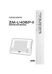
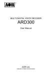
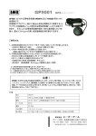
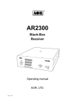
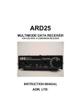
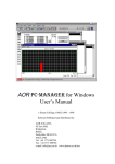
American Communication Systems
Discover the Power of Communications ™
TO ORDER – VISIT http://www.ameradio.com
®
ETHERNET CONTROLLER
ARL2300
User Manual
AOR Ltd.
Authority On Radio Communications
Introduction
Thank you for purchasing ARL2300.
The ARL2300 Ethernet Controller is an option for the AR2300 and AR5001D communication
receivers, which allows remote control and remote listening through the network.
The client software is based on the Java 2 platform and requires version 1.6 (Java SE 6 runtime)
or higher to be installed on the PC on which it is running.
The settings of ARL2300 can be easily changed through the local network (DHCP mode) by
using a browser, based on Apple’s “Zero configuration” software Bonjour.
To obtain the best possible results from your ARL2300, we strongly recommend that you read
this manual and familiarize yourself with ARL2300.
As for any network related remote control device, a good understanding of LAN,WAN,
routers, IP addresses, port forwarding, etc... is necessary to set-up and use ARL2300.
Very importantly, you must be able to set-up port forwarding on your own router! Make
sure you have access to your router manual before going ahead in setting up ARL2300. As
there are hundreds of different router models on the market, with almost as many
different ways to configure them, AOR is unable to assist you in troubleshooting port
forwarding and network security issues.
Every effort has been made to make this manual correct and up to date. Due to continuous
developments of the device, we acknowledge that there may be some errors or omission
anomalies.
1
Table of contents
Introduction ........................................................................................................................................... 1
1
Included in this package................................................................................................................. 3
2
Externals ....................................................................................................................................... 4
3
Typical client / server network ........................................................................................................ 6
4
Connection to AR2300/AR5001D receiver ...................................................................................... 7
5
Front panel power state ................................................................................................................. 9
6
ARL2300 settings ........................................................................................................................ 10
7
ARL2300 client software .............................................................................................................. 18
7.1
How to use the client software.............................................................................................. 18
7.2
Control screen ................................................................................................................... 189
7.3
Terminal command window.................................................................................................. 20
8
Communication procedure ........................................................................................................... 21
8.1
ARL2300 communication protocol ........................................................................................ 21
8.2
TCP receiver control port ..................................................................................................... 21
8.2.1
Special command prefixes ................................................................................................... 22
8.2.2
Firmware version ................................................................................................................. 23
8.3
UDP audio transmission port ................................................................................................ 23
9
Serial port communication specifications ...................................................................................... 25
10
Factory default settings ................................................................................................................ 26
11
ARL2300 specifications................................................................................................................ 27
2
1
Included in this package
ARL2300 device
1
Control cable
1
Length 0.9m, straight D-sub 9pin
Audio cable
1
Length 1m、φ3.5mm stereo
Rubber feet
1
Set of four
Printed manual
1
CD-ROM
1
Client software & manual pdf.
What you need to prepare:
-One straight LAN cable for connection between ARL2300 and your router.(Not supplied)
-One available LAN port on your router
Note: When used with the AR2300/AR5001D receivers, ARL2300 is receiving power directly
from the receiver through the control cable. It does therefore not need to be powered
by an AC adapter.
Printed manual
ARL2300
CD
Control cable
Rubber feet
Audio cable
3
2
Externals
ARL2300 front view
ARL2300 on top of AR2300 receiver
4
Front panel
STA-L
Red LED, log-in state
STA-A
Green LED, operation state
Audio IN
Audio input 3.5φstereo jack
AUX
Serial port for future applications
Back panel
LAN
LAN port
Receiver
Serial connection to receiver
DC5V IN
DC 5V External power input. (Not
needed if connected to
AR2300/AR5001D receivers)
5
3
Typical client / server network
Case 1: Through a router with NAT.
Connect to the external IP
address of your router.
Setup port forwarding in
your router.
Router’s external IP.
Port forwarding
Router with NAT
(Network Address Translation)
Client software on PC
You need to have a GLOBAL IP address assigned to the external port of your router.
(Please inquire your internet provider to this effect) Dynamically addressed IP
addresses do often change by nature, therefore the client side would have no way to
track the IP address changes and would not be able to connect to the remote receiver.
It is necessary to setup PORT FORWARDING in your router, towards the IP address of
your ARL2300. See chapter 6 “ARL2300 settings” regarding the related port numbers
and IP address. Please refer to your router’s manual on how to setup port forwarding.
Case 2: Through the Intranet (router without NAT)
Connect to IP address of
ARL2300.
IP address of ARL2300
Router without NAT
Client software on PC
When you connect to your ARL2300 over the network from the client side software, you
must first input the IP address of ARL2300 (or external IP address of your NAT router
when using NAT) as a target. You can also input a hostname which shows the IP address
registered in the DNS.
6
4
Connection to AR2300/AR5001D receiver
■Receiver serial communication settings
If you have changed the receiver’s serial communication settings from the default values, make
sure to revert to following:
Communication speed
115200bps
Interface
USB priority, or AUX priority, or AUX only
Flow control
none
■Setting the receiver’s DIP switches
After switching the receiver OFF, use a “minus” driver to put the S2 #2
dip switch into position ON, as described in this graphic >>
Warning: Changing dip switch settings while the receiver is ON
will cause a receiver malfunction!
AR2300: The power switch is on the front panel
AR5001D: Use the main power switch on the BACK of the receiver.
Dip switch access for AR2300 (bottom of receiver)
7
S1
S2
S3
■Cable connection
The receiver being switched off, connect the cables as follows:
ARL2300 front panel
ARL2300 rear panel
To your ROUTER or HUB
LAN cable
(not supplied)
Control cable
Audio cable
Receiver rear panel
Warning: Connecting / disconnecting the control cable while the receiver is ON will
cause a receiver malfunction!
Backside of ARL2300 & AR2300 with all cables connected
Remarks: On the receiver side, the audio cable can alternatively be connected to the back panel’s
LINE output as well as the front panel’s PHONES output. Nevertheless, audio level adjustment is
not possible when connected to LINE
8
5
Front panel power state
Once all cables are connected as explained in chapter 4 “Connection to AR2300/AR5001D
receiver”, you can switch on the receiver. Switching on the receiver will at the same time power
the ARL2300.
Right after power is on, the red STA-L led will be lit. After approx. 1 minute, ARL 2300 will enter
in stand-by mode, the red STA-L led will go off and the green STA-A will be lit. The time necessary
to enter the stand-by mode might vary depending on the network environment.
■ARL2300 LED status indicator
ARL2300 status
STA-L(red LED)
STA-A(green LED)
Power is off
off
off
Right after powering on, initialize time
on
off
Initializing has ended, stand-by mode
off
on
Connected to client, but no transmission to client
on
on
Connected to client, with transmission to client
on
flashing
Firmware download & installation
Combination of both ON and both flashing
9
6
ARL2300 settings
Hardware & software requirements to change the ARL2300 settings:
Any Windows or Mac PC with a browser having the “Bonjour” add-on installed. See details
below.
The ARL2300 settings are accessible with a browser using ZEROCONF, a service discovery
protocol based on Apple Inc.’s BONJOUR software. The IP address and host name (*1) are
assigned automatically, providing your computer has Apple’s BONJOUR (*2) installed, and that
your PC is connected to the same LAN than ARL2300.
*1:
Host name assigned automatically by BONJOUR service discovery.
Displayed host name example:
http on arlan-0
When more than one ARL2300 devices are connected to the same LAN, the host names are
displayed as follows: http on arlan-1, http on arlan-2, http on arlan-3, etc…
*2:
BONJOUR add-on per browser
Safari
Bonjour installed by default
Mozilla Firefox4
DNSSD for Firefox add-on needed
Mozilla Firefox3
BONJOURFOXY add-on needed
Microsoft Internet Explorer
BONJOUR FOR WINDOWS software needed
(Installers on Windows systems normally place Bonjour files in a folder called “Bonjour” within
the “Program Files” folder.)
ARL2300 has its IP address automatically assigned by the DHCP server; nevertheless you need
to manually input the IP address (host name) in the client software.
Although the ARL2300 settings page can be accessed at any time, network configuration
changes can only be done when ARL2300 is in stand-by mode (only the green LED is on)
To open the settings page of ARL2300, type the following address in the browser bar:
http://arlan-0.local:48753/
You will then be asked to enter the user name and password (neither can be changed).
User name:
Admin
Password:
Arl_2300
After a successful login, the following settings page will appear:
10
■Address settings:
By default, “Obtain an IP address automatically” is selected, nevertheless you can choose to
manually enter address parameters to match a particular network environment.
・IP Address(required)
IP address you wish to allocate to ARL2300
・Netmask(required)
Netmask for ARL2300 according to the specific network environment
11
・Gateway
Gateway for ARL2300 according to the specific network environment. Leaving it empty is as
if you entered the values 0.0.0.0
・NameServer
NameServer for ARL2300 according to the specific network environment.
(Required for firmware update)
■Port settings
You need to open the following ports on your (NAT) router and to forward these ports to the
ARL2300. Receiver remote control will not function unless port forwarding is correctly initiated.
Please consult your router documentation on the procedure.
Each port number can be set to any value between 10001 and 65535.
・TCP Port
Port used to send the control commands to the receiver
・UDP Port
Port used for audio from the receiver
・Conf Port
Port used to access the ARL2300 settings through the browser
■Timeout
Set the range from 10 to 60 seconds, in 5 seconds steps.
If the command data from the client software is not received within the time set here,
ARL2300will cut the communication with the client.
12
■Authentication
Here you can restrict access from the client software by setting a username and password of
your choice..
Leaving blanks would allow anyone to access ARL2300.
■Save options
Reload(without SAVE)
Reverts all settings to the last saved state.
Quit(without SAVE, LOGOUT)
Quit the settings page without saving any changes you
might have made.
Save
Settings are saved.
At this stage, the changes have not been implemented by ARL2300 yet, as it
needs to be rebooted.
The next chapter explains this procedure.
13
■Summary of saved settings & reboot
Once your changes have been saved as
per the previous chapter, the summary of
your ARL2300 configuration will be
displayed and you will be given the following
choices:
Reboot
ARL2300 will be rebooted and the
changes implemented.
Quit without Reboot
Logout from the ARL2300 settings
without rebooting ARL2300. The settings
changes you have previously saved are
not implemented yet by ARL2300.
Return to Config
In case you need to edit the settings
again.
14
■Current client connections
Here will be displayed the IP address of the currently connected client.
Force disconnect
Click this button to
force disconnection of
the currently connected
client.
This is the display when no client is connected to ARL2300.
Update information
Click to refresh the
current client
connection status (*).
(*) While you access the settings page, the “current connection status” is not automatically
refreshed. In other words, you would not know if a client accesses ARL2300 while you are on the
settings page, unless you click the “Update information” button.
■Firmware update
The ARL2300 firmware can be updated online, using ports TCP 80 (HTTP) and 443 (HTTPS).
Make sure that your router does allow ARL2300 to access these ports; otherwise the firmware
update will fail. Please consult your router documentation on the port access procedure.
Please note that the online update might be impossible depending on your firewall and proxy
settings.
To proceed with the update, click on the “Move to ARL2300 firmware update page” link at the
bottom of the ARL2300 settings page.
Possibility #1: ARL2300 already has the latest firmware, in which case the following message
appears:
In this case just click on “Exit ARL2300 Firmware Update” to return to the settings page.
15
Possibility #2: There is a newer firmware version available, in which case the following page
appears:
Once you are aware of the risks involved and if you wish to go ahead with the update, click on
YES
The screen will inform you on the update progress as follows:
Downloading the kernel…
Installing the kernel…
16
Downloading userland image…
Installing userland image…
End of firmware upgrade,
(ARL2300 is automatically rebooting. Disregard any message saying that the Internet connection
was interrupted.)
17
7
ARL2300 client software
Hardware & software requirements to run the client software:
Any PC running Java 2 (v.1.6 or later). See details below.
The client software is based on the Java 2 platform and requires version 1.6 (Java SE 6 runtime)
or higher to be installed on the PC on which it is running. For more information please refer to
http://java.com
The supplied ARL2300 client software only supports basic functions of VFO reception, over the
network and the internet. The current version does not support the receiver’s advanced features
such as search, scan, simultaneous reception etc...
7.1
How to use the client software
◆ Do not execute the client software directly from the CD. You first need to copy the
software folder to your client PC.
◆ ARL2300 only allows one client connection at a time. If
somebody else is already connected when you try to
establish the communication, you will encounter this
“Busy!” error message.
◆ Cannot connect to host (ARL2300) message
Possible reasons for this error message are:
The IP address (or host name) for ARL2300 or its TCP
port number you entered in the client software, are
incorrect.
The IP address, when using dynamic DNS on ARL2300, has not been updates
If you can connect to ARL2300 but hear no sound, then most probably the UDP port number
is incorrect.
◆ Login incorrect
The user name and/or password you entered are
incorrect.
Entries are case sensitive.
18
7.2
Control screen (see separate A4 size print)
19
7.3
Terminal command window
Checking the “Terminal” box at the bottom right of the client software control screen does open
the terminal command window.
Refer to the AR2300AR5001D receiver manual for
the complete command list. To send a command to
the remote receiver, type the command in this
terminal window and hit the
Exec
button.
Please note that here you can only SEND
commands but this window will not show you the
response sent by the receiver! This being a “client
software” interface, the software will interpret the
responses in its interface.
Note: As an alternative to the AOR software, you
can use a Telnet software to test commands and their responses
Example of Telnet command testing
20
8
8.1
Communication procedure
ARL2300 communication protocol
TCP is used for control data communication between ARL2300 and the client software (client
PC).
8.2
TCP receiver control port
The receiver control and the ARL2300 control are done with the following TCP control port.
TCP communication chart (command names omitted)
If the TCP connection procedure has been successful, ARL2300 is sending a “230 Welcome”
message to the client PC. Starting from that moment, the receiver is under remote control.
If you are using a terminal software, you can now try to send commands such as RX, RF, etc…
The command should be terminated by <CR> or <CR><LF>. All responses from receiver are
terminating by <CR><LF>.
Three digits of result code are added to each message from the ARL2300. If the blank character
(blank code) has been added immediately after the result code, the ARL2300 send a simple
message and wait for the data from client.
21
If the hyphen (-) has been added immediately after the result code, there is a data or message
that needs to be send to client.
Do not attempt to send data to the ARL-2300 until the appropriate result code (result code with
immediate blank code) is received. Make sure to send data to ARL2300 after the result code with
immediate blank code.
The result code consists of three digits (in hundreds) and represents the following message
groups:
2xx
-
Immediate success on received command and message.
3xx
-
Requesting more commands.
4xx
-
Send message to client and disconnect the link.
5xx
-
Error
The 2xx result code generated from the ARL2300 in the TCP Communication Chart has following
meanings:
231
-
Prefix for special command,
232
-
Adding time stamp to the UDP packet is possible.
233
-
Adding LM value (Receiver S-meter value) to the UDP packet is possible.
234
-
Maximum octets value for the audio data for one packet.
235
-
ARL2300 version information.
New result codes may be added at the time of future firmware updates, however, successful TCP
connection establishment always ends with the “230 Welcome” message. Refer to chapter 8.3
(UDP audio transmission port) for details on result codes 232, 233 and 234.
8.2.1 Special command prefixes
The special CPF (Special Command Prefix) is a header character that controls ARL2300. If data is
sent to the ARL2300 without special CPF, the data is applied to the receiver directly. No data is
passed on to the receiver if ARL2300 received the command with special CPF, and the data is used
to control the unit.
Command
Command Type
Description
Audio data length
Set the length of audio data for one UDP packet. The length
of UDP packet
should be set by octet. The octet value should be smaller than
Prefix
b
the result code of 234 and it should be an even number.
Example: b2048 ---- Set to octet 2048
e
Set special CPF
The default character is “@”. To change the special CPF, use
this command.
Example: e+
22
----
Set special CPF to “+”
f
Select LPF
Selects the LPF in the ARL2300. The cut-off frequency and
parameter as follows:
f0: Through, f1: 9kHz, f2: 6.4kHz, f3: 3.2kHz
g
Select gain
Selects the audio gain of the ARL2300. The audio gain and
parameter as follows:
g0: 0dB, g1: +3dB, g2: +6dB, g3: -6dB
l
p
q
Add LM to UDP
Adds the LM value (S meter value) to UDP data.
packet
Example: l0: No LM vale is added , l1: LM value is added
Start audio
This command is required to start audio transmission from the
transmission
ARL2300. Please see details in chapter 8.3.
End audio
Stop audio transmission from the ARL2300.
transmission
s
Select audio
Selects the sampling rate (audio quality). This command
sampling rate
should be used with the “f” command. Available sampling
rates and parameters as follows:
s8000: 8kHz, s11025: 11.025kHz, s16000: 16kHz,
s22050: 22.05kHz, s32000: 32kHz, s44100: 44.1kHz,
s48000: 48kHz
t
Add TIME STAMP
Adds the time-stamp to UDP packet. The time-stamp format
to UDP packet
is a value in seconds started from Jan 1, 1970. (aka Unix time)
Example: t0: No time stamp is added. t1: Time stamp is
added.
8.2.2 Firmware version
The number followed by the result code 235 is a version number of the ARL2300. The number
only represents major change in the firmware.
8.3
UDP audio transmission port
To receive UDP data (audio data) from remote ARL2300, the client PC needs to send the “p”
command as described in chapter 7.2.1.
UDP Payload Diagram
23
Furthermore, UDP requires audio transmission start command immediately after the “p”
command.
The UDP command is @p1. This command should be sent to the ARL2300 every 10 to 120
seconds until audio transmission is stopped. To temporarily stop the UDP data transmission from
the ARL2300, the q1 command should be issued. To stop the UDP data transmission completely,
the q command should be issued. The q1 command can be altered by q if complete termination
of UDP transmission is needed.
■ AUDIO DATA
Audio data is an uncompressed PCM with symbol consisting of 16-bit little-endian format. One
payload can carry 800 octets as initial value. The size can be changed by “b” command as
described in chapter 8.2.1 “Special command prefixes”. However, maximum octet value should
be smaller than the result code of 234 and it should be an even number.
The maxim audio data size shown in the TCP Communication Chart is 2048, that is a part of result
code 234 (234-AUBFSZIE2048) shown in the example.
■ SEQUENCE NUMBER
Every single octet data send over UDP has a sequence number between 0 and 255. The sequence
number increases in every UDP packet transmission.
■ TIME-STAMP
The time-stamp format is a value in seconds started from Jan 1, 1970. (aka UNIX time) and it
represents the latest incidence of the generated data. The time-stamp is 4 octets in size and
stored in big-endian format. The inclusion of TIME-STAMP can be selected by the “ t“ command as
described in chapter 8.2.1 “Special command prefixes”. The default value is t0 (No TIME-STAMP
is added).
■ LM VALUE
The LM value space of the UDP payload stores the leading 9 characters string of the actual LM
value. If the associated receiver responds with the LM command, the receiver sends the LM value.
The inclusion of LM can be selected by the “ l “ command as described in chapter 8.2.1 “Special
command prefixes”. The default value is l0 (No LM value is added).
24
9
Serial port communication specifications
1. Receiver (back panel)
Communication speed
115200bps (non-changeable)
Data
8bit
Stop bit
1
Flow control
none
Pin layout
DTE
2. AUX (front panel) (for future applications)
Communication speed
9600bps (non-changeable)
Data
8bit
Stop bit
1
Flow control
none
Pin layout
DTE
25
10 Factory default settings
■ARL2300 defaults
Item
Default
Remarks
TCP Port
48752
Used for receiver control
UDP Port
48752
Used for voice transmission
Conf Port(TCP)
48753
Used to access the configuration screen
User
arl2300x
Login name to access ARL2300
Password
Arl_2300Q
Password to access ARL2300
Configuration User
Admin
Configuration Password
Arl_2300
AUX (for future applications)
48751
Login name to access configuration. Cannot be
changed.
Password to access configuration. Cannot be
changed.
Number set automatically as TCP number -1.
Cannot be changed manually.
26
11 ARL2300 specifications
Item number
ARL2300
Function
Ethernet controller for AR2300/AR5001D receivers
LAN socket
Receiver socket
Audio IN socket
RJ-45 type
10BASE-T / 100BASE-TX10/100Mbps (auto-sense)
D-sub 9pin type
Connection to AR2300/AR5001D receiver
3.5mm stereo used as mono
Connection to AR2300/AR5001D audio output
AUX socket
D-sub 9pin type, RS-232C (For future applications)
Network protocols
TCP (receiver control), UDP (voice transmission)
Required network speed
Constant 80, 160, 500kbps depending on sampling rate
choice.
Controller
Cirrus Logic EP9307 CPU core ARM920T (200MHz)
Operating system
Linux (Kernel 2.6.x)
Power requirements
DC5V by external power source. When connected to
AR2300/AR5001D receiver, power is supplied by receiver.
Power consumption
1.8W (typical)
Current consumption
Max. 300mA
Operating temperature
0 〜 50 °C
Dimensions
(H)35mm x (W)130mm x (D)150mm (projections excluded)
Weight
400g (without cables)
Control cable(D-sub 9pin, straight) x1
Supplied accessories
Audio cable(φ3.5mm stereo) x1
Rubber feet x4
Hardware & software
requirements for
Any Windows or Mac PC with a browser having Apple’s “Bonjour”
add-on installed.
ARL2300 settings
Hardware & software
requirements for client
Any PC running Java 2 (v.1.6 or later).
27
®
AOR Ltd.
2-6-4 Misuji, Taito-ku, 111-0055 Tokyo,
Authority On Radio Communications
Japan
www.aorja.com
(v01 20110803)