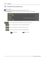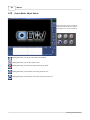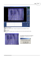
1
Help Manual
© 2007 Digital Video Witness
Digital Video Witness
The Digital Video Recorder Software
by Digital Video Witness
Digital Video Witness (DVW) is Say Security's trademarked
line of surveillance products including Cameras, Pan Tilt
Zoom Speed Domes, Professional DVR’s, Network DVR’s
and Mobile DVR’s. DVW is the perfect fit for every
surveillance need from Convenience Stores with Integrated
Point of Sale, School and University Campuses, or high end
Government applications.
Manual
© 2007 Digital Video Witness
All rights reserved. No parts of this work may be reproduced in any form or by any means - graphic, electronic, or
mechanical, including photocopying, recording, taping, or information storage and retrieval systems - without the
written permission of the publisher.
Products that are referred to in this document may be either trademarks and/or registered trademarks of the
respective owners. The publisher and the author make no claim to these trademarks.
While every precaution has been taken in the preparation of this document, the publisher and the author assume no
responsibility for errors or omissions, or for damages resulting from the use of information contained in this document
or from the use of programs and source code that may accompany it. In no event shall the publisher and the author be
liable for any loss of profit or any other commercial damage caused or alleged to have been caused directly or
indirectly by this document.
Printed: May 2007 in (Ada, OH)
4
Manual
Table of Contents
Foreword
0
7
Part I Main
1 Attention
................................................................................................................................... 8
2 Installation ................................................................................................................................... 9
Installation Procedure
..........................................................................................................................................................
Rear View
..........................................................................................................................................................
Connecting Pan/Tilt
..........................................................................................................................................................
Drive
Connecting PSTN,
..........................................................................................................................................................
ISDN, or Leased Circuit
External Sensors
..........................................................................................................................................................
External Control
..........................................................................................................................................................
Connection
3 Setup
9
10
11
12
13
14
................................................................................................................................... 15
Log In Screen..........................................................................................................................................................
Main Screen ..........................................................................................................................................................
Hardware Setup
..........................................................................................................................................................
(cameras)
Hardware Setup
..........................................................................................................................................................
(sensors)
Hardware Setup
..........................................................................................................................................................
(controls)
Hardware Setup
..........................................................................................................................................................
(External Monitor)
Motion Detection
..........................................................................................................................................................
Recording/Display
..........................................................................................................................................................
Schedule Setup
..........................................................................................................................................................
Schedule Setup
..........................................................................................................................................................
Holiday
Screen Division
..........................................................................................................................................................
Network Setup
..........................................................................................................................................................
Site Information
..........................................................................................................................................................
View Log
..........................................................................................................................................................
User Management
..........................................................................................................................................................
Audio Setup ..........................................................................................................................................................
System Setup..........................................................................................................................................................
Backup Settings/Calendar
..........................................................................................................................................................
Setup
Adding a Backup
..........................................................................................................................................................
Schedule
Easy Update ..........................................................................................................................................................
Email Transmission
..........................................................................................................................................................
Motion Tracking
..........................................................................................................................................................
Storage Setup..........................................................................................................................................................
EMap
..........................................................................................................................................................
15
16
18
19
20
21
22
26
27
29
30
31
34
38
39
41
42
45
46
47
48
49
52
53
4 Operation ................................................................................................................................... 56
Pan Tilt Controls
..........................................................................................................................................................
for P/T/Z Cameras
Pan Tilt Controls
..........................................................................................................................................................
Live Audio ..........................................................................................................................................................
Entering into ..........................................................................................................................................................
Search Mode
Search Mode ..........................................................................................................................................................
Still Image Tools
Search Mode:..........................................................................................................................................................
Seach Tools
Search Mode:..........................................................................................................................................................
Playback Controls
Search Mode ..........................................................................................................................................................
Search Mode ..........................................................................................................................................................
Skip/Delay
Search Mode:..........................................................................................................................................................
Search Option Pannel
Search Mode:..........................................................................................................................................................
Index Search
56
58
59
60
61
62
63
64
65
66
67
© 2007 Digital Video Witness
Contents
5
Search Mode:..........................................................................................................................................................
Object Search
Search Mode:..........................................................................................................................................................
Audio Playback
Backup
..........................................................................................................................................................
JPEG Backup..........................................................................................................................................................
Search Mode/Backup
..........................................................................................................................................................
Select Media
Watermark Check
..........................................................................................................................................................
Time Backup ..........................................................................................................................................................
AVI Backup ..........................................................................................................................................................
Email Backup..........................................................................................................................................................
QuickBurn ..........................................................................................................................................................
Common Backup
..........................................................................................................................................................
Options
Index
68
72
73
74
75
76
77
79
81
82
83
0
© 2007 Digital Video Witness
5
Part
I
Main
Manual for Installer and User
Ø
Ø
Ø
Ø
Ø
Ø
Ø
Ø
Ø
Ø
Ø
DN-1808S
DN-4408S/45086
DN-44208S/45208S
DN-1816
DN-4416/4516
DN-44216/45216
DN-3416/3516
DN-34216/35216
DN-58216
DN-6816
DN-68232
© 2007 Digital Video Witness
7
8
1
Manual
Attention
When the DVR starts up, you are automatically logged on as Administrator in the Windows operating system. This enables
you to access all necessary network and connection protocols to configure the DVR without restrictions.
> DO NOT open the DVR case and add/remove hardware.
> DO NOT add users to the Windows operating system. (The DVR will no longer reboot unattended.)
> DO NOT install any other software on the DVR.
> DO NOT customize the Windows operating system in any way. (Setting screen savers, changing the desktop, adjusting
power settings, etc.)
> DO NOT use the DVR to browse the Internet or read e-mail.
(Computer virus attacks are not covered under warranty.)
Any of these changes will interfere with the
operation of the DVR and will
VOID YOUR WARRANTY!!!
Safety Precautions
When selecting a place for the DVR, avoid locations with:
·
Excessive heat, such as direct rays of light or heating appliances.
·
Excessive moisture, dust, or smoke.
·
Magnetic substances or electric wave equipment in close proximity.
·
Excessive hot or cold temperature (operating temperature from 5 to 45 degrees C)
·
Unstable or elevated surface.
Before proceeding further with this manual, make sure to follow the precautions below:
· Plug the power cable in after connecting all
devices. Connecting a device when the power is
on may cause problems. Do not forget that the
DVR is automatically booted when the power
cable is plugged in.
· Leave enough space around the DVR to avoid tangling cable lines and blocking ventilation.
· Keep the DVR clean of dust and foreign objects.
· In case of malfunction, do not try to repair the DVR by yourself. Contact your local distributor for assistance.
© 2007 Digital Video Witness
Main
2
Installation
2.1
Installation Procedure
9
Follow the steps below to install the DVR:
·
Place the DVR to the proper place following safety precautions on page x.
·
Connect cameras to the DVR(see Connecting Pan/Tilt Drive if Pan/Tilt cameras are used)
·
Connect the DVR to the communication network.
·
Connect external sensors and controls
·
Plug in the watchdog cable
IMPORTANT: An unconnected watchdog cable is a common mistake when installing the DVR
and causes rebooting every 10 minutes that may damage the hard disk in the DVR
·
Plug in the power cable
© 2007 Digital Video Witness
10
2.2
Manual
Rear View
© 2007 Digital Video Witness
Main
2.3
Connecting Pan/Tilt Drive
© 2007 Digital Video Witness
11
12
2.4
Manual
Connecting PSTN, ISDN, or Leased Circuit
© 2007 Digital Video Witness
Main
2.5
External Sensors
© 2007 Digital Video Witness
13
14
2.6
Manual
External Control Connection
© 2007 Digital Video Witness
Main
3
Setup
3.1
Log In Screen
15
Starting Up
This is the screen that will appear when DVW is
first loaded.
Left click to bring up the following login screen
*Users settings can be changed from the user management tab in the setup window.
© 2007 Digital Video Witness
16
3.2
Manual
Main Screen
Main View Screen
This is where the live images from your cameras
will appear.
Left click on any image to bring it to full screen
view. Left click on the image again to return to
normal view.
Clock
Setup and Search Modes
Indicates current date and time
Left click to enter Setup (Camera selection, Screen
division, Schedule, Audio, Motion, etc.) or Search
Mode. (Review and backup recorded data)
Mode Indicator
Mode indicator will indicate whether you are in
Display, Search, or Pan/Tilt.
Display, Search, or Pan /Tilt mode.
Full Screen View
This button will set the main screen to “Camera only”
view. The GUI (Graphic User Interface) which
includes the Screen Division buttons, the Event
Indicators, the Clock, Setup and Search buttons,
Power button, etc. will be hidden.
Right click on the screen to return to normal view.
Right click to return.
Loop
Storage Indicator
Top line shows total Hard Drive space allocated and
available for data storage.
Numbers in the blue box show Hard Drive space that
has been used for data storage in Megabytes and
Percentage of free space remaining. When
percentage of free space reaches 0%, the DVR has
used all available storage and will begin to overwrite
(replace) the oldest recorded data.
(It is normal for the ‘Free Space’ indicator to read ‘
0% Free’ once the DVR has started overwriting the
oldest data. This number will not change unless you
reallocate (erase) the storage drive.)
Sets main view to 4 camera split and rotates view
continuously through all active cameras starting with
1~4, then 5~8, then 9~12, then 13~16, then back to
1~4, etc.
Click on an image, or select a Screen division button
to stop rotation and return to normal mode.
© 2007 Digital Video Witness
Main
17
Power Button
Screen Division Selections
Left click on the power button in Display
mode to turn off the DVR.
Unit will stop recording and turn itself off.
Use the Power switch (on the front of the
DVR) to restart the unit.
Select the number of cameras you wish to view on the main screen.
Choose 4, 6, 9, 10, 13, or 16 camera splits
The cameras that will appear in each view are assignable in setup
under “Screen Division”
Left click on any image to bring it to full screen view. Left click on
image again to bring it to normal view.
Camera, Sensor, and Control
-Relay Event Indicators
Each numbered button corresponds to the
similarly numbered device in each category.
Camera indicators will flash when a camera
detects motion. Sensor indicators will flash
when a device (Glass break or motion
detector) is tripped.
Control indicators will flash when a relay
(Alarm, siren, strobe, etc.) has been
activated. Control relays may also be
manually activated by left clicking on the
indicator. Click on it again to deactivate.
© 2007 Digital Video Witness
Logout Button
This button logs out the current user.
18
3.3
Manual
Hardware Setup (cameras)
Hardware setup allows
users to modify external
devices configurations,
such as cameras, sensors,
and controls.
[Setup]
Check the box to use the camera.
[Name]
Type in the camera names. Up to 14 characters
are allowed.
[Sensor]
You can connect sensors to available cameras.
This functions enables cameras to record
automatically when the connected sensor (s) is
triggered.
To connect a sensor to a camera, type the number
of the sensor in appropriate camera number. If
you wish to connect to multiple sensors to a
camera, type sensor numbers in the box,
separating them by comma.
Example, in order for Camera 3 to start recording
when Sensor 1 or Sensor 3 is triggered, type “1, 3
” in [sensor] box against Camera 4.
[P/T]
Check the box if the camera is on PAN/Tilt type.
[Type]
Use the scroll bar to select PAN/TILT camera
model from the list. This option box is disabled
if [P/T] box is not selected.
[Motion]
You can link cameras to other available
cameras. This function enables linked
cameras to record automatically when the
main camera detects movement.
To link a camera to another camera, type
the number of the camera you wish to
connect in appropriate camera number. If
you wish to connect multiple cameras to a
camera, type camera numbers in the box,
separating them by comma.
Example: In order for Camera 5 to start
recording when Camera 1 or Camera 2
detects motion, type 1,2
in [Motion] box
against Camera 5
[Emergency]
Select a preset location where the Pan/Tilt
camera will return to when any linked
sensor is triggered.
© 2007 Digital Video Witness
Main
3.4
Hardware Setup (sensors)
[Setup]
[Use alarm]
Check the box to enable sensors. Uncheck the
box to disable sensors. Sensor inputs are
standard on Rack Mount units and optional on
Desktop units. If your unit does not have
sensor inputs then do not use this function.
Selecting [Use alarm] will enable the built
in internal speaker to beep if a sensor is
triggered. The speaker however will not
beep if the corresponding camera schedule
is set to Continuous Recording.
[NC/NO]
[Recording Time]
Choose a sensor type. Click the button
to switch between [NC] and [NO]
sensor types.
· NC = Normally Close type. If the
door/object with the sensor installed
is not closed, the sensor will trigger.
· NO = Normally Open type. If the
door object with the sensor installed
is not open the sensor will trigger.
Select the number of seconds to record
when a sensor is triggered. This function
will not work if the recording schedule is
not set to Sensor or Motion
[Camera Preset]
Enter the desired camera in the text field. Set
the preset for the camera to allow the specified
camera to Pan/Tilt/Zoom to a location when a
sensor has been triggered.
© 2007 Digital Video Witness
19
20
3.5
Manual
Hardware Setup (controls)
[Sensor]
[Setup]
Check the box to use the controls.
[Name]
Type in control names. Up to 14 characters are
allowed.
[Auto On/Off]
Auto function automatically activates controls
during selected time. To enable Auto function
choose the time from scroll list. Default is set
from 00:00 to 24:00.
To connect a sensor to a control, type
the number of the sensor on the
appropriate control number.
If you wish to connect multiple sensors to
a control, type the sensor numbers in the
box, separating them by commas.
Example: In order to tun on Control 3
when Sensor 1 or Sensor 2 triggers, type
"1,2" in the box against Control 3.
[Working sec]
Assign how long the control will stay
active once it is triggered. Maximum is
255 seconds and default is 0 seconds
© 2007 Digital Video Witness
Main
3.6
Hardware Setup (External Monitor)
[Setup time (sec)]
Select time for displaying a channel on the external monitor.
[Tip]
Images from external monitor output use Split Screening Method instead
of Consecutive
Conversion Method when using models DN 3416 and DN 34216. It
might not indicate set item for external monitor.
In case of DN6816 and DN68232, the screen on the external monitor is
the same as seen on the DVR.
The external monitor out is not available with DN34XX, DN35XX and
DN68XX.
[Camera]
Select the channel you wish to display on the external monitor.
© 2007 Digital Video Witness
21
22
3.7
Manual
Motion Detection
[Camera]
[Alarm]
Select the camera you wish to setup. The
description below is related to the camera
you selected here
.
If the box is checked, the internal speaker will
beep when the camera detects motion.
[Detection Area]
To enable cameras to record automatically
by motion detection, you must select the
detection areas. To select detection area,
place the mouse cursor over the channel
screen and drag the cursor in any direction
you wish. You can assign up to 5 separate
areas for each camera.
The speaker however will not beep if the
camera is set to Continuous Recording mode
in Scheduled Setup (see page page 27). The
speaker's activation time can be set by the
scroll lists.
[Control]
When the camera detects motion, the
connected control will activate for the
designated time.
[Sensitivity]
Change sensitivity of motion detection.
Default value is set to 15 and it is the
recommended value.
© 2007 Digital Video Witness
Main
[Object Watch]
To use the Object Watch function, select the camera number and check the [Object Watch] box in
surveillance mode, if motion is detected within the Object Watch setup area, the cell color of the
Object Watch will change.
© 2007 Digital Video Witness
23
24
Manual
© 2007 Digital Video Witness
Main
25
[Area Clear]
Delete Detection Area for selected camera. To manually delete an area, simply drag the detection area
outside the channel screen.
[Area Draw]
Assign an entire channel view as a detection area.
[Camera Adjustment]
Adjust brightness, hue and contrast for each camera. Caution: Adjusting these options will affect the
recorded data.
[Color]
If the camera is black and white, click [Color] to change the channel into Black and White. The default is
set to Color for all channels.
[Default]
Set values in (10) and (11) back to default.
[Set quad rotation time]
Select the rotation time for Channel Rotation.
[Full screen when motion]
The channels of the cameras specified in this box will change to full screen if they detect motion. If you
wish to select multiple cameras, type the camera numbers in the box, separating them by a comma.
[Full Screen when sensor]
The channels of the cameras specified in this box will change to full screen if a sensor is activated. If you
wish to select multiple cameras, type the camera numbers in the box, separating them by a comma.
[Delay Time (sec)]
Delay Time works in conjunction with [Full screen when motion], and will freeze the channel if motion
is detected on cameras with [Full screen when motion] enabled. To enable Delay Time, select the
number of seconds from the scroll list.
[No full screen]
Cancels options set on [Full screen when motion] and [Delay time].
[Color of motion area]
When a camera detects motion its channel will highlight the Detection Areas by the color you select
here (Red or Green).
© 2007 Digital Video Witness
26
3.8
Manual
Recording/Display
[Camera]
[Rec. Quality]
Display camera numbers.
[Emergency Recording]
You can change the quality of the
recording for each camera. The higher
recording quality the more storage space is
needed.
Example: In order to turn on Control 3
when Sensor 1 or Sensor 2 triggers, type
"1,2" in the box against Control 3.
You can change the recording speed of
each camera in case of emergency.
[Transfer Quality]
[Rec. Frame]
You can change the recording frame rate of
each camera by sliding the scroll bar.
[Sensor]
You can change the image resolution of
each camera.
320x240 or640x480 (384x288 or 768x576
PAL) are recommended.
The DVR may automatically adjust the
frame rate when selecting 640x480
(768x576 PAL).
You can change the quality of the transfer
image for use during transmission. The
higher transfer quality the more bandwidth
is needed.
[Default]
Change all the setting to the default values.
© 2007 Digital Video Witness
Main
3.9
>
·
·
·
·
Schedule Setup
Schedule setup allows you to determine what mode your cameras will operate in at any given time of day.
Continuous: Cameras will record continuously.
Motion:
Cameras will record only when motion is detected.
Sensor:
Cameras will record when triggered by associated sensors.
Prealarm: Cameras will record events up to 5seconds before motion is detected.
Place a checkmark in the box to enable the mode(s)
Removing the checkmark from all four options will set the camera to “Look Only” mode. (No video will be recorded)
You may use more than one mode on each camera.
>
·
·
·
·
·
·
·
·
Supported modes include:
Look Only (No record)
Continuous Record (Disables Motion, Sensor, and Prealarm functions)
Motion
Sensor
Motion + Sensor
Motion + Prealarm
Sensor + Prealarm
Motion + Sensor + Prealarm
© 2007 Digital Video Witness
27
28
Manual
[Camera]
[Record Mode]
Select the camera you wish to setup. All the
descriptions below are related to the selected
camera.
Select Record Mode for selected time interval. If
no mode is selected, the system will not record.
Default isMotion & Sensor Record for 24
hours for all date of the year
[Setting Recording Mode]
The table displays recording mode for every
hour. To change Record Mode, click on the
hour you wish to change (you can drag the
mouse to select multiple boxes. The selected
time will be highlighted in blue. Then
change the mode from Record Mode (4)
setting.
Recording
mode
• C: Continuous Rec.
• M: Motion Rec.
• S: Sensor Rec.
• P: Pre-Alarm Rec.
To be exact to minutes click on the time you
wish to change and a horizontal bar will
appear.
[Simple/Advanced Mode]
In “Simple” mode, all days (Weekdays, Saturdays,
and Sunday/Holidays) are set on a single 24 hour
timeline. Any time adjustments you make will apply
to all days.
In “Advanced” mode, Weekdays, Saturdays, and
Sunday/Holidays each have their own 24 hour
timeline.
Supported Recording
Mode/combinations
• No rec.
• Continuous rec.
• Motion rec.
• Sensor rec.
• Pre Alarm Rec.
• Sensor & Pre Alarm rec
• Motion & Pre Alarm rec
• Motion & Sensor rec
• Motion & Sensor & Pre
Alarm rec.
Motion Recording, Sensor recording, and
- Pre
Alarm Recording cannot be enabled in
conjunction with Continuous recording.
[Set Holiday]
You can set any specific days as holiday.
[Copy To]
To copy the camera's schedule to other
cameras, click Copy To and select the
camera number you wish to copy to.
© 2007 Digital Video Witness
Main
3.10
Schedule Setup Holiday
[Calendar]
[Rotate]
Displays a calendar where you can designate
any date as a holiday.
Displays the list of designated holidays by
time.
•
•
[Add]
<< Move to previous month.
>> Move to next month.
[Rotate]
Click to add selected date(s) as holiday.
[Delete]
To set the selected day(s) as monthly holiday, To delete a designated holiday from the list.
select [Month] from the scroll list. To set as a
yearly holiday, select [Year] from the scroll
list. Leaving the option None will designate
the selected day(s) as holiday for that specific
month and year.
© 2007 Digital Video Witness
29
30
3.11
Manual
Screen Division
[Screen Division]
Screen division assigns which cameras
will be displays on which split screen
mode. Select the split screen mode you
want to setup here.
4CH
6CH
9CH
10CH
13CH
16CH
33CH
36CH
[Tip]
Split screen setup is not available with
DN3416/3516 and DN34216/35216
If a split screen is supported by VIP
(Video Interface Port), VIP mark
appears above the icon.
[Camera Selection]
Enable or disable cameras on the selected
screen division. Disable cameras you do not
want to appear on the Main Screen.
Remember to SAVE your settings before closing!
[Large Screen]
When using 6, 10, 13, or 33 split screen mode,
you can select which camera(s) should be
displayed on the large channel(s). If the
camera has a Video Interface Port, [VIP] mark
is followed by the camera number.
[Default]
Returns settings for the selected screen
division to factory defaults. (All cameras on)
© 2007 Digital Video Witness
Main
3.12
Network Setup
Modem setup tab
contains the settings
for communication of
the DVR.
In the description
below,
“the Site” is referring
to the DVR itself, and
the Center PC is
referring to the PC
connectedto the DVR.
[Type of Connection]
[Max Acceptable]
Click “LAN/PSTN/ISDN/LEASED
CIRCUIT/ROUTER” if you have the DVR
installed on a LAN (Local Area Network) or if
you use the optional 56K modem to provide
remote access to a computer with the “DVR
Center” software installed.
If the DVR is installed on a LAN with a router or
gateway you may have to ‘Port Forward’
the incoming signal from the remote ‘Center’
computer. Some DSL and Cable modems also
require ‘Port Forwarding’. Consult your modem
manual or network administrator for help on ‘
Port Forwarding’.
If your connection requires port forwarding, the
default ports for the DVR are Ports 8080 through
8089. Enable the ports for TCP protocol.
To disable remote connection, check the option
box [No connection].
Set the maximum number of sites that can be
connected to the Center. One Center PC can
connect up to 120 different sites.
[Live Video Stream Bandwidth]
Limit the amount of Data transmitted from the
DVR to remote (Center) computers.
© 2007 Digital Video Witness
[Network Connections]
This buttons brings up the Network Properties
Window and can be used to change your IP
address.
31
32
Manual
[Motion for Emergency Message]
[Emergency phone numbers]
When selected cameras detect motion, an
If you use a modem to connect the DVR to
emergency message will be displayed
the remote, or “Center” computer, then
automatically on Monitor window on DN Center enter the phone numbers of the remote, or
PC, provided Center Software is installed and
“Center” computer(s) that the DVR will
running. To specify the IP address of the PC
send the emergency message to. If the
with Center program installed, eneter the IP
DVR fails to connect to the first number, it
adress on [Emergency IP address].
will dial the second number and attempt to
transmit the message.
[Sensor for Emergency]
[Emergency IP Address ]
Select the sensors that will activate the
Emergency Message function. When a sensor is
If the DVR is connected to a LAN (Local
tripped, the DVR will send a message to the
Area Network) or to the Internet through a
remote, or “Center” computer.
DSL or Cable Modem connection, you can
assign the IP (Internet Protocol) address of
[Transfer Time (sec)]
the remote, or “Center” computer(s) you
Set the time (in seconds) that the modem will
wish to receive the Emergency Message.
keep the connection to the remote computer
open and active. Any image captured by selected
cameras during that time will also be transmitted.
[Use E-Mail Service]
You can send an emergency recording data to your e-mail account.
If you click on [Recipient], a window as below appears
© 2007 Digital Video Witness
Main
· [Mail Server (SMTP)] Enter the address of the outgoing (SMTP) mail server.
· [From] Enter the email account of the sender.
· [Subject] Enter the title of the email.
· [Mail Recipient List] Displays the list of recipients' email accounts.
· [ADD] To add a recipient to the list.
· [DEL] to delete an email account from the list.
© 2007 Digital Video Witness
33
34
3.13
Manual
Site Information
Site information tab
contains system-related
information such as Site
code, Site name, Software
version,… You can also
adjust Surveillance mode
options here.
[Site Information]
This is the Site Code you will need to enter in the Connection setup box on the remote or ‘Center’
computer when you connect to the DVR by modem or LAN.
You may rename the Site Code to any 7 digit alphanumeric name. (7 characters, using letters, numbers, or
combination of each)
If you have more than one DVR you will wish to monitor remotely, you must use a different Site Code for
each.
(Example): DVR # 1= 100-001
DVR # 2= 100-002
DVR #3= 100-003
or DVR # 1=saysc01
DVR # 2= store-2
DVR # 3= dvrmain
[Location/Model/Distributor/Sales Date/Other/Notes]
These are optional information entries.
You may fill in these boxes with information relating to your DVR for easy reference.
These entries will be viewable from the remote or ‘Center’ computer when you connect and enter the setup
mode.
When logging into the Site from the Center PC, the system checks the validity of site code and the
correct password. If either is incorrect. The system will automatically disconnect.
© 2007 Digital Video Witness
Main
[Camera status bar]
Enables the camera status indicators on the main screen. The numbered buttons will flash when
the cameras detect motion.
[Sensor status bar]
Enables the Sensor status indicators on the main screen. The numbered buttons will flash when
the sensors are activated.
Place a check in the box next to each option to enable it on the main screen. The status bars will
appear in the area below the live cameras on the main view screen.
[Control status bar]
Enables the control relay status indicators on the main screen. The numbered buttons will flash
when the control relays are activated. You may also activate a control relay manually by
clicking on its associated button.
[Display motion detection grid]
If the motion detection grid is set to ‘Area Draw’ (Grid covers entire image) in the Motion
Setup section, a thin outline will appear around the outer edge of the live picture when motion is
detected by a camera.
If you selected ‘Area Clear’ and used the custom masking options by “drawing” in several
smaller motion detection grids, then a thin outline will appear around the grid that is detecting
motion within the picture. You may select the color of the outlines (red or green)
in the Motion Setup section.
(The outlines will not appear in the recorded images.)
You can setup the Motion Detection to trigger a Control Output Device.
© 2007 Digital Video Witness
35
36
Manual
[Image transfer to floppy disk]
From ‘Search’ mode you can save a single still image to a floppy disk. Place a check in the box
if you wish to save the image as a Windows Bitmap file (.bmp)
Remove the check to save images in the JPEG format.
Bitmap images are better quality, but result in a larger file size on the disk.
JPEG images are lower quality, but you can save more images on a single floppy disk.
(Bitmap is the default image format.)
[Date display format]
Adjusts date display format in Surveillance mode. To change the date format, select a format
from the scroll list.
[Sensor Type] [Control Type]
Select 4, 8 or 16 sensors/controls to display their buttons in Surveillance mode.
© 2007 Digital Video Witness
Main
[Use IntelliSearch tooltip]
>
Place a check in the box if you wish to see “Pop-Up” descriptions of the buttons in Search
mode when you move the mouse cursor over them. This can be very useful if you have not
used the Search interface before.
> The system information area provides you with detailed information about the DVR’s
hardware including processor type, RAM (Random Access Memory) size in Megabytes, and
the Windows operating system version in use.
> The ‘Disk Drive’ window shows all installed disk drives on the DVR.
A: The 3 ½ inch Floppy Drive
C: The Operating System Drive
D: The DVR Storage Drive
E: The CD-Rewritable Drive
Note: If your DVR has extra Hard Drives installed, the CD-RW drive may have a different ‘
Drive Letter’ assigned to it.
[Setting the System Clock]
Adjust the DVR’s time and/or date and click the ‘Set Time’ button to apply. ( If the DVR is
connected to a network time server, use the ‘Get Time’ button.)
Load default time
Save the selected time
Caution: Adjusting the time backwards may cause errors in the DVR's database.
© 2007 Digital Video Witness
37
38
3.14
Manual
View Log
Pressing the [View Log]
button will display the log
information on Setup
option change, search
record and network
connection record etc.
[Log Entries]
The log display information on the date and time, the user, location, and actions that have been done.
[Date and Time]
You can select a date to view the recorded log entries.
[Remove Logs Before This Date]
This sets a date to reset the logs.
© 2007 Digital Video Witness
Main
3.15
User Management
The User Management
tab allows the
administrator to create
new users and control
the permissions of the
various functions of
the DVW software.
The administrator can
block access to
individual setup tabs,
function buttons, and
various cameras.
[User List]
[Auto Log Out]
This lists all of the users for the DVW software.
Click on a User to see their permissions
[Permission List]
Check the box to disable auto log out,
other wise use the drop down menu to
determine the amount of idle time before
auto log out occurs.
This is a list of all permissions currently enabled for
the selected user.
[Default Username]
[Add/Edit User]
Selects the username used by the auto
log on feature.
These buttons allow for user creation and editing.
They will bring up the following menu.
[Delete User]
Deletes the selected user from the user
list.
© 2007 Digital Video Witness
39
40
Manual
[Add/Edit User]
Set the user name and password for
the new/selected user from the User
Identification area. Note that all
passwords must be between six and
fifty characters in length.
The permitted functions list allows the
administrator to control the selected
users access to program functions
such as the search button or various
setup tabs. It is suggested that only
the administrator is the only user
given access to the User Management
tab.
Similarly the administrator can
control what cameras a user can view
from the camera unit list.
When the finished use the save button
to finalize a user or press restore to
return the user to their previous
permission settings.
© 2007 Digital Video Witness
Main
3.16
Audio Setup
[Can use audio channel 8]
[Live]
Displays available audio channels.
Usually one audio Channel is available.
Up to 8 audio channels are available in
those models with KMC-5500 capture
board.
If you wish to listen to live audio on one
channel under the surveillance mode, click on
the channel you wish to listen.
The selected channel must be connected with
an audio input.
[Record]
[Audio out test]
Select camera number with which you
wish to record audio together.
Audio can be recorded only when video
signals are captured for recording
.
Select the channel to check the sound output
status. [Audio out test] option appears only
when an KMC-5500 capture board is intalled.
It does not appear when using other sound
cards.
[Tips]
If a built -in sound card is installed, 2 -way audio communication between the Center
and the Site is available. Audio recording function will automatically stop when
you initiate 2 -way audio communication. When using a sound card, you must
change the Windows sound setup to record audio and to use 2-way audio
communication . In the Surveillance mode when a channel connected with a
microphone is made full screen, you can listen to the live audio together with the
live image.
Note: Different models have different numbers of audio channels.
© 2007 Digital Video Witness
41
42
3.17
Manual
System Setup
System setup tab
contains additional
hardware settings,
backup schedule,
watermark settings
and system-off
settings.
[System off time]
Place a check in the box next to the day(s) you want the DVR to turn itself off. Set the off time in
the Hour and Minute boxes. (Use the 24 Hour time format.)
Be aware that this is a complete shutdown, NOT a restart time. Your DVR will remain OFF
until you use the ‘Power” button on the front of the DVR to turn it on again.
[System restart time]
Place a check in the box to enable the DVR to ‘reboot’ itself at the specified time every day.
Enter the restart time in the ‘Hour’ and ‘Minute’ boxes. (Use the 24 Hour time format.)
The default restart time is 3:00 am
Example: To have the DVR reboot at 11:00pm, enter 23 ~ 00
[Use watermark]
Place a check in the box to enable the DVR to use an embedded watermark when you record an
image. The watermark is a digitally encoded algorithm placed into the image file to verify the
integrity of the image.
If the image is altered in any way, the watermark verification will fail.
A watermarked image is usable as evidence in a court of law because it can not be tampered with.
[Display watermark protect image]
Place a check in the box to display the word ‘Watermarked’ on the protected image.
Refer to the ‘Still Image Backup’ section of ‘Search Mode’ later in this manual for more
information on the ‘Watermark’ function.
© 2007 Digital Video Witness
Main
43
[Backup Setting]
[Video Loss Alarm]
Configure backup schedule. (see page
46)
The DVR can be setup to beep, activate alarm
or raise alert by email whenever video loss is
detected. This prevents unauthorized personnel
from disabling cameras.
> [Alarm used] – Check this box to use
alarm and select the corresponding Control
from
> [Beep used] – Check this box to use beep
sound.
> [Working Time ] – Designate the duration
of alarm or beep sound.
[Easy Update]
To update the system software. (see
page 50)
[Reset Model]
Click reset model to change modes from
16 channels to 8 or 4 channel.
[Object watch Alarm]
User can have the Object Watch function
linked to Alarm, Control or Beep.
The activation time can be defined by the
user.
© 2007 Digital Video Witness
[Use Email Service]
To receive video loss alert by e-mail, check the
box. The email recipients then can be entered
by clicking.
44
Manual
[VGA Card]
[KWD-102 Port]
You can obtain high quality backup image if
you use VIP function. Select the option to use
VIP.
Set the COM port for KWD-102.
When any program error occurs it will operate
for 10 minutes. If the error is not corrected
within 10 minutes, this will operate every 60
minutes thereon.
This is applied only in the case of video loss.
Set the COM port for KWD 102.
Default is "VIP unused".
VIP function can work with KMC-8416 capture
card.
[Video Format]
[Control Card Port]
Select the Com port for Control card.
Correct port is selected from the manufacturer.
Select NTSC or PAL according to the video
method used in your region.
[PTZ Port]
Set the COM port for Pan/TILT.
When controlling PAN?TILT from the control
card, set COM Port identical to [Control Card
Port].
If the PAN/TILIT camera uses RS-232’3 signal
from COM Port but separate then control it with
[Control Card Port] to the corresponding
PAN/TILT.
© 2007 Digital Video Witness
Main
3.18
45
Backup Settings/Calendar Setup
[Title]
When you select a day on the calendar
(by left clicking on it) any backup
scheduled for that day will appear in
the information area. The ‘Title’
column will show the name you enter
when you create a backup.
[Data Time]
The interval of time that will be
backed up. (Displayed in 24-hour
format)
(Example: Time to be backed up in
picture above is from 8:30am until
6:00pm).
[Rotate]
Week, Month, Year, or None will
indicate how often this backup is set to
repeat.
[Media]
The hard drive, removable drive, or remote drive letter that this backup will be saved to.
[Calendar]
Use the calendar to see if you have a backup scheduled for a particular day. Click on any day to select it. The Calendar
shows the currently selected day in Green. Any backup(s) scheduled for the selected day will appear in the information
area.
> Click on the arrows to change the month displayed on the calendar.
Click << to go back a month. Click >> to go forward a month.
[Add]
Click on the ‘Add’ button to create a new backup schedule. The ‘Add Schedule’ panel will appear. This is where you
will create a new backup schedule.
[Delete]
To remove a scheduled backup, left-click on the backup listing in the information area and click on the ‘Delete” button.
This will remove the scheduled backup from the list. This will NOT delete any backup files that were created by the
schedule.
[Setup/Cancel]
ClickSetupto save the schedule or click
Cancelto exit without saving.
© 2007 Digital Video Witness
46
3.19
Manual
Adding a Backup Schedule
[Media List]
Displays list of available media. If the system fails to backup
onto the first medium on the list, it will attempt to backup
onto the secondly listed medium and so on.
The system can backup onto the following media:
> Hard Disk Drive
> CD-ROM
> Portable Drive
> Network Drive
> Remote IP Address
[Up/Down/Delete ]
>
Move media up, down, or delete a media from the list.
[Add media ]
>
Add a medium to the list. You can add up to 8 media to the
list. (see next page)
>
[Title]
Type in the title of the backup.
[Date & Time]
[Backup Start Time Interval After]
End Date
Set the end date for the data you wish to
back up.
(Example: To back up a night of data
from 5:30pm until 8:30am the next
morning, select the day that follows the ‘
Start Date.)
End Time
Enter the end time of the data you wish to
back up.
(Example: To back up a night of data
from 5:30pm until 8:30am, enter 8:30
AM in the End Time box.)
The back up will automatically start when
the End Time has passed.
You may have the backup begin Immediately
after the ‘End Time’ has passed, or you may
choose to delay the backup for up to 4 hours
after the ‘End Time’ has passed.
Rotate Option]
Use the Rotate Option to cause your
backup to repeat automatically. Back up
the same period of time every week,
month, or year. If a Rotate Option is used,
the dates are treated differently according
to the option chosen.
Example:
Start Time “Tuesday, February 11,
2003at 5:30 PM”
End Time “Wednesday, February 12,
2003
[Setup]
[Overwrite mode]
If there is not enough space to create a backup, the
system will automatically delete the old data
[Priority]
Set backup's priority when other backups are
scheduled. Setting the option to Backup after
precedent backup will place the backup in queue.
Backup after current backup will ignore the queue.
.In this example, if you choose the Rotate Option:
Week: Every Wednesday morning at 8:30am, the
previous 15 hours of data will be backed up. The
numeric date, month, and year are ignored.
Month: On the 12th day of every month at 8:30am,
the previous 15 hours of data will be backed up.
The day of the week (Tuesday, Wednesday), month,
and year are ignored.
Year: Every year on the 12th of February the data
will be backed up. The day of the week (Tuesday,
Wednesday), and year are ignored.
None: The selected backup will occur only one
time, on the selected date and time.
© 2007 Digital Video Witness
Main
3.20
Easy Update
© 2007 Digital Video Witness
47
48
3.21
Manual
Email Transmission
Email Transmission can be setup for a notification of several things. This will allow you rapid notification of anything
happening that may be out of the ordinary.
Here are the supported reasons for E-mail Transmission:
>
·
·
>
·
>
·
On Emergency
Transmits the number of motion detected camera
Transmits the number of sensor detected camera and the image
On Video Loss
Transmits the number of lost camera
Backup
Transmits the selected image in the form of JPEG
© 2007 Digital Video Witness
Main
3.22
Motion Tracking
[Enable Camera]
[Move Camera]
Click on the camera buttons to enable
motion tracking function.
You must select the appropriate camera in
the ‘Hardware Setup’ section (p. 13)
before these buttons will appear.
Click to move camera to values entered
in the ‘Pan’ and ‘Tilt’ boxes under ‘Start
Position’.
[Current Camera]
Use the drop down arrow to select the
camera you want to set up. The selected
camera’s live image will appear in the
area on the left.
[Screen Value]
Click to set the value to the position
showing in the camera image.
© 2007 Digital Video Witness
[Start Position Pan /Tilt Values]
Use drop down arrows to set start
position of motion tracking camera.
Camera will return to this position when
motion is no longer detected and
followed.
[Return Start Position]
Use the drop down arrow to select how
long the camera will remain in its last
position after motion is no longer
detected and followed.
49
50
Manual
Motion tracking tab contains the
settings for cameras to track moving
objects (motion tracking).
[On/Off time]
[Range] [Pan]
Set the range of time for the motion tracking
function to be active.
Place a check in the [all] box to set the same
active time range for all motion tracking
cameras.
Leave the box unchecked to set a different time
range for each camera.
Assign how wide the camera can move
horizontally from it's starting position. The
minimum value of left and right is 40
degrees and the sum of left and right value
cannot exceed 360 degrees. If the sum value
exceeds 360 degrees the system will adjust
the angle automatically.
[Start/End Times]
Use the drop down arrows to set the start and
end times for the motion tracking function to be
enabled. (Use 24-hour time format) Enter the
start time in the upper boxes and the end time
in the lower boxes. Default is 00:00 to 24:00.
(Midnight to midnight)
[Disable PTZ mode]
Place a check in the box to disable manual
Pan/Tilt/Zoom control on the selected camera.
Manual operation of a Motion Tracking camera
through the P/T/Z controls will interfere with
the Motion Tracking function. The camera will
not return to its configured Start position if you
manually Zoom/Focus it with the P/T/Z
controls.
[Screen Value]
Click on the Screen Value button to set the
Pan angle to the current camera position.
[Enable]
Place a check in the box to enable the Pan
Range function for the selected camera.
[Range] [Tilt]
Use the drop down arrow to set the minimum
tilt of the selected camera, or use the ‘Screen
value’ button to set value to current camera
position.
Place a check in the enable box to enable
minimum tilt function.
© 2007 Digital Video Witness
Main
[Live Image]
[Sensitivity]
Live view of currently selected camera.
Left click on the image to adjust the
camera angle.
Adjust camera motion tracking sensitivity.
If the camera reacts too much to small
movements, or does not react even when
there is large movement, adjust camera
sensitivity accordingly.
[Channel View]
Displays image from the selected camera
channel. Clicking anywhere on the channel
view will move the camera to that position.
[PAN angle]
Adjust sensitivity of camera's horizontal
movement. If the camera moves too much
or too little when tracking movement,
adjust the PAN angle accordingly.
[Tilt Angle]
Adjust sensitivity of camera's vertical
movement. If the camera moves too much or
too less when tracking movement, adjust
TILT angle accordingly.
[Camera Flip]
If camera is installed in a flipped position,
motion tracking may appear to work in
reverse.
Place a check in the box to correct this.
When there are multiple moving objects,
the camera will track the most active
object.
• When motion tracking is enabled on a
camera, the corresponding channel will
display “PAN/TILT ” and “Motion
tracking” on the top left corner.
• The DVR will ignore motion tracking
setting when controlling the camera
manually (manual control must be
enabled)
• For optimal performance, decrease the
camera’s motion tracking sensitivity in
dark places and increase the sensitivity
in bright places.
© 2007 Digital Video Witness
51
52
3.23
Manual
Storage Setup
[Drives Information]
Identifies each hard drive
installed, shows the drive size in
Megabytes, and shows if the
drive has been allocated for data
storage.
[Modify Storage Structure]
Use this option to reallocate
(format) one or more hard
drives.
[Allocation Buttons]
Click on the buttons to allocate (format) the
storage drives. You may select any number of
drives to allocate. Allocation is not allowed on
the ‘C’ drive. (Operating System Drive)
When you have selected the drives to allocate,
press the ‘Proceed’ button. Click on ‘Yes’ to
begin drive allocation. The DVR will restart
automatically when the allocation process has
finished.
Use this option if the DVR has indicated a memory error or if the storage structure has
become corrupted, or if you have added an extra hard drive.
To reallocate a drive, click on the ‘Modify Storage Structure’ button and then click the ‘
Close’ button.
Use the ‘Quit’ button (on the main screen) to turn off the DVR.
Restart the DVR.
The Storage Structure panel will appear when the DVR reboots.
Remember, ALL DATA on allocated drives will be ERASED!!!
© 2007 Digital Video Witness
Main
3.24
53
EMap
E-Map tab contains the settings for
- E
Map. E-Map is a computer map of the
area with designated locations of
installed cameras, sensors and
controls.
© 2007 Digital Video Witness
54
Manual
[Check Emap]
[Settings]
Place a check in the box to enable the
EMAP function. The EMAP will allow
you to place a bitmap image (*.bmp)
into a frame on the main view screen.
(One camera will be replaced by the
image.) You can place icons on the
image to represent the positions of your
cameras, sensors and controls. The icons
will flash to indicate the associated
device has been activated. Clicking on a
camera icon will open that camera to full
screen view.
You can mark positions of the installed
cameras, controls, and sensors on the Emap.
To mark a device, select its type (5) (camera
control or sensor) and its number. (6) Then
select the device from the scroll list on the right
and click the location of the device on the
E-map to insert the devices icon.
[Position No.]
For a split mode you can assign which
channel the E-map will be displayed
(scroll list option may vary depending on
DN model).
> You can copy E-map settings to
another channel of another split screen
mode by clicking on and select the
split screen mode and the channel
number you wish to copy to.
>
> When Device type is Camera, you can choose
CCD, pinholde or Speed Dome cameras in
(7).
> When device type is Control, you can choose
Light or Alarm controls in (7)
> When device type is Sensor, you can choose
Fire, Laser, or Heat sensors in (7)
[Delete Camera, control, sensor
> To delete a device from the E-map, enable
Delete camera, control, sensor, and click on
the device's icon on the E-Map. To delete all
icons, disable Checkup Emap option.
[User Image Copy.]
Click Find and select the image file to
use as an E-map, then click Go! to
display the image.
> The DVR will automatically copy the
image to its backup folder. The
backup file will be overwritten when
another E-Map image file is selected.
> The image file must be in BMP
format.
© 2007 Digital Video Witness
Main
[Delete Image]
To delete currently displayed E-Map, enable Delete image and click Save.
[Save]
Click Save to save the E-Map setting.
[E-Map]
E-Map will be displayed on the
selected channel. Clicking on E-Map
channel will zoom in the E-Map.
Clicking on a camera icon will display
the camera's image in full screen.
Click anywhere to return to a
previously split screen mode.
If a control or a sensor is activated, you
can see the corresponding icon on the
E-map blinking.
© 2007 Digital Video Witness
55
56
Manual
4
Operation
4.1
Pan Tilt Controls for P/T/Z Cameras
Left-clicking on a channel with a PAN/TILT camera will switch to single-channel view and
the PAN/TILT menu will appear on the right.
Click
to return to
surveillance mode.
[Date and time]
Displays present date and time.
© 2007 Digital Video Witness
Main
PAN/TILT menu may vary depending on camera model.
[Power]
[Wiper]
Turn off or on the camera
Operate camera wiper
[PAN/TILT]
[Tour]
Adjust the camera’s direction to up, down, left, or
right.
Turn on or off AUTO PAN/TILT
function of camera.
[Zoom]
[Light]
Adjusts ZOOM in/out.
Turn on or off camera light.
[Focus]
[DIS]
Adjusts FOCUS
(not applicable to Auto Focus lens)
Switch to surveillance mode from the
PAN/TILT mode.
© 2007 Digital Video Witness
57
58
4.2
Manual
Pan Tilt Controls
[Go To]
Click on the ‘Go To’ button to enter your pre-set camera positions.
The ‘Go To’ button will change to ‘Setup’.
Use the Pan/Tilt/Zoom controls to move the camera to the first position. Click on the ‘1’ button to set the position. Move
the camera to the next position and click on the ‘2’ button to enter that position. You may set up to 10 pre-set positions.
Click on the ‘Setup’ button to save your changes and test the presets you have entered.
[Screen Division]
Click on a screen division button or click on the image to return to normal view mode. Clicking on the image will toggle
between normal and full screen mode.
[Quit]
Click on the ‘Quit’ button to close the Pan/Tilt/Zoom controls and return to the Main Screen.
© 2007 Digital Video Witness
Main
4.3
59
Live Audio
You can listen to live
audio on one channel if
the channel is connected
with an audio input.
> Click on the channel
connected with a
microphone. A window
with volume level bar
will appear.
> Adjust volume or select
[Mute] if you do not
wish to listen to live
audio.
© 2007 Digital Video Witness
60
4.4
Manual
Entering into Search Mode
Search Mode allows you to
quickly and easily access
recorded data. If you capture
an event that you need to
copy or backup, you can
transfer your video to a
variety of removable media
devices including floppy
disks, CD-R, CD-RW disks,
External hard drives, and
network storage devices.
The transferred images may
be ‘Watermarked’ to prevent
tampering and allow
admissibility as evidence in
the court system.
[Calendar]
To use Search Mode click on the Calendar button to
show the calendar.
Use the Arrows to select the month, then click on the
day you wish to search to select it. Days which have
recorded data will show up in bold type.
[Timeline]
Shows the entire selected day in 1 hour increments.
Time is shown in 24-Hour format beginning with
hour 00 (Midnight ~ 12:59am) and ending with hour
23 (11:00pm ~ 11:59pm)
You may left click on the timeline to expand
(magnify) the recorded data area. This can help you
find a specific time more easily. You may expand the
data area 2 times. Click again and the timeline will
return to normal size.
[Show/Hide Camera][Select Camera]
Click on the up arrow to show recorded data and
camera buttons.
Click on the down arrow to hide recorded data and
camera buttons.
(The button changes according to the panel status.
[Recorded Data]
The horizontal lines show when data was recorded. The
lines may be different colors depending on what type of
recording was used, or what triggered the recording.
Each camera has a recording bar, showing when and how
the camera has recorded.
> Pink bar indicates Continuous Recording.
> Blue bar indicates Motion Recording.
> Red bar indicates Sensor Recording.
> Green bar indicates Pre Alarm Recording.
> No bar indicates that nothing was recorded.
[Search Time Indicator]
A thin vertical bar will indicate the current time being
searched. Left click in the data area to move the bar to a
different hour or minute.
[Hour Minute]
The hour and minute values show the current time being
searched. Left click on the up and down arrows to change
the values. The values will also change when you click in
the data area to move the Search Time Indicator.
Click on the buttons to select the cameras you want to
search. Select up to 16 cameras to search at the same
time.
© 2007 Digital Video Witness
Main
4.5
61
Search Mode Still Image Tools
[Brightness]
Lighten or darken the image.
[Sharpness]
Sharpen or remove blur from the image.
Stop Playback and
select a single
image to use Still
Image Tools
[Deskew]
Straighten the image if the pictures appears tilted
left or right.
[Rotate]
Rotate the image 90 degrees at a time.
[Contrast]
Increase or decrease the amount of difference between light and dark areas.
[Noise Reduction]
Reduce the speckling that can occur when you zoom in, increase contrast, or sharpness of the image.
[Gamma Correction]
Adjust the color saturation of the image. If some colors are too bright or distorted, you can reduce the color
without changing it.
[Undo]
Undo all changes and return to the original image
4CH
6Ch
9CH
10CH
13CH
16CH
Drop menu
> Click on the up arrow to show the screen division selector.
> Click on the screen division to apply it to the Search screen.
> In ‘Panorama’ mode this will determine the number of sequential frames
to be shown on a camera.
> In standard ‘Search’ mode, you can search up to 16 cameras
simultaneously.
NOTE: When searching multiple cameras at once, some camera images may be blank or show a still
image at times. This is normal. This means there is no recorded data for those cameras at that minute
of playback. (Cameras only record when there is motion) The still image is the last image recorded by
a camera. During playback, the last image shown will remain in the frame until a new image replaces
it.
© 2007 Digital Video Witness
62
4.6
Manual
Search Mode: Seach Tools
[Panorama]
Use ‘Panorama’ mode to view a single camera in a series of sequential
frames. Select a camera and time, and then select a screen division to
determine how many sequential frames will be shown.
[Zoom Tool]
The Zoom Tool performs 3 different functions. Left click on the
button to change the function from zoom in, to zoom out, to the hand
tool.
Stop playback and select an image (by clicking on it) to use the zoom
tool.
Right click on an object in the image to zoom in on it.
Right click on the image to zoom out.
Right click and hold down the mouse button to ‘grab’ the
image and move it around when you are zoomed in.
[Enlarge Image]
Left click on the button to enlarge the selected image. Click again to enlarge the image again. When the image is at
maximum size (Full screen), click again to return
to default recorded size.
[Refresh Data]
Left click on the button to refresh (update) the Data Area to include the most recently recorded data. (DVR is set to
record during search by default, however data area does not automatically update while current day is selected.)
© 2007 Digital Video Witness
Main
4.7
Search Mode: Playback Controls
Skip to beginning of recorded data
Skip backward frame by frame
Reverse
Play
Play forward frame by frame
Skip to the end of the recorded data
© 2007 Digital Video Witness
63
64
4.8
Manual
Search Mode
[Print]
Left click on the Print button to print the currently selected still image.
(Stop playback and select an image by left clicking on it.)
The printed image size is determined by the image size on the screen. Use the ‘Enlarge Image’ tool to set the image
size.
The printed image will show the image, the site code of the DVR (p.33), the date and time the image was taken, the
camera number, and the watermark status.
[Data Backup]
To save a backup of recorded data.
[Bookmark]
The Bookmark function allows you to index certain events or images
for quick access through a list instead of having to choose a date, time
and camera for search.
When you find an image or event to Bookmark, select the
image by left clicking on it.
The image will move to the center of the view screen. Click on the
Bookmark button to bring up the Bookmark list. Click on ‘Add’ to
enter the image information into the list.
Click on an entry on the list to select it and click ‘Delete’
to remove it from the list.
Click to delete all entries on the list
Select an entry in the list and click ‘Goto’ to
show that image on the view screen.
[Audio Setup]
You must enable audio save and playback in ‘Audio Setup’ (p.42) to use this function. Select the
camera associated to the audio by clicking on the image and setting it to center screen. Click on the ‘
Audio’ button to show the volume slider.
> Place a check in the ‘Enable’ box and adjust the volume with the slider until audio is at a
comfortable level. Click on ‘OK’ to save your setting.
You must have a microphone and speakers attached to the DVR to use the audio
function. See page 77 for instructions on setting up the DVR for audio
recording.
[Recording]
Click on the button to stop recording live images while you are in Search Mode. If the DVR is set to record at
high quality and larger screen sizes in ‘Motion Setup’ you may notice Search functions will slow down slightly.
This is norm due to the large amount of data being written to the storage drive.
When the live recording is disabled the button will have a red ‘X’ over it.
Use this function if you experience errors while recording backup data to a CD-R/CD-RW. (Especially when
recording AVI backups.)
© 2007 Digital Video Witness
Main
4.9
Search Mode Skip/Delay
[Skip]
Speed up playback by skipping frames if playback is too slow.
[Delay]
Slow down playback if images move too fast.
© 2007 Digital Video Witness
65
66
4.10
Manual
Search Mode: Search Option Pannel
[Search Option]
Click on the Search Options button to toggle the Search Options Panel on or off.
The Search Options Panel allows you to filter the information shown in the Index Search list and the
Recorded Data Area.
Click on a camera number to show data from all record modes for that camera.
Click on a camera number to show data recorded in Prealarm mode.
Click on a sensor number to show data recorded in Sensor mode.
Click on a camera number to show data recorded in Motion mode.
Select all devices
Select no devices
© 2007 Digital Video Witness
Main
4.11
67
Search Mode: Index Search
[Index Search]
Click on the Index button
to open the index search.
The index search shows a
frame by frame list of
images captured for the
currently selected minute.
You may left click on an
entry in the list to show
that image in the view
screen.
[Calendar]
Use the drop down arrow to show the calendar. Select the date you
wish to search by left clicking on it.
[Number]
Number of recorded events.
[Sensor]
Displays sensor that triggered the recording event (if the
event is of sensor recording type)
[Motion]
Displays camera that triggered the recording event (if the
event is of motion recording type)
[Camera]
Shows the camera that captured the image.
[Time]
Shows the time when the recording event occurred.
© 2007 Digital Video Witness
68
4.12
Manual
Search Mode: Object Search
This function is used to find out
when and which objects appear
or disappear in a selected area.
Clicking this button you can go to the Object Search Mode.
Clicking this button you can start object search.
Clicking this button you can see the result of the object search.
Clicking this button you can add or remove the grid from view.
Clicking this button you can add or remove the search area from view.
© 2007 Digital Video Witness
Main
[Select Camera]
Select the camera to search. The object is possible only for one channel at a time.
[Set Area]
Select the area for object search. Left clicking selects a cell on the grid and right clicking
deselect.
If you did not set the search are, the following
message appears requesting you to set the
search area.
© 2007 Digital Video Witness
69
70
Manual
[Set Time]
Using the scroll bar or keyboard,
enter the starting time and the
ending time of the search period.
[Start Object Search]
Clicking button, you can start to search. A progress status is displayed while the data is
extracted. Click the Cancel button on the progress status window to stop searching. You can still
view the images up to the point where the search was stopped.
[Object Search result]
After images with object changes are detected, the search results will be displayed on the Object
search window. Click the "Text button (6) to change the way the search results are shown: text
only or text and image.
Select one result from the Object Search Result window, and click on the Play button to start
playing back from the selected time.
© 2007 Digital Video Witness
Main
Click on the Text button to view the
results in test-only mode.
Click on the image button to view
The results in text and image mode.
[Tip]
If the object disappears and there is no motion for more than 3 seconds after the object
disappears, it will be detected by the object search. In the same way, if the object
appears and there is no motion for more than 3 seconds, it will be detected by the object
search as well.
© 2007 Digital Video Witness
71
72
4.13
Manual
Search Mode: Audio Playback
[Audio Playback]
If you select any single channel which has saved audio data, you can replay audio with the
recorded image. (You cannot replay audio data with the multi-channel search mode.) Click
and the "VOLUME" window appears as shown on the left.
If you do not wish to listen to the saved audio, check Mute. You can adjust volume by
scrolling up or down with the mouse
[Tips]
• Audio synchronization takes roughly 1 to 3 seconds to initialize
This procedure is normal.
and may result in some video loss.
• Audio is supported only for forward playback. Audio play is not supported for other search
backward playback, frame by frame search, etc.
-
• When audio is playing, Skip and Delay functions will not work.
© 2007 Digital Video Witness
Main
4.14
73
Backup
[Backup]
> Click on the Backup button to
save a single still image, create
an AVI file of an event, or create
a Time Backup of an event. An
AVI file may be viewed on any
computer with Windows Media
Player or similar moving image
viewing software.
> A Time Backup may only be
viewed on a computer with the
DigiNet Center software
installed.
© 2007 Digital Video Witness
74
4.15
Manual
JPEG Backup
[JPEG Backup]
> This function is used to backup a frame (image), not
video data.
> When in search mode, select a frame to backup by
clicking on the corresponding channel view.
> Click on and choose “JPEG Backup” option
> Under BackupMedia type out the path of where you
want the jpeg stored or click select media to browse
windows for a place to store the image
> Click [Backup]. The “Watermark Checker Copy” box
will appear as follows.
If you wish to have Watermark and Frame
information on the backup image, check the
option box [Watermark] and [Frame
Information].
If you wish to install watermark Check
Program, check [Copy Watermark Checker
Program to Destination Folder].
You may save as many frames as the disk
allows but you do not need to install Watermark
Checker Program more then once
© 2007 Digital Video Witness
Main
4.16
75
Search Mode/Backup Select Media
[Select Media]
This button brings up the windows browser to chose
where you wish to store the backup data.
This Window will appear when Select Media is clicked. It is
used to select a path to store the backup data.
© 2007 Digital Video Witness
76
4.17
Manual
Watermark Check
To run Watermark Check program, double-click 'WMChecker.exe' on
the backup medium. The following window will appear.
To check an
image, click
[File Open]
and open the
image you
wish to check.
>
>
Click [WaterMark Check] to verify the image.
After verification is completed, the results will be displayed as shown below.
Corrupt (modified) image.
Approved (authentic) image.
© 2007 Digital Video Witness
Main
4.18
77
Time Backup
[Time Backup]
> Select Time Backup when you want to save large amounts
of recorded data for future review on a remote computer
with the “Center” software installed.
(An ‘AVI’ backup generates much larger file sizes making it
impractical for large backups.)
> Time backup has no limitation on the length of time you can
select. The only limitation is the amount of backup storage
space you have available on disk.
[Date/Time]
Select the start and the end time of backup data. Date and time
has to be set before you current time. In other words, you can't
backup video data "in the future".
[Calculate size]
[Backup Media]
When you have entered your Start and End times,
click on the Calculate Size button to estimate the
amount of disk space needed to create the backup.
Make sure you have sufficient disk space to record
the backup before proceeding.
Select a medium to backup to.
A standard CD-R or CD-RW disk will hold up to
700MB of information. You may be able to backup
less than a day or more than a week onto a single
disk depending upon your camera image quality
and resolution settings, and how much motion each
camera records. Use the Calculate Size button to
determine how much time you can save to a disk.
> Important! Do not backup data to the ‘C’ drive.
Backing up to the ‘C’ drive
can interfere with the operation of the DVR.
© 2007 Digital Video Witness
You can store the media anywhere there is enough
allocated space.
78
Manual
[Option]
[Delete old data when free space is insufficient].
This option will delete any old data on the selected
medium when there is not enough storage space or
backup.
[Priority]
Set backup’s priority when other backups are
scheduled. Setting the option to Backup after
precedent backup will place the backup in the
queue. Backup after current backup will ignore the
queue.
[Backup]
Press [Backup] to start backing up.
© 2007 Digital Video Witness
Main
4.19
79
AVI Backup
Select AVI backup when you have
isolated a short event you wish to save.
AVI backups generate large file sizes and
are not suitable for backing up entire
days of data.
An AVI backup file may be played on any
computer with Windows Media Player or
similar viewing software.
[AVI backup]
[Backup Media]
Select this backup mode when you need to backup
video data in MS WindowsAVI format.Audio data
can be backedup alongsidewithvideodata.
Select a medium to backup to.
You can store the data anywhere there is enough
space allocated.
[Split by]
[Date/Time]
When creating a backup in AVI format, you can
Select the start and the end time of backup data. Date split the resulted file by time or size.
and time has to be set before you current time. In other
words you can't backup video data "in the future".
© 2007 Digital Video Witness
80
Manual
[Camera]
Select the camera number to create the AVI backup.
For AVI backup, it is not necessarily to select all
cameras like in Time Backup. Selection one or few
cameras to backup from is possible.
[Select Compressor]
Select the codec for the AVI backup.
[AVI Caption]
When playing the backup AVI video, you can select
caption information to display.
You can select 6 different types of caption
information.
[Select Position]
This option allows you to select the
position of the caption information for the
AVI backup.
You can select from 9 different options.
© 2007 Digital Video Witness
Main
4.20
81
Email Backup
The e-mail backup function is used to
send the backup to designated e-mail
account(s). E-Mail backup can backup 1
minute video data in MPEG format or a
single frame (image) in JPEG format.
[E-mail Backup]
[Mail Setting ]
Select this backup mode when you need to send backup
video date by e-mail.
> [Recipients List] shows the list of registered email accounts.
> [Add] is to add an e-mail account to the receiver
list.
[Date/Time]
Select the starting time to backup data. The starting time
must be earlier than the current time. In other words,
you can’t backup data “in future”.
[Still Image Backup]
Backup the current displayed frame in JPEG format.
This option is available only when a single frame is
displayed.
[AVI Backup]
Select this option to backup one-minute video data
(starting time is specified is date/time in AVI format.
© 2007 Digital Video Witness
> [Delete] is to delete an email account from the
list.
> In the [Mail Server] field, enter the outgoing
mail server (SMTP) address.
> In the [sender] field, enter the sender’s email
account.
> In the [Mail Subject] field, enter the mail
subject.
82
4.21
Manual
QuickBurn
The Quick Burn feature allows a time frame that needs to be backed up to be selected visually from the
search screen.
[Quickburn]
In order to Backup a specific Time
frame first select which cameras
you wish to backup data for.
Right click and hold on the Search
View where you wish to begin the
data backup move your mouse to
where you would like the backup to
end and release the right button.
The area you wish to backup should now be shaded blue and the backup button should turn red .
Click the [Quickburn]
button and the backup menu will appear. Most settings will be preset and locked
in order to Backup the data that was already selected. Simply choose between Time Backup and AVI
backup and specify a file path to store the data in and then click [Backup]
© 2007 Digital Video Witness
Main
4.22
Common Backup Options
[Backup Media]
[Priority]
Click [select media] to change media used for
backup.
The DVR can use the following media:
Priority is only needed for backup schedule.
>
>
>
>
>
>
83
Hard Disk Drive
CD-ROM
Portable Drive
Network Drive
Remote IP Address
[InCD Eject]
InCD is a program developed by Ahead software
which formats CD-R and CD-RW. Clicking [InCD
Eject] will eject CD-ROM drive.
[Options]
[Delete old data when free space is insufficient.
If there’s not enough space to create a backup, the
system will automatically delete old data in the
backup medium in order to create enough free
space.
© 2007 Digital Video Witness
[Format CDR/CD-RW]
When choosing CD-ROM as media, you have the
option of formatting CDs. Formatting a CD-R will
delete any data stored on the CD, making it
reusable. Formatting CD-RW will enable Direct
CD feature, which allows you to move, delete, and
copy data onto a CD in a way similar to a floppy
disk.
84
Manual
Endnotes 2... (after index)
© 2007 Digital Video Witness