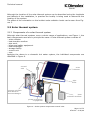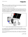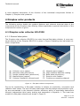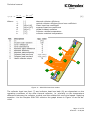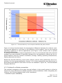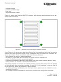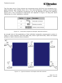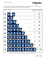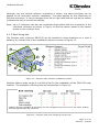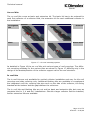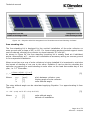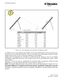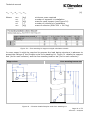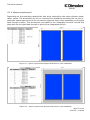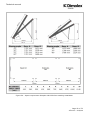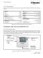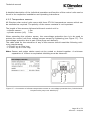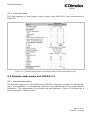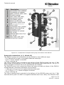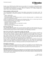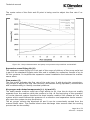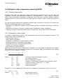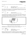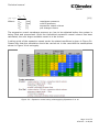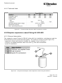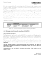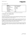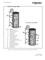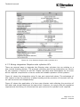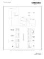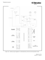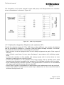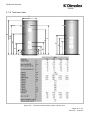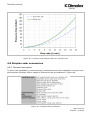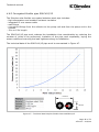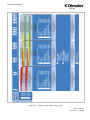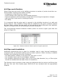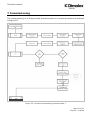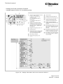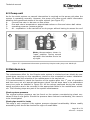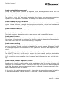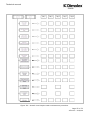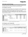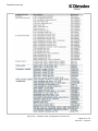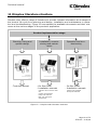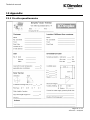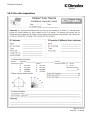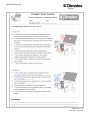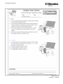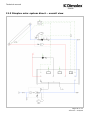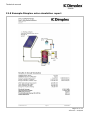
1
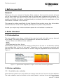
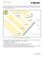
SOLAR
Technical Manual
Complete guide to Dimplex Solar
Page 1 of 72
ST0133 – A 02/09
Technical manual
SOLAR
1 Contents
1 CONTENTS
2
2 BEFORE YOU START
4
GENERAL
3 SOLAR THERMAL
3.1 INTRODUCTION
3.2 SOLAR RADIATION
3.1.1 Available solar radiation
3.1.2 Orientation
3.3 SOLAR THERMAL SYSTEM
3.3.1 Components of a solar thermal system
3.3.2 Function of a solar thermal system
4 DIMPLEX SOLAR PRODUCTS
4.1 DIMPLEX SOLAR COLLECTOR SOLC220
4.1.1 General description
4.1.2 Hydraulic collector connection
4.1.3 Roof fixing kits
4.1.4 Space requirement
4.1.4 Technical data
4.2 DIMPLEX SOLAR CONTROL UNIT SOLCU1/2/3
4.2.1 General description
4.2.2 Temperature sensors
4.2.3 Technical data
4.3 DIMPLEX SOLAR PUMP UNIT SOLPU1/2
4.3.1 General description
4.3.2 Pump connection
4.3.3 Technical data
4.4 DIMPLEX SOLAR EXPANSION VESSELS SOLEV
4.4.1 General description
4.4.2 Expansion vessel sizing
4.4.3 Technical data
4.5 DIMPLEX EXPANSION VESSEL FIXING KIT SOLVK1
4.5.1 General description
4.5.2 Technical data
4.6 DIMPLEX HEAT TRANSFER MEDIUM SOLHT20
4.6.1 General description
4.6.2 Technical data
4.7 DIMPLEX SOLAR CYLINDERS SCX
4.7.1 General description
4.7.2 Wiring integration Dimplex solar cylinders SCx
4.7.3 Hydraulic integration Dimplex solar cylinders SCx
4.7.4 Technical data
4
4
4
4
4
6
8
8
10
11
11
11
13
17
22
24
24
24
25
26
26
26
30
31
32
32
32
35
35
35
36
36
36
37
37
37
39
42
43
Page 2 of 72
ST0133 – A 02/09
Technical manual
SOLAR
4.8 DIMPLEX SOLAR ACCESSORIES
4.8.1 General description
4.8.2 Corrugated flexible pipe SOLFH10/15
4.8.3 Feed through tiles SOLFTT and SOLFTM
5 SYSTEM SIZING
5.1 REQUIRED INFORMATION
5.2 SIZING GUIDE
6 PIPE WORK
6.1 TYPE OF PIPE WORK
6.2 PIPE WORK SIZING
6.3 PIPE WORK PRESSURE DROP
6.4 PIPE WORK LIQUID CONTENT
6.5 PIPE WORK FIXATION
6.6 PIPE WORK INSULATION
44
44
45
46
47
47
47
49
49
49
50
50
51
51
7 COMMISSIONING
52
8 OPERATION
53
8.1 CONTROL UNIT
8.2 PUMP UNIT
53
55
9 MAINTENANCE
55
10 PRODUCT AND KIT LISTINGS
58
10.1 DIMPLEX SOLAR KITS
10.2 DIMPLEX SOLAR COMPONENTS
58
58
11 DIMPLEX LITERATURE STRUCTURE
60
12 APPENDIX
61
12.1 ON SITE QUESTIONNAIRE
12.2 ON SITE INSPECTION
12.3 DIMPLEX SOLAR SYSTEM DIRECT – OVERALL VIEW
12.4 DIMPLEX SOLAR SYSTEM INDIRECT – OVERALL VIEW
12.5 EXAMPLE DIMPLEX SOLAR SIMULATION REPORT
13 NOTES AND SKETCHES
61
62
65
66
67
72
Page 3 of 72
ST0133 – A 02/09
Technical manual
SOLAR
2 Before you start
General
Thank you for your interest in Dimplex Solar products. We trust this manual will give
you all the answers to the questions that you might have regarding the products. Although every care was taken to ensure the content of this manual is correct we do not
accept any liability for claims resulting directly or indirectly from the application of the
information contained in this manual.
This manual is written specifically for the Dimples Solar product range. Any information
contained therein must not be applied generally to any other solar products.
Should you require any further assistance please do not hesitate to contact us.
3 Solar thermal
3.1 Introduction
The sun supplies every day a multiple of the required world wide daily energy demand
to the earth. The energy of the sun is available in various forms such as:
- direct, diffuse and reflected solar radiation
- wind
- waves
- the ground and in other forms.
Solar thermal systems convert the energy incident from the sun on an absorber surface
into sensible heat in form of hot water. Depending on the temperature required and
achieved, this hot water can be used for a whole range of applications as summarised in
Figure 1.
Figure 1 – Approximate temperature ranges of some solar thermal applications
3.2 Solar radiation
3.1.1 Available solar radiation
Solar thermal systems can only utilise the energy from the sun in form of solar radiation.
The solar radiation can be incident on the solar panels in various forms which are shown
Page 4 of 72
ST0133 – A 02/09
Technical manual
SOLAR
in Figure 2, namely direct, reflected and diffuse radiation. The various types of radiation
can occur in isolation but in most cases the radiation incident on a solar thermal collector is a combination thereof.
<200 W/m²
strong
diffuse
<600 W/m²
diffuse
<1000 W/m²
direct
<1200 W/m²
direct + reflected
Figure 2 – Forms of incident solar radiation
The solar radiation available outside the earth’s atmosphere, the so called extraterrestrial radiation, has a density of 1367 W/m². Depending on:
- the location of the solar system
- the time of day and year
- the “obstacles” in the atmosphere such as cloud cover and pollution
- and the inclination of the solar system in relation to the sun
this value varies strongly. A map of the United Kingdom and Ireland is shown in Figure
3, indicating average annual solar energy gains on the horizontal surface.
Page 5 of 72
ST0133 – A 02/09
Technical manual
SOLAR
Figure 3 – UK and Ireland irradiation map (horizontal surface)
3.1.2 Orientation
The solar irradiance shown in Figure 3 is an average value incident on the horizontal
surface. As mentioned above, depending on the orientation and inclination of the solar
collector the incident radiation onto the collector surface can vary although it might be
in the same location.
The terminology used to describe the exact location and orientation of a solar collector
is described in Figure 4. The terms indicate:
- longitude: geographic coordinate for East/West measurement
- latitude: geographic coordinate North or South of the equator
- slope: angle between the horizontal and the collector plane
- azimuth: angle between South and the perpendicular to the collector pane (West
+90°, South =0°, East -90°)
Page 6 of 72
ST0133 – A 02/09
Technical manual
SOLAR
Zenith
SUN
La
ti
tud
e
Slope
N
W
e
ud
git
n
Lo
Azimuth
S
E
Figure 4 – Terminology to describe location and orientation of solar thermal panel
Figure 5 – Effect of orientation on incident radiation levels
Page 7 of 72
ST0133 – A 02/09
Technical manual
SOLAR
Although the location of the solar thermal system can be described using the longitude
and latitude of the installation, in practise the locality is being used to determine the
location of the system.
The effect of the orientation on the incident solar radiation levels can be seen from Figure 5.
3.3 Solar thermal system
3.3.1 Components of a solar thermal system
Although solar thermal systems cover a whole range of applications, see Figure 1, the
basic components used are in principle the same. A solar thermal system consists of:
- solar collector
- heat transfer medium
- pipe work
- pump and safety equipment
- heat exchanger
- storage facility
- control unit
- user
Applying the above to a domestic hot water system, the individual components are
identified in Figure 6.
control
unit
solar
collector
pipe
work
storage cylinder
with build in
heat exchanger
heat
transfer medium
pump and safety
equipment
Figure 6 – Solar system components overall view
Page 8 of 72
ST0133 – A 02/09
Technical manual
SOLAR
Each component in the solar thermal system fulfils a specific function which is described
below:
Solar thermal collector
The solar thermal collector receives the solar radiation, converts it into thermal energy
and passes it on to the heat transfer fluid.
Heat transfer fluid
The heat transfer fluid circulates through the solar collector, the pipe work and the heat
exchanger. It transfers the energy gained by the collector into the storage device. The
heat transfer fluid has additional properties such as frost protection and anti-corrosion
inhibitors to ensure a long and reliable operation of the solar thermal system.
Pipe work
The pipe work connects the various components of the solar thermal system to allow
the heat transfer medium to transport the energy from the collector to the storage device. The pipe work must be insulated and both, the pipe work and the insulation must
be of appropriate material for solar thermal applications.
Pump and safety equipment
The pump and safety equipment are combined in the pump unit. Beside the actual circulation pump the pump unit contains a flow meter, flush and fill point, air separator,
non return valves, manual thermometers, isolating valves, pressure relief valve, pressure gauge and the connection point for the expansion vessel.
Heat exchanger
The heat exchanger allows a hydraulic separation of systems but allows the transfer of
energy between the two systems, i.e. the solar circuit and the wholesome water. In a
domestic solar thermal hot water system the heat exchanger is usually in form of a coil
immersed in the wholesome water inside the hot water cylinder.
To ensure the solar thermal system works at its optimum efficiency, the heat exchanger
has to be sufficiently sized and positioned correctly within the hot water cylinder.
Storage facility
The storage facility is most likely to be a domestic hot water cylinder or a buffer vessel.
As the solar thermal system will not always be able to supply all of the required energy,
it is important that an auxiliary heating system is available to boost the system as and
when required.
The storage facility should be of such design that all energy sources can work independent of each other without compromising each others efficiencies, giving solar thermal the priority to allow for maximum energy gain.
Control unit
The control unit has the primary function of switching the circulation pump on and off
ensuring that the maximum amount of energy is being transferred from the solar thermal collector into the storage facility.
The control unit is usually also the user interface with the system and has therefore a
display and additional functions to ease the operation, maintenance and control of the
system.
Page 9 of 72
ST0133 – A 02/09
Technical manual
SOLAR
User
The user varies from installation to installation but has a big influence on the operation
of the solar thermal system. However, the system has all components to ensure the
provision of the comfort levels that the user expects.
3.3.2 Function of a solar thermal system
Bearing in mind the function of the individual components, the function of a solar thermal system is in principle very simple. Based on two measured temperatures, one in
the hottest (T1) and one in the coldest (T2) part of the system, the control unit
switches the pump either on or off depending on the temperature difference between T1
and T2 and the temperature reached in the storage device. The location of the temperature sensors is indicated in Figure 7.
T1
T2
Figure 7 – Location of temperature sensors in solar thermal system
If T1 is greater than T2 plus an additional temperature differential (called ΔT ‘delta T’),
the circulation pump is being switched on by the control unit to transfer the energy
from the collector into the storage device. As soon as this on condition is not given, the
pump is being switched off.
The solar control unit also ensures that the water in the cylinder is not being heated
above a set temperature which can be freely chosen and is measured by the temperature sensor T2.
Page 10 of 72
ST0133 – A 02/09
Technical manual
SOLAR
A more detailed description of the function of the individual components follows in
Chapter 4, Dimplex solar products.
4 Dimplex solar products
The following section details the product features and relevant technical data of the
components of the Dimplex solar offering. Where applicable a general description of the
component’s function is given.
4.1 Dimplex solar collector SOLC220
4.1.1 General description
The Dimplex solar collector SOLC220 is a solar thermal flat plate collector. A cross sectional drawing of the Dimplex SOLC220 is given in Figure 8 detailing the individual collector components.
(A)
(B)
(C)
(D)
(E)
Collector cover (glass)
Absorber plate (aluminium)
Powder coated frame (aluminium)
Manifold pipe (copper)
Collector insulation (mineral wool)
(F)
(G)
(H)
(I)
(J)
Meander pipe (copper)
High selective absorber coating
Back plate (aluminium)
Secure cover fixation
Continuous mounting channel
Figure 8 – Flat plate collector components
Due to its construction, a flat plate collector is subject to conduction, convection and
radiation heat losses. The sum of these heat losses and the design and production quality are summarised in the thermal collector efficiency which is empirically determined
through independent third party testing and expressed in Equation 1. The heat loss
modes of a flat plate collector are shown in Figure 9.
Page 11 of 72
ST0133 – A 02/09
Technical manual
SOLAR
η = η 0 − a1 ⋅
Where:
(t − t )2
tm − ta
− a2 ⋅ m a
G
G
η
η0
a1
a2
G
tm
ta
[-]
[-]
[W/m²/K]
[W/m²/K²]
[W/m²]
[°C]
[°C]
[1]
thermal collector efficiency
optical collector efficiency/zero loss coefficient
linear heat loss coefficient
squared heat loss coefficient
global incident radiation
collector middle temperature
collector ambient temperature
9
7
6
5
1
8
2
3
4
Figure 9 – SOLC220 heat loss modes
The collector heat loss front (7) and collector heat loss back (8) are dependant on the
operating conditions of the solar thermal collector, i.e. primarily on the temperature
difference between the collector module and the ambient air and wind speed. Applying
equation 1 to the Dimplex SOLC220 collector the graph shown in Figure 10 can be derived.
Page 12 of 72
ST0133 – A 02/09
Technical manual
SOLAR
Figure 10 – Thermal efficiency curve Dimplex SOLC220 flat plate collector
Figure 10 shows that the higher the temperature difference between the collector module and the ambient is, the lower is the efficiency of the product. Due to the required
operating conditions of various applications (see Figure 1) the collector has to operate
at varying efficiencies.
In general central heating support applications are not recommended with solar thermal
except if the whole system is especially designed for the application offering all the required features such as collector orientation, storage, heating operating temperatures,
heating demand and others.
Beside the thermal efficiency of the solar collector various other parameters are of importance for the correct application thereof. All of these parameters are determined in
accordance with EN12975 and some of them are detailed in Figure 25, Technical details
Dimplex SOLC220.
4.1.2 Hydraulic collector connection
The hydraulic integration of the solar thermal collector in the overall system is critical to
ensure the most efficient and reliable operation of the installation. When integrating the
collector, the following aspects have to be considered:
- installation space availability
Page 13 of 72
ST0133 – A 02/09
Technical manual
SOLAR
-
collector design
collector pressure drop
flow rate
required system output
Figure 11 shows the Dimplex SOLC220 collector with the pipe work attached to the absorber plate indicated.
A
B
C
D
Figure 11 – Absorber pipe work Dimplex SOLC220 collector
From Figure 11 it can be seen that the collector has 4 connections which can be used to
connect the flow and return pipes of the installation and to connect the collectors between each other. The 4 connections offer the following features:
- one collector for small or large installations
- left hand or right hand side connection of single collector installations
- up to 10 collectors directly connected together
- collectors connected in parallel to each other, thus low overall pressure drop of array
- same collector for vertical or horizontal installations
The sensor pockets to connect the collector sensor T1 from the control unit are always
on the side with the connections marked (A) and (C). It is important to ensure that all
of the pipe work within the collector is being utilised:
- for single collector installations, the flow and return pipes must be installed on connections (B) and (D).
- for multiple collector installations the sensor pockets must always face outwards.
Page 14 of 72
ST0133 – A 02/09
Technical manual
SOLAR
The flow and return of the collector are connected using a 800mm long insulated corrugated stainless steel flexible hose (9.1). The interconnections consist of short flexible
bellows (10.1). The remaining connections are to be blanked off using the blanking
pieces (9.2). The connections components are depicted in Figure 12 using the same
references as in the installation manuals.
Figure 12 – Connection components Dimplex SOLC220 collector
An overall view of the application of the individual connection components is given in
Figure 13 (two collectors, flow left hand side, return right hand side). Note: the sensor
pockets on both collectors face outwards.
Figure 13 – Typical connection of Dimplex SOLC220 collector
Page 15 of 72
ST0133 – A 02/09
Technical manual
SOLAR
An overall view of possible collector connections is given in Figure 14 detailing also the
pressure drop at nominal low-flow and high-flow flow rates.
No. of collectors
Flow rate Pres. drop
[mbar]
[l/min]
1
1
2
150
325
2
2
4
150
330
3
3
6
150
330
4
4
8
160
340
5
5
10
160
340
6
6
12
170
350
7
7
14
185
385
8
8
16
195
400
9
9
18
200
420
10
20
10
210
500
Figure 14 – Collector connection options, flow rates and pressure drop
Page 16 of 72
ST0133 – A 02/09
Technical manual
SOLAR
Although only the vertical collector orientation is shown, the same principles can be
applied to the horizontal collector installation. The same applies for the positioning of
the flow and return, it can be changed from left to right hand side as long as the sensor
(indicated by dot) is moved accordingly.
Note: Up to 5 collectors can also be connected single sided with the orientation of the
individual collectors as shown in Figure 14 and the sensor placed in the sensor
pocket on the collector flow.
4.1.3 Roof fixing kits
The Dimplex solar collectors SOLC220 can be installed in most situations on or near a
building. An overall view of the installation options is shown in Figure 15.
B
A
E
C
H
F
G
D
Figure 15 – Dimplex Solar collector installation options
Dimplex offers a wide range of roof fixing kits for the installation of the SOLC220 solar
collector. The available roof fixing kits are summarised in Figure 16.
Flashing kits are available as accessory for the integrated roof kits to cover the sides, bottom
and the gap between the collectors.
Figure 16 – Dimplex solar roof fixing kits overall view
Page 17 of 72
ST0133 – A 02/09
Technical manual
SOLAR
On roof kits
The on roof kits come as basic and extension kit. The basic kit has to be ordered for
each first collector of a collector field, the extension kit for each additional collector in
the installation.
Corrugated
tile
Plain tile
Slate
Sheet metal
Figure 17 – On roof mounting options
As detailed in Figure 16 the on roof kits suit various types of roof coverings. The different mounting methods for the various tiles are shown in Figure 17 differing only in the
design of the bracket/fixation of the collector support rail to the roof structure.
In roof kits
The in roof kits are only available for vertical collector installation and vary for tile roof
coverings and slate covering only. Additional flashing kits are available to complement
the integrated roof kits, covering the pipe work on the side of the collector, the fixing
brackets at the bottom and the gap between the collectors.
The in roof kits and flashing kits are not sold as basic and extension kits but come as
complete kits for 2, 4 and 6m² installations. Should a larger collector field be installed,
further extension kits are available.
Page 18 of 72
ST0133 – A 02/09
Technical manual
SOLAR
Integrated roof kit
without flashings fitted
Integrated roof kit
with flashings fitted
Figure 18 – Dimplex SOLC220 integrated roof kit without and with flashing kit fitted
Free standing kits
The free standing kit is designed for the vertical installation of the solar collector on
even ground with a slope of 45° to 60°. For lower sloping angles shorted support struts
can be ordered, allowing the collector to slope between 30° and 40°.
As shown in Figure 24, the free standing mounting kit is usually fixed at 4 individual
points. Alternatively a U – section rail is available as accessory aiding on uneven ground
or for suspended installation.
When more than one row of solar collectors is being installed it is important to minimise
the impact of shading of one row to the other. Equation 2 can be used to calculate the
optimum row spacing to avoid shading at solar noon on the least favourable day of the
year, i.e. 21st December.
p_c =
1870mm ⋅ sin (180° − (β + α s ))
sin α s
Where:
p_c
β
αs
[mm]
[°]
[°]
[2]
pitch between collector rows
sloping angle of solar collector
solar altitude angle
The solar altitude angle can be calculated applying Equation 3 or approximating it from
Figure 19.
α s = 90° − (cos φ ⋅ cos 23.45° + sin φ ⋅ sin 23.45°)
Where:
αs
φ
[°]
[°]
[3]
solar altitude angle
latitude of installation
Page 19 of 72
ST0133 – A 02/09
Technical manual
SOLAR
Figure 19 – Free standing kit row distance calculation details
In addition to the row distance the fixation of the free standing kit to the mounting surface has to be considered carefully. Due to the shape of the flat plate collector considerable wind forces can act on the free standing kit installation.
Ideally the free standing kit is bolted to a fixed structure. However, this is not always
practicable, especially when the roof surface must not be penetrated for water tightness reasons.
Equation 4 is to be used to calculated the required mass to securely locate the free
standing kit. The required parameters can be found in Figure 20.
Note: the stated parameters are only valid for the wind speeds stated in Figure 20. It is
the responsibility of the installer/mechanical engineer to validate these figures for the
individual installation. Dimplex does not accept any liability for damage to material,
buildings or persons resulting from free standing installations not being sufficiently supported.
Page 20 of 72
ST0133 – A 02/09
Technical manual
SOLAR
mtot = n spt ⋅ m spt − ncol ⋅ mcol
Where:
mtot
nspt
mspt
ncol
mcol
[kg]
[-]
[kg]
[-]
[kg]
[4]
minimum mass required
number of supports in installation
mass for each support (see Figure 20)
number of collectors in installation
mass of collector (SOLC220 = 34.5 kg)
Figure 20 – Free standing kit support weight calculation details
In some cases it might be required to prepare the load baring structure in advance to
accept the fittings of the Dimplex solar free standing kit. Figure 21 details the support
feet (4x for each collector) and the free standing bottom bar (2x for each collector).
Support feet
Free standing bottom bar
Figure 21 – Fixation details Dimplex solar free standing kit
Page 21 of 72
ST0133 – A 02/09
Technical manual
SOLAR
4.1.4 Space requirement
Depending on the mounting method the foot print required by the solar collector installation varies. The dimension for the on roof and free standing mounting kits do not include the space required to fit the connection pipes as these vary depending on the pipe
feed through chosen. The dimensions provided for the integrated roof kits include the
pipe work as the pipe feed through is part of the integrated roof kit.
Figure 22 – Space requirement Dimplex SOLC220 on roof installation
Figure 23 – Space requirement Dimplex SOLC200 in roof installation
Page 22 of 72
ST0133 – A 02/09
Technical manual
SOLAR
Figure 24 – Space requirement Dimplex SOLC220 free standing installation
Page 23 of 72
ST0133 – A 02/09
Technical manual
SOLAR
4.1.4 Technical data
Figure 25 summarises the key technical data of the Dimplex SOLC220 solar thermal
collector.
Figure 25 – Technical data Dimplex SOLC220 collector
4.2 Dimplex solar control unit SOLCU1/2/3
4.2.1 General description
Dimplex solar offer a range of solar control units with differing input and output options
and functionality. All control units operate on the basic principles described in chapter
3.3.2. Figure 26 shows the SOLCU1 control unit detailing the main components which
are common to all Dimplex solar control units.
LCD display
- animated
- backlit
- controller operation
and system settings
Operating switch
× ON
- AUTO
Ø OFF
Operating buttons
- scroll up
- SET
- scroll down
SOLCU1
Connections
- mains supply
- relay output(s)
- sensor inputs
Figure 26 – Dimplex solar control unit overall view
Page 24 of 72
ST0133 – A 02/09
Technical manual
SOLAR
A detailed description of the individual operation and function of the control units can be
found in the respective installation and operating instructions.
4.2.2 Temperature sensors
All Dimplex solar control units come with three PT1000 temperature sensors which can
be extended as required. The polarity of the sensor contacts is not important.
The length of the sensors delivered with each control unit is:
- collector sensor:
1.5m
- cylinder sensors (x2): 3.0m
When extending the collector sensor, the overvoltage protection box is to be used to
protect the control unit from voltage surges caused by lightening (see Figure 27). The
overvoltage protection box is part of the pump unit delivery.
The cable used for the extension of any of the sensors should meet the following minimum requirements:
- 0.75mm² up to 50m long
- 1.50mm² up to 100m long
To controller
From Collector
Note: Sensor and mains cables must not be routed or ducted together. A minimum
separation of 100mm or equivalent shielding must be observed.
Figure 27 – Connection of collector temperature sensor to overvoltage protection box (included with
Dimplex solar pump unit SOLPU1/2)
Page 25 of 72
ST0133 – A 02/09
Technical manual
SOLAR
4.2.3 Technical data
The main features of the Dimplex solar control units SOLCU1/2/3 are summarised in
Figure 28.
Figure 28 – Technical data overall view Dimplex solar control units SOLCU1/2/3
4.3 Dimplex solar pump unit SOLPU1/2
4.3.1 General description
The Dimplex solar pump units SOLPU1 and SOLPU2 comprise a number of features aiding in the installation, commissioning, operation and maintenance of the solar thermal
installation. The components of the pump unit are depicted in Figure 29 followed by a
brief description of their function.
Page 26 of 72
ST0133 – A 02/09
Technical manual
SOLAR
02
01
03
16
04
15
05
14
13
06
12
07
08
11
09
10
Figure 29 – Components of Dimplex solar pump unit SOLPU1 and SOLPU2
Pump unit connections (1, 2, 10 and 13)
The SOLPU1 pump unit connections can be utilised in three different ways:
- 3/4” flat seal at the end of corrugated stainless steel pipe
- 3/4”F x 22mm straight connection
- 15mm reducing set
The 15mm reducing set is included in the delivery of the SOLPU1 pump unit, the ¾” flat
seal is part of the delivery of the Dimplex solar flexible hose SOLFH10/15. The ¾”F x
22mm straight connection has to be provided by the installer.
The SOLPU2 pump unit connections follow the same principle as those of the SOLPU1
except that the connection diameters are increased:
- 1” flat seal at the end of corrugated stainless steel pipe
- 1”F x 22mm or 1”F x 28mm straight connection
- 22mm reducing set
The 22mm reducing set is included in the delivery of the SOLPU2 pump unit, the 1” flat
seal should be part of a DN20 corrugated stainless steel hose. Note, the Dimplex solar
Page 27 of 72
ST0133 – A 02/09
Technical manual
SOLAR
flexible hose SOLFH10/15 is DN16 and only provides ¾” connections. Should this product be applied to the SOLPU2 a 1” to ¾” reducer has to be provided with sufficient sealing surface for the flat seal to sit against. The 1”F x 22mm or 1”F x 28mm straight connection has to be provided by the installer.
6 bar pressure relief valve (3)
The 6 bar pressure relief valve is part of the safety components in the solar circuit. Its
correct application is therefore important. The discharge pipe from the relief valve must
be:
- 22mm copper pipe
- with no more than 2 bends
- terminating safely (it is recommended to end the discharge pipe in a suitable vessel
and not to discharge to drain)
Should the pressure relief valve open and discharge fluid, this is a clear sign that the
system is malfunctioning. The malfunction can be caused by:
- cold fill pressure of system too high
- expansion vessel too small
- expansion vessel pre-charge not adjusted correctly
- expansion vessel faulty
- solar collector array considerably oversized
Pressure gauge (4)
The pressure gauge indicates the current pressure inside the solar thermal loop. In a
properly designed, installed, commissioned and operated system the pressure indicated
by the pressure gauge should remain constant in all operating conditions.
Non return ball valve, temperature gauge (5 and 16)
The non return valve is critical in a solar thermal system to avoid gravity circulation at
times when the cylinder is warmer than the collector as during night time hours. The
non return valves avoid unwanted gravity circulation from the cylinder to the collector,
thus losing energy from the system. As both the flow and the return path of the
SOLPU1/2 pump units have a non return valve the circulation of flow from the collector
to the cylinder can be eliminated when the pump is switched off.
The non return valves have an integrated ball valve which can be closed by turning the
handle with the integrated manual thermometer by 90°. This allows the temporarily
isolation of certain parts of the system for maintenance purposes. The non return valves
can be opened for venting or draining purposes by turning the handles to 45°.
Circulation pump (6)
Two different circulation pumps are being utilised in the SOLPU1 and the SOLPU2 pump
station to increase the capacity of the range. The characteristic pump curves for the
pumps used are shown in Figure 30 along side the pressure drop of each pump unit.
Flush and fill point (7)
The flush and fill point allows the connection of the Dimplex solar flush and fill pump
SOLFFP110/240 for the flushing and filling of the solar loop. Should a hand pump being
used it is also to be connected at this point but not all three valves are being made use
of during the filling process.
Page 28 of 72
ST0133 – A 02/09
Technical manual
SOLAR
The centre valve of the flush and fill point is being used to adjust the flow rate if required.
Figure 30 - Pump characteristics and pump unit pressure drop SOLPU1 and SOLPU2
Expansion vessel fixing kit (8)
The expansion vessel fixing kit is not part of the scope of delivery of the pump units but
is part of the standard Dimplex solar kits and is suitable for expansion vessels of up to
24 litre contents. It simplifies the expansion vessel installation and reduces the maintenance effort.
Flow meter (9)
The flow meter indicates the flow rate of the solar loop. It aids during the commissioning process to adjust the flow rate correctly and assists during operation, maintenance
and troubleshooting to identify eventual problems.
Air purger and related components (11, 14 and 15)
The heat transfer medium used has a high affinity to air, thus the air does not readily
separate from the medium while the medium is cold. At the beginning of the operation
of a solar thermal system therefore the heat transfer medium will release air into the
system which would without the presence of a collection and separation device eventually cause the system to stop functioning.
The air purger collects the dissolved air and it can be conveniently vented from the
manual bleed valve. The flexible bleed valve discharge tube ensures that the venting
process can be done safely.
Page 29 of 72
ST0133 – A 02/09
Technical manual
SOLAR
Insulation cover (12)
The insulation cover avoids unnecessary heat loss from the solar loop and gives the
pump unit its aesthetically pleasing appearance.
4.3.2 Pump connection
The connection of the circulation pump to the control unit has to be considered in its
application for:
- open vented hot water systems
- closed unvented hot water systems
When installing the solar thermal system in conjunction with an open vented system,
the pump can be directly wired into the control unit as shown in the control unit manual.
When using an unvented hot water system, the pump has to be wired through the twin
thermostat at the cylinder. Figure 31 shows the wiring schematic utilising the 4-way
wiring centre provided with the pump unit.
Control Unit
Solar pump
L
N
Twin tank
thermostat
2
1
C
2
1
C
Figure 31 – Wiring of solar circulation pump to control unit utilising 4-way wiring centre
The use of a motorised two port valve is not required as long as:
- the pump unit has a non return valve in flow and return
- the circulation pump is connected using the twin thermostat mounted to the cylinder
- the cylinder is situated lower in the property than the lowest part of the solar collector
Page 30 of 72
ST0133 – A 02/09
Technical manual
SOLAR
Should the above conditions not be given, the motorised two port valve has to be installed in series to the twin thermostat.
4.3.3 Technical data
Figure 32 – Technical data Dimplex solar pump unit SOLPU1 and SOLPU2
Page 31 of 72
ST0133 – A 02/09
Technical manual
SOLAR
4.4 Dimplex solar expansion vessels SOLEV
4.4.1 General description
Dimplex solar offer an extensive range of expansion vessels from 18 to 80 litres. All
expansion vessels are particularly suited for the application in solar thermal systems
with a high temperature resistant membrane which has also excellent diffusion barrier
characteristics in conjunction with the heat transfer medium used in solar thermal systems.
In solar thermal systems the expansion vessels has a number of functions to ensure the
safe and reliable operation of the system:
- absorption of additional system volume when system is heating up during normal operation
- absorption of steam volume of system when installation enters stagnation
- holding of medium reserve when system temperature drops below fill temperature
4.4.2 Expansion vessel sizing
A number of parameters have to be considered when sizing the expansion vessel. The
parameters to be considered are:
- total system volume
- static height of system
- expansion coefficient of heat transfer medium
- opening pressure of pressure relief valve
- required pressure in highest system point
- number of collectors installed
- fluid content of each collector
Applying the above system parameters, Equation 5 can be used to calculate the expansion vessel size VEV, the cold fill pressure of the system and the membrane pre-charge
pressure of the expansion vessel.
V EV =
(V pc + Vep + n ⋅ Vcol )⋅ ( prv + 1)
Where:
[5]
( p rv − p pc ) ⋅ 0.6
VEV
Vpc
Vep
n
Vcol
prv
ppc
[l]
[l]
[l]
[-]
[l]
[bar]
[bar]
minimum expansion vessel volume
pre-charge volume
system expansion volume
number of collectors connected to expansion vessel
collector volume (SOLC220 = 1.7 litre)
relief valve pressure
cold fill pressure
Equation 6 is to be applied to determine the expansion vessel pre-charge volume Vpc.
V pc = 0.005 ⋅ Vsys ≥ 3litre
Where:
Vpc
Vsys
[l]
[l]
[6]
pre-charge volume
total system volume
Page 32 of 72
ST0133 – A 02/09
Technical manual
SOLAR
The expansion volume of the system Vep can be calculated using Equation 7.
Vep = Vsys ⋅ β
Where:
[7]
Vep
Vsys
β
[l]
[l]
[-]
system expansion volume
total system volume
heat transfer medium expansion coefficient (0.00085)
The pressure relief valve pressure prv can as first approximation be used as 6 bar. However, to allow for some tolerance it is recommended to calculate the pressure relief
valve pressure prv in accordance with Equation 8.
p rv = pop ⋅ (1 − 0.1)
Where:
prv
pop
[8]
[bar]
[l]
relief valve pressure
opening pressure of relief valve (6 bar)
The last parameter to be calculated for use in Equation 5 is the cold fill pressure ppc of
the system. The cold fill pressure ppc depends on the static height hstat of the solar
thermal system and the required pressure in the highest system point pmin. The definition of the static height hstat is depicted in Figure 33.
hstat
Figure 33 – Definition of static height of solar system
The pressure in the highest system point pmin should be between 1 and 1.5 bar. The
cold fill pressure ppc can therefore be calculated as shown in Equation 9.
p pc = pmin + 0.1 bar
⋅ hstat
m
Where:
ppc
pmin
hstat
[bar]
[bar]
[m]
[9]
cold fill pressure
pressure in highest system point
static height of system
Equation 9 concludes the calculation of parameters required for Equation 4 to calculate
the expansion vessel volume VEV. To be able to commission the expansion vessel, the
membrane pre-charge pressure pmp has to be calculated as shown in Equation 10.
Page 33 of 72
ST0133 – A 02/09
Technical manual
SOLAR
p mp = p pc ⋅
Where:
V EV − V pc
[10]
V EV
pmp
ppc
VEV
Vpc
[bar]
[bar]
[l]
[l]
membrane pressure
cold fill pressure
expansion vessel volume
pre-charge volume
The expansion vessel membrane pressure pmp has to be adjusted before the system is
being filled and pressurised. Once the theoretical expansion vessel volume has been
calculated, the next larger available vessel is to be chosen.
A sizing guide of the expansion vessel under the stated conditions is given in Figure 34.
Please note that the calculation should be carried out in the case that the assumptions
shown in Figure 34 do not apply.
Figure 34 – Expansion vessel sizing chart applying Equations 5 to 10
Page 34 of 72
ST0133 – A 02/09
Technical manual
SOLAR
4.4.3 Technical data
Figure 35 – Technical data Dimplex SOLEV expansion vessels
4.5 Dimplex expansion vessel fixing kit SOLVK1
4.5.1 General description
The expansion vessel fixing kit SOLVK1 aids with the installation, maintenance and decommissioning of the solar thermal system. The product consists of (see Figure 36):
- expansion vessel wall bracket (suitable for vessels of up to 440mm)
- 500mm corrugated stainless steel hose with ¾” flat seal connections
- quick fit connection
01
02
03
Figure 36 – Components Dimplex solar expansion vessel fixing kit SOLVK1
Page 35 of 72
ST0133 – A 02/09
Technical manual
SOLAR
It is not recommended to fit vessels larger than 24 litres using the expansion vessel
fixing kit as faulty vessels gain considerably in weight and the wall bracket would not
support the additional weight.
The 500mm corrugated stainless steel hose allows the expansion vessel to be directly
connected to the expansion vessel connection port of the Dimplex solar pump units
SOLPU1 and SOLPU2.
The quick fit connection is a combined retainer and vessel connection. The vessel connection incorporates a fast acting two way valve operating always in the direction of
lower pressure. Should the vessel need maintained or replaced, the fitting eliminates
the need for the system to be drained down as it will close as soon as the vessel disconnects from the circuit.
Once the vessel is maintained or replaced the same fitting can be used to reconnect the
vessel to the system.
4.5.2 Technical data
Figure 37 – Technical data Dimplex expansion vessel fixing kit SOLVK1
4.6 Dimplex heat transfer medium SOLHT20
4.6.1 General description
The Dimplex solar heat transfer medium SOLHT20 is a ready to use 1.2-polypropylene
glycol fluid for solar thermal installations. The product has particularly good characteristics at higher temperatures where the liquid inhibitors resolve more readily back into
the solution than solid inhibitors.
This increases the useable life of the product, reduces the acidity of the medium when
at high temperatures and ensures the frost protection function is not being lost. In addition the inhibitors will not solidify inside the solar system and block ducts with small
diameters.
The heat transfer medium is ready mixed and must not be diluted on site. When replacement of lost medium is required it is important to ensure that only the same medium is being used.
Dimplex provide a test kit, SOLHTTK, to monitor the condition of the medium over the
course of its life.
Page 36 of 72
ST0133 – A 02/09
Technical manual
SOLAR
4.6.2 Technical data
Figure 38 – Technical data Dimplex solar heat transfer medium SOLHT20
4.7 Dimplex solar cylinders SCx
4.7.1 General description
Dimplex offer a range of direct electric and indirect heated solar cylinders from 175 litre
to 305 litre overall volume. An overall view of the products is given in Figure 39 and a
summary of the key features is given in Figure 40.
The inlet and outlet pipe routing of the cylinders is in such a way that during water draw
offs the stratification of the stored hot water is effected as little as possible, ensuring
the maximum amount possible to be drawn at high water temperatures.
In addition, the sloped outlet pipe of the cylinder minimises the required installation
height and reduces the heat losses from the unit to a minimum.
The corrugated stainless steel solar coil ensures high heat transfer rates and minimises
the risk of lime build up. The position of the solar coil ensures maximum usage of the
available cylinder volume without compromising the comfort of sufficient auxiliary volume available.
Page 37 of 72
ST0133 – A 02/09
Technical manual
SOLAR
SCx175/215/255/305sd
18
01
02
04
16
07
17
05
SCx175/215/255/305si
12
06
03
13
15
14
18
01
04
02
16
17
11
08
05
10
09
12
07
03
13
15
14
Figure 39 – Overall view Dimplex solar SCx unvented stainless steel cylinders
Page 38 of 72
ST0133 – A 02/09
Technical manual
SOLAR
Figure 40 – Key features Dimplex solar cylinders SCx
4.7.2 Wiring integration Dimplex solar cylinders SCx
There are several ways to integrate the Dimplex solar cylinders into an existing or a
new central heating system. The principle plumbing and wiring schematics are shown
for two systems in Figures 41 and 42. Please note that these illustrations do not show
all the required components to ensure a safe and reliable operation of the systems.
Figure 41 shows the integration using 2x two port motorised valves. The advantage of
this system is that the provision of space heating and the provision of domestic hot water can be carried out independently.
Figure 42 shows the application of a three way diverter valve allowing the provision of
hot water and central heating at the same time. However, to comply with the regulative
requirements the fitting of a motorised two port valve to the cylinder is still required.
Page 39 of 72
ST0133 – A 02/09
Technical manual
SOLAR
Figure 41 – Auxiliary loop integration 2x motorised two port valve
Page 40 of 72
ST0133 – A 02/09
Technical manual
SOLAR
Figure 42 - Auxiliary loop integration 1x motorised two port valve and mid-position valve
Page 41 of 72
ST0133 – A 02/09
Technical manual
SOLAR
The integration of the solar thermal control and pump unit independent from manufacturer nomenclature is shown in Figure 43.
Figure 43 – Solar loop integration
4.7.3 Hydraulic integration Dimplex solar cylinders SCx
Should the cylinder range of 175 to 305 litres not be sufficient, any number of cylinders
can be connected in parallel or in series to achieve higher storage volumes. The following should be observed when connecting the cylinders:
- each cylinder must be equipped with its own safety equipment as part of the scope of
delivery
- each cylinder must have its own save discharge in accordance with building regulations
- connect the cylinders on the potable and energy supply side in series when an even
demand is required over a period of time
- connect the cylinders on the potable and energy supply side in parallel when peak
demands are expected exceeding the capacity of an individual cylinder with its supply
- when installing larger systems ensure a risk assessment is carried out in accordance
with approved code of practise L8 from the HSE
- ensure each cylinder is accessible for maintenance and replacement work as required
- ensure the hydraulic circuit from the solar loop is balanced, i.e. the correct flow rate is
achieved through each coil
Page 42 of 72
ST0133 – A 02/09
Technical manual
SOLAR
4.7.4 Technical data
P
C
I
G
H
M
O
J
L
A
B
K
E
D/N
F
Figure 44 – Technical data Dimplex solar cylinder SCx
Page 43 of 72
ST0133 – A 02/09
Technical manual
SOLAR
Figure 45 – Pressure drop Dimplex solar SCx cylinder coils
4.8 Dimplex solar accessories
4.8.1 General description
To aid in the installation, commissioning, maintenance and the realisation of more complex systems Dimplex offer a range of accessories as summarised in Figure 46.
Figure 46 – Dimplex solar accessories
Page 44 of 72
ST0133 – A 02/09
Technical manual
SOLAR
4.8.2 Corrugated flexible pipe SOLFH10/15
The Dimplex solar flexible corrugated stainless steel pipe includes:
- high temperature and weather resistant insulation
- integrated 2 core sensor cable
- wall fixings
- connection fittings from the collector to the pump unit and from the pump unit to the
cylinder
- 10m or 15m length.
The SOLFH10/15 pipe work reduces the installation time considerably by reducing the
number of joints to be performed, insulation of the pipe work separately, laying the
sensor cable and ensuring the leak tightness along its installation.
The technical data of the SOLFH10/15 pipe work is summarised in Figure 47.
~100mm
~45mm
Figure 47 – Technical data Dimplex flexible hose SOLFH10/15
Page 45 of 72
ST0133 – A 02/09
Technical manual
SOLAR
4.8.3 Feed through tiles SOLFTT and SOLFTM
The Dimplex solar feed through tiles are suitable for corrugated and plain tiles, slate
roof coverings and sheet metal coverings depending on the type chosen:
- SOLFTT: corrugated and plain tile, slate roof covering
- SOLFTM: sheet metal roof covering, plain or corrugated
For each pipe feed through one tile of the appropriate type is required. The product
allows pipes and cables from 0 to 35mm to be fed securely into the roof. The feed
through tiles are suitable for plain copper tubing and for corrugated stainless steel hose.
An overall view of the two types of feed through tiles and the technical data are given in
Figure 48.
SOLFTT
SOLFTM
Figure 48 – Overall view feed through tiles SOLFTT and SOLFTM
Page 46 of 72
ST0133 – A 02/09
Technical manual
SOLAR
5 System sizing
5.1 Required information
The sizing of solar thermal systems depends on a number of factors which require the
use of solar simulation software to allow reliable solar fraction predictions. The information required to reliably specify a domestic solar thermal hot water system is shown in
Figure 49.
Figure 49 – Required information for domestic solar thermal hot water system sizing
It can be seen from Figure 49 that the suitability of solar thermal depends primarily on
the user and the local conditions.
5.2 Sizing guide
Page 47 of 72
ST0133 – A 02/09
Technical manual
SOLAR
Figure 50 – Dimplex solar initial sizing guide
Page 48 of 72
ST0133 – A 02/09
Technical manual
SOLAR
For an initial assessment the following sizing guide (Figure 50) can be used to discuss
the feasibility of solar. It is however recommended, following the completion of the sizing guide to complete the On Site Questionnaire as shown in Figure 49 and Appendix
11.1 to validate the initial sizing with a detailed solar fraction simulation.
The solar fraction achieved using the sizing guide shown in Figure 50 will vary depending on the location of the installation within the UK (see Figure 3), its orientation (see
Figure 5) and the actual hot water demand.
6 Pipe work
For installation where the Dimplex solar corrugated stainless hose SOLFH10/15 is not
suitable, it is required to specify the correct pipe work for the installation.
6.1 Type of pipe work
Only full metal pipe work must be used in solar thermal installations. Plastic or composite materials are not suitable due to the high temperatures that can occur in solar thermal installations and the compatibility with the heat transfer medium.
Due to its ease of use and the readily available fittings it is recommended to use copper
as pipe material. Steel pipe work can also be used when it is ensured that it always
terminates into a brass fitting before getting in contact with copper.
The joints of the pipe work must be carried out in such a way that they are suitable for
the pressure and the temperatures present in the solar thermal system. For copper pipe
work it is recommended to work with brass compression fittings with brass olives.
6.2 Pipe work sizing
The size of the pipe work depends primarily on the flow rate circulating through the pipe
work. As discussed in Chapter 4.1.2 each collector requires a specified flow rate to ensure optimum operation and efficiency.
Equation 11 can be used to calculate the minimum required inner pipe diameter ID_min
in mm:
IDmin = 4.6 ⋅
Where:
V&
w
IDmin
4.6
V
w
[9]
[mm]
[-]
[l/min]
[m/s]
minimum required pipe diameter
unit conversion factor
flow rate through pipe
flow velocity through pipe
Due to the higher viscosity of the heat transfer medium in comparison to water the flow
velocity w should not exceed 0.5 to 0.7m/s. A number of typical pipe diameters for
various collector field sizes are given in Figure 51 with a flow velocity of 0.5 and 0.7m/s.
Page 49 of 72
ST0133 – A 02/09
Technical manual
SOLAR
Figure 51 – Suitable pipe diameters for various collector field sizes
6.3 Pipe work pressure drop
To be able to determine the suitability of the circulation pump it is important to be able
to calculate the pressure drop of the pipe work. Figure 52 summarises the approximate
pressure drop Δp_pipe in 1m of pipe work at 0.5 and 0.7m/s assuming that the glycol
pressure drop is 30% higher than that of water.
Figure 52 – Pressure drop copper pipe per metre
6.4 Pipe work liquid content
To be able to reliably determine the liquid content of the system when specifying the
required amount of heat transfer medium and when sizing the expansion vessel, Figure
53 summarises the liquid content for the above selection of copper pipe.
Figure 53 – Liquid volume of copper pipe for 1 metre length
Page 50 of 72
ST0133 – A 02/09
Technical manual
SOLAR
6.5 Pipe work fixation
When fixing the pipe work to the building structure a number of points should be considered before choosing the fixation method:
- temperature of liquid carried in pipes
- sound transfer from pipe work into building structure
- thermal expansion and contraction of pipe work due to large temperature changes
- safe securing of pipe work to building structure
- fire safety
It is important that the pipe work is secured to the building structure in a safe and
proper manner. Only wall/floor fixings that are suitable for the given conditions should
be used. When routing the pipe work on the outside of the building also the aesthetic
impact of the pipe work on the building should be considered.
The recommended distance between fixation points for various copper pipe sizes are
shown in Figure 54.
Figure 54 – Distance between fixation points of copper pipe work
6.6 Pipe work insulation
Additional requirements are in place for insulation used in solar thermal installations
compared with conventional heating and hot water systems. When choosing a suitable
insulation the following should be considered:
- the heat transfer medium in the pipe work can reach +150°C
- the insulation has to be UV and weather resistant
- the insulation should be at least 100% of the inner pipe diameter (e.g. a 22mm pipe
should be insulated with at least 19mm of insulation).
The Dimplex solar connection hoses which are delivered with the various roof fixing kits
and the 10m and 15m flexible pipes SOLFH10/15 are insulated with the appropriate
material.
Page 51 of 72
ST0133 – A 02/09
Technical manual
SOLAR
7 Commissioning
The commissioning of a Dimplex solar thermal system is a simple procedure as outlined
in Figure 55.
Figure 55 – Dimplex commissioning procedure Part 1
Page 52 of 72
ST0133 – A 02/09
Technical manual
SOLAR
Figure 55 – Dimplex commissioning procedure Part 2
8 Operation
8.1 Control unit
In general the operation of the Dimplex solar thermal system is fully automatic and
does not require any user intervention to ensure its efficient, safe and reliable operation.
However, the solar control unit offers a number of useful information that might be of
interest to the user.
In addition, the following settings and functions can be altered and activated or deactivated as applicable (see Figure 56):
- cylinder temperature setting
- temperature unit °F/°C
Page 53 of 72
ST0133 – A 02/09
Technical manual
SOLAR
- holiday and frost protection function
- variable speed control of circulating pump
Figure 56 – Display information and menu structure SOLCU1
Page 54 of 72
ST0133 – A 02/09
Technical manual
SOLAR
8.2 Pump unit
As for the whole system no manual intervention is required on the pump unit when the
system is operating normally. However, the pump unit offers some useful information
detailing the operational status of the solar system (see Figure 57):
A:
current flow rate: to be seen on flow meter
B:
flow and return temperature: approximate values on flow and return ball valves
C:
operating pressure: pressure gauge
D:
air – separation: to be carried out on air purger without having to access the roof
C:
A:
D:
B:
B:
Note: thermometers shown in
“open” position. During normal
operation the handles are to be
up-right.
Figure 57 – Operational information provided by Dimplex solar pump unit SOLPU1/2
9 Maintenance
The maintenance effort for the Dimplex solar system is minimal and can ideally be executed when carrying out the mandatory checks on the unvented hot water installation.
Figure 58 details the schedule of the maintenance to be carried out.
It is recommended to check the function of the system after the 1st year of operation
and then carry out a bi-annual maintenance check. Not all steps have to be undertaken
every two years as detailed in Figure 58. All the values measured during the maintenance procedure are to be recorded in the appropriate fields in the maintenance schedule. The following steps are part of the system maintenance:
Check system pressure
The original system pressure can be found on the system commissioning sheet contained in the on site guide. Should the pressure have reduced considerably, the cause is
to be investigated.
Check pipe work for leaks
This step is only required if the system pressure dropped considerably. Where readily
accessible joints should be checked for signs of small leaks.
Page 55 of 72
ST0133 – A 02/09
Technical manual
SOLAR
Check content discharge vessel
Should any heat transfer medium be deposited in the discharge vessel which was not
there from the beginning, the cause is to be established.
Check roof feed-through for leaks
The points at which the pipe work penetrates the primary and secondary protection
layer are to be inspected if accessible. No leakage must be found at these points.
Check condition of pipe insulation
As detailed in Chapter 6.6 the pipe work insulation in solar thermal systems must fulfil
certain criteria. However, damage due to system overheating, animal and mechanical
influences are always possible. Damaged insulation is to be replaced.
Check collector fixations
This work must be carried out with safe access only.
Check electrical connections
This check must only be carried out in a safe manner and by a qualified person.
Check pump function
This check can be carried out by moving the switch on the side of the control unit to its
ON position. A flow should be registered on the flow meter in the system. Remember to
return the control unit into AUTO when testing is complete.
Check sensor readings
The sensor readings can be checked in the display of the control unit by pressing the up
and down buttons. Should any doubt exist about the correct reading, the sensor should
be exchanged against another sensor in the system for reference and replaced if required.
Check frost protection and pH value of heat transfer medium
The SOLHTTK test kit is to be used to ensure the heat transfer medium retained its
properties. To access the heat transfer medium in the system slacken the bleed screw
of the circulating pump and allow 1 or 2 drops of liquid to escape to carry out the testing.
Check charge pressure expansion vessel
This can only be carried out when the expansion vessel is hydraulically disconnected
from the solar loop. It must therefore not be undertaken when the system is hot or will
heat up in the foreseeable future. This check must only be carried out when any doubt
exists that the charge pressure has reduced such as reduced fill pressure, pressure fluctuation between cold and hot system.
At the end of the maintenance routine it is imperative to ensure the system is back in
its automatic operation and that the user is informed of what has been undertaken.
Page 56 of 72
ST0133 – A 02/09
Technical manual
SOLAR
Figure 58 – Overall view Dimplex solar maintenance procedure
Page 57 of 72
ST0133 – A 02/09
Technical manual
SOLAR
10 Product and kit listings
The Dimplex solar product range is offered as kit or as individual components. The following listings detail all the kits and the individual components available.
10.1 Dimplex solar kits
The Dimplex solar kits are packaged in such a way that all the required components are
contained in the kit. Optional components are available but are not contained in the
standard kits. Furthermore, the kits are structured to allow a 1st fix and 2nd fix installation should the installation be done in stages such as in new build situations.
The cylinders are to be ordered separately as they differ in type, direct and indirect
auxiliary heating, and the size of cylinder relative to the collector area can vary. The
kits are summarised in Figure 59, the cylinders are listed in Figure 60 along side the
individual solar kit components.
Figure 59 – Dimplex solar kits overall view
10.2 Dimplex solar components
For systems larger than 6.6 m² (3 collectors) or should additional components be required the individual components can be chosen from Figure 60.
Page 58 of 72
ST0133 – A 02/09
Technical manual
SOLAR
Figure 60 – Dimplex solar components overall view
Page 59 of 72
ST0133 – A 02/09
Technical manual
SOLAR
11 Dimplex literature structure
Dimplex solar offers a range of literature to provide relevant information at all stages of
the product life cycle from planning and design, installation and maintenance to operation and troubleshooting. Figure 61 summarises the available documents and their relevance at the various stages of the product’s application.
Product implementation stage
Planning, sizing and
system design
- Technical Manual
Installation, commissioning and maintenance
- On Site Guide
- Installation manuals
Collector and roof kit manual
Control unit manual
Pump unit manual
Exp. ves. fixing kit
Accessories
Operation and troubleshooting
- On Site Guide
- Installation manuals
Control unit manual
Pump unit manual
Figure 61 – Dimplex solar literature structure
Page 60 of 72
ST0133 – A 02/09
Technical manual
SOLAR
12 Appendix
12.1 On site questionnaire
Page 61 of 72
ST0133 – A 02/09
Technical manual
SOLAR
12.2 On site inspection
Page 62 of 72
ST0133 – A 02/09
Technical manual
SOLAR
Page 63 of 72
ST0133 – A 02/09
Technical manual
SOLAR
Page 64 of 72
ST0133 – A 02/09
Technical manual
SOLAR
12.3 Dimplex solar system direct – overall view
Page 65 of 72
ST0133 – A 02/09
Technical manual
SOLAR
12.4 Dimplex solar system indirect – overall view
Page 66 of 72
ST0133 – A 02/09
Technical manual
SOLAR
12.5 Example Dimplex solar simulation report
Page 67 of 72
ST0133 – A 02/09
Technical manual
SOLAR
Page 68 of 72
ST0133 – A 02/09
Technical manual
SOLAR
Page 69 of 72
ST0133 – A 02/09
Technical manual
SOLAR
Page 70 of 72
ST0133 – A 02/09
Technical manual
SOLAR
Page 71 of 72
ST0133 – A 02/09
Technical manual
SOLAR
13 Notes and sketches
Page 72 of 72
ST0133 – A 02/09