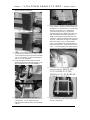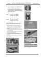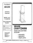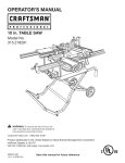
1
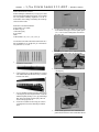
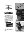
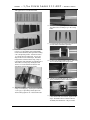
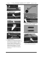
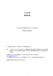
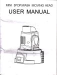
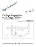
Lanier R/C
rd
1/3 Scale
LA SE R 200
A R F
lm ost
eady to
ly
W A R N IN G !TH IS IS N O T A TO Y !
TH IS IS N O T A BEG IN N ER S A IR PLA N E
T his R /C kit and the m odelyou w illbuild from it is not a toy! It is capable of serious bodily harm and property
dam age. It is your responsibility,and yours alone -to build thiskitcorrectly,properly installallR/C com ponentsand
flying gear (engine,tank,radio,pushrods,etc.and to test the m odel and fly it only w ith experienced,com petent help,
using com m onsense and in accordance w ith allsafety standards as setforth in the A cadem y of M odelA eronautics Safety
Code. Itis suggested thatyou join the A M A and becom e properly insured before attem pting to fly this m odel. Ifyou are
juststarting R/C m odeling, consult your local hobby dealer or w rite to the A cadem y of M odel A eronautics to find an
experienced instructorin yourarea. W rite to: A cadem y ofM odelA eronautics,5151 M em orialD r.M uncie,IN 47302
LIM ITED W A RRA N TY
Lanier R/C is proud of the care and attention thatgoes into the m anufacture of parts for its m odelkits. The com pany
w arrants thatfor a period of 30 days,itw illreplace,atthe buyers request,any partor m aterialshow n to the com pany’s
satisfaction to have been defective in w orkm anship orm aterialatthe tim e ofpurchase.
N o other w arranty of any kind,expressed or im plied,is m ade w ith respectto the m erchandise sold by the com pany. The
buyer acknow ledges and understands that he is purchasing only a com ponent kit from which the buyer w ill him self
constructa finished flying m odelairplane. The com pany is neitherthe m anufacturerofsuch a flying m odelairplane,nora
sellerofit. The buyerhereby assum es the risk and allliability forpersonalorproperty dam age orinjury arising outofthe
buyers use ofthe com ponents orthe finished flying m odelairplane,w heneverany such dam age orinjury shalloccur.
A ny action broughtforth againstthe com pany,based on the breach of the contractof sale to the buyer,or on any alleged
w arranty thereunder,m ust be brought w ithin one year of the date of such sale,or there after be barred. This one-year
lim itation is im posed by agreem entofthe parties as perm itted by the law s ofthe state ofG eorgia.
© 2002 LanierR/C
LANIER
– 1/3 rd S cale Laser 200 A R F - INSTRU CTIO NS
BUILDING INSTRUCTIO NS
Beforestarting to build this kit,w e urge you to read
through these instructionsthoroughly. They contain
som e im portant building sequences as w ell as
instructions and w arnings concerning the assem bly
and use ofthe m odel.
BUILDING SUPPLIES NEEDED
H obby knife w /#11 blade
M edium Zap CA
30 M inute Z-poxy
W ire cutters
Pliers
D rillw ith bits:1/32”,1/16”,1/8”,5/32”,¼”
5. M ark the location ofthe aileron servo plate rails
on the inside ofthe plyw ood servo plate (aprox.
3/8”). Rem ove the covering from the hole for
the servo arm .
See the listatthe end ofthe instruction book for a
list of additionalR /C equipm ent you w illneed to
com plete the 1/3rd Laser.
6. Position youraileron servos and the hardw ood
blocks on the plates and m ark the position.
1.
Locate (10)hinge points.
7. G lue the blocksin place on the platesw ith 30
m inute epoxy.
2. U se the picture asa guide to find the (5)holesin
each aileron and each side ofthe w ing. Testfita
hinge in each hole.
3. Puta smalldrop ofoilon each hinge,then use 30
m inute epoxy on each hinge and hole. Pressthe
aileronsin place,leaving a 1/32” gap atthe hinge
line,then w ipe offany excess epoxy offw ith
alcoholand a papertow el.
4. A tthe tw o locations on the w ing,rem ove the
covering from the hole to installyouraileron
servo.
8. W hen cured,replace the servo and drill1/32”
pilotholesforthe servo screw sincluded w ith the
© 2002 LanierR/C
Page-2
LANIER
– 1/3 rd S cale Laser 200 A R F - INSTRU CTIO NS
radio. Centerthe servo by hooking itup to the
properchannelofyourradio and centering the
trim tabs.
9. Installyourservo horn so thatitisprotruding the
hole ofthe plate and installthe servo horn screw .
12. Locate the Sullivan aileron hardw are,(2)2 7/8”long
4-40 rods,(4)clevis,(2)couplers,(2)m achined
nuts,and (2)8-32 long” screw s. Trim and thread
the rods as needed. Installa clevison the end of
each rod.
10. U se a piece ofm usic w ire orw ooden dow elto
help feed the servo w ires through thewing.You
w illneed to add extensions to the aileron servo
w ires to reach into the fuselage.
11. Fasten the servo plate to the hardw ood plate rails
in the w ing w ith (4)#4 x”½ screw s (dubro
#382)
13. Installa (4)arm servo w heelon the servo
tem porarily,m aking sure itisparallelto the
w ing.Locate the hard pointsin the ailerons,and
pierce the covering w ith a sharp hobby blade.
Installthe (2)aileron controlhorn screw sfrom
the top ofthe w ing,dow n through the aileron.
Secure the boltw ith the m achined nut,and
thread lock. Installthe (2)couplers on the
controlhorn bolts untilthe threads justshow
from the tops. H ook the links to the aileron
couplersand lay the rodsacrossthe servo arm .
14. Installthe tw o clevis on the ends ofthe 4-40rod.
A lign the aileron on the w ing and hold in
position w ith a sm allpiece oftape. A djustthe
clevis to the properlength,then installon the
servo and coupler. U se red thread lock w hen
adjusted,then installthe clevis keeper.
© 2002 LanierR/C
Page-3
LANIER
– 1/3 rd S cale Laser 200 A R F - INSTRU CTIO NS
15. U sing a sharp hobby blade,cutthe covering
aw ay from the w ing tube and locating pin holes.
Y ou m ay w antto sealthe covering dow n w ith
CA ora sealing iron.
16. Testfitthe w ing tube through the fuselage. U se
a rulerto help centerthe tube in the fuse,then
m ark the alignm entw ith a perm anentm arker.
17. Tem porarily m ountthe w ing on the w ing tube,
sliding the dow els in the locatorholes. Be
carefulto keep the tube centered in the fuse.
19. U se a 6-32 tap to thread the holes in the tube.
20. Countersink the hard points 1/8” deep w ith a
1/4”drillbit. W ork carefully to keep the w ood
from splitting.
21. Testfitthe boltsin the holes. Putthread lock on
one boltand coverthe bolthole w ith 3m vinyl
tape. Leave thisboltin place perm anently.
22. W hen ready forflying,put3M clearvinyltape
overthe otherbolt.
18. Locate the (2)6-32 x 1” bolts. W ith the w ings
tightagainstthe fuse,D rill(2)0.1” holes
through the alum inum tube.
© 2002 LanierR/C
Page-4
LANIER
– 1/3 rd S cale Laser 200 A R F - INSTRU CTIO NS
23. Tem porarily installthe horizontalstabilizer.
Y ou m ay need to sand the opening slightly to be
able to slide itin,butbe carefulto keep the
stabilizeraligned parallelto the w ing.
24. A lign the stabilizerby m easuring from each side
to the centerand equalizing the distance,then
m easure from the stabilizertips to the trailing
edge ofthe w ing and seteach side equal.
25. M ark the jointw ith a feltm arkeron the top and
bottom . Slide the stabilizerback out,then
rem ove the covering from inside the m arks,1/8”
inside the linesyou m arked. U se a sharp hobby
blade to cutthe covering. Be very carefulto
notcutthe balsa under the covering.
Slide the stabilizerback in the fuselage justuntil
the exposed balsa isatthe tailopening. A pply a
thin coatof30 m inute epoxy to the exposed
balsa,then slide the stabilizerback in the tail.
Re-align the stabilizerw ith the m arksyou m ade
earlierand double check yourm easurem ents to
the w ing from yourbuilding surface. W ipe off
any excessglue w ith alcoholand a papertow el.
Letsetuntilcured.
26. Tem porarily installthe verticalstabilizerin the
horizontalslotatthe rearofthe fuse. M ark the
jointw ith a felttip m arker. M ake sure the
stabilizerisaligned at90° to the horizontal
stabilizer,then rem ove the stabilizerand rem ove
the covering as w as done w ith the horizontal
stabilizer.
27. Testfitthe sm allhorizontalstab spacerblock in
the space behind the stab.
28. Spread som e epoxy on the spacerblock and
insertin the rearofthe fuse. Proceed to the
nextstep before the epoxy cures.
29. Putsom e 30 m inute epoxy in the slotand on the
exposed balsa on the stabilizer,then slide
together. Check thatitisat90° to the horizontal
stabilizer. W ipe offany excessglue w ith alcohol
© 2002 LanierR/C
Page-5
LANIER
– 1/3 rd S cale Laser 200 A R F - INSTRU CTIO NS
and a papertow el. Letsetuntilcured.
32. Locate the servo openings on the sides ofthe
fuse and cutthe covering aw ay w ith a sharp
knife.
33. Locate the tailservo ply platesand position them
on both sides ofthe servo openings.
30. Locate the (4)hinge holesin each ofthe elevator
halves,(5)in the rudder,and corresponding
holes on the stabilizers,then open the covering
w ith a sharp hobby blade. Testfitone ofthe
(13)hingesin each ofthe holes. Puta sm all
drop ofoilon each ofthe hinges. Installthe
hinges in the controlsurfaces only,using 30
m inute epoxy,then align them by pressing onto a
flatsurface. Clean up any excess glue w ith
alcohol. D o notinstallthe surfaceson the
stabilizersuntilthe epoxy hascured.
34. M ark the ply plate positionsw ith a m arker,then
rem ove the covering w ith a sharp knife.
35. G lue the ply platesin place w ith 30 m inute
epoxy,and clam p in place untilcured.
31. Installthe surfaces on the rearofthe fuselage
using 30 m inute epoxy. Pressin place and leave
a 1/32” gap. W ipe offany excess glue w ith
alcoholand a papertow el. Letsetuntilcured.
36. Locate yourtailservosand install24” extension
w ires on the leads (secure them togetherw ith
tape). Installthe servos w ith the hardw are
included,then centerthem w ith yourradio.
© 2002 LanierR/C
Page-6
LANIER
– 1/3 rd S cale Laser 200 A R F - INSTRU CTIO NS
37. U se a straightedge to align the elevatorand
ruddercontrolhorns location.
42. Locate the tailw heelbracketand parts.
38. Installthe hornson the elevatorhalvesw ith (4)
4-40 screw s in each horn going through to the
backing plate.
43. Fasten the tailbracketatthe rearofthe fuse w ith
tw o #6 ½screw s. D rilltw o 3/32” pilotholes
before installing.Installso the angle isaligned
w ith the edge ofthe verticalstabilizer.
39. Installthe rudderhorns by securing them w ith
(4)4-40 screw sand (4)nylon lock nuts.
40. Installyourservo arm s (D ubro heavy duty,not
included)on the servos.
41. Trialfitthe 4-40 rods and clevis on the servos
and horns,the 5 1/2” rodsare fortheelevatorhalves,
the 10” rodsare forthe rudder. Tw o solder
clevis are used on the rudderrods. Trim therods
to length as needed. W hen the lengths are
determ ined and allsurfacesare centered,lock the
clevison the rod w ith locktite. (Y ou can also
solder one clevisin position ifyou w antto be
very secure ) A lso installthe cleviskeeperson
the clevis pins.
.
44. Locate the springs forthe tail,and prepare the
ends by bending a loop on each end.
45. Installa spring on each side ofthe rudder.
Shorten the springsifneeded to puteven tension
on the arm s and keep the axle centered.
© 2002 LanierR/C
Page-7
LANIER
– 1/3 rd S cale Laser 200 A R F - INSTRU CTIO NS
46. Installthe tailw heelon the axle,then secure
w ith the sm allw heelcollarand setscrew . U se
som e thread lock on the screw .
47. Locate the hard pointsin the tailsurfacesforthe
tailbrace w ires. Pierce the covering w ith a sharp
blade. Puta slightbend in (12)ofthe tailw ire
brackets,then installthem in the horizontaland
verticalstabilizers as show n,w ith a bracketon
both sides ofthe surfaces. U se a 4-40 screw and
lock nuton each bracket.
49. M ark the length ofthe rods about¼” pastthe
largesthole in the horizontalbraces,then trim .
Bend at90 degrees,then insertin the hole.
Secure w ith an L connector. A djustatthe clevis
end,butdon’tw arp the horizontalsurface.
50. Installthe tailbrace bracketusing the rear#6
screw . A ssem ble the other(4)tailbrace w ires
the sam e as the top,then secure w ith the L
connectors.
51. M ake sure each clevis gets a keeperinstalled.
48. Installa 2-56 clevis on the ends ofthe (8)2-56
threaded rods,then install(4)rodsin the m iddle
hole ofthe verticalbraces.
52. Locate the (4)4 x 20m m screw s forinstallation
ofthe cow l.(2)are round head screw s,(2)are
flathead screw s.
© 2002 LanierR/C
Page-8
LANIER
– 1/3 rd S cale Laser 200 A R F - INSTRU CTIO NS
53. Placethe fiberglass cow lon the fuse and fasten
w ith the 4m m screw sthrough the holes. The flat
head screw s go in the top end ofthe cow l.
M easure from the engine crank hole to the first
form ersurface w ith a ruler. W rite dow n the
length.
54. N ow m easure the length ofyourm otorw ith the
m otorm ountinstalled,from the frontofthe prop
backing plate to the rearofthe m ount. Subtract
¼” from thislength (forprop clearance ofthe
cow l).
56. G lue the firew allin the fuse atthe m arksyou just
scribed. U se 30 m inute epoxy and clam p in
place untilcured.
57. A djustthe length ofthe ¼ ply low erso the
beveled edge is even w ith the frontofthe
firew all.Rem ove the covering from the bottom
ofthe firew allform ersto allow glue to penetrate,
and epoxy the plate in place. Clam p in place
untilcured.
58. W hen allis cured,cutthe fuse sides flush w ith
the firew all.
55. Subtractthe m otorm easurem entfrom the cow l
m easurem ent. Thisw illbe the distance the
firew allneedsto be from the firstform er. U se a
rulerand straightedge to m ake a 90 degree line
on the fuse sides w here the firew allshould be
installed.
59. A djustthe length ofthe engine box doublers,
then glue in place w ith w hite glue orepoxy.
Clam p untilset.
© 2002 LanierR/C
Page-9
LANIER
– 1/3 rd S cale Laser 200 A R F - INSTRU CTIO NS
64. Centeryourengine m ounton these lines,then
m ark the holeson the firew all.
60. G lue the balsa triangle stock in place w ith CA .
65. D rillthe holesfor10-32 bolts and tem porarily
m ountthe engine on the firew allw ith 10-32x
1”-1/4 bolts,#10 w ashers,and blind nuts .
61. U se a rulerto find the verticalcenterofthe
firew alland m ark a straightline.
62. M ake a second m ark 1/8” to the right(w hile
looking atthe firew allfrom the front)ofthe
centerm ark,and m ake a second m ark,then draw
a line perpendicularto the firstline.
63. M easure dow n from the top ofthe firew all21/4”” and m ark a horizontalline.
66. M easure the distance from the firew allto the
frontofthe prop back plate and com pare to the
m easurem entyou calculated earlier. Y ou should
have a m inim um of1/8” clearance from the back
ofthe prop to the frontofthe cow ling. If
needed,use som e scrap plyw ood spacers to
space the engine forw ard.
67. Place tw o #8 w ashers betw een the firew alland
engine m ounton both rightside engine m ounting
bolts(facing the firew all)to give theengineright
thrust.
68. W hen the engine isaligned properly,installthe
10-32 nylon lock nuts in place inside the
© 2002 LanierR/C
Page-10
LANIER
– 1/3 rd S cale Laser 200 A R F - INSTRU CTIO NS
firew all,behind the blind nuts.
72. M ake sure yourcarburetorand throttle servo are
atlow position. Reverse yourservo ifnecessary.
Thread the 2-56 clevison the 12” rod,then snap
the clevis on the servo arm . Installan EZ
connectorin the hole on yourcarburetor
approxim ately the sam e length ofthe servo arm .
Trim the throttle controlrod to approxim ate
length,then insertthrough the hole in the EZ
connector. Tighten the connectorenough to test
the throw ofthe servo and adjustas needed to
allow form axim um throw ,butnotbind the
servo. W hen satisfied,trim the controlrod to ¼”
pastthe EZ connector. Installthe servo horn
screw . W hen everything is fit,then fuelproof
the firew allw ith polyurethane orthinned epoxy.
69. D rill(5)3/32” holeson each side ofthe firew all,
through the fuse sides about1” deep. Press a
w ood toothpick into the hole,then cutoffflush
w ith som e w ire snips. A pply severaldrops of
thin CA on each toothpick.
70. M ark on the firew allthe location w here the
throttle controlrod should pass through. D rill
the m arked hole w ith a 1/8”aircraftdrillbit.
73. Testfitthe cow loverthe engine to see w hat
needs to be relieved. SH A V E TH E
TO P C O R N ER S O F TH E
FIR EW A LL TO ELIM IN A TE
R U BBIN G O N C O W L.
74. U se m asking tape to m ark the areasthatneed to
71. U sing yourservo as a guide,glue the tw o
be rem oved forthe head ofthe engine to clear
hardw ood servo blocksto the fuse side using 30
the cow l,then testfit.
m inute epoxy. Cuta sm allpiece ofbalsa
triangle stock to filletthe servo rails and fasten
w ith CA .
© 2002 LanierR/C
Page-11
LANIER
– 1/3 rd S cale Laser 200 A R F - INSTRU CTIO NS
80. Centerthe w heelpantplate inside the pant,then
fasten w ith 30 m inute epoxy.
75. Y ou w illneed to relieve m ore ofthe cow l,
depending on the m uffleryou decide to use.
76. Installthe landing gearon the bottom ofthe fuse
w ith the included 4m m screw sand w ashers.
81. Secure the axle supportplate on the opposite
side,keeping the w heelpantlevel.
77. Position the gearfairing on the gear,then glue in
place w ith goop. Clam p in place untildry.
82. Press the 4-40 blind nutinto the plate using a
sm allclam p orlarge pliers.
78. Locate the position ofthe axle hole in the w heel
pants using the 4” w heelas a guide.
79. M ark the size ofthe axle hole w ith the plyw ood
w heelpantplate,then drillw ith a drem el
grinding bit.
© 2002 LanierR/C
Page-12
LANIER
– 1/3 rd S cale Laser 200 A R F - INSTRU CTIO NS
83. Boltthe axle through the landing gearw ith the
axlespointing out. U se thread lock on the bolt.
84. Installthe tip ofthe axle through the pant,then a
collar,the 4”w heeland collar,then slide the
assem bly allthe w ay dow n the axle.Tighten the
w heelcollarso thatitdoes notbind the w heel
againstthe w heel.
85. A lign each w heelpantto the fuse so thatitis
levelw ith the thrustline and the reardoes not
drag the ground,and keep the pairequal. D rilla
1/8” hole in the landing gearto align w ith the 440 blind nut,then installthe boltand w asher.
USE LOCKTITE ON THIS BOLT!
86. Locate the fueltank and rem ove allthe
com ponents forassem bly. Check the inside of
the tank forany dustorplastic shavings. Blow
outifneeded. Ifyou are going to use a glow
engine,you need to replace the stopperand line
w ith silicone parts.
87. Bend the m etalfueltubesso the ventline fits
into the button on the top,and the pickup lineis
angled tow ard the bottom justa few degrees,
then insertin the fuelstopper. Insertthe clunk
on the end ofthe silicone fueltubing and cutto
required length thatallow itto m ove freely atthe
end ofthe tank. Insertthe nutand boltin the
stopper,then installthe stopperin the tank and
tighten.
© 2002 LanierR/C
Page-13
LANIER
– 1/3 rd S cale Laser 200 A R F - INSTRU CTIO NS
88. Secure the tank in the fuse w ith cable ties
through holes in the fuse floor.
89. Installyourfuelline on the end ofthe tank lines
to the m ufflerpressure and carburetorfittings.
M ake sure to allow enough extra line to the
needle valve line to give accessforfilling.
90. Locate the holes forthe ccockpitscrew s and
rem ove any covering w ith a sharp knife.
93. N ow isthe tim e to installany cockpitdetails,
such as dashboards orpilots (N O T
IN CLU D ED ). Secure them firm ly in the cockpit
w ith epoxy.
94. Installthe canopy on the fuselage w ith epoxyor
“goop”. H old in place w ith tape untilcured.
91. Testfitthe cockpitcoverand 4 m m flathead
screw s.
95. W ith yourengine fully setup,now reinstallthe
cow ling and fasten in place w ith the cow l
screw s. Installyourprop and 4” spinner. (W e
recom m end Tru Turn spinners.)
92. Trim the clearplastic canopy ¼” from the
scribed line,then testfiton the fuselage. Trim if
needed.W ash the canopy outw ith coolw ater
and dish detergent,then dry w ith a papertow el.
96. Tem porarily place yourbattery and receiverin
the fuse,then installthe w ing. Y ou w antthe
plane to balance on the w ing tube center.
© 2002 LanierR/C
Page-14
LANIER
– 1/3 rd S cale Laser 200 A R F - INSTRU CTIO NS
97. M ove yourbattery fororaftasneeded to achieve
a balance. Ifneeded,putthe battery in the
forw ard com partm ent,behind the firew all.
W hen the properradio gearposition is found,
w rap the gearw ith foam and secure in place w ith
V elcro orrubberbands.
Landing gearcuffs
CO NTRO L TH RO W S
Rudder:
Low rate – 1-1/2” each w ay
H igh rate -allyou can get
Elevator:
Low rate -1” each w ay
H igh rate – allyou can get
A ilerons: Low rate – 1/2” each w ay
H igh rate – allyou can get
Fiberglasscow l
PRE-FLIG H T NO TES
Before the firstflightyou should double check a few
things to ensure a long life foryournew plane.
1. Balance the Laserw ith the fueltank em pty.
A djustasneeded foryourparticularflying style,
butstartw ith the CG forw ard forthe firstfew
flights.
2. Check the controlsurface throw stw ice. Y ou m ay
w antto change them later,butuse the suggestions
as a starting point.
3. Break in the engine and testrun it. H ave itready
before you head to the field.
4. Range check the radio w ith the engine running to
m ake sure there are no interm ittentradio
problem s.
Double check thatallthe hardw are,nuts,bolts,and
hinges are tight.
INCLUDED M ATERIALS
Clearcanopy
Fuselage and cockpithatch
W ood bag and firew all
H orizontalStab and elevatorhalves
A lum inum w ing tube
Fiberglass w heelpants
© 2002 LanierR/C
Page-15
LANIER
– 1/3 rd S cale Laser 200 A R F - INSTRU CTIO NS
Cowl
2
2
1
2
4 x 20m m round head screw s
4 x 20m m flathead screw
24 oz fueltank
Largenylon cable ties
Engine m ount
4 10-32 x 1-1/2 cap screw
8 #10 w asher
4 10-32 nylon lock nuts
1 12"2-56 rod
1 2-56 clevis
1 ez connector
W ing halves
A ilerons
Landing gear
4
4 x 22m m round head screw s
4
4m m w asher
2
4-40 blind nuts
2
248 3/16 axle
2
4" w heel
2
4-40 x 1/2 cap screw
2
#4 w asher
1
A lum inum landing gear
Rudderand V erticalstab
Canopy
4
3 x 20m m flathead screw
H ARDW ARE LIST
W ings
2 H D adjustable controlhorn
2 2& 7/8" 4-40 threaded rods
2 6-32 x 1" cap screw
10 large hinge points
8 #4 x 1/2 sheetm etalscrew
4 4-40 clevis
Tail
13
4
12
4
2
2
6
2
2
1
1
2
12
8
8
8
1
6
6
large hinge points
large tstyle horns (included)
4-40 x 3/4 cap screw
4-40 nylon lock nuts
10" 4-40 threaded rod
5 1/2" 4-40 threaded rod
4-40 clevis
Solderclevis
#6 x 3/4" pan head screw
1-1/4 tailw heel
Ohio superstartailw heelbraket
1/8" w heelcollars
tailbrace brackets
18"2-56 threaded one end rod
2-56 clevis
nylon L connectors
2"x3/4"alum inum plate w ith 5 holes,
#6 size in center,3/32 in 4 corners
4-40 x 3/4 cap screw
4-40 nylon lock nuts
ADDITIO NAL EQ UIPM ENT NEEDED TO
CO M PLETE YO UR 1/3rd LASER ARF
G eneral
3.2– 4.2 2 stroke R/C engine and m uffler
G asfuelline
M inim um of4 chan.radio setreq.with (7) servos
30 m inute Z-poxy
M edium Zap CA (green)
Thin Zap CA (pink)
Zap a dap goop
(1)radio foam
Tru Turn 4” spinner
6/32 tap
3M vinyltape
W illiam sBro.Pilotfigure
© 2002 LanierR/C
Page-16