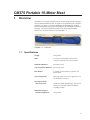
1
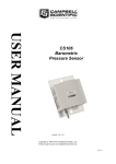
INSTRUCTION MANUAL CM375 Portable 10-Meter Mast Revision: 10/14 C o p y r i g h t © 2 0 0 9 - 2 0 1 4 C a m p b e l l S c i e n t i f i c , I n c . Precautions DANGER — MANY HAZARDS ARE ASSOCIATED WITH INSTALLING, USING, MAINTAINING, AND WORKING ON OR AROUND TRIPODS, TOWERS, AND ANY ATTACHMENTS TO TRIPODS AND TOWERS SUCH AS SENSORS, CROSSARMS, ENCLOSURES, ANTENNAS, ETC. FAILURE TO PROPERLY AND COMPLETELY ASSEMBLE, INSTALL, OPERATE, USE, AND MAINTAIN TRIPODS, TOWERS, AND ATTACHMENTS, AND FAILURE TO HEED WARNINGS, INCREASES THE RISK OF DEATH, ACCIDENT, SERIOUS INJURY, PROPERTY DAMAGE, AND PRODUCT FAILURE. TAKE ALL REASONABLE PRECAUTIONS TO AVOID THESE HAZARDS. CHECK WITH YOUR ORGANIZATION'S SAFETY COORDINATOR (OR POLICY) FOR PROCEDURES AND REQUIRED PROTECTIVE EQUIPMENT PRIOR TO PERFORMING ANY WORK. Use tripods, towers, and attachments to tripods and towers only for purposes for which they are designed. Do not exceed design limits. Be familiar and comply with all instructions provided in product manuals. Manuals are available at www.campbellsci.com or by telephoning (435) 227-9000 (USA). You are responsible for conformance with governing codes and regulations, including safety regulations, and the integrity and location of structures or land to which towers, tripods, and any attachments are attached. Installation sites should be evaluated and approved by a qualified engineer. If questions or concerns arise regarding installation, use, or maintenance of tripods, towers, attachments, or electrical connections, consult with a licensed and qualified engineer or electrician. General x Prior to performing site or installation work, obtain required approvals and permits. Comply with all governing structure-height regulations, such as those of the FAA in the USA. x Use only qualified personnel for installation, use, and maintenance of tripods and towers, and any attachments to tripods and towers. The use of licensed and qualified contractors is highly recommended. x Read all applicable instructions carefully and understand procedures thoroughly before beginning work. x Wear a hardhat and eye protection, and take other appropriate safety precautions while working on or around tripods and towers. x Do not climb tripods or towers at any time, and prohibit climbing by other persons. Take reasonable precautions to secure tripod and tower sites from trespassers. x Use only manufacturer recommended parts, materials, and tools. Utility and Electrical x You can be killed or sustain serious bodily injury if the tripod, tower, or attachments you are installing, constructing, using, or maintaining, or a tool, stake, or anchor, come in contact with overhead or underground utility lines. x Maintain a distance of at least one-and-one-half times structure height, 20 feet, or the distance required by applicable law, whichever is greater, between overhead utility lines and the structure (tripod, tower, attachments, or tools). x Prior to performing site or installation work, inform all utility companies and have all underground utilities marked. x Comply with all electrical codes. Electrical equipment and related grounding devices should be installed by a licensed and qualified electrician. Elevated Work and Weather x Exercise extreme caution when performing elevated work. x Use appropriate equipment and safety practices. x During installation and maintenance, keep tower and tripod sites clear of un-trained or nonessential personnel. Take precautions to prevent elevated tools and objects from dropping. x Do not perform any work in inclement weather, including wind, rain, snow, lightning, etc. Maintenance x Periodically (at least yearly) check for wear and damage, including corrosion, stress cracks, frayed cables, loose cable clamps, cable tightness, etc. and take necessary corrective actions. x Periodically (at least yearly) check electrical ground connections. WHILE EVERY ATTEMPT IS MADE TO EMBODY THE HIGHEST DEGREE OF SAFETY IN ALL CAMPBELL SCIENTIFIC PRODUCTS, THE CUSTOMER ASSUMES ALL RISK FROM ANY INJURY RESULTING FROM IMPROPER INSTALLATION, USE, OR MAINTENANCE OF TRIPODS, TOWERS, OR ATTACHMENTS TO TRIPODS AND TOWERS SUCH AS SENSORS, CROSSARMS, ENCLOSURES, ANTENNAS, ETC. PLEASE READ FIRST About this manual Please note that this manual was originally produced by Campbell Scientific Inc. (CSI) primarily for the US market. Some spellings, weights and measures may reflect this origin. Some useful conversion factors: Area: Length: Mass: Pressure: Volume: 1 in2 (square inch) = 645 mm2 1 in. (inch) = 25.4 mm 1 ft (foot) = 304.8 mm 1 yard = 0.914 m 1 mile = 1.609 km 1 oz. (ounce) = 28.35 g 1 lb (pound weight) = 0.454 kg 1 psi (lb/in2) = 68.95 mb 1 US gallon = 3.785 litres In addition, part ordering numbers may vary. For example, the CABLE5CBL is a CSI part number and known as a FIN5COND at Campbell Scientific Canada (CSC). CSC Technical Support will be pleased to assist with any questions. About sensor wiring Please note that certain sensor configurations may require a user supplied jumper wire. It is recommended to review the sensor configuration requirements for your application and supply the jumper wire is necessary. Table of Contents PDF viewers: These page numbers refer to the printed version of this document. Use the PDF reader bookmarks tab for links to specific sections. 1. Overview ...................................................................... 1 1.1 1.2 Specifications ....................................................................................... 1 Guy Duckbill Anchor Kits ................................................................... 2 2. Tools List (for tripod, mast, enclosures, and crossarms) ................................................................ 3 3. CM375 Installation ...................................................... 3 3.1 3.2 3.3 3.4 3.5 Site Selection ....................................................................................... 3 Assembling Mast Sections ................................................................... 4 Lightning Rod Assembly and Mounting Instrumentation .................. 12 Anchor Installation ............................................................................. 13 Raise, Plumb Mast and Final Cable Tensioning ................................ 18 4. Maintenance .............................................................. 20 Figures 1-1. 3-1. 3-2. 3-3. 3-4. 3-5. 3-6. 3-7. 3-8. 3-9. 3-10. 3-11. 3-12. 3-13. 3-14. 3-15. 3-16. 3-17. 3-18. 3-19. 3-20. 3-21. 3-22. 3-23. 3-24. 3-25. 21720 tote............................................................................................. 1 Assembled CM375 ............................................................................... 3 CM375 in opened tote .......................................................................... 4 Mast base, sections, and lightning rod kit ............................................ 4 Mast Section 1 oriented on base........................................................... 5 Spike installation .................................................................................. 6 Coupler installed in top of mast Section 1 ........................................... 6 Bag containing hardware ..................................................................... 7 Mast Section 2 and mast Section 3 ...................................................... 7 Guy ring, mast Section 2 and mast Section 3 ....................................... 8 21663 bottom guy kit ........................................................................... 8 Guy cable inserted into guy ring .......................................................... 9 Mast Section 3 and guy ring/collar assembly ....................................... 9 Mast Section 4 ready to be installed in mast Section 3 ...................... 10 Mast Section 5.................................................................................... 10 21661 guy kit ..................................................................................... 11 Mast Section 5 and guy ring/collar assembly ..................................... 11 Mast Section 6.................................................................................... 12 Lightning rod assembly ...................................................................... 12 Installed lightning rod ........................................................................ 13 Tape measure in slot for South anchor ............................................... 13 19282 duckbill anchor and cable assembly (left). The 25699 has a threaded rod instead of the cable. The drive rod (right) is used for both the 19282 and 25699. ........................................................ 14 Anchor driven into ground at 45° angle ............................................. 14 Locking anchor .................................................................................. 15 Tape measure in slot for Northeast anchor......................................... 15 Turnbuckle fastened to guy cable and anchor .................................... 16 i Table of Contents 3-26. 3-27. 3-28. 3-29. 3-30. 3-31. 3-32. Top and bottom guy cables fastened to an anchor ............................. 16 Rope ratchet assists assembly............................................................ 17 Adjusting cable through wedge clamp .............................................. 17 Raising the mast ................................................................................ 18 Post level ensures vertical mast ......................................................... 18 Adjusting turnbuckles ....................................................................... 19 Guy cables with 100 lb of tension ..................................................... 19 ii CM375 Portable 10-Meter Mast 1. Overview The CM375 is a corrosion-resistant 10 m (30 ft) mast for applications requiring a tall yet portable instrument mount. It consists of six galvanized pipes, a stainlesssteel base, guy cables, 1 m crossarm and mount, and grounding kit. Duckbill anchor kits (required) and a guy-wire tensioning kit (recommended) are ordered separately. All of the components fit inside a 2 m (80 in) bag allowing the CM375 to be carried from site to site (see FIGURE 1-1). FIGURE 1-1. 21720 tote 1.1 Specifications Weight: 30 kg (66 lb) Mast: 9.2 m (30 ft) total length; consists of five 1.82 m (6 ft) and one 1 m (39 in) sections Main Mast Diameter: 48.26 mm (1.9 in) Top Section Mast Diameter: 44.2 mm (1.74 in) Base Radius: 6 m (20 ft) to each of three guy points, 120 degrees apart Guy Configuration: Three guy cables at two levels; guyed at 3.6 m (12 ft) and at 7.2 m (24 ft) Recommended Guy Wire Pretension: Maximum Weight of Mounted Equipment: 100 lb each; check and adjust guy wire tension at least once a month, and after wind gusts exceeding 50 mph 34 kg (75 lb) 1 CM375 Portable 10-Meter Mast Maximum Allowable Wind Gust i: 136 kmh–1 (85 mph) The wind gust value assumes: x Proper installation x Proper anchoring: o Adequate soil (guy anchors/base support) o Guy anchors at 20-ft from base with 120 degrees of separation o Proper guy tension (100 lb each) x No ice buildup x Standard air quality or wind assessment configuration (see Table below) 1.2 Guy Duckbill Anchor Kits A choice of duckbill anchor kits is offered for the CM375. The 19282 Guy Duckbill Standard Anchor Kit is adequate for most sandy and loamy soils. Clay soils and other soils with higher corrosive properties will require the 25699 Guy Duckbill Heavy Duty Anchor Kit. These corrosive soils, also known as aggressive soils, have one or more of the following properties: x x x x x High electrical conductivity (>0.33 dS m–1) High acidity (pH <5) High chloride concentration (>1000 ppm) High sulfate concentration (>500 ppm) Poor aeration Both the 19282 and 25699 have one drive rod. The 19282 also has three duckbill anchors with a cable attached to each of them; at the end of the cable is a loop for connecting the guy wires. The 25699 has a threaded rod attached to each of the three duckbill anchors instead of the cable; at the end of the threaded rod is a metal ring for connecting the guy wires. i The amount of wind gust that this mount can withstand is affected by quality of anchoring and installation, guy wire tension, soil type, guy angle, and the number, type, and location of instruments fastened to the CM375. 2 CM375 Portable 10-Meter Mast 2. Tools List (for tripod, mast, enclosures, and crossarms) 1/2-in. and 7/16-in. open end wrenches adjustable wrench Phillips head screw drivers (medium, small) Straight bit screwdrivers (large, medium) 12-in. torpedo level side-cut pliers pencil tape measure compass and site declination angle shovel sledge hammer (for driving ground rod and stakes) step ladder 3. CM375 Installation 3.1 Site Selection Select a site free from overhead power lines, and 30 m (100 ft) in any direction from trees, buildings, and other obstructions (see FIGURE 3-1). FIGURE 3-1. Assembled CM375 3 CM375 Portable 10-Meter Mast 3.2 Assembling Mast Sections Step 1: Remove mast sections and other bundled hardware from tote; unzip and loosen straps (see FIGURE 3-2). NOTE Sections are numbered for sequential assembly (see FIGURE 3-3). FIGURE 3-2. CM375 in opened tote Base FIGURE 3-3. Mast base, sections, and lightning rod kit 4 CM375 Portable 10-Meter Mast Step 2: Place Section 1 at deployment location with base oriented, as shown in FIGURE 3-4 and mast pointing NORTH. NOTE A compass is included in the optional “Tensioning Kit” for your use. NORTH FIGURE 3-4. Mast Section 1 oriented on base Step 3: Use spikes provided (3 each) to anchor base to site (see FIGURE 3-5). WARNING Always maintain a safe distance between the mast and any overhead power lines. Contact local utilities prior to assembling the mast to locate any buried utility lines in the area the mast is to be installed. 5 CM375 Portable 10-Meter Mast NORTH Spikes FIGURE 3-5. Spike installation Step 4: Insert the Section 2 coupler into the top of Section 1 (see FIGURE 3-6). FIGURE 3-6. Coupler installed in top of mast Section 1 6 CM375 Portable 10-Meter Mast Step 5: Secure joint with 2 flat washers, 2 lock washers and 2 bolts from the hardware bag (see FIGURE 3-7). FIGURE 3-7. Bag containing hardware Step 6: Assemble Section 3 to the top of Section 2 (see FIGURE 3-8). NOTE The BLACK tape around Section 2 is a reference (11 foot level) for optional sensor mounts. Section 2 Collar FIGURE 3-8. Mast Section 2 and mast Section 3 Step 7: Remove the collars from Section 3 and place next to the mounting holes in Section 2 (see FIGURE 3-8 and FIGURE 3-9). 7 CM375 Portable 10-Meter Mast Collar Guy Ring Section 2 Section 3 Collar FIGURE 3-9. Guy ring, mast Section 2 and mast Section 3 Step 8: Remove guy ring from bottom guy kit, pn 21663 (see FIGURE 3-9 and FIGURE 3-10). FIGURE 3-10. 21663 bottom guy kit 8 CM375 Portable 10-Meter Mast Step 9: Place ball end of each guy cable into its slot in the guy ring and place guy ring onto coupler of Section 3 (see FIGURE 3-11). FIGURE 3-11. Guy cable inserted into guy ring NOTE Only one of the three cable ends is shown. Step 10: Slide coupler into Section 2 mast and assemble collars, as shown in FIGURE 3-12. FIGURE 3-12. Mast Section 3 and guy ring/collar assembly 9 CM375 Portable 10-Meter Mast Step 11: Slide coupler end of Section 4 into the top of Section 3, and secure with remaining components from hardware bag (see FIGURE 3-13). Section 3 Coupler FIGURE 3-13. Mast Section 4 ready to be installed in mast Section 3 Step 12: Remove collars from Section 5 (see FIGURE 3-14). Collar Collar FIGURE 3-14. Mast Section 5 10 CM375 Portable 10-Meter Mast Step 13: Remove the guy collar from the 21661 guy kit (FIGURE 3-15). FIGURE 3-15. 21661 guy kit Step 14: Place the guy cable ball ends into the guy ring, and then slide the guy ring onto the bottom end of Section 5 oriented as shown in FIGURE 3-16. Align the holes in Section 4 and Section 5, and reassemble the collars. FIGURE 3-16. Mast Section 5 and guy ring/collar assembly 11 CM375 Portable 10-Meter Mast Step 15: Remove the hardware from Section 6. Insert Section 6 into the top of Section 5 and secure with hardware (FIGURE 3-17). FIGURE 3-17. Mast Section 6 3.3 Lightning Rod Assembly and Mounting Instrumentation Step 1: Fit lightning rod assembly (from pn 21660) to top of Section 6 mast (see FIGURE 3-18). FIGURE 3-18. Lightning rod assembly Step 2: Place clamp onto top of mast Section 6 and tighten (see FIGURE 3-19). Step 3: Insert rod into clamp and tighten (see FIGURE 3-19). 12 CM375 Portable 10-Meter Mast FIGURE 3-19. Installed lightning rod Step 4: Assemble enclosures, sensors and tie cables to mast, as required. 3.4 Anchor Installation FIGURE 3-20. Tape measure in slot for South anchor Step 1: For the South anchor, place tape measure into slot in base centering tape within notch on edge of base. Measure to 20 ft (see FIGURE 3-20). Step 2: At 20 ft, install the duckbill anchor with drive rod (see FIGURE 3-21). The anchor needs to be driven into the ground at a 45° angle (see FIGURE 3-22). Drive anchor until the loop or metal ring is several inches above the ground. 13 CM375 Portable 10-Meter Mast WARNING Always maintain a safe distance between the mast and any overhead power lines. Contact local utilities prior to assembling the mast to locate any buried utility lines in the area the mast is to be installed. Rod Anchor Anchor Cable FIGURE 3-21. 19282 duckbill anchor and cable assembly (left). The 25699 has a threaded rod instead of the cable. The drive rod (right) is used for both the 19282 and 25699. 45° FIGURE 3-22. Anchor driven into ground at 45° angle 14 CM375 Portable 10-Meter Mast Step 3: With a rod through the loop or metal ring, pull up on the cable or threaded rod until the anchor rotates and locks (see FIGURE 3-23). Anchor FIGURE 3-23. Locking anchor Step 4: Fill-in the hole around the cable or threaded rod with loose dirt and tamp firm. Step 5: Repeat process for the NE (FIGURE 3-24) and NW anchors. NE FIGURE 3-24. Tape measure in slot for Northeast anchor 15 CM375 Portable 10-Meter Mast Step 6: Attach guy wires to anchors by first opening the turnbuckle to the widest setting. Attach turnbuckle to wedge end of the guy cable, and then attach the other end of the turnbuckle to an anchor (see FIGURE 3-25). Open turnbuckle to widest setting. Guy Cable Wedge Anchor FIGURE 3-25. Turnbuckle fastened to guy cable and anchor Step 7: If using rope ratchet to assist assembly, set to 7 feet and attach to tension clamp on cable and to anchor end. Do this for both NE and NW anchors and top and bottom guy cables (see FIGURE 3-26 and FIGURE 3-27). NOTE Do not connect the SOUTH cables at this time. FIGURE 3-26. Top and bottom guy cables fastened to an anchor 16 CM375 Portable 10-Meter Mast FIGURE 3-27. Rope ratchet assists assembly Step 8: Course adjustments to cable length are made by loosening screw clamp and then releasing wedge with a blade screwdriver (see FIGURE 3-28). This allows the cable to be adjusted through the wedge clamp. NOTE Retighten screw when adjustment is complete. FIGURE 3-28. Adjusting cable through wedge clamp 17 CM375 Portable 10-Meter Mast 3.5 Raise, Plumb Mast and Final Cable Tensioning Step 1: With NW and NE cables attached to anchors have one person lift mast, while another person pulls on the SOUTH cables to bring mast to an upright position (see FIGURE 3-29). If using rope ratchets, adjust them to allow further steps. FIGURE 3-29. Raising the mast Step 2: Attach SOUTH cables to anchor. While first person holds mast and uses a post level (available at most hardware stores or online), the second person adjusts each of the bottom guy cable wedge clamps, maintaining level in all directions (see FIGURE 3-30). The rope ratchet can be used to temporarily remove the load from the wedge assembly during wedge adjustments. FIGURE 3-30. Post level ensures vertical mast 18 CM375 Portable 10-Meter Mast Step 3: Repeat process with the top guy cables to establish a straight mast. Step 4: Apply further tensioning using the turnbuckles (see FIGURE 3-31). FIGURE 3-31. Adjusting turnbuckles Step 5: Adjust each cable turnbuckle to maintain plumb and increase cable tension. A deflection of 3 inches when using a 4.4 pound (20 Newton) perpendicular force, 68 inches from the duckbill anchor loop equates to 100 pounds of tension in the cables (see FIGURE 3-32). FIGURE 3-32. Guy cables with 100 lb of tension 19 CM375 Portable 10-Meter Mast Step 6: After tensioning the top guy cables, recheck the bottom guy cables. Adjust, as necessary. 4. Maintenance Check and adjust guy cable tension at least once a month, and after wind gusts exceeding 50 mph. 20 Campbell Scientific Companies Campbell Scientific, Inc. (CSI) 815 West 1800 North Logan, Utah 84321 UNITED STATES www.campbellsci.com [email protected] Campbell Scientific Centro Caribe S.A. (CSCC) 300 N Cementerio, Edificio Breller Santo Domingo, Heredia 40305 COSTA RICA www.campbellsci.cc LQIR#FDPSEHOOVFLFF Campbell Scientific Africa Pty. Ltd. (CSAf) PO Box 2450 Somerset West 7129 SOUTH AFRICA www.csafrica.co.za [email protected] Campbell Scientific Ltd. (CSL) Campbell Park 80 Hathern Road Shepshed, Loughborough LE12 9GX UNITED KINGDOM www.campbellsci.co.uk [email protected] Campbell Scientific Australia Pty. Ltd. (CSA) PO Box 8108 Garbutt Post Shop QLD 4814 AUSTRALIA www.campbellsci.com.au [email protected] Campbell Scientific Ltd. (CSL France) 3 Avenue de la Division Leclerc 92160 ANTONY FRANCE www.campbellsci.fr [email protected] Campbell Scientific (Beijing) Co., Ltd. 8B16, Floor 8 Tower B, Hanwei Plaza 7 Guanghua Road Chaoyang, Beijing 100004 P.R. CHINA www.campbellsci.com LQIR#FDPSEHOOVFLFRPFQ Campbell Scientific Ltd. (CSL Germany) Fahrenheitstraße 13 28359 Bremen GERMANY www.campbellsci.de LQIR#FDPSEHOOVFLGH Campbell Scientific do Brasil Ltda. (CSB) Rua ApinagéVQEUņ3HUGL]HV CEP: 01258-ņSão Paulo ņ63 BRASIL www.campbellsci.com.br [email protected] Campbell Scientific Spain, S. L. (CSL Spain) Avda. Pompeu Fabra 7-9, local 1 08024 Barcelona SPAIN www.campbellsci.es [email protected] Campbell Scientific Canada Corp. (CSC) 14532 – 131 Avenue NW Edmonton AB T5L 4X4 CANADA www.campbellsci.ca [email protected] Please visit www.campbellsci.com to obtain contact information for your local US or international representative.