1
US006553150B1
(12)
(54)
United States Patent
(10) Patent N0.:
Wee et al.
(45) Date of Patent:
US 6,553,150 B1
*Apr. 22, 2003
IMAGE SEQUENCE COMPRESSION
FEATURING INDEPENDENTLY CODED
6,005,643 A
6,014,173 A
REGIONS
6,208,693 B1
3/2001
6,226,041 B1 *
5/2001
Florencio et al. ......... .. 348/473
6,233,356 B1
5/2001
Haskell et al. .... ..
6,259,828 B1
6,275,533 B1
7/2001 Crinon et a1. ............. .. 382/305
8/2001 Nishi .................. .. 375/24024
6,512,793 B1 *
1/2003 Maeda ................ .. 375/240.08
_
-
_
(75) Inventors‘ iulslle glee’ tsein carllos’scA
C°AnUS‘_ 1810s opopguhos’l anM ar OS’.
_
(
)>
are
-
c “Y en
(“imam
12/1999 Morimoto et a1. ........ .. 348/845
1/2000 Miyamoto ........... .. 375/24016
Chen et a1. .......... .. 375/24024
View, CA (US)
OTHER PUBLICATIONS
73
( )
As'
:H
ltt-PkdDl
slgnee L?wlioustgtcl E}; (Uesvf opmen
’
(*) Notice:
tC.
0’
“The MPEG—4 Video Standard Veri?cation Model,” Tho
’
mas Sikora, IEEE Transaction on Circuits and Systems for
This patent issued on a continued pros-
Yldeo Technology’ Vol‘ 7’ NO‘ 1’ Feb‘ 1997’ pp‘ 19T31'TI
eeution application ?led under 37 CFR
1_53(d) and is Subject to the twenty year
Slkora, T, “The MPEG—4 Video Standard Veri?cation
Model”, (Feb. 1997), IEEE Transactions On Circuits and
patent ’term provisions of 35 USC
Systems For Video Technology, vol. 7, No. 1, pp. 19—31.
154(aX2)‘
* cited by examiner
Subject to any disclaimer, the term of this
patent is extended or adjusted under 35
Primary Examiner—Wenpeng Chen
(74) Attorney, Agent, or Firm—Marc P. Schuyler
U.S.C. 154(b) by 0 days.
(57)
(21) Appl. No.: 09/557,797
.
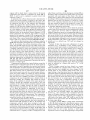
In a MPEG or other video coding system, regions of each
_
frame may be independently coded for later, independent
(22) Flled'
Apr‘ 25’ 2000
extraction or processing directly from a compressed bit
(51)
Int. Cl.7 ........................ .. G06K 9/36; H04N 7/087;
(52)
US. Cl. ..................... .. 382/243; 382/239; 348/722;
348/473; 37504008
Field of Search ............................... .. 382/243 238
H04N 5/222; H04N 7/12
(58)
ABSTRACT
Stream An encoder/transcoder receives raW Video, Standard
compressed video or compressed video already having inde
Penden?y Coded regions (“ICRS”) that are to be edited in
some manner. The encoder/transcoder permits user creation
of regions’ and provides automatic tracking features to
382/236 239. 375/240 12 240 15 2410 08’
identify and select those objects or regions through multiple
240 56, 328/473 722,341 $5,345 /'719’
frames (notwithstanding object movement). The encoder/
'
(56)
’
’
’
’
transcoder re-uses as much compressed input data as is
References Cited
available in generating an output, and so, may be used for
real-time encoding and editing processes. To this effect, the
US. PATENT DOCUMENTS
5,168,356 A
12/1992
Acampora et a1. ........ .. 358/133
5,543,931 A
5,953,506 A
8/1996 Lee et a1. .............. .. 358/335
9/1999 Kalra e161.
.. 395/20061
5,995,668 A
11/1999 Corset et a1. ............. .. 382/233
encoder/transcoder re-uses original bit stream data as Well as
original or neW motion vector data in compiling an output,
_
_
of any mlX of them as aPPmPnm
21 Claims, 14 Drawing Sheets
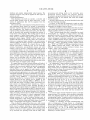
IMCGMEEEESED"?
165/:___\/.I9,E,9lv,/_Q19ES,,_E
107
*mcomp‘né's'siéf“
I
I
I
111
USER CREATES'GEOGRAPHIC
113
115
REGION OR IDENTIFIES
OBJECT AS REGION
TRANSCODE/ENCODE vloEo
“9
121
DEVELOP R MAP,
‘AS NECESSARY...
DET SLICING FOR
I
I‘
EACH MOD. FRM
DECODE TO
SPATIAL DOMAIN
129‘
EEEEE E’
COMPRESS AND SLICE
I RE-DO MOTION ESTIMATION
EACH FRAME ACCORDING i CONSTRAINED TO SAME
TO ITS REGION MAP
'
l
I
REGION OF BASE FRAME
BIT STREAM ENCODE/
I
INSERT SLICE CODES
L ******************* *7
AND REGION MAP
1
__
IBITSTREAM WITH REGION MAPS AND
iINDEPENDENTLY CODED REGIONS (ICRS)
D
---- “L221
U.S. Patent
I
I
I
I
I
I
I
I
Apr. 22, 2003
Sheet 3 0f 14
"RAW"
COMPRESSED
VIDEO
MPETG vIDEO
113
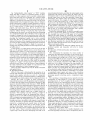
F|G_ 4 /
SELECT
/201
USER CREATES I
FRAME
203
GEOGRAPHIC REGION ;
I
:
l
US 6,553,150 B1
/
OR IDENTIFIES OBJECT:
LOCALLY STORE
COMPRESSED GOP
RAM
AS REGION I
207 \2O5
209
i
I
‘ LOCALLY STORE DE-
I
ZOOM/
COMPRESSED GOP
CHG FRM
I
I
211\ DISPLAY CURRENT IMAGE AND J \213
ID ANY EXISTING REGIONS
I
I
I
I
USER SELECTS NEW REGION(S)
215\ FOR IRC OR CHANGES EXISTING
REGION (COMPRESSION DATA
AVAILABLE)
I
.I
119\
DEVELOP R. MAP / DET
SLICING FOR EACH MOD. FRM
I
121\ COMPRESS AND SLICE EACH FRAME ‘
ACCORDING TO ITS REGION MAP
123\ BIT STREAM EN'CODE / INSERT
SLICE CODES AND R. MAP
217
219~\
5
“
:::§B-221
U.S. Patent
Apr. 22, 2003
Sheet 4 0f 14
US 6,553,150 B1
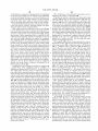
USER SELECTS NEW REG|ON(S) FOR
IRC OR CHANGES EXISTING REGION
(COMPRESSION DATA AVAILABLE)
|_PICK PNT. ON SOREENT/223
227
SELECT EX.
REGION
_E__U1GS__|
I“2u+In_I2
\TT“
A_4II___DF_23E1NT_O _.
ERN_GI|I
:PiE)Au“m%
wGANO
ME
WW
Im
A
wN
RmA
RO
l
u
m
_“C
PG
EU
N
EUW
ON
n
A
BC
l
u
G
U
A
EEG
m3
Rm
6%
Ev
EB
I
A
DWA
Lawn
A
Pm
9G
MIG
AG
M
Em
A
D
I
A
UWBM
?OEATUmI NAgTNRER_m“EFnOTuNAAD
R__U80TEIUN "ES
\GDATNRPANTIP_GSRSII_D.OVII.02ONCA(A2R_ELNA3SY%
um
AuGm1mmRamqOFwSOB A$W.N"_NFSEUSA
nNWDNNM3Q_OW
4
-I_H LEHU
JOT__
_5_>7
_
_2
__l
_
LGCEC_SR__FOE_TALET_/E_HAE
_EPI“FTTNAFSBWU
T:Mn“O?H_PlSB.AC
_N
_TE
U
D
_
/END_2A_ME#
n
AT
“R
w
n
D2
CH
__VI3_
F"N_G|RA.B“HI.A"_FEONAG\Y_NH_onluG“N6.DMG_2T_ “HAI1. I_2/
_MuR-O.mSFEaI .“
T
_
w
U.S. Patent
Apr. 22, 2003
Sheet 5 0f 14
US 6,553,150 B1
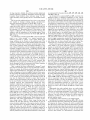
UsER OREATEs GEOGRAPI-IIO 113
REGION OR IDENTIFIES
/
OBJECT AS REGION
119
IFOR EACH MOD{FRAME
I
I
I
I
I
DEVELOP R. MAP /i
,
OBTAIN # OF REGIONs /253
DET sLIOING FOR:
EACH MOD‘ FRM'
IN FRAME
i
255
l
l
II
l
I
I
/257
YES
HAVE REGIONS
BEEN ADDED?
INOREMENT NUMBER
OF LOCAL GROUPs
OR GLOBAL GROUPS
AS APPROPRIATE
l___I
i
l
i
LAY MAOROBLOOKs OUT
I
AOOORDING TO REGION GROUP
/259
l
lI
l
I
261
Il
CALCULATE SLICE
BOUNDARIES
I
CALCULATE TOTAL /265
l
l
l
l
l
l
I
|
l
I
II
STORE IN RAM
NUMBER OF SLICES
CREATE MAP FOR EACH
MODIFIED FRAME WITH ONE
ENTRY FOR EACH SLICE
OOMPREss A|\ID sLIOE EACH /121
FRAME ACCORDING TO ITS RM
I
BIT sTREAM ENCODE / INsERT /123
SLICE CODES AND REGION MAP
/263
U.S. Patent
Apr. 22, 2003
F|G_ 8
US 6,553,150 B1
UsER CREATEs GEOGRAPHIC
269
I13
REGION OR IDENTIFIES
BCK SIGN [R1] 01
/
OBJECT AIS REGION
02922
I;
FORGND [R3] 00
BCK [R4]
Sheet 6 0f 14
R
DET SLICING FOR /
EACH MOD. FFIM
00
I
COMPREss AND SLICE
I21
EACH FRAME ACCORDING /
FIG, 10
TO ITS REGION MAP
123
I ____________________________________ "I _______________ __/
I
BIT STREAM ENCODE/
CQMPRESSED
INSERT SLICE CODES
BITSTREAM FOR
EXISTING FRAME
REGIONS ONLY
HEADER INFO.
AND REGION MAP
I
I
I
I
I
289
“““ _‘
I
I
293 I
I
I
I
307
I
I
I
NEW Mv
I
DATA FOR
I
ENT. FRAME
I
I
I
I
301
\ INVEFISE HUFFMAN
/309
W
w
M
I
I
DCT, QUANT,
HUFFMAN CODE,
I
I
I
INsERT FRM. & SL.
HEADER INFO.
BITSTREAM DATA
BITsTREAM FOR
I
ENT. FRAME
NEW W +
I
RESIDUALS DATA I
I
I
I
I
I
DCT AND
903 ORIG. HUFFMAN I
OUANTIzE NEW Mv
CODING
I
+ REsIDUALs DATA 297
I
COMBINE DATA:
NEW HUFFMAN /303 INSERT NEW
CODING
+
NEW HEADER INFO.
COMPRESSED N
=+~
I
I
DCT AND OUANTIzE I
CODE EXISTING
I
I
I, /295
287
311
OUTPUT SIGNAL
HEADER INFO,
FOR ALL SLICES
‘305
299
I
I
I
I
I
I
I
I
U.S. Patent
Apr. 22, 2003
US 6,553,150 B1
Sheet 7 0f 14
USER CREATES GEOGRAPHIC REGION
OR IDENTIFIES OBJECT AS REGION
I
DEVELOP R. MAP / DET SLICING
FOR EACH MOD. FRM
/119
121
J1______ __
RETREIVE SLICE BOUNDARIES COMPRESS ANDI
SLICE EACHI
AND REGION MAP FROM RAM
FRAME;
YES
ACCORDING TOE
ITS REGION MAP:
RETREIVE FRAME
DETERMINE FRAME /275
TYPE (I,P,B)
USE REG. MAP AND SLICE
COORDINATES TO SELECT ANC. PRM /277
AREAs PoR SAME RG; CDNSTRAIN
MV SEARCH ONLY TO THOSE AREAs
BIT STREAM ENCODE /
INSERT SLICE CODES
AND REGION MAP
TYPE (|,P,B) AND
APPLY sAME TYPE
U.S. Pate nt
Apr. 22, 2003
315x‘
Sheet 8 0f 14
US 6,553,150 B1
333 333 333 331 333 333 333
i
XEBOPHIFIFIFIFIFIWI
§N332 332 ‘332 332
319
326
\
325— STAR_T:OOOOO1 B5
(E I
327— usEFi; 000001 B2
321
328—~CODE_/GLOBAL RG1
FH ISLISLISLISLISLISL|"'I
\
ISLH lCOMPRESSED IMAGE DATA]
323
363
328~CODE/GLOBAL RGJ
33\3
3291STAR_T:OOOOO1 B8
356
\sTART;000001xx
334— usEFi: 00000132
_
.
341_GROUP MAPMWVJ] 347 STARET.OOOOO1OO
=
353'CODENOTAL # SLICES
343_CODE/LOCAL RGN
f
&
335
355—CODE/REGION MAP:[t1...tN,]
\
r
j
\
337
1
J
U.S. Patent
Apr. 22, 2003
330
f
\
Sheet 9 0f 14
US 6,553,150 B1
\
J
FIG. 14
FIG. 15
343
10 FIG. 16
357
0000000000100000000 FIG, 17
35,9
1111110110001101111
18
36,1
0000001001010010000
0000001001110010000
1111111111010010000
19
FIG-20
FIG. 22
000000100000000000
365
110110001011111111 /
001001010100000000
001001110100000000 /367
111111011111111111
FIG. 21
FIG. 23
U.S. Patent
Apr. 22, 2003
F
Sheet 10 0f 14
US 6,553,150 B1
\
FIG. 24
/369
/371
\
TV5j/373
375
COMPRESSED
VIDEO
377
STATIC IMAGE
381
APPROPRIATE
REGION CONVERTED
TO SPATIAL DOMAIN
383\
/\
389
391
COMPRESSED SPATIAL DOMAIN hag
REGIONS
REGIONS
393
395
MIX PIXEL DATA
I
[ORIGINAL
LOGO (0)]
(1-0) + +———>f
I
NEW MOTION SEARCH
399
+ COMP. (APPLY SAME /
{I
405
403
ADJUST
BUFFER SIzE
409
27/
'2
COMPRESSED
VIDEO
FRIvI. TYPE)
'
BITSTREAIvI
ENOODE
/401
FIG. 25
U.S. Patent
Apr. 22, 2003
US 6,553,150 B1
Sheet 11 0f 14
429
413
415
COMPRESSED
VIDEO
411
REGION
SELECTION
431
APPROPRIATE
REGION CONVERTED
TO SPATIAL DOMAIN
A
433
/437
COMPRESSED
REGIONS
411
SPATIAL DOMAIN ‘_
REGIONS
‘e’ 417
I
421
HUE TRAP
USSEELR
COLOR
SELECTED /423 ANGLE
OOLORS
/419
I
MULTIPLY HUE
ANGLE IN OOLOR
REPL
A
TRANSFORMATION
OOLOR
ANGLE
\425
427
,
,///7//
//
.
/445
I,
ADJUST BUFFER
SIzE
W
NEW MOTION SEAROR
+ COMP. (USE SAME \439
FRAME{I TYPE)
BITSTREAM
443
COMPRESSED
VIDEO
I
/441
ENCODE
447
FIG. 26
U.S. Patent
Apr. 22, 2003
Sheet 12 0f 14
US 6,553,150 B1
/452
_
COMPRESSED
453
VIDEO
é 455
/463
451
é
FRAMES TO BE
455
FRAMES TO BE RETAINED
RETAINED WHICH ARE
DEPENDENT UPON
D|SCARDED FRAME
WHICH ARE NOT
K
465
DISCARDED
DEPENDENTFRAME
UPON
\_, ,, f/ai
,lI‘
459
%/%’/
(/2 '
j
:
CONVERT AFFECTED
FRAMES TO REMOVE
461
DEPENDENCIES (B TO I,
B TO B-FORWARD, B TO
B-BACKWARD, P TO I)
SPATIAL
CONVERT
DOMAIN
TO
& RE-COMPRESS
ADJUST BUFFER
SIZE
473
\
467
U.S. Patent
Apr. 22, 2003
Sheet 13 0f 14
47?
479
4
481
US 6,553,150 B1
y
COMPRESSED
VIDEO
1/
,
l/
V
V
f
A
USER SELECTS
2
SPLICE POINT
/485
/\
COMPRESSED
FRAMES NOT
AFFECTED BY SPLICE
/487
FRAMES INTENDED FOR END
PRCDuCT WITH DEPENDENT
DATA DATA CUTOFF BY SPLICE
+
+
v
'55‘
I;
I
CoNvERT AFFECTED
-4 \
I
l
FRAMES TC REMovE
_ +
I
;
\ A ~
,. DEPENDENCIES (B TO I,
iiW/z +
B TO B-FCRWARD, B TO
B-BACKWARD, P TC I)
491CoNvERT
\
TO
SPATIAL
& RE-CoMPRESS
DOMAIN
\
I
_________ __»L_____/_423
ICCMPRESSED DCMAIN:
ADJUST BUFFER
SIZE
i
CCNvERSIoN
I
___.._____.___,____________
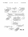
FIG. 28
U.S. Patent
Apr. 22, 2003
US 6,553,150 B1
Sheet 14 0f 14
COMPRESSED
REGION
SELECTED
vIDEO
SELECTION
|MAGE(S)
'
501
509
jig;
507
EAT‘ AT
511
: ‘T
JOE’S
,
505
513
APPROPRIATE
5%
'
REGION CONVERTED A
ggggégggLvEé
TO SPATIAL DOMAIN
k
A
COMPRESSED
REGIONS
517
SPATIAL DOMAIN
REGIONS
__
l
513
I
I‘? I
SQTAT
ES
519
DETECT OBJECT
(REGION)
TO ‘HE
REPLACE
I
I=IT SUBSTITUTE /521
TO AREA TO BE
~
REPLACED
j /523
525
ADJUST
I
NEW MOTION SEARCH + COMP.
ADJUST
BUFFER
(USE SAME PRM TYPE)
'
*
JOE'S :
-
BITSTREAM
5
ENCODE
SIZE
533
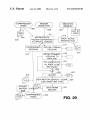
FIG. 29
515
US 6,553,150 B1
1
2
IMAGE SEQUENCE COMPRESSION
often require that frames be re-ordered and re-encoded in a
FEATURING INDEPENDENTLY CODED
REGIONS
different format (e.g., to depend upon different frames), and
therefore is regarded as one type of “editing.”
In most of the examples given, since editing or processing
is typically done entirely in the spatial domain, a video
The present invention relates to image sequence com
pression. More particularly, this disclosure provides a com
signal must typically be entirely decompressed to the spatial
domain, and then recompressed. These operations are typi
cally required even if only a small part of an image frame (or
group of frames) is being edited. For example, taking the
pression system that utilizes independently coded regions to
permit select extraction of image objects, or editing of select
areas of an image frame, Without necessarily decompressing
all image data in each frame. This disclosure also provides
a mechanism of tracking the objects and regions across
10
multiple frames such that, if desired, they may be indepen
dently coded and extracted from a video sequence.
BACKGROUND
is typically entirely decompressed and edited. If it is desired
15
Conventional editing or other processing of ?lm or video
images is performed in the “spatial” domain, that is, upon
actual images rather than upon a compressed representation
of those images. Since the ?nal product of such editing or
processing is frequently an uncompressed signal (such as a
typical “NTSC” television signal), such editing or process
ing can sometimes With today’s digital editors and comput
ers be accomplished in real-time. With increasing tendency
toWard high resolution pictures such as high de?nition
television (“HDTV”), hoWever, Internet, cable, television
to form a compressed output signal, frames of the edited
signal must then typically be compressed aneW.
In this regard, many compression formats are based upon
“motion estimation” and “motion compensation.” In these
compression formats, blocks or objects in a “current” frame
are recreated from similar blocks or objects in one or tWo
25
netWork and other service providers Will likely all have to
begin directly providing compressed signals as the ?nal
product of editing. As used herein, the term “video” Will
refer to any electronic signal that represents a moving
picture sequence, Whether digital, NTSC, or another format.
One problem relating to the neW digital standards relates
“anchor” frames; “motion estimation” refers to a part of the
encoding process Where a computer for each block or object
of a current frame searches for a similar image pattern Within
a fairly large area of each anchor frame, and determines a
closest match Within this area. The result of this process is
a motion vector Which usually describes the relative position
of the closest match in an anchor frame. “Motion compen
sation” refers to another part of the encoding process, Where
differences betWeen each block or object and its closest
match are taken, and these differences (Which are ideally all
Zeros if the match is “good”) are then encoded in some
compact fashion, often using a discrete cosine transform
(“DCT”). These processes simply imply that each portion of
to efficiently and quickly processing video; With video
the current frame can be almost exactly reconstructed using
the location of a similar looking portion of the anchor frame
stored or transmitted in compressed format under the neW
standards, it is dif?cult computationally to decompress
video, process that video in the spatial domain, and then
recompress output video. Examples of processing com
case of logo insertion in the bottom right corner of an image
frame, it is extremely dif?cult to determine Which part of a
compressed bit stream represents a frame’s bottom right
corner and, consequently, each frame of the video sequence
35 as Well as difference values. Not every frame in a sequence
is compressed in this manner.
pressed video prior to display include providing fast
Motion estimation is very computationally expensive. For
example, in applying the MPEG-2 standard, a system typi
forWard, reverse and other effects typically associated With
VCRs. Other processing examples associated With the pro
duction or broadcast of video include color correction, logo
insertion, blue matting, and other conventional processes.
To take one example of this computational dif?culty, in
logo insertion, a local television station might receive a
compressed satellite feed, insert its oWn TV station logo in
cally takes each block of 8x8 pixels and searches for a
closest match Within a 15x15 pixel search WindoW, centered
about the expected location for the closest match; such a
search involves 64 comparisons to ?nd the closest match,
and each comparison in turn requires 64 separate subtrac
tions of multi-bit intensity values. When it is considered that
a typical image frame can have thousands of 8x8 pixel
45
blocks, and that this searching is typically performed for the
a corner of the image that Will be seen on vieWers’ TV sets,
and then broadcast a TV signal over cable, back over
majority of frames in a video sequence, it becomes quite
apparent that motion estimation is a computationally expen
sive task.
With the expected migration to digital video and more
satellite or through the airWaves. Conventionally, the pro
cessing could be performed in real time or With a short delay,
because it is relatively easy to decompress an image, modify
that image in the spatial domain and transmit a spatial
compact compressed transmission formats, it is apparent
domain signal (e.g., an uncompressed NTSC signal). With
that a de?nite need exists for quick compression systems and
HDTV and other neW digital standards, Which call for all
for systems Which provide quick editing ability. Ideally, such
transmissions in a compressed format, this quick processing
becomes much more dif?cult, since it is very computation
ally expensive to compress a video signal.
a system should permit decoding and editing of a com
55
pressed signal (e.g., VCR functions, logo insertion, etcetera)
yet permit real-time construction and output of compressed,
All of the video examples given above, e.g., logo
insertion, color correction, fast forWard, reverse, blue
matting, and similar types of editing and processing
procedures, Will collectively be referred to interchangeably
edited video signal that can be accepted by HDTV and other
neW digital systems. Ideally, such a system Would operate in
a manner compatible With existing object-based and block
based standards and desired editing procedures, e.g., such
as “editing” or “processing” in this disclosure. “Fast for
Ward” and similar features commonly associated With a
video cassette recorder (“VCR”) are referred to in this
manner, because it may be desired to change the sequence or
compressed signal, as Well as other forms of editing and
processing. Further still, such a system ideally should be
display rate of frames (thereby modifying an original video
signal) and output a neW, compressed output signal that
includes these changes. The compressed output signal Will
that it can specially handle a logo to be inserted into a
implemented as much as possible in softWare, so as to be
65
compatible With existing computers and other machines
Which process video. The present invention satis?es these
needs and provides further, related advantages.
US 6,553,150 B1
3
4
SUMMARY
domain data and, second, taking motion vectors and residu
als associated With the dependent frame and “building” the
The present invention solves the aforementioned needs by
dependent frame’s content using “pieces” of the already
providing a system having independently coded regions.
decompressed anchor frame. This form of the invention calls
Using these regions, one may specially compress and
for generating a compressed output signal by providing a
encode a data sequence in a manner that permits extraction
user With ability to designate spatial domain data in a
or editing of select objects in the spatial domain, Without
dependent frame, by automatically associating data from
need to decode and decompress entire sequences. If it is
desired to modify a compressed output signal to include
modi?ed data for an object (e.g., for an edited object), neW
data can be inserted as appropriate in the place of the
another, anchor frame With that data, and by compressing an
output sequence in a manner such that the dependent frame
is compressed into motion vector-plus-residual format, With
all motion vector dependency of the dependent frame con
strained to only point to associated data of an anchor frame.
Other forms of the invention are set forth by the claims
extracted object; With the object being independently coded,
all other compressed data for the sequence (e.g., background
or other speci?c objects) may be exactly re-used. In real time
applications, this ability facilitates editing and production of
a compressed output signal using standard computer and
beloW, including various methods, apparatuses and improve
15
editing equipment. As can be seen therefore, the present
ments. In more particular aspects, these forms of the inven
tion may be implemented as video or audio encoders,
transcoders and editing devices.
The invention may be better understood by referring to
the folloWing detailed description, Which should be read in
invention should have ready application to production, post
production, netWork syndication, Internet, and other appli
cations Which call for the production of compressed video,
audio and other signals.
conjunction With the accompanying draWings. The detailed
description of a particular preferred embodiment, set out
The invention provides an apparatus that produces a
beloW to enable one to build and use one particular imple
signal representing multiple compressed data frames. The
mentation of the invention, is not intended to limit the
apparatus may be applied to audio or video data, or any other
type of data that is suitable for storage or transmission as a 25 enumerated claims, but to serve as a particular example
thereof.
sequence of related data frames. In the preferred
embodiment, this form of the invention is applied to com
BRIEF DESCRIPTION OF THE DRAWINGS
pressed video frames to generate independently coded
regions as part of an output video sequence. The preferred
embodiment may be applied by a netWork or video produc
tion house to generate an image sequence in compressed
FIGS. 1—10 illustrate the arrangement and operation of an
encoder/transcoder that implements principles of the present
invention.
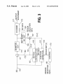
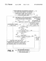
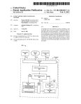
FIG. 1 indicates primary functions of the encoder/
transcoder.
FIG. 2 is a component level diagram, shoWing hoW
format (e.g., satellite transmission, DVD program, video
tape or other program) in a manner optimiZed for quick or
real-time editing. To take a feW examples, With a com
pressed image sequence already processed to have indepen
35
dently coded regions, a local television station may insert
output video signal.
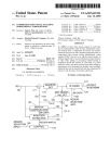
FIG. 3 is a How diagram shoWing M.P.E.G.-2 compres
sion in the context of independently coded regions.
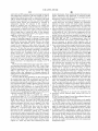
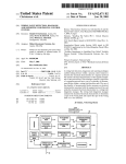
FIG. 4 is an expanded ?oW diagram, and indicates further
functions performed Within block 113 of FIG. 1.
ing the entire image sequence, i.e., by processing only one
or a small number of independently coded regions.
Alternatively, the preferred embodiment may also be imple
mented in a digital VCR or by a local television station; by
performing minor editing or processing (e.g., signal mixing,
frame re-ordering for fast forWard, logo insertion, etc.)
Without having to completely re-encode an entire video
sequence, these entities may more easily generate a digital
(HDTV) output signal in real-time or close to real-time.
According to a ?rst form of the invention, a compression
45
system encodes at least one data frame as an anchor frame
and at least one other data frame in dependent format, such
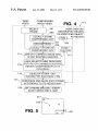
FIG. 5 is an illustration of a visual display Where existing
regions are highlighted to a user Who Will modify existing
regions, frame order, or add neW regions.
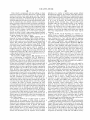
FIG. 6 is an expanded ?oW diagram, and indicates further
functions performed Within block 215 of FIG. 4.
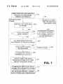
FIG. 7 is an expanded ?oW diagram, and indicates further
functions performed Within block 119 of FIG. 1.
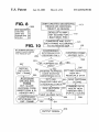
FIG. 8 is an illustration of a table that may be used for
each frame to track edits, a “registry of edits” as it Will be
labeled further beloW.
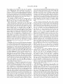
FIG. 9 is an expanded ?oW diagram, and indicates further
that each dependent frame may be recreated from one or tWo
anchor frames. This form of the invention calls for identi
fying at least tWo data sets (appearing across multiple image
frames) that are to be compressed independently of one
another, and also for constraining motion search and com
softWare implementing the preferred embodiment is imple
mented to process an input video signal and to generate an
logos and a post production house may provide color
correction Without completely decompressing and process
55
pensation such that motion vectors for each data set in a
dependent frame may only point to the same data set in one
functions performed Within block 121 of FIG. 1.
FIG. 10 is an expanded ?oW diagram, and indicates
further functions performed Within block 123 of FIG. 1.
or tWo anchor frames. “Data sets” can refer to an object that
FIGS. 11—24 are used to explain a signal format for a
appears in multiple frames (the object can vary in shape siZe,
video sequence, Where the signal itself includes information
color, intensity, etc.), as Well as a static shape and position
suf?cient to identify an object or frame location that has
(e.g., each screen’s loWer right-hand corner, irrespective of
been independently coded, and to identify Which image
image content).
slices in a sequence permit decoding of the object of interest.
In a second form of the invention, there Will be at least
tWo frames, one of Which is to be compressed as a dependent
frame, and another of Which is to be compressed as an
signal, including a video sequence having many groups of
anchor frame. Typically, the dependent frame is recreated by
?rst decompressing the anchor frame to generate spatial
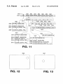
FIG. 11 illustrates the hierarchy of a basic MPEG format
65
pictures (GOPs). Each GOP includes multiple frames, each
frame includes multiple slices, and each slice includes
compressed image data. FIG. 11 also shoWs bit stream codes
US 6,553,150 B1
5
6
for header information, for each of sequence, GOP, frame
and slice level tiers. FIG. 11 further shoWs hoW region group
de?nition and region map information are inserted into this
FIG. 21 is similar to FIG. 15, eXcept that FIG. 21 shoWs
the ?rst mentioned mapping scheme for the ?rst frame of
FIG. 12. As can be seen from FIG. 21, its image data
preferred signal format.
represents the position of the ball in the upper right hand
corner of the ?rst image frame; FIG. 21 de?nes eighteen
image slices instead of the nineteen image slices of FIG. 15.
FIG. 22 illustrates the ?rst mapping scheme applied to the
eXample of FIG. 21. In particular, FIG. 22 illustrates the
entire region map including three tables, one for each of
FIGS. 12—14 illustrate a group of three image frames,
Where a ball appears to move from right to left across these
frames.
FIG. 12 shoWs the ball at the upper right hand corner of
a ?rst image frame.
FIG. 13 shoWs the ball in the middle of a second image
frame.
FIG. 14 shoWs the ball at the left side of a third image
frame.
FIG. 15 corresponds to the third image frame (FIG. 14)
10
15
and illustrates one methodology for hoW regions might be
created and sliced in a MPEG-2 format, Where region “A”
corresponds to ball only, region “B” corresponds to a blue
one for each image slice having background data (i.e.,
areas having both ball and background. The rectangles of
FIG. 15 represent nineteen image slices and are labeled “A,”
“B” or “C” only for purposes of illustrating Whether the slice
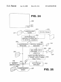
to explain creation of a globally de?ned region group
corresponding to the bottom right hand corner of each image
frame. Such a global region group is de?ned in logo inser
contains data belonging to these regions. Importantly, the
preferred MPEG-2 format usually requires a neW image
25
a great many more slices Would be indicated than nineteen
slices seen in FIG. 15, Which is used for illustration and
entirety of each image frame in a video sequence.
FIGS. 25—29 are used to describe several editing appli
cations facilitated by the use of independently coded
FIG. 16 shoWs a hypothetical group map Where tWo
globally de?ned region groups have been de?ned for the
sequence (a ball and a child) and a one bit entry is provided
for each globally de?ned region group to indicate Whether it
is present in the GOP of FIGS. 12—14. [Otherwise stated,
regions.
FIG. 25 provides a How diagram for logo insertion; in
connection With FIG. 25, it is presumed that a compressed
video signal input already has an independently coded
FIGS. 12—14 include the image of a ball but not of a child,
35
FIGS. 17—19 shoW a ?rst region mapping scheme, corre
sponding to the third frame of FIGS. 14 and 15. Each of
compressed video signal input.
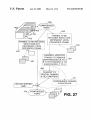
FIG. 27 presents a How diagram shoWing one method of
FIGS. 17—19 shoW a different one of three tables of the
fast forWard or reverse play.
region map.
FIG. 15. Each entry indicates Whether image data for the
region at the bottom right hand corner of each image frame.
FIG. 26 presents a How diagram for color correction; in
connection With FIG. 26, it is presumed that one Wishes to
change the color of an actor’s shirt, Where the shirt or the
actor have already been independently encoded Within a
present in this GOP).]
FIG. 17 shoWs a ?rst table for region “A” of FIG. 15. The
table has nineteen entries, one for each image slice seen in
tion applications, such that a corner of each frame is
inherently independently coded for ready logo insertion,
Without complete decoding and decompression of the
explanation only.
Which presumably appears elseWhere in the image sequence;
thus, the bit entries are “1” (signifying that the ball is present
in this GOP) and a “0” (signifying that the child is not
FIG. 23 illustrates the second mapping scheme applied to
the eXample of FIG. 21. In particular, FIG. 23 illustrates the
entire region map including tWo tables, one for each image
slice having ball data (i.e., regions labeled “A” or “C”) and
regions labeled “B” or
FIG. 24 is a hypothetical image frame shoWing a local
television station logo “TV5” Which has been inserted in the
bottom right hand corner of the image frame. FIG. 24 is used
sky background, and region “C” corresponds to “boundary”
slice for each neW line of macro-blocks such that in practice
regions “A,” “B” and “C” of FIG. 21, each having eighteen
data values corresponding to eighteen image slices.
45
FIG. 28 presents a How diagram shoWing the splicing
together of tWo image sequences.
FIG. 29 presents a How diagram shoWing the splicing
together of an image sequence With an image, or second
region “A” is found in the corresponding image slice.
image sequence; the image or second image sequence,
represented as a billboard close-up featuring the slogan
FIG. 18 is similar to FIG. 17, eXcept it shoWs the table for
region “B” of FIG. 15.
FIG. 19 is similar to FIG. 17, eXcept it shoWs the table for
region “C” of FIG. 15.
FIG. 20 presents a second region mapping scheme.
independently coded region of the ?rst image sequence. The
processes represented by FIGS. 27 and 28 may be employed
in cases of miXing tWo image sequences together, Where the
Instead of separately identifying transition regions for both
second image sequence is to be inserted into an indepen
“EAT AT JOE’S” is illustrated as being miXed into an
ball and background (as Was illustrated by FIGS. 15 and
17—20), only tWo tables are used. In the ?rst roW of FIG. 20
(i.e., a ?rst table), values represent Whether a corresponding
image slice has any ball data (Whether or not background
data is also present). A second roW (i.e., second table)
indicates Whether a corresponding image slice has any
background data (Whether or not ball data is also present).
One difference betWeen the tWo mapping schemes is that the
second mapping scheme, represented by FIG. 20, alloWs an
image slice to be associated With tWo different regions. The
mapping scheme of FIG. 20 is preferred especially When
many regions are to be used (and, thus, Where it might be
cumbersome to have separate regions dedicated to each
boundary betWeen objects).
dently coded region of the ?rst image sequence.
55
DETAILED DESCRIPTION
The invention summariZed above and de?ned by the
enumerated claims may be better understood by referring to
the folloWing detailed description, Which should be read in
conjunction With the accompanying draWings. This detailed
description of a particular preferred embodiment, set out
beloW to enable one to build and use one particular imple
65
mentation of the invention, is not intended to limit the
enumerated claims, but to serve as a particular eXample
thereof.
The particular eXample set out beloW is a preferred
implementation of several components that implement,
US 6,553,150 B1
7
8
facilitate and employ independently coded regions. The
invention, hoWever, may also be applied to other types of
processing and editing (such as by netWorks, post
production houses, studios, TV stations, Internet
systems as Well.
broadcasters, program distributors and the like) and by local
I. General Introduction.
distributors such as TV stations and cable and satellite
service providers.
This disclosure sets forth an encoder, a decoder and
several signal formats. Each of these items have a Wide
As used in this disclosure, the terms identi?ed beloW shall
variety of applications that Will be apparent from the
have the folloWing meanings.
description beloW.
A “frame” of data shall be interpreted to apply to audio,
audiovisual data, and any other type of data that is typically
transmitted in multiple, discrete frames.
The encoder takes a data sequence having discrete frames,
and compresses those frames for storage or transmission
such that “regions” of frames can be independently extracted
and decompressed. The frames are subdivided into these
10
“Software” includes any stored instructions that electroni
cally control the functions provided by a system, and spe
regions and then encoded using certain rules, such that they
ci?cally includes ?rmWare as Well as softWare.
may be decoded With necessary decoding the entirety of
every frame in the sequence. The encoder may be used to
15
“Video” includes image data that is transmitted or stored
electronically as a sequence of image frames, and shall
speci?cally include all television formats, irrespective of
neWly compress a “spatial domain signal” (that is, conven
tional analog or display-ready input signal) to have inde
pendently coded regions (“ICRs”), and it may also be
frame rate, color modulation schemes and other features
Which distinguish individual standards. For example,
applied in the form of a “transcoder,” that is, in a system that
receives a compressed input, modi?es it in some manner,
and then applies an encoder to provide a compressed output
signal With ICRs as desired. It is hoped that use of this
“video” includes formats used for video conference, com
puter monitor transmission and television formats Wherever
encoder Will make it relatively easy for TV netWorks,
(e.g., “MPEG” schemes and “H.261 ” and “H.263 ”) and
developed. “Video” speci?cally includes digital formats
(e.g., “DVD” and “HDTV”), differing compression formats
different conventional analog television formats (e.g.,
stations, broadcasters, post-production houses and other
entities to edit or process a compressed signal and provide
25
a compressed output at or near real-time. For example, use
of an encoder or transcoder as mentioned above for satellite
“NTSC,” “ AL” and “SECAM”).
An “anchor” frame includes any frame upon Which
another frame directly depends for reconstruction, and it
signal distribution may render it relatively easy for a doWn
stream TV station to insert its oWn logo and quickly retrans
mit a modi?ed signal, through editing only one ICR of
interest and re-encoding only the edited portion. If a
As non-limiting examples, in conventional “MPEG”
formats, dependent frames may be recreated from indepen
received signal has been already generated to have these
themselves depend upon other frames for reconstruction);
ICRs, then an encoder or transcoder may also be used by the
local TV station to facilitate quick editing.
both of these “I” and “P” frames Would be anchor frames if
It is hoped that use of these various elements Will make it
may be either an independent frame or a dependent frame.
dent “I” frames as Well as predictive “P” frames (Which
another frame uses them for reconstruction.
35
relatively easier to fabricate digital systems in hardWare and
softWare that can process signals and provide compressed
output signals at or near real-time. The embodiments
described beloW can be applied to audio signals or other
information suitable for transmission in a frame type format,
An “independent” frame includes any frame that does not
depend upon another frame for reconstruction, e.g., an
independent frame is compressed in a manner Where its
image content can be completely obtained Without decom
pressing any other frame. In conventional “MPEG” formats,
only “I” frames are independent.
but the preferred application is to video, especially HDTV
A“dependent” frame includes any frame that does depend
and digital standards that call for transmission or storage in
a compressed format. The preferred system described beloW
operates using “MPEG-2 ” compression standards
upon another frame for reconstruction. In conventional
“MPEG” formats, a dependent frame can include “P” frames
(indicating standard no. 2 proposed by the “moving pictures
45
(themselves depending upon either “I” or “P” frames, Which
are previously decoded) as Well as “B” frames (themselves
experts group”), but the system can be applied to any
depending upon one or tWo “I” or “P” frames Which are
compression format, including MPEG-1, MPEG-4, H.261,
previously decoded). Since “B” frames can depend upon
H.263 and other types of formats. While conventional sys
tems operate on analog television signals (e.g., While a
tWo anchor frames (one of Which can be later in the video
sequence), the frames are typically stored or transmitted out
of order. For example, if three consecutive frames are to be
encoded as “I,” “B” and “P” frames respectively, these
frames Would be stored or transmitted in the order “IPB” and
Would be decoded in this order and then reordered for
digital video disk (“DVD”) player typically provides an
analog television signal output), it is expected that With the
spread of Internet broadcasting and HDTV especially, more
systems Will necessarily accept compressed inputs, and one
primary application of the present invention is to facilitate
video processing systems (such as VCRs and disk players)
display.
55
A “current” frame includes Whichever frame is currently
Which provide a processed or edited compressed output
being processed. For example, When encoding a dependent
signal in real-time. Another primary application of the
frame, the dependent frame is the “current” frame and the
corresponding “anchor” frame(s) Would be Whichever one or
present invention is to video broadcast systems used in
satellite transmission, cable routing, Internet broadcasting,
tWo frames is used as a direct reference for compression and
reconstruction of the current frame.
netWork or TV station editing and similar types of systems
Where a compressed video signal is a desired output.
Thus, it should be apparent that there are a Wide variety
of systems to Which the elements and techniques described
beloW may be applied, including to home entertainment
systems (such as televisions, VCRs, disk players, home
routers or servers for video signals), video recording (such
as by netWorks, live sporting events and the like), video
“Coding” or “encoding” are used interchangeably, and
refer to compression of image frames to a compressed
format. The compressed format can be a conventional “IPB”
format de?ned by various “MPEG” standards, a compressed
65
bit stream (e.g., “I,” “P” or “B” frames Which then are
quantiZed, Huffman coded, etcetera, to simply be a stream of
numbers), or another format.
US 6,553,150 B1
9
10
An “independently coded region” or “ICR” includes
stream header information, such that the output signal can be
image data that is coded in a restricted manner, so that a
examined, ICR position derived from the signal, and this
portion of a video sequence may be encoded in dependency
upon each other only. As an example, if a “current” image
information used to extract each ICR from each frame. A
second format does not use this embedded “region map”
information, but instead relies upon default or constant
frame is to be encoded as a “P” frame (that depends upon a
different “I” frame) and it is desired to encode a set of actors
region information. For example, it may be desired simply
to have a static data group (e.g., a static object or ?xed
independently from a background image, then an “indepen
region such as the bottom right hand corner of each frame)
dently coded region” might be created separately for each of
the set of actors and the background. That is to say, each of
the “P” frame and the “I” frame could be divided into tWo
regions, and each region (e.g., the set of actors or the
background) could be extracted and recreated from the video
sequence Without having to decode the other region (the
background or the actors, e.g., With this latter data remaining
in a compressed format). If it is desired to edit a region, for
example, to change the color of a particular actor’s shirt, this
“color correction” may be accomplished Without necessarily
decoding the background region, and a color corrected
signal may then be re-encoded into bit stream format and
inserted in the place of the original bit stream data for the set
of actors. [In this example, the background data Would not
have to be changed, although it might be necessary to
modify some front end parameters for the image frame, such
as buffer siZes.]
A“data group” or “region group” refers to any set of data
that is to be grouped together across several frames; the
individual pixel values of a data group may change from
frame-to-frame. For example, if it desired to independently
that is constant for all frames of a “GOP” or image sequence.
10
15
In this instance, information on region location could be
provided in a user manual, indicated on a label for a video
disk or tape, or via some other mechanism, and a speci?c
map for each frame Would not be needed.
Finally, the remaining FIGS. are used to exemplify some
uses for a signal having ICRs and a decoder, respectively.
For example, one use of an ICR signal is for enabling
ef?cient and quick editing by extracting and changing a
speci?c data group only. Techniques and systems for making
use of ICRs and the speci?ed signal formats are described
furthest beloW, With reference to FIGS. 25—29. These FIGS.
also illustrate operation of a decoder that may be used to
generate spatial domain data that can be employed for such
ef?cient and quick editing.
25
With this explanation in mind, the making and use of a
preferred encoder and transcoder Will noW be further
described.
III. Operation of Preferred Encoder and Transcoder.
A. OvervieW.
FIG. 1 illustrates the operation of a basic encoder or
encode a mountain that appears as one background image of
a moving scene, and each frame features a slightly different
transcoder that implements principles of the present inven
tion. Preferably, one image processing system accomplishes
perspective of the mountain, the mountain might be one data
group; its relative siZe and color might change from frame
to frame, but in each frame its data Would be grouped
together as a “region” and each region Would be separately
both functions and accepts any of (a) “raW” or uncom
pressed video 103, (b) already compressed video 105 With
out ICRs Which is to be processed to convert it to an ICR
format, or (c) already compressed video 107 having ICRs
encoded in each frame, such that across a frame sequence, 35 Which are to be edited or processed in some manner. As
the entire mountain can be singled out and extracted and
indicated by blocks 109 and 111, compressed video must
either be entirely bit stream decoded if there are no existing
decoded, independent of other compressed data.
These and other de?ned terms Will be further described
ICRs or, if there are existing ICRs, then those ICRs that are
to be selectively edited must be decoded. It should be noted
and applied beloW.
II. The Principal Parts.
that one purpose of the encoder or transcoder is to provide
FIGS. 1—9 are used to help describe the operation of an
a compressed output signal, and many of the procedures
encoder and transcoder. The encoder is used both to neWly
described beloW are utiliZed to take shortcuts (e.g., improve
encode video signals, and also as a part of a transcoder
Which either converts a compressed signal to an ICR format,
or reassembles an edited sequence into a compressed format. 45
processing speed) in deriving such a compressed output
Ideally, the result of either of these (encoder or
transcoder) processes is an ICR signal that may be displayed
or further used in editing. Several preferred formats for this
signal are described beloW, With reference to FIGS. 10—24.
presentation of some display to a user Who oversees the
The encoding or transcoding process typically involves
encoding process. A “user” as applied in this section of the
disclosure refers to one operating the encoder or transcoder
to cause the selection of, or rede?nition of, regions that Will
be independently coded. Typically, at least one static frame
Will be displayed Which permits the user to select groups of
data that Will be independently coded; the user can “drop and
One format involves embedding region information directly
Within an output signal. For example, in ?lming a program,
it might be desired to ?lm actors or other objects against a
blue background, such that the actors or objects may later be
combined With a speci?c scene (e.g., a jungle scene) via
electronic “blue matting.” In this instance, it might be
desired to separately encode the foreground (the actors or
signal.
drag” a cursor over image area to select an arbitrary region
on the screen. This region may be made static for all frames
55
selected, or it can be used initially identify an object, With
image processing softWare operating to automatically track
objects) as one or more ICRs and the background as another
the obj ect’s movement through multiple frames and to select
ICR to minimiZe processing required in the “blue matting”
procedure. Since the foreground actors or objects in this
example may move in position With respect to each frame,
it may be necessary to specify directly in the header infor
suitable corresponding regions throughout those frames
using Well knoWn tracking and image detection routines. A
mation for a compressed scene exactly Where to ?nd each
ICR among the bit stream data for that frame; several
formats for providing “region maps” are described beloW,
such that each object can be extracted from bit stream data
for each frame. Stated someWhat differently, this ?rst
“region map” format involves identifying each ICR in bit
primary purpose of these routines Will be to provide a
preliminary selection of object boundaries based upon a
frame range speci?ed by a user. If existing video already has
ICRs, then the display functions Will cause each existing
ICR to be highlighted, and permit a user to change existing
65 boundaries or add or delete ICRs.
Importantly, each frame to be visually displayed to the
user must typically be decoded, but as is implied by FIG. 1,