1
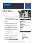
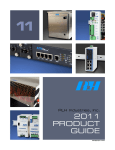
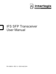
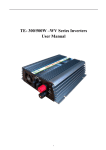
RLH Industries, Inc. The leader in rugged fiber optic technology. Unconditional Lifetime Warranty USER GUIDE U-005 2015B-0122 2 Channel POTS w/ Ethernet Fiber Link Card System SYSTEM INSTALLATION INFORMATION Introduction The 2 Channel POTS w/ Ethernet Fiber Link Card System provides a comprehensive method of multiplexing POTS channels over a single pair of multimode or single mode fibers. Additional POTS lines may now be added when available fiber is limited, helping to reduce equipment space, and lower overall equipment costs. The system includes two 10/100 Ethernet ports for LAN interconnection. All ports operate simultaneously over the fiber optic cable, and may be used with leased lines to build up private networks and private telephone networks. It is available in either single mode or multimode with the ability to operate up to 120km over single mode fiber. A typical complete system comprises one FXO/CO and one FXS/Sub module, or use FXS/Sub unit at each end for ringdown operation where direct connection to phones on both ends of the system is desired. The system requires a 24-48VDC power source and is covered by our Unconditional Lifetime Warranty. 2 Channel POTS w/ Ethernet Fiber Link Card System Contents Introduction ___________________________1 General Safety Practices _________________2 Special Handling Requirements ___________2 Acronyms _____________________________3 Applications ___________________________4 Installation _____________________________5 Operation _____________________________7 Key Features Status and Activity LEDs _________________7 • • • • • Ordering Information ____________________8 • • • • • Unconditional Lifetime Warranty Single or Dual Fiber Connector 2 channels of POTS Convenient LED status indicators 2 shared RJ45 UTP ports with 10/100 automatic Half or FullDuplex auto-negotiation Alarm indication function Compatibility with IEEE 802.3 10Base-T UTP, 100Base-TX, and 100Base-FX Devices Extends network span up to 74 miles miles (120km) Uses 24-48VDC local power Fiber Link Card is compatible with RLH card housings Specifications __________________________9 Warranty _____________________________10 Technical Support _____________________10 Specifications subject to change without notice. RLH Industries, Inc. • Tel. 866-DO-FIBER • Fax 714 532-1885 • www.fiberopticlink.com Page 1 General Safety Practices Intended Audience This guide is intended for use by knowledgeable telco/network installation, operation and repair personnel. Every effort has been made to ensure the accuracy of the information in this guide is accurate. However, due to constant product improvement, specifications and information contained in this document are subject to change without notice. Conventions Symbols for notes, attention, and caution are used throughout this manual to provide readers with additional information, advice when special attention is needed, and caution to prevent injury or equipment damage. The equipment discussed in this document may require tools designed for the purpose being described. RLH recommends that service personnel be familiar with the correct handling and use of any installation equipment used, and follow all safety precautions including the use of protective personal equipment as required. Caution - Severe Shock Hazard • Never install during a lightning storm or where unsafe high voltages are present. • Active phone lines may carry high DC voltages. Use caution when handling copper wiring. • The DIN chassis must be grounded using the ground screw to reduce the risk of damage from lightning. HVP information The intra-building port(s) of the equipment or subassembly is suitable for connection to intra-building or unexposed wiring or cabling only. The intra-building port(s) of the equipment MUST NOT be metallically connected to interfaces that connect to the OSP or its wiring. These interfaces are designed for use as intra-building interfaces only (Type 4 ports as described in GR-1089-CORE, Issue 4) and require isolation from the exposed OSP cabling. The addition of Primary Protectors is not sufficient protection in order to connect these interfaces metallically to OSP wiring. Special handling requirements Be careful when handling electronic components ATTENTION ELECTROSTATIC SENSITIVE DEVICES • This product contains static sensitive components. • Handle Fiber Link Cards at their edges only. • Follow proper electrostatic discharge procedures. The Fiber Link Card utilizes circuitry that can be damaged by static electricity. When transporting the card, carry it in an ESD safe container such as the antistatic bag provided with the card. Before handling cards, discharge yourself of static electricity by physical bodily contact with earth ground. When handling cards, hold by outer edges and avoid touching circuitry. Failure to follow ESD precautions may cause damage to the card and prevent proper operation. Page 2 RLH Industries, Inc. • Tel. 866-DO-FIBER • Fax 714 532-1885 • www.fiberopticlink.com Guidelines for handling terminated fiber cable • Do not bend fiber cable sharply. Use gradual and smooth bends to avoid damaging glass fiber. • Keep dust caps on fiber optic connectors at all times when disconnected. • Do not remove dust caps from unused fiber connectors. • Keep fiber ends and fiber connectors clean and free from dust, dirt and debris. Contamination will cause signal loss. • Do not touch fiber ends. • Store excess fiber on housing spools or fiber spools at site Acronyms Commonly used acronyms and abbreviations Acronym/Abbreviation POTS Plain Old Telephone Service (analog phone) FXO/CO Foreign Exchange Office or Central Office location FXS/Sub Foreign Exchange Station or Subscriber side location PBX Description Private Branch Exchange TX Transmit RX Receive MM Multimode SM Single Mode 2W Refers to 2 wire copper analog phone line VOIP Voice Over IP LAN Local Area Network MUX Multiplex LED Light Emitting Diode RLH Industries, Inc. • Tel. 866-DO-FIBER • Fax 714 532-1885 • www.fiberopticlink.com Page 3 Applications Optical fiber is immune to EMI/RF interference, ground loops, and high voltage surges from lightning or ground faults, and is ideal for electrically noisy environments such as near large power sources, electrical motors, and radio communications equipment. Additionally, copper twisted pair Ethernet is limited to 100m/328ft without extenders. Using fiber optic cable provides long distance service (up to 120km/74mi.) without any additional equipment. Safety benefits of fiber optics Placement of all-dielectric fiber optic cable (instead of copper) completely eliminates the presence of a remote ground, which dramatically increases safety of personnel and reliability of equipment. By using fiber optic cable, the 2 Channel POTS w/ Ethernet system provides absolute electrical isolation between fiber network devices. Connection Diagrams The diagrams below show the two different models of the POTS system. Refer to the Ordering Information and Specifications sections for additional information. 2 channel POTS w/ Ethernet system connection diagram 2 channel POTS w/ Ethernet system with ringdown circuit connection diagram Installation Page 4 RLH Industries, Inc. • Tel. 866-DO-FIBER • Fax 714 532-1885 • www.fiberopticlink.com Prior to installation • • • • • Check for shipping damage Check the contents to ensure correct model and powering options Make sure you have the correct fiber type and power available Have a clean, dry installation environment ready Observe anti-static precautions Required for installation: • • Suitable RLH card housing for the Fiber Link Card 24-48VDC power supply FXO/CO (Central Office) Side Unit The FXO/CO side unit provides the electrical-optical interface between PSTN or PABX 2-wire copper analog phone lines, Ethernet devices or LAN, and the optical fiber cable. FXS/Sub (Subscriber Side) Side Unit The FXS/Sub side provides the electrical-optical interface between the copper 2-wire POTS line devices (phones, fax, modem), Ethernet devices or LAN, and the optical fiber cable. Note: FXS/Sub units are electrically different from FXO/CO units and cannot be interchanged. When using the ringdown circuit, the FXS/Sub module is used at each end of the network. Install into Card Housing Install the Fiber Link Card into the desired RLH card housing by depressing the card retainer slightly while sliding the card into the guide rails. Contact your RLH representative about card housing options. Installation into RLH Fiber Link Card Housing RLH Industries, Inc. • Tel. 866-DO-FIBER • Fax 714 532-1885 • www.fiberopticlink.com Page 5 Connect optical fiber cable The optical ports may be equipped with ST, SC or FC fiber connectors. A fiber pair is required for operation with dual fiber models, TX is the signal output side and RX is the signal input side. Bi-directional single fiber models combine input and output, and require only a single fiber. Connect fiber cables to correct TX and RX ports. On dual fiber models, the TX port of on side must be connected to the RX port of the unit at the other side. Make sure the connections for dual fiber optics are flipped accordingly. Do not remove fiber cable caps until you connect fiber to the unit, watch for contamination. Connect Ethernet ports The two Ethernet ports use standard RJ-45 connectors. The Ethernet ports are 10/100M, full/duplex, auto negotiating. The ports have status indicators when operating. Refer to the LED indicators table for additional information. Connect analog phones The Fiber Link Card combines 2 POTS channels into a single RJ-45 connector. The POTS ports use the center 4 pins of the RJ-45 connector, which are then split out to standard RJ-11 female adapters for easy installation. Use the included adapter cable to attach RJ-11 connectors to the POTS card. PIN 1 (Any Color Pairs may be used) PIN 3 To Analog Phone Mux PIN 6 6 PIN RJ-11 Female PIN 3 PIN 3 PIN 4 PIN 1 8 PIN RJ-45 Male (Contact Side) PIN 4 PIN 8 PIN 6 Line 1 Line 2 To Customer Equipment RJ-45 to RJ-11 adapter connection diagram POTS Channel 1 2 RJ-11 Female Pin RJ-45 Male Pin 3 4 3 4 6 3 5 4 RJ-45 to RJ-11 pinout table Connect Power The POTS system accepts a 24-48VDC local power source. The power range is identified on the top of the card, near the power connector. Note: The power terminals are not polarity sensitive, and power wires may be inserted into either side. Attach the power wires to the screw down terminal on the front panel of the card. For ease of installation, the terminal block may be removed by pulling straight out. If removed, seat the terminal block firmly into the connector before applying power. Once power is applied, the system will begin operating automatically. Page 6 RLH Industries, Inc. • Tel. 866-DO-FIBER • Fax 714 532-1885 • www.fiberopticlink.com Operation On the Fiber Link Card, the yellow PHONE LEDs on the front panel indicated which POTS lines are being actively used. For both models, the LED indicators on each port indicate if the port connection and operation. The LNK LED is ON when the port is connected to a LAN or other active link, and the DATA LED blinks when the port is sending or receiving Ethernet data. Status and Activity LED display VDC INPUT TX RX DATA ENET PORT 1 LNK DATA ENET PORT 2 LNK CH1 2 CH. POTS MUX PHONE CH2 PWR FOC LOF RAI LED activity and status indicators Label Name Status PWR Power ON Power is ON ON Fiber connector disconnected OFF Fiber connector installed FOC Fiber Optic Connection LOF Loss of Frame RAI Remote Alarm Indicator DATA (TP ports) LNK (TP ports) CH1 (Phone ports) CH2 (Phone ports) Ethernet Data Ethernet Link Channel 1 Phone Port Channel 2 Phone Port Description ON Fiber or copper frame lost OFF Fiber or copper frame normal ON Loss of fiber or copper signal OFF Fiber or copper signal normal Blinking Ethernet data is transmitting or receiving OFF No Ethernet data activity ON Ethernet connected OFF Ethernet disconnected ON Channel 1 phone is off hook Blinking Channel 1 phone is dialing OFF Channel 1 phone is not active ON Channel 2 phone is off hook Blinking OFF Channel 2 phone is dialing Channel 2 phone is not active RLH Industries, Inc. • Tel. 866-DO-FIBER • Fax 714 532-1885 • www.fiberopticlink.com Page 7 Ordering Information Each 2 Channel POTS Mux Card is identified with the part number. Part Number Bi-Directional Multimode SC Multimode SC Multimode ST Bi-Directional Single-mode SC Bi-Directional Single-mode SC Single-mode SC Single-mode SC Single-mode SC Single-mode ST Single-mode ST Single-mode ST Description Side Distance Fiber Part Number CO Card A 2.4km/1.5 mi 62.5/50μm RLH-PM2P-01-CE-2 SUB Card B 2.4km/1.5 mi 62.5/50μm RLH-PM2P-02-SE-2 CO Card - 2.4km/1.5 mi 62.5/50μm RLH-PM2P-03-CE-2 SUB Card - 2.4km/1.5 mi 62.5/50μm RLH-PM2P-03-SE-2 CO Card - 2.4km/1.5 mi 62.5/50μm RLH-PM2P-04-CE-2 SUB Card - 2.4km/1.5 mi 62.5/50μm RLH-PM2P-04-SE-2 CO Card A 20km/12.4mi. 8~9µm RLH-PM2P-10-CE-2 SUB Card B 20km/12.4mi. 8~9µm RLH-PM2P-11-SE-2 CO Card A 60km/ 37mi. 8~9µm RLH-PM2P-14-CE-2 SUB Card B 60km/ 37mi. 8~9µm RLH-PM2P-15-SE-2 CO Card - 20km/12.4mi. 8~9µm RLH-PM2P-40-CE-2 SUB Card - 20km/12.4mi. 8~9µm RLH-PM2P-40-SE-2 CO Card - 60km/ 37mi. 8~9µm RLH-PM2P-41-CE-2 SUB Card - 60km/ 37mi. 8~9µm RLH-PM2P-41-SE-2 CO Card - 120 km/ 74 mi. 8~9µm RLH-PM2P-42-CE-2 SUB Card - 120 km/ 74 mi. 8~9µm RLH-PM2P-42-SE-2 CO Card - 20km/12.4mi. 8~9µm RLH-PM2P-50-CE-2 SUB Card - 20km/12.4mi. 8~9µm RLH-PM2P-50-SE-2 CO Card - 60km/ 37mi. 8~9µm RLH-PM2P-51-CE-2 SUB Card - 60km/ 37mi. 8~9µm RLH-PM2P-51-SE-2 CO Card - 120 km/ 74 mi. 8~9µm RLH-PM2P-52-CE-2 SUB Card - 120 km/ 74 mi. 8~9µm RLH-PM2P-52-SE-2 A complete system requires a FXO/CO and a FXS/Sub unit, or two (2) FXS/Sub units for ringdown function. Bidirectional single fiber models require an A Side and B Side unit for a complete system. Bidirectional optic wavelength may be special ordered. Contact factory for availability. Fiber Link Card models includes RJ-11 breakout adapter for easy connection to existing POTS lines Page 8 RLH Industries, Inc. • Tel. 866-DO-FIBER • Fax 714 532-1885 • www.fiberopticlink.com Specifications Transmission method Frequency modulated light via two optical fibers Maximum Fiber Attenuation / Distance* Multimode 850nm/1310nm/1550nm Single-mode 1310nm/1550nm Single Fiber, Bi-directional Multimode (62.5/125µm): 1.25mi./2 km range Single-mode (9/125µm): 12.4 mi./20km range 24.9 mi./40km range 37 mi./60km range Dual Fiber Multimode (62.5/125µm): 1.25mi./2 km range Single-mode (9/125µm): 12.4 mi./20km range 37 mi./60km range 74 mi./120km range *Note: Distances equated using industry standard fiber and connector attenuation of 3dB/ Km. Fiber condition, splices and connectors may affect actual range. Fiber Type (ST, SC or FC connectors) Multimode: 62.5/125µm, Single-mode: 8-9/125µm Consumption +2 to -11dBm Sensitivity Better Than -36dBm BER <10-9 Phone Connector RJ-45 shared for both POTS Channels, breakout cable included Audio Frequency 300Hz-3400Hz Impedance 200Ω 560Ω//0.1µF Baud Rate 9600 maximum Compression Ratio Class A in ITU G.711 Loop Current 25mA Ethernet 10/100M, full/duplex, auto negotiation Protocol IEEE 802.3 Data Rate 100 Mbps Max Packet Size 1518 bytes Ethernet Connector RJ-45 Power Requirements Nominal 24VDC ~ 48VDC Max Range 22VDC ~ 62VDC Max Power Consumption ≤5W Dimensions/Mounting L 7in. x H 4in. x W 1in. (177.8mm x 101.6mm x 25.4mm) Compatible with RLH Fiber Link card housings Operating Temperature 14°F to +122°F (-10°C to +50°C) Humidity 95% non-condensing RLH Industries, Inc. • Tel. 866-DO-FIBER • Fax 714 532-1885 • www.fiberopticlink.com Page 9 Warranty RLH is recognized throughout the world and offers the only UNCONDITIONAL LIFETIME WARRANTY in the industry. We are very proud of our warranty which simply states that the product is warranted to be free of defects in material and workmanship for the LIFE OF THE PRODUCT. RLH will replace this product, or part thereof, if it fails FOR ANY REASON, provided the defective part is returned to RLH Freight prepaid. This warranty is UNCONDITIONAL and valid even when this product has been abused, mishandled, or damaged as a result of a natural disaster. This warranty will reduce your costs and simplify your maintenance activities. Not all RLH products are covered by this warranty. To make a warranty claim, or schedule repair or replacement of your RLH product, please contact us for an RMA number. You will be promptly assisted by one of our warranty specialists. All returns must have an RMA number before we can receive any items. Technical Support Email: [email protected] 24/7 technical support: Toll Free 1-855-RLH-24X7 Toll Free 1-855-754-2497 Contact Information Corporate Headquarters: RLH Industries, Inc. 936 N. Main Street Orange, CA 92867 USA Phone: (714) 532-1672 Toll Free 1-800-877-1672 Toll Free 1-866-DO-FIBER Fax: (714) 532-1885 Email: [email protected] Web site: www.fiberopticlink.com RLH Industries, Inc. 936 N. Main Street, Orange, CA 92867 USA T: (714) 532-1672 F: (714) 532-1885 Page 10 Please contact your RLH sales representative for pricing and delivery information. Specifications subject to change without notice. RLH Industries, Inc. • Tel. 866-DO-FIBER • Fax 714 532-1885 • www.fiberopticlink.com