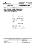
1
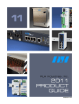
The leader in rugged fiber optic technology. technology. RLH Industries, Inc. Unconditional Lifetime Warranty USER GUIDE 2010D-1001 RLH 16 T1 Over Gigabit Ethernet Fiber Optic Multiplexer System IP transport of 16 T1/E1, 5 GE and 1 SFP GE optical over a single fiber RLH-TG- 2C-1 T1 over Gigabit Ethernet Introduction As a cost effective solution for the traditional telecom services migrating to IP packet networking technology, the 16 Channel T1 over Ethernet (T1 over IP) adopts the innovative TDM over IP technology, with IP circuit emulation that supports transporting up to 16 T1/E1s, 5 GE electrical ports and 1 SFP GE optical port. The GE uplink ports and user data ports are IEEE 802.3 compliant, 10/100/1000M auto-sensing Ethernet ports. This is ideal for transporting T1/E1 over GE copper or fiber. State-of-the-art design provides accurate timing signals and data bit stream reconstruction. Predefined system parameter profiles may be applied according to different application requirements. This system is also suitable for connecting to wireless equipment for rapid deployment of T1/E1 services. Key Features • 16 channels of E1/T1 over 1 Ethernet • 5 GE TP ports and 1 GE optical port, all 6 GE ports may serve as network uplinks or users ports • I IEEE 8802.3, 802.1Q, 802.1P compliant • Supports SNMP V1/V2 network management • Supports Ethernet spanning tree protocol which enables protection in ring and mesh topology with fast recovery • Supports cascade concatenation for more than 16 T1 ports • Supports VLAN on Ethernet and T1 ports • Dual redundant power supplies • EIA 1RU 19” rack mount or shelf mountable • Covered by our Exclusive Unconditional Lifetime Warranty T1/E1 AH7D 8;47D Contents Introduction ____________________________1 General Safety Practices ___________________2 Special Handling Requirements ______________2 Acronyms ______________________________3 Applications ____________________________4 Installation _____________________________5 LED Indicators __________________________6 DIP Switches ___________________________7 T1 Connections__________________________7 Ordering Information _____________________8 Troubleshooting__________________________9 Specifications ___________________________10 Warranty _____________________________11 Technical Support _______________________11 Specifications subject to change without notice. RLH Industries, Inc. • Tel. 866-DO-FIBER • Fax 714 532-1885 • www.fiberopticlink.com Page 1 General Safety Practices Intended Audience This guide is intended for use by knowledgeable telco/network installation, operation and repair personnel. Every effort has been made to ensure the accuracy of the information in this guide is accurate. However, due to constant product improvement, specifications and information contained in this document are subject to change without notice. Conventions Symbols for notes, attention, and caution are used throughout this manual to provide readers with additional information, advice when special attention is needed, and caution to prevent injury or equipment damage. The equipment discussed in this document may require tools designed for the purpose being described. RLH recommends that service personnel be familiar with the correct handling and use of any installation equipment used, and follow all safety precautions including the use of protective personal equipment as required. Caution - Severe Shock Hazard • Never install during a lightning storm or where unsafe high voltages are present. • Copper network wires may carry high DC voltages. Use caution when handling copper wiring. Warning The intra-building port(s) of the equipment or subassembly is suitable for connection to intrabuilding or unexposed wiring or cabling only. The intra-building port(s) of the equipment MUST NOT be metallically connected to interfaces that connect to the OSP or its wiring. These interfaces are designed for use as intra-building interfaces only (Type 4 ports as described in GR-1089-CORE, Issue 4) and require isolation from the exposed OSP cabling. The addition of Primary Protectors is not sufficient protection in order to connect these interfaces metallically to OSP wiring. Special handling requirements Be careful when handling electronic components ATTENTION ELECTROSTATIC SENSITIVE DEVICES • This product contains static sensitive components. • Do not open the enclosure, there are no user serviceable parts. • Follow proper electrostatic discharge procedures. This product utilizes circuitry that can be damaged by static electricity. Before installing, discharge static electricity on your body by physically making contact with earth ground. Failure to follow ESD precautions may cause damage to the unit and prevent proper operation. Page 2 RLH Industries, Inc. • Tel. 866-DO-FIBER • Fax 714 532-1885 • www.fiberopticlink.com Guidelines for handling terminated fiber cable • Do not bend fiber cable sharply. Use gradual and smooth bends to avoid damaging glass fiber. • Keep dust caps on fiber optic connectors at all times when disconnected. • Do not remove dust caps from unused fiber. • Keep fiber ends and fiber connectors clean and free from dust, dirt and debris. Contamination will cause signal loss. • Do not touch fiber ends. • Store excess fiber on housing spools or fiber spools at site Acronyms Commonly used acronyms and abbreviations Acronym/Abbreviation UTP Description Unshielded Twisted Pair (commonly used in Ethernet networks) TP Twisted Pair (same as UTP) SFP Small Form Factor Pluggable optical transceiver TX Transmit RX Receive PWR Power LED Light Emitting Diode GRN Green ORG Orange RLH Industries, Inc. • Tel. 866-DO-FIBER • Fax 714 532-1885 • www.fiberopticlink.com Page 3 Applications Network equipment in high voltage areas can be at risk due to Ground Potential Rise (GPR). A copper network cable referenced to a remote ground can become a path for high voltages during a ground fault. Use of all-dielectric fiber optic cable instead of copper completely eliminates the presence of a remote ground, which dramatically increases safety of personnel and reliability of equipment. By utilizing fiber optic cable, the 10/100/1000 Ethernet over fiber converter provides absolute electrical isolation between both ends of the network. Copper twisted pair Ethernet is limited to 100m/328ft without extenders. Using fiber optic cable provides long distance service up to 80km/50mi. without any additional equipment. Optical fiber is immune to EMI/ RF interference, ground loops, and high voltage surges from lightning or ground faults, and is ideal in electrically noisy environments such as near large power sources, electrical motors, and radio communications equipment. PBX TDM Mux N*T1 RLH-TG-2A-1 FE/GE FE/GE RLH-TG-2A-1 N*T1 BTS/Node-B BSC/RNC N*T1 N*T1 Typical Application in a Wireless Network TDM Mux PBX N*T1 RLH-TG-2A-1 FE/GE FE/GE RLH-TG-2A-1 N*T1 Metro/ Ethernet IP RLH-TG-2A-1 RLH-TG-2A-1 N*T1 FE/GE FE/GE N*T1 BTS/Node-B BSC/RNC Typical Application in a Wired Network BTS/Node-B PBX/BSC/RNC RLH-TG-2A-1 RLH-TG-2A-1 N*T1 FE/GE COPPER CABLE FIBER CABLE HIGH VOLTAGE TOWER OR SUBSTATION GPR 300V POINT (GPR ZONE) Typical HVP Application Page 4 RLH Industries, Inc. • Tel. 866-DO-FIBER • Fax 714 532-1885 • www.fiberopticlink.com Installation Prior to installation: • • • Check for shipping damage Check the contents to ensure correct model and fiber type Have a clean, dry, DIN rail or wall mount installation environment ready Required for installation: • 48V~72VDC or 100~240VAC local power source, depending on the power supplies used Note: In order to maintain high voltage isolation, Units at each end must be powered from separate isolated power sources. Connect fiber optic cable The 16x1 T1 System uses SFP optical modules. Remove the SFP dust cap and connect the fiber optic cable to the transceiver. Note: Fiber cable should always be routed loosely avoiding tight bends. Connect Ethernet cable The 10/100/1000M copper connection is made via the RJ45 port. The TP ports are auto-negotiating and require no additional settings. Any or all of the TP ports may be used as upload or user ports, depending on your network topology. Connect Power Check to make sure that the power switches on the power supplies are OFF before connecting power. DC Power Use the supplied DC power connector to supply power to the DC Power supply. Connect a local 48VDC power supply to the power connector. The ground contact is a chassis ground, and must be connected to prevent damage or injury during high voltage events. Note: The power terminals are polarity sensitive. Attach the Positive DC wire to the V+ terminal. AC Power Connect a local 115~240VAC power supply to the power connector using the supplied AC power cord. RLH Industries, Inc. • Tel. 866-DO-FIBER • Fax 714 532-1885 • www.fiberopticlink.com Page 5 ! N3O9:! ! (09:;<:9=>!?G?/1-!?/7)+/)71! LED2.4 Indicators Front panel 2.4.1 Front panel and Rear panel (09:;<:9=>!'?!?#,D%!'%!Q'&3!N3R9:3!$%*!Q'&!N3R9N3! ! Q'&3!N3R9:!Q7,%/!C$%1E!,8!(09:;<:9=>! ! Front Panel 9!;!9! ! ! ! ! ! ! ! ! ! ! ! ! ! ! ! ! ! ! ! "#$%&#$'!($)*+,-!.,--)%'+$/',%!012'+1!L?17!@$%)$E! ! I:3N Indicator Color LED ON SYS PWR FAIL LINK OLOS LINK SPD GRN RED GRN RED GRN GRN Blinking RED System configuring or failure Normal system operation OFF System failure ON Power OFF/failure OFF Power normal ON Optical Ethernet port connected to remote device OFF Optical Ethernet port disconnected from remote device ON Optical Ethernet port receive failure OFF OPtical Ethernet port normal ON Ethernet TP port link OK Blinking Ethernet TP port link OK with activity OFF Ethernet TP port inactive ON Ethernet TP port speed is 1000M OFF Ethernet TP port speed is 10/100M ON/OFF T1 1 ~ 8 Description T1 interface indicator has various states depending on the DIP switch setting. See DIP switch table for additional information Specifications subject to change without notice. Page 6 RLH Industries, Inc. • Tel. 866-DO-FIBER • Fax 714 532-1885 • www.fiberopticlink.com 0'=! %)-71A! 5$718! ! "/$/1! ! FB! DIP<?/Switches !! Switch Definition Number 5C0WXF0C Label FSS! T1 packet loss alarm indicator 1 T1 signal alarm status FB! indicator LED_MODE 9%*! ! FSS! Remote equipment link status Indicator - 2 FB! NO_VLAN :A*! ! 3BFWY5UB! Software VLAN TMP_IP 4 /# R !! IP address setting 6XZWVZ! T1 Port Connections FSS! FB! FSS! B,/1! ! C<D6<!+$A*!'%*'+$/,A?!*1@'%'/',%! ! C<D6<!=$+E1/!8,??!$8$A-!'%*'+$/',%! F%G!C/#1A%1/!'%/1A@$+1!+$%!%,/!A1+1'21! C<D6<! F%8K! >#1%! (8'%EG! C/#1A%1/! '%/1A@$+1! #$?! =$+E1/! /#1! 9%*! *'=! 8,??! ?>'/+#! '?! ?1/! F@@G! C/#1A%1/! '%/1A@$+1! #$?! C<D6<! FSS4! /#'?! =$+E1/!8,??! *'=! ?1//'%&?! (8'%EG!%,A-$8! ! >'88! Notes 71! Setting LED Description C<D6<!?'&%$8!$8$A-!?/$/)?!'%*'+$/',%! 2$8'*3! Ethernet interface cannot receive T1 F%G! ON ! C<D6<!'%/1A@$+1!?'&%$8!8,??! (8'%EG! ! C<D6<!'%/1A@$+1!UV"!$8$A-! OFF Ethernet interface has T1 packet loss ON Only when DIP F@@G!%,A-$8! ! Blinking Normal operation P1-,/1! 1T)'=-1%/! 8'%E! ?/$/)?! ! switch 2 is set to OFF will this setting be ON T1 interface signal loss '%*'+$/',%! valid. OFF F%G!$**A1??'%&!A1-,/1!XU.! OFF T1 interface signal AIS alarm F@@G!%,/!$**A1??'%&!A1-,/1!XU.! Blinking T1 interface signal loss ?/ ! "1/!$++,A*!/,!/#1!< ON Addressing !*'=!?>'/+#! remote MAC ! ON V/! +,)8*! 71! OFF Not addressing remote MAC )?1*! >#1%! OFF Set according to DIP switch No. 1 Y5UB! 8'?/! '?!Use caution not to configure VLAN list +,%@'&)A1*! ON ",@/>$A1!Y5UB!?1/!*'?$781*! Software VLAN Disabled incorrectly or >A,%8K4! ! may be management 81$*'%&! disabled /,! -$%$&1-1%/! OFF Software VLAN set is valid +$%! %,/! ON Default IP address 192.192.192.192 >,AE! OFF Manually set IP address ",@/>$A1!Y5UB!?1/!2$8'*! ! ! ! 01@$)8/!VZ!$**A1??!<[93<[93<[93<[9! ! X$%)$88K!?1/!VZ!$**A1??! 2.4.4 E1 Port There are 4 ports on each T1 module, and each port carries 2 T1 channels. The T1 port impedance is 6#1A1!$A1!HI<J!C<!=,A/?!,%!/#1!A1$A!=$%18!7K!+,%@'&)A'%&!<I9!C<D6<!+$A*?3!6#1! 120Ω for twisted pair cables and uses RJ45 connectors. T1 adapter cables are included with each unit. C<!Refer =,A/?! '-=1%*1%+1! C<;<9Lȍ! @,A! />'?/1*! =$'A! +$781?! ,A! MNȍ! @,A! +,$O3! 6#1! to the pin out chart$A1! below. C<;<9Lȍ!PQRN!?,+E1/?!$A1!*1@$)8/!@,A!=,A/?3! ! ! S'&!93R3:!PQRN!+,%%1+/,A!='%!?1T)1%+1! ! RJ-45 connector ! pin diagram RJ-45 Pin T1 Signal 1 IN (1) – ;!H!;! ! ! ! ! ! !2! !!!!!!!!!!!! ! Twisted Pair Recommended Color Blue Pair IN (1) + Blue White "#$%&#$'!($)*+,-!.,--)%'+$/',%!012'+1!\?1A!X$%)$8! ! Y<39 3 OUT (1) + 4 OUT (1) – 5 IN (2) – 6 IN (2) + 7 OUT (2) + 8 OUT (2) – Pair Pair Pair Orange Orange White Green Green White Brown Brown White RLH Industries, Inc. • Tel. 866-DO-FIBER • Fax 714 532-1885 • www.fiberopticlink.com Page 7 Ordering Information 16 Channel T1 over Ethernet Multiplexer System RLH - TG - X X -1 Manufacturer Model Designation Product Designation Powering Option A = Dual 115VAC Power Supplies V = Dual 48VDC Power Supplies C = 115VAC and 48VDC Power Supplies Number of T1 Modules 1 = Single T1 Module (8 T1 Channels) 2 = Dual T1 Modules (16 T1 Channels) 3 = Single E1 Module (8 E1 Channels) 4 = Dual E1 Modules (16 E1 Channels) Optical SFP transceivers ordered separately, one SFP required per chassis. SFP Optical Transceivers RLH - SFP - XX -1 Manufacturer Model Designation Product Designation Either Side S Side C Side 80km/50 mi. range 60km/37 mi. range 40km/24.9 mi. range 20km/12.4 mi. range 2km/1.25mi. range 0.5km/0.3mi. range LC Connector SC Connector Dual Fiber Single Fiber Bi-Directional Single Mode Code Multimode Configuration Code 01 02 03 10 11 12 13 14 15 20 21 22 23 30 31 32 Bidirectional single fiber SFP systems require a “C” unit and an “S” unit for a complete system Please contact your RLH sales representative for pricing and delivery information Page 8 RLH Industries, Inc. • Tel. 866-DO-FIBER • Fax 714 532-1885 • www.fiberopticlink.com Replacement/Spare T1 modules RLH - XX 8 -1 Manufacturer Model Designation Module Style T1 = T1 Module (8 Channels) E1 = E1 Module (8 Channels) Channels Designation Each T1/E1 Module has 8 Channels Two T1/E1 modules may be installed into each chassis Please contact your RLH sales representative for pricing and delivery information Replacement/Spare Power Supplies RLH - 16PS - XX -1 Manufacturer Model Designation Product Designation Power Supply Configuration AC = 115~240VAC Power Supply DC = 48~72VDC Power Supply Each chassis holds two power supplies Please contact your RLH sales representative for pricing and delivery information Troubleshooting If trouble is encountered, verify all copper and fiber connections. Refer to the LED Indicators on of the unit. They show availability of power, modes of operation, and data being received by the fiber and TP ports. If trouble persists, replace the unit and retest. If technical assistance is required, contact the RLH Industries, inc. technical support department: 800-877-1672 (6 am to 6 pm- PST), or call our 24/7 Technical/Customer Service: (714) 366-2503 or (714) 457-5740 RLH Industries, Inc. • Tel. 866-DO-FIBER • Fax 714 532-1885 • www.fiberopticlink.com Page 9 General Specifications Model RLH-16T1-!P-01 16 T1 5 GE electrical ports 1 GE SFP optical port Interfaces IP Ports 5 GE electrical ports and 1 GE SFP optical port Complies with IEEE 8802.3, 802.1Q, 802.1P Speed and duplexing auto-negotiating or manual selectable T1 Ports 16 T1 ports supported in 2 plug-in modules/B8ZS Complies with G.703 Impedance: 120Ω E1 or 75Ω T1 NM Port Same as IP Ports Web server and SNMP management supported Power Supply Pluggable dual power supplies 2 - DC or 2- AC or DC+AC 48V~72VDC@1A or 100~240VAC@1A Working Environment Dimensions Page 10 Consumption ≤ 15W Temperature -4°F to +140°F (-20°C to +60°C) Relative Humidity ≤90% non-condensing WxHxD 17.3in. x 1.7in. x 9.1 (1RU) (440mm x 44mm x 231mm) RLH Industries, Inc. • Tel. 866-DO-FIBER • Fax 714 532-1885 • www.fiberopticlink.com Warranty RLH is recognized throughout the U.S. and offers the only UNCONDITIONAL LIFETIME WARRANTY in the telecommunications industry. We are very proud of our warranty which simply states that our Fiber Optic Link Assemblies are warranted to be free of defects in material and workmanship for the LIFE OF THE PRODUCT. RLH will replace this product, or part thereof, if it fails FOR ANY REASON, provided the defective part is returned to RLH Freight prepaid. This warranty is UNCONDITIONAL and valid even when this product has been abused, mishandled, or damaged as a result of a natural disaster. This warranty will reduce your costs and simplify your maintenance activities. Not all RLH products are covered by this warranty. To make a warranty claim, or schedule repair or replacement of your RLH product, please contact us for an RMA number. You will be promptly assisted by one of our warranty specialists. All returns must have an RMA number before we can receive any items. Technical Support Normal technical support hours Local (714) 532-1672 (Mon - Fri 6am - 6pm PST) Toll Free (800) 877-1672 Toll Free (866) DO-FIBER 24/7 Technical support (714) 366-2503 (714) 457-5740 Contact Information Corporate Headquarters RLH Industries, Inc. 936 N. Main Street Orange, CA 92867 USA Phone Local (714) 532-1672 Toll Free (800) 877-1672 Toll Free (866) DO-FIBER Fax (714) 532-1885 Email [email protected] Web site www.fiberopticlink.com RLH Industries, Inc. 936 N. Main Street, Orange, CA 92867 USA T: (714) 532-1672 F: (714) 532-1885 Please contact your RLH sales representative for pricing and delivery information. Specifications subject to change without notice. RLH Industries, Inc. • Tel. 866-DO-FIBER • Fax 714 532-1885 • www.fiberopticlink.com Page 11