1
McAfee NGFW
Installation Guide
for IPS and Layer 2
Fir ewall Roles 5.7
NGFW Engine in th e I P S a n d L ay e r 2 F ir ewa l l R o l e s
Legal Information
The use of the products described in these materials is subject to the then current end-user license agreement, which can be found at
the McAfee website:
http://www.mcafee.com/us/about/legal/license-agreements.aspx
Revision: SGIIG_20140328
2
TABLE OF CONTENTS
I NTRODUCTION
C ONFIGURING E NGINES
CHAPTER 1
CHAPTER 5
Using SMC Documentation. . . . . . . . . . . . . . . . 9
How to Use This Guide . . . . . . . . . . . . . . . . . .
Documentation Available . . . . . . . . . . . . . . . . .
Product Documentation. . . . . . . . . . . . . . . . .
Support Documentation . . . . . . . . . . . . . . . .
System Requirements. . . . . . . . . . . . . . . . . .
Supported Features . . . . . . . . . . . . . . . . . . .
Contact Information . . . . . . . . . . . . . . . . . . . .
P REPARING
FOR
10
11
11
12
12
12
12
I NSTALLATION
CHAPTER 2
Planning the Installation . . . . . . . . . . . . . . . . . 15
Introduction to McAfee IPS and
Layer 2 Firewall . . . . . . . . . . . . . . . . . . . . . . .
Example Network Scenario . . . . . . . . . . . . . . .
Overview to the Installation Procedure . . . . . . .
Important to Know Before Installation . . . . . . .
Supported Platforms. . . . . . . . . . . . . . . . . . .
Date and Time Settings . . . . . . . . . . . . . . . .
Capture Interfaces . . . . . . . . . . . . . . . . . . . .
Switch SPAN Ports . . . . . . . . . . . . . . . . . . .
Network TAPs. . . . . . . . . . . . . . . . . . . . . . .
Cabling Guidelines . . . . . . . . . . . . . . . . . . . .
Speed And Duplex . . . . . . . . . . . . . . . . . . . .
16
17
18
19
19
19
19
20
20
20
21
CHAPTER 3
Installing Licenses . . . . . . . . . . . . . . . . . . . . . . 23
Getting Started with IPS and Layer 2 Firewall
Licenses . . . . . . . . . . . . . . . . . . . . . . . . . . . .
Configuration Overview . . . . . . . . . . . . . . . . .
Generating New Licenses . . . . . . . . . . . . . . . .
Installing Licenses . . . . . . . . . . . . . . . . . . . . .
24
25
25
26
CHAPTER 4
Configuring NAT Addresses . . . . . . . . . . . . . . . 27
Getting Started with NAT Addresses . . . . . . . . .
Configuration Overview . . . . . . . . . . . . . . . . .
Defining Locations . . . . . . . . . . . . . . . . . . . . .
Adding SMC Server Contact Addresses . . . . . .
28
29
29
30
Defining IPS Engines. . . . . . . . . . . . . . . . . . . . 33
Getting Started with Defining IPS Engines . . . .
Creating Engine Elements . . . . . . . . . . . . . . . .
Defining System Communication Interfaces
for IPS Engines . . . . . . . . . . . . . . . . . . . . . . .
Defining Physical Interfaces . . . . . . . . . . . . .
Defining VLAN Interfaces . . . . . . . . . . . . . . .
Defining IP Addresses . . . . . . . . . . . . . . . . .
Setting Interface Options for IPS Engines . . . . .
Defining Traffic Inspection Interfaces for IPS
Engines . . . . . . . . . . . . . . . . . . . . . . . . . . . . .
Defining Logical Interfaces . . . . . . . . . . . . . .
Defining Reset Interfaces . . . . . . . . . . . . . . .
Defining Capture Interfaces . . . . . . . . . . . . .
Defining Inline Interfaces . . . . . . . . . . . . . . .
Bypassing Traffic on Overload . . . . . . . . . . . . .
Finishing the Engine Configuration. . . . . . . . . .
34
34
35
35
35
36
37
38
39
40
40
41
42
42
CHAPTER 6
Defining Layer 2 Firewalls . . . . . . . . . . . . . . . . 43
Getting Started with Defining
Layer 2 Firewalls . . . . . . . . . . . . . . . . . . . . . .
Creating Engine Elements . . . . . . . . . . . . . . . .
Defining System Communication Interfaces for
Layer 2 Firewall Engines . . . . . . . . . . . . . . . . .
Defining Physical Interfaces . . . . . . . . . . . . .
Defining VLAN Interfaces . . . . . . . . . . . . . . .
Defining IP Addresses . . . . . . . . . . . . . . . . .
Setting Interface Options for Layer 2 Firewall
Engines . . . . . . . . . . . . . . . . . . . . . . . . . . . . .
Defining Traffic Inspection Interfaces for Layer 2
Firewall Engines . . . . . . . . . . . . . . . . . . . . . . .
Defining Logical Interfaces . . . . . . . . . . . . . .
Defining Reset Interfaces . . . . . . . . . . . . . . .
Defining Capture Interfaces . . . . . . . . . . . . .
Defining Inline Interfaces . . . . . . . . . . . . . . .
Finishing the Engine Configuration. . . . . . . . . .
Table of Contents
44
44
45
45
45
46
47
48
48
49
50
51
51
3
CHAPTER 7
CHAPTER 10
Configuring Master Engines and Virtual IPS
Engines . . . . . . . . . . . . . . . . . . . . . . . . . . . . . . 53
Configuration Overview . . . . . . . . . . . . . . . . . .
Adding a Master Engine Element . . . . . . . . . . .
Adding Nodes to a Master Engine . . . . . . . . . .
Adding a Virtual Resource Element . . . . . . . . .
Adding Physical Interfaces for Master Engines .
Adding VLAN Interfaces for Master Engines . . .
Adding IPv4 Addresses for Master Engines . . . .
Setting Global Interface Options for Master
Engines . . . . . . . . . . . . . . . . . . . . . . . . . . . . .
Adding a Virtual IPS Engine Element . . . . . . . .
Configuring Physical Interfaces for Virtual IPS
Engines . . . . . . . . . . . . . . . . . . . . . . . . . . . . .
Adding VLAN Interfaces for Virtual IPS Engines .
Binding Engine Licenses to Correct Elements . .
54
55
56
56
57
60
62
63
64
65
65
66
CHAPTER 8
Configuring Master Engines and Virtual Layer 2
Firewalls . . . . . . . . . . . . . . . . . . . . . . . . . . . . . 67
Configuration Overview . . . . . . . . . . . . . . . . . .
Adding a Master Engine Element . . . . . . . . . . .
Adding Nodes to a Master Engine . . . . . . . . . .
Adding a Virtual Resource Element . . . . . . . . .
Adding Physical Interfaces for Master Engines .
Adding VLAN Interfaces for Master Engines . . .
Adding IPv4 Addresses for Master Engines . . . .
Setting Global Interface Options for Master
Engines . . . . . . . . . . . . . . . . . . . . . . . . . . . . .
Adding a Virtual Layer 2 Firewall Element . . . . .
Configuring Physical Interfaces for
Virtual Layer 2 Firewalls . . . . . . . . . . . . . . . . .
Adding VLAN Interfaces for Virtual Layer 2
Firewalls . . . . . . . . . . . . . . . . . . . . . . . . . . . .
Binding Engine Licenses to Correct Elements . .
68
69
70
70
71
74
76
77
78
79
80
81
CHAPTER 9
Saving the Initial Configuration . . . . . . . . . . . . 83
Configuration Overview . . . . . . . . . . . . . . . . . .
Saving the Initial Configuration . . . . . . . . . . . .
Preparing for Automatic Configuration . . . . . .
Preparing for Configuration Using the Engine
Configuration Wizard . . . . . . . . . . . . . . . . . . .
Transferring the Initial Configuration to the
Engines . . . . . . . . . . . . . . . . . . . . . . . . . . . . .
4
Table of Contents
84
84
85
86
87
Configuring Routing and Installing Policies . . . 89
Configuring Routing . . . . . . . . . . . . . . . . . . . .
Adding Next-Hop Routers . . . . . . . . . . . . . . .
Adding the Default Route . . . . . . . . . . . . . . .
Adding Other Routes . . . . . . . . . . . . . . . . . .
Installing the Initial Policy . . . . . . . . . . . . . . . .
Commanding Engines. . . . . . . . . . . . . . . . . .
90
91
91
91
92
94
I NSTALLING E NGINES
CHAPTER 11
Installing the Engine on Other Platforms . . . . . 97
Installing the Engine on Intel-Compatible
Platforms . . . . . . . . . . . . . . . . . . . . . . . . . . .
Configuration Overview . . . . . . . . . . . . . . . . .
Downloading the Installation Files . . . . . . . . .
Checking File Integrity . . . . . . . . . . . . . . . . .
Creating the Installation DVD . . . . . . . . . . . .
Starting the Installation . . . . . . . . . . . . . . . .
Installing the Engine on a Virtualization
Platform . . . . . . . . . . . . . . . . . . . . . . . . . . . .
Configuring the Engine Automatically with a USB
Stick . . . . . . . . . . . . . . . . . . . . . . . . . . . . . . .
Configuring the Engine in the Engine
Configuration Wizard . . . . . . . . . . . . . . . . . . .
Configuring the Operating System Settings . .
Configuring the Network Interfaces . . . . . . . .
Defining the Network Interface Drivers
Manually . . . . . . . . . . . . . . . . . . . . . . . . . .
Mapping the Physical Interfaces to
Interface IDs . . . . . . . . . . . . . . . . . . . . . . .
Contacting the Management Server. . . . . . . .
Filling in the Management Server
Information . . . . . . . . . . . . . . . . . . . . . . . .
After Successful Management Server
Contact . . . . . . . . . . . . . . . . . . . . . . . . . . . .
Installing the Engine in Expert Mode . . . . . . . .
Partitioning the Hard Disk Manually . . . . . . . .
Allocating Partitions . . . . . . . . . . . . . . . . . . .
98
98
98
99
99
100
101
102
103
104
105
105
106
107
107
108
108
109
110
U PGRADING
CHAPTER 12
Upgrading . . . . . . . . . . . . . . . . . . . . . . . . . . . . 113
Getting Started With Upgrading . . . . . . . . . . . .
Configuration Overview . . . . . . . . . . . . . . . . .
Obtaining Installation Files . . . . . . . . . . . . . .
Upgrading or Generating Licenses . . . . . . . . . .
Upgrading Licenses Under One Proof Code . . .
Upgrading Licenses Under Multiple Proof
Codes . . . . . . . . . . . . . . . . . . . . . . . . . . . . .
Installing Licenses . . . . . . . . . . . . . . . . . . . .
Checking the Licenses . . . . . . . . . . . . . . . . .
Upgrading Engines Remotely . . . . . . . . . . . . . .
Upgrading Legacy IPS Engines . . . . . . . . . . . . .
Upgrading Sensors and Sensor Clusters . . . .
Upgrading a Legacy Sensor-Analyzer to a
Single IPS Engine . . . . . . . . . . . . . . . . . . . . .
Removing Unused Analyzer Elements . . . . . . .
Upgrading Engines Locally . . . . . . . . . . . . . . . .
Upgrading From an Engine Installation DVD . .
Upgrading From a .zip File . . . . . . . . . . . . . . .
114
115
115
117
117
117
118
118
119
120
120
120
121
122
122
123
A PPENDICES
APPENDIX A
Command Line Tools . . . . . . . . . . . . . . . . . . . . 127
Security Management Center Commands . . . . . 128
NGFW Engine Commands . . . . . . . . . . . . . . . . 139
Server Pool Monitoring Agent Commands . . . . . 147
APPENDIX B
Default Communication Ports. . . . . . . . . . . . . . 149
Security Management Center Ports . . . . . . . . . 150
Security Engine Ports . . . . . . . . . . . . . . . . . . . 153
APPENDIX C
Example Network Scenario. . . . . . . . . . . . . . . . 157
Overview of the Example Network . . . . . . . . . .
Example Headquarters Intranet Network. . . . . .
HQ IPS Cluster . . . . . . . . . . . . . . . . . . . . . . .
Example Headquarters Management Network. .
HQ Firewall. . . . . . . . . . . . . . . . . . . . . . . . . .
SMC Servers . . . . . . . . . . . . . . . . . . . . . . . .
Example Headquarters DMZ Network . . . . . . . .
DMZ IPS . . . . . . . . . . . . . . . . . . . . . . . . . . .
Index. . . . . . . . . . . . . . . . . . . . . . . . . . . . . . . .
158
159
159
160
160
160
161
161
163
Table of Contents
5
6
Table of Contents
I NTRODUCTION
In this section:
Using SMC Documentation - 9
7
8
C H A P TE R 1
USING SMC DOCUMENTATION
This chapter describes how to use the McAfee NGFW Installation Guide for IPS and Layer 2
Firewall Roles and lists other available documentation. It also provides directions for obtaining
technical support and giving feedback.
The following sections are included:
How to Use This Guide (page 10)
Documentation Available (page 11)
Contact Information (page 12)
9
How to Use This Guide
The McAfee NGFW Installation Guide for IPS and Layer 2 Firewall Roles is intended for
administrators who install the McAfee®Next Generation Firewall (NGFW) in the IPS and Layer 2
Firewall roles. It describes the installation step by step. The chapters in this guide are organized
in the general order you should follow when installing the system.
Most tasks are explained using illustrations that include explanations of the steps you need to
complete in each corresponding view in your own environment. The explanations that
accompany the illustrations are numbered when the illustration contains more than one step for
you to perform.
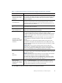
Typographical Conventions
The following conventions are used throughout the documentation:
Table 1.1 Typographical Conventions
Formatting
Informative Uses
User Interface text
Text you see in the User Interface (buttons, menus, etc.) and any
other interaction with the user interface are in bold-face.
References, terms
Cross-references and first use of acronyms and terms are in
italics.
Command line
File names, directories, and text displayed on the screen are
monospaced.
User input
User input on screen is in monospaced bold-face.
Command parameters
Command parameter names are in monospaced italics.
We use the following ways to indicate important or additional information:
Note – Notes prevent commonly-made mistakes by pointing out important points.
Caution – Cautions prevent breaches of security, information loss, or system downtime.
Cautions always contain critical information that you must observe.
Tip – Tips provide additional helpful information, such as alternative ways to complete steps.
Example Examples present a concrete scenario that clarifies the points made in the adjacent text.
10
Chapter 1
Using SMC Documentation
Documentation Available
SMC documentation is divided into two main categories: Product Documentation and Support
Documentation (page 12). Each SMC product has a separate set of manuals.
Product Documentation
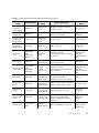
The table below lists the available product documentation.
Table 1.2 Product Documentation
Guide
Description
Reference Guide
Explains the operation and features of the SMC comprehensively.
Demonstrates the general workflow and provides example scenarios
for each feature area. Available as separate guides for McAfee
Security Management Center and McAfee Firewall/VPN, and as a
combined guide for McAfee IPS and McAfee Layer 2 Firewall.
Installation Guide
Instructions for planning, installing, and upgrading the SMC.
Available as separate guides for McAfee®Security Management
Center and McAfee Firewall/VPN, and as a combined guide for
McAfee IPS and McAfee Layer 2 Firewall.
Online Help
Describes how to configure and manage the system step-by-step.
Accessible through the Help menu and by using the Help button or
the F1 key in any window or dialog. Available in the Management
Client and the Web Portal. An HTML-based system is available in the
SSL VPN Administrator through help links and icons.
Administrator’s Guide
Describes how to configure and manage the system step-by-step.
Available as a combined guide for McAfee Firewall/VPN, McAfee IPS,
and McAfee Layer 2 Firewall, and as separate guides for the SSL
VPN and the IPsec VPN Client.
User’s Guide
Instructions for end-users. Available for the IPsec VPN Client and the
Web Portal.
Appliance Installation Guide
Instructions for physically installing and maintaining McAfee NGFW
appliances (rack mounting, cabling, etc.). Available for all McAfee
NGFW appliances.
PDF guides are available at https://www.stonesoft.com/en/customer_care/documentation/
current/. The McAfee SMC Administrator’s Guide, and the Reference Guides and Installation
Guides for McAfee Security Management Center, McAfee Firewall/VPN, McAfee IPS, and McAfee
Layer 2 Firewall are also available as PDFs on the Security Management Center DVD.
Documentation Available
11
Support Documentation
The McAfee support documentation provides additional and late-breaking technical information.
These technical documents support the SMC guide books, for example, by giving further
examples on specific configuration scenarios.
The latest technical documentation is available http://www.stonesoft.com/en/customer_care/
support/.
System Requirements
The certified platforms for running McAfee NGFW engine software can be found at the product
pages at http://www.stonesoft.com/en/products/ips/Software_Solutions/.
The hardware and software requirements for the version you are running can also be found in
the Release Notes available at http://www.stonesoft.com/en/customer_care/kb/.
Supported Features
Not all features are supported on all platforms. See the Appliance Software Support Table for
more information.
Contact Information
For general information about SMC products, visit our web site at http://www.mcafee.com/.
12
Chapter 1
Using SMC Documentation
P REPARING FOR
I NSTALLATION
In this section:
Planning the Installation - 15
Installing Licenses - 23
Configuring NAT Addresses - 27
13
14
C H A P TE R 2
PLANNING
THE I NSTALLATION
This chapter provides important information to take into account before the installation can
begin. The chapter also includes an overview to the installation process.
The following sections are included:
Introduction to McAfee IPS and Layer 2 Firewall (page 16)
Example Network Scenario (page 17)
Overview to the Installation Procedure (page 18)
Important to Know Before Installation (page 19)
15
Introduction to McAfee IPS and Layer 2 Firewall
A McAfee IPS or Layer 2 Firewall system consists of the McAfee Security Management Center
(SMC) and one or more IPS engines and/or Layer 2 Firewall engines, and one or more Master
Engines, Virtual IPS engines and/or Virtual Layer 2 Firewall engines. IPS engines, Layer 2
Firewalls, Virtual IPS engines, and Virtual Layer 2 Firewalls pick up network traffic, inspect it,
and create event data for further processing by the Log Server.
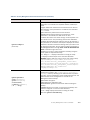
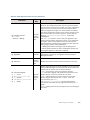
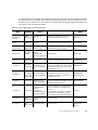
The following table describes the installation modes for IPS engines, Layer 2 Firewalls, and
Master Engines that host Virtual IPS engines or Virtual Layer 2 Firewalls.
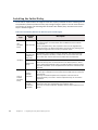
Table 2.1 Installation Modes for IPS Engines and Layer 2 Firewalls
NGFW Role
Mode
Inline
In an inline installation, the traffic flows through the IPS engine.
The IPS engine has full control over the traffic flow and can be
used to automatically block any traffic. An inline IPS engine can
also enforce blacklisting commands received from other
components. Fail-open network cards can be used to ensure
traffic flow is not disrupted when the IPS engine is offline. An
inline IPS engine also provide access control and logging for any
Ethernet traffic (layer 2).
Capture
In a capture installation, external equipment duplicates the
traffic flow for inspection, and the IPS engine just “listens in”.
The IPS engine does not have direct control over the traffic flow,
but it can respond to selected threats by sending packets that
reset the connections. An IDS-only IPS engine can send
blacklisting requests to other IPS engines, Layer 2 Firewalls, or
Firewalls, but it cannot enforce blacklisting requests from other
components.
Inline
In an inline installation, the traffic flows through the Layer 2
Firewall. The Layer 2 Firewall has full control over the traffic flow
and can be used to automatically block any traffic. An inline
Layer 2 Firewall can also enforce blacklisting commands received
from other components. An inline Layer 2 Firewall also provides
access control and logging for any Ethernet traffic (layer 2).
Capture
(Passive
Firewall)
In a capture (Passive Firewall) installation, external equipment
duplicates the traffic flow for inspection to the Layer 2 Firewall,
and the Layer 2 Firewall just “listens in”. The Layer 2 Firewall
does not have direct control over the traffic flow, but it can
respond to selected threats by sending packets that reset the
connections. A Layer 2 Firewall in Passive Firewall mode can
send blacklisting requests to other Layer 2 Firewalls, IPS
engines, or Firewalls, but it cannot enforce blacklisting requests
from other components.
IPS
Layer 2 Firewall
16
Chapter 2
Description
Planning the Installation
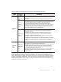
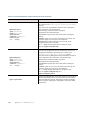
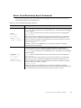
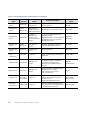
Table 2.1 Installation Modes for IPS Engines and Layer 2 Firewalls (Continued)
NGFW Role
Layer 2 Firewall
(cont.)
Mode
Description
Passive Inline
In a passive inline installation, the traffic flows through the Layer
2 Firewall, but the Layer 2 Firewall is configured to only log
connections. A Layer 2 Firewall in Passive Firewall mode can
send blacklisting requests to other Layer 2 Firewalls, IPS
engines, or Firewalls, but it cannot enforce blacklisting requests
from other components.
The main features of McAfee IPS and Layer 2 Firewall include:
• Multiple detection methods: misuse detection uses fingerprints to detect known attacks.
Anomaly detection uses traffic statistics to detect unusual network behavior. Protocol
validation identifies violations of the defined protocol for a particular type of traffic. Event
correlation processes event information to detect a pattern of events that might indicate an
intrusion attempt.
• Response mechanisms: There are several response mechanisms to anomalous traffic. These
include different alerting channels, traffic recording, TCP connection termination, traffic
blacklisting, and traffic blocking with Inline Interfaces.
The IPS engines, Layer 2 Firewalls, Master Engines, Virtual IPS engines, and Virtual Layer 2
Firewalls are managed centrally through the SMC. You must have an SMC configured before you
can proceed with installing the engines. The SMC installation is covered in a separate guide.
See the McAfee SMC Reference Guide for more background information on the SMC, and the
McAfee NGFW Reference Guide for IPS and Layer 2 Firewall Roles for more background
information on IPS engines and Layer 2 Firewalls.
Example Network Scenario
To get a better understanding of how McAfee IPS and Layer 2 Firewall fit into a network, you can
consult the Example Network Scenario that shows you one way to deploy the system. See
Example Network Scenario (page 157).
Example Network Scenario
17
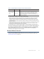
Overview to the Installation Procedure
1. Check the surrounding network environment as explained in Capture Interfaces (page 19).
2. Install licenses for the engines. See Installing Licenses (page 23).
3. If network address translation (NAT) is applied to communications between SMC
components and the engines, define Contact Addresses. See Configuring NAT Addresses
(page 27).
4. Define the IPS and/or Layer 2 Firewall element(s) in the Management Client. See Defining
IPS Engines (page 33) and Defining Layer 2 Firewalls (page 43).
5. Define the Master Engine element(s) and Virtual IPS and/or Virtual Layer 2 Firewall
element(s) in the Management Client. See Configuring Master Engines and Virtual IPS
Engines (page 53) and Configuring Master Engines and Virtual Layer 2 Firewalls
(page 67).
6. Generate the initial configuration for the IPS engine(s), Layer 2 Firewall engine(s), and/or
Master Engine(s). See Saving the Initial Configuration (page 83). No initial configuration is
needed for Virtual IPS engines or Virtual Layer 2 Firewalls.
7. Install and configure the IPS engine(s), Layer 2 Firewall engine(s), and/or Master
Engine(s).
• For hardware installation and initial configuration of McAfee NGFW appliances, see the
Appliance Installation Guide that is delivered with each appliance.
• For software installations, see Installing the Engine on Other Platforms (page 97).
• No installation is needed for Virtual IPS engines and Virtual Layer 2 Firewalls.
8. Configure routing and install a policy on the engine(s). See Configuring Routing and
Installing Policies (page 89). No routing is needed for Virtual IPS engines or Virtual Layer
2 Firewalls.
The chapters and sections of this guide proceed in the order outlined above.
18
Chapter 2
Planning the Installation
Important to Know Before Installation
Before you start the installation, you need to carefully plan the site that you are going to install.
Consult the McAfee NGFW Reference Guide for IPS and Layer 2 Firewall Roles if you need more
detailed background information on the operation of the system than what is offered in this
chapter.
Supported Platforms
IPS engines and Layer 2 Firewalls can be run on the following general types of platforms:
• Purpose-built McAfee NGFW appliances.
• Standard Intel-compatible servers. Search for the version-specific Hardware Requirements in
the technical documentation search at http://www.stonesoft.com/en/customer_care/kb/.
• Virtualization platforms that support the deployment of Open Virtual Format (OVF) templates.
VMWare is officially supported. Other virtualization platforms may also be supported. There
are some additional requirements and limitations when the IPS engine or Layer 2 Firewall is
installed on a virtualization platform. See the Release Notes available at
http://www.stonesoft.com/en/customer_care/kb/ for more information. Detailed
instructions can be found in Installing the Engine on a Virtualization Platform (page 101).
The engines have an integrated, hardened Linux operating system that is always a part of the
McAfee NGFW engine software, eliminating the need for separate operating system installation,
configuration, and patching.
Date and Time Settings
The time settings of the engines do not need to be adjusted, as they are automatically
synchronized to the Management Server’s time setting. For this operation, the time is converted
to UTC time according to the Management Server’s time zone setting.
Capture Interfaces
IPS engines can be connected to a switch SPAN port or a network TAP to capture network traffic.
The considerations for these connection methods are explained below. Additionally, the IPS
engine can be installed inline, so that the network traffic flows through the engine, allowing
active blocking of any connection.
Layer 2 Firewalls are usually installed inline to inspect and block traffic. They can also be
configured in Passive Firewall mode, either by connecting the Layer 2 Firewall to a switch SPAN
port to capture network traffic or by setting the engine to only log connections in an inline
configuration.
For more specific information on compatibility of different network devices and McAfee IPS
engines and Layer 2 Firewalls, see http://www.stonesoft.com/support/.
Important to Know Before Installation
19
Switch SPAN Ports
A Switched Port Analyzer (SPAN) port is used for capturing network traffic to a defined port on a
switch. This is also known as port mirroring. The capturing is done passively, so it does not
interfere with the traffic.
An IPS engine’s or Layer 2 Firewall’s Capture Interface can be connected directly to a SPAN port
of a switch. All the traffic to be monitored must be copied to this SPAN port.
Network TAPs
A Test Access Port (TAP) is a passive device located at the network wire between network
devices. The capturing is done passively, so it does not interfere with the traffic. With a network
TAP, the two directions of the network traffic is divided to separate wires. For this reason, the IPS
engine needs two Capture Interfaces for a network TAP; one Capture Interface for each direction
of the traffic. The two related Capture Interfaces must have the same Logical Interface that
combines the traffic of these two interfaces for inspection. You could also use the pair of
Capture Interfaces to monitor traffic in two separate network devices.
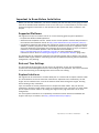
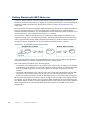
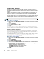
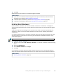
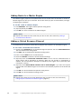
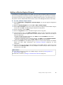
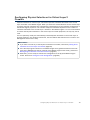
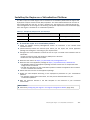
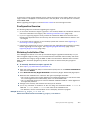
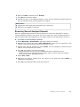
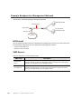
Cabling Guidelines
Follow standard cabling with inline IPS engines and Layer 2 Firewalls:
• Use straight cables to connect the Layer 2 Firewalls and IPS engines to switches.
• Use crossover cables to connect the Layer 2 Firewalls and IPS engines to hosts (such as
routers or Firewalls).
Note – Fail-open network interface cards support Auto-MDIX, so both crossover and straight
cables may work when the IPS engine is online. However, only the correct type of cable
allows traffic to flow when the IPS engine is offline and the fail-open network interface
card is in bypass state. It is recommended to test the IPS deployment in offline state to
make sure that the correct cables are used.
Also, make sure the copper cables are correctly rated (CAT 5e or CAT 6 in gigabit networks).
Cabling for Master Engines that host Virtual IPS engines or Virtual Layer 2 Firewalls follows the
same principles as the cabling for inline IPS engines and Layer 2 Firewalls.
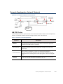
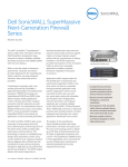
Illustration 2.1 Correct Cable Types for Single IPS Engines
Switch
Switch
Straight cable
Straight cable
Single IPS Engine
Crossover cable
Host/Firewall
20
Chapter 2
Planning the Installation
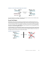
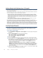
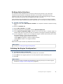
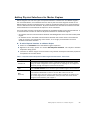
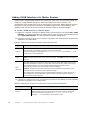
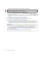
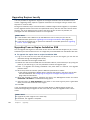
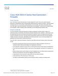
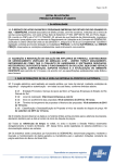
Straight cable
Switch
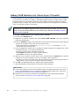
Illustration 2.2 Correct Cable Types for Single Layer 2 Firewalls
Switch
Switch
Straight cable
Crossover cable
Straight cable
Single Layer 2
Firewall
Straight cable
Switch
Host/Firewall
For more information on cabling for IPS engines and Layer 2 Firewalls, see the McAfee NGFW
Reference Guide for IPS and Layer 2 Firewall Roles.
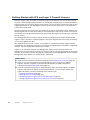
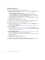
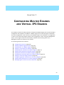
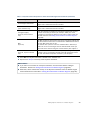
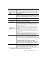
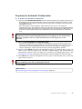
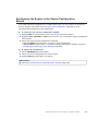
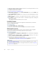
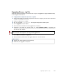
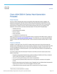
Speed And Duplex
Mismatched speed and duplex settings are a frequent source of networking problems. The
basic principle for speed and duplex settings is that network cards at both ends of each cable
must have identical settings. This principle also applies to the automatic negotiation setting: if
one end of the cable is set to autonegotiate, the other end must also be set to autonegotiate
and not to any fixed setting. Gigabit standards require interfaces to use autonegotiation. Fixed
settings are not allowed at gigabit speeds.
For Inline Interfaces, the settings must be identical on both links within each Inline Interface pair
(identical settings on all four interfaces) instead of just matching settings at both ends of each
cable (two + two interfaces). If one of the links has a lower maximum speed than the other link,
the higher-speed link must be set to use the lower speed.
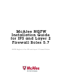
Illustration 2.3 Speed/Duplex Settings
100/Full
100/Full
Correct
100/Full
Incorrect
1000/Full
Important to Know Before Installation
21
22
Chapter 2
Planning the Installation
C H A P TE R 3
INSTALLING LICENSES
This chapter instructs how to generate and install licenses for IPS engines, Layer 2 Firewalls,
and Master Engines.
The following sections are included:
Getting Started with IPS and Layer 2 Firewall Licenses (page 24)
Generating New Licenses (page 25)
Installing Licenses (page 26)
23
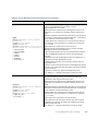
Getting Started with IPS and Layer 2 Firewall Licenses
Each IPS engine, Layer 2 Firewall, and Master Engine must have its own license. IPS engines
may use a Security Engine Node license or an IPS-specific license. Layer 2 Firewalls and Master
Engines always use a Security Engine Node license. The correct type of license for each engine
is generated based on your Management Server proof-of-license (POL) code or the appliance
proof-of-serial (POS) code.
Virtual IPS engines and Virtual Layer 2 Firewalls do not require a separate license. However, the
Master Engine license limits the number of Virtual Resources that can be created. The limit for
the number of Virtual Resources limits how many Virtual IPS engines or Virtual Layer 2 Firewalls
can be created.
The Management Server’s license may be limited to managing only a certain number of IPS
engines, Layer 2 Firewalls, or Master Engines. Virtual IPS engines and Virtual Layer 2 Firewalls
do not count against this limit.
With appliances version 5.0 or newer, it is possible to download and install engine licenses
automatically. For additional information on automatic downloading and installation of appliance
licenses, see the McAfee SMC Administrator’s Guide.
If there is no connection between the Management Server and the License Center, the
appliance can be used without a license for 30 days. After this you must generate the license(s)
manually at the License Center web page and install them on the Management Server using the
Management Client before your system is fully operational.
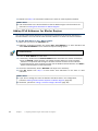
What’s Next?
If you need new licenses, proceed as explained in the Configuration Overview (page 25).
If you do not need new licenses for the IPS engines, Layer 2 Firewalls, or Master
Engines, and NAT is applied to communications between any SMC components,
proceed to Configuring NAT Addresses (page 27).
If you do not need new licenses for the IPS engines, Layer 2 Firewall engines, or Master
Engines, and NAT is not applied to the communications, you are ready to define the
engine element(s). Continue according to the element type:
• Defining IPS Engines (page 33)
• Defining Layer 2 Firewalls (page 43)
• Configuring Master Engines and Virtual IPS Engines (page 53)
• Configuring Master Engines and Virtual Layer 2 Firewalls (page 67)
24
Chapter 3
Installing Licenses
Configuration Overview
The following steps are needed for installing licenses for IPS engines, Layer 2 Firewall engines,
and Master Engines.
1. Generate the licenses. See Generating New Licenses.
2. Install the licenses in the Management Client. See Installing Licenses (page 26).
Generating New Licenses
You generate the licenses based on your Management Server POL code, or the appliance POS
code. Evaluation licenses are also available.
Note – Evaluation license requests may need manual processing. See the license page for
current delivery times and details.
If you are licensing several components of the same type, remember to generate one license for
each component.
To generate a new license
1. Go to my.stonesoft.com/managelicense.do.
2. Enter the required code (POL or POS) in the License Identification field and click Submit.
The License Center page opens.
• The proof-of-license (POL) code identifies a license. You can find it in the order delivery
message (usually sent by e-mail). Later on, this information is shown in the Licenses
branch of the Administration Configuration view in the Management Client.
• McAfee NGFW appliances additionally have a proof-of-serial number (POS) that you can
find on a label attached to the appliance hardware.
3. Click Register. The License Generation page opens.
4. Enter the Management Server’s POL code or the appliance POS code for the engines you
want to license.
5. Click Submit Request. The license file is sent to you in a moment. It also becomes
available for download at the license page.
Generating New Licenses
25
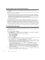
Installing Licenses
To install licenses, the license files must be available to the computer you use to run the
Management Client.
Note – You can install all of the licenses even though you have not yet defined all the
elements the licenses will be bound to.
To install licenses
1. Select File→System Tools→Install Licenses.
2. Select one or more license files in the dialog that opens and click Install.
To check that the licenses were installed correctly
1. Select Configuration→Configuration→Administration. The Administration Configuration
view opens.
2. Browse to Licenses→Security Engines or Licenses→IPS depending on the type of
licenses you have.
You should see one license for each IPS engine, Layer 2 Firewall engine, or Master Engine node.
If you have Management Server POL-bound engine licenses, you must bind them manually to the
correct engines once you have configured the engine elements.
What’s Next?
If NAT is applied to communications between SMC components, proceed to Configuring
NAT Addresses (page 27).
Otherwise, you are ready to define the engine element(s). Continue according to the
element type:
• Defining IPS Engines (page 33)
• Defining Layer 2 Firewalls (page 43)
• Configuring Master Engines and Virtual IPS Engines (page 53)
• Configuring Master Engines and Virtual Layer 2 Firewalls (page 67)
26
Chapter 3
Installing Licenses
C H A P TE R 4
CONFIGURING NAT ADDRESSES
This chapter contains the steps needed to configure Locations and contact addresses when a
NAT (network address translation) operation is applied to the communications between the
Security Engine and other SMC components.
The following sections are included:
Getting Started with NAT Addresses (page 28)
Defining Locations (page 29)
Adding SMC Server Contact Addresses (page 30)
27
Getting Started with NAT Addresses
If there is network address translation (NAT) between communicating SMC components, the
translated IP address may have to be defined for system communications. All communications
between the SMC components are presented as a table in Default Communication Ports
(page 149).
You use Location elements to configure SMC components for NAT. There is a Default Location to
which all elements belong if you do not assign them a specific Location. If NAT is applied
between two SMC components, you must separate them into different Locations and then add a
contact address for the component that needs to be contacted.
You can define a Default contact address for contacting an SMC component (defined in the
Properties dialog of the corresponding element). The component’s Default contact address is
used in communications when SMC components that belong to another Location contact the
component and the component has no contact address defined for their Location.
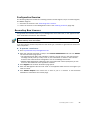
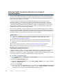
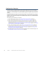
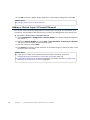
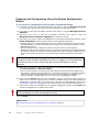
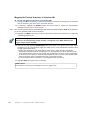
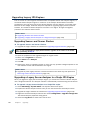
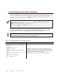
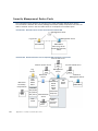
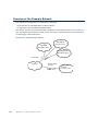
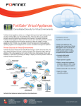
Illustration 4.1 An Example Scenario for Using Locations
Headquarters Location
Intranet
Management/
Log Server
Branch Office Location
Intranet
Internet
IPS
Firewall
Firewall
IPS
In the example scenario above, the same Management Server and Log Server manage SMC
components both at a company’s headquarters and in a branch office.
NAT could typically be applied at the following points:
• The Firewall at the headquarters or an external router may provide the SMC servers external
IP addresses on the Internet. The external addresses must be defined as contact addresses
so that the SMC components at the branch offices can contact the servers across the
Internet.
• The branch office Firewall or an external router may provide external addresses for the SMC
components at the branch office. Also in this case, the external IP addresses must be
defined as contact addresses so that the Management Server can contact the components.
When contact addresses are needed, it may be enough to define a single new Location element,
for example, for the branch office, and to group the SMC components at the branch office into
the “Branch Office” Location. The same Location element could also be used to group together
SMC components at any other branch office when they connect to the SMC servers at the
headquarters.
28
Chapter 4
Configuring NAT Addresses
Configuration Overview
To add contact addresses, proceed as follows:
1. Define Location element(s). See Defining Locations.
2. Define contact addresses for the Management Server and Log Server(s). See Adding SMC
Server Contact Addresses (page 30).
3. Select the correct Location for the engines when you create the IPS and Layer 2 Firewall
elements. See Defining IPS Engines (page 33) and Defining Layer 2 Firewalls (page 43).
Defining Locations
The first task is to group the SMC components into Location elements based on which
components are on the same side of a NAT device. The elements that belong to the same
Location element always use the primary IP address (defined in the Properties dialog of the
element) when contacting each other.
To create a new Location element
1. Select Configuration→Configuration→Administration. The Administration Configuration
view opens.
2. Expand Other Elements in the tree view.
3. Right-click Locations and select New Location. The Location Properties dialog opens.
4. Type in a Name.
5. Select the element(s) that belong to the Location and click Add.
6. Click OK.
Repeat to add other Locations as necessary.
What’s Next?
If your Management Server or Log Server needs a contact address, proceed to Adding
SMC Server Contact Addresses (page 30).
If you plan to add contact addresses only for IPS or Layer 2 Firewall elements, proceed
to Defining IPS Engines (page 33) or Defining Layer 2 Firewalls (page 43).
Defining Locations
29
Adding SMC Server Contact Addresses
The Management Server and the Log Server can have more than one contact address for each
Location. This allows you, for example, to define a contact address for each Internet link in a
Multi-Link configuration for remotely managed components.
To define the Management Server and Log Server contact addresses
1. Select Configuration→Configuration→Security Engine. The Security Engine Configuration
view opens.
2. Expand the Network Elements branch and select Servers.
3. Right-click a server and select Properties. The Properties dialog for that server opens.
4. Select the Location of this server.
5. Enter the Default contact address. If the server has multiple alternative IP addresses,
separate the addresses with commas.
6. Click Exceptions and define Location-specific contact addresses if the Default Contact
Address(es) are not valid from all other Locations.
Note – Elements grouped in the same Location element always use the primary IP address
(defined in the Properties dialog of the element) when contacting each other. All elements
not specifically put in a certain Location are treated as if they belonged to the same
Location.
7. Click OK to close the server properties and define the contact addresses for other servers
in the same way.
What’s Next?
Defining IPS Engines (page 33)
Defining Layer 2 Firewalls (page 43)
30
Chapter 4
Configuring NAT Addresses
C ONFIGURING E NGINES
In this section:
Defining IPS Engines - 33
Defining Layer 2 Firewalls - 43
Configuring Master Engines and Virtual IPS Engines - 53
Configuring Master Engines and Virtual Layer 2 Firewalls - 67
Saving the Initial Configuration - 83
Configuring Routing and Installing Policies - 89
31
32
C H A P TE R 5
DEFINING IPS ENGINES
This chapter contains the steps needed to complete the IPS engine configuration that
prepares the SMC for IPS engine installation.
Very little configuration is done directly on the engines. Most of the configuration is done
using the Management Client, so the engines cannot be successfully installed before defining
them in the SMC as outlined in this chapter.
The following sections are included:
Getting Started with Defining IPS Engines (page 34)
Creating Engine Elements (page 34)
Defining System Communication Interfaces for IPS Engines (page 35)
Setting Interface Options for IPS Engines (page 37)
Defining Traffic Inspection Interfaces for IPS Engines (page 38)
Bypassing Traffic on Overload (page 42)
Finishing the Engine Configuration (page 42)
33
Getting Started with Defining IPS Engines
The IPS engine elements are a tool for configuring nearly all aspects of your physical IPS
components.
An important part of the IPS engine elements are the interface definitions. There are two main
categories of IPS engine interfaces:
• Interfaces for system communications. These are used when the IPS engine is the source or
the final destination of the communications (for example, in system communications between
the IPS engine and the Management Server). You must define at least one interface that is
dedicated to system communications for each IPS engine element.
• Interfaces for inspecting traffic. You must define one or more traffic inspection interfaces for
each IPS engine element.
The interfaces have their own numbering in the SMC called Interface ID. The numbering is
independent of the operating system interface numbering on the engines. However, if you do the
engine’s initial configuring using the automatic USB memory stick configuration method, the
Interface IDs in the SMC are mapped to match the Physical Interface numbering in the operating
system (eth0 is mapped to Interface ID 0 and so on). If you do the initial configuration manually,
you can freely choose how the Interface IDs in the SMC are mapped to the Physical Interfaces.
Creating Engine Elements
This section covers the basic configuration of IPS engine elements. For complete instructions on
configuring IPS engine properties, see the Management Client Online Help or the McAfee SMC
Administrator’s Guide.
To create an engine element
1. Select Configuration→Configuration→Security Engine. The Security Engine Configuration
view opens.
2. Right-click Security Engines and select one of the following:
• New→IPS→IPS Cluster
• New→IPS→Single IPS
3. Enter a unique Name.
4. Select the Log Server that stores the log events that the IPS engine creates. If no Log
Server is selected, the engine does not make any traffic recordings.
5. (Optional) Define one or more DNS IP Addresses for the IPS engine. These are the IP
addresses of the DNS server(s) that the IPS engine uses to resolve domain names and web
filtering categorization services (which are defined as URLs).
• To enter a single IP address manually, click Add and select IP Address. Enter the IP
address in the dialog that opens.
• To define an IP address by using a Network element, click Add and select Network
Element. Select a predefined Alias element that represents the IP address of the DNS for
a dynamic network interface, a Host element, or an External DNS Server element from
the dialog that opens, or click the New icon and select Host or External DNS Server to
define a new element.
6. Select the correct Location for this engine if there is a NAT device between SMC
components affecting this IPS engine’s communications.
34
Chapter 5
Defining IPS Engines
Defining System Communication Interfaces for IPS
Engines
Each IPS engine needs at least one interface for communicating with other SMC components.
More than one system communication interface can be added to provide a primary and a
backup interface for Management Server communications.
Defining Physical Interfaces
To define a Physical Interface
1. Switch to the Interfaces tab.
2. Right-click and select New Physical Interface. The Physical Interface Properties dialog
opens.
3. Select the Interface ID.
4. Select Normal Interface as the Type.
5. Click OK.
The Physical Interface is added to the interface list. Add the necessary number of interfaces in
the same way.
What’s Next?
If you want to add VLANs to the Physical Interface, continue by Defining VLAN Interfaces.
Otherwise, continue by Defining IP Addresses (page 36).
Defining VLAN Interfaces
VLANs divide a single physical network link into several virtual links. You can add up to 4094
VLANS per interface.
Caution – Do not add any manual VLAN definitions to an interface you want to use for
sending resets. Adding VLANs prevents selecting the interface as a Reset Interface and
also removes the Reset Interface from any existing selections.
To define a VLAN Interface
1. Right-click a Physical Interface and select New→VLAN Interface. The VLAN Interface
Properties dialog opens.
2. Enter the VLAN ID (1-4094).
Note – The VLAN ID must be the same VLAN ID used in the switch at the other end of the
VLAN trunk.
3. Click OK. The specified VLAN ID is added to the Physical Interface.
Repeat the steps above to add further VLANs to the interface.
The VLAN Interface is now ready to be used as a network interface. The VLAN Interface is
identified as Interface-ID.VLAN-ID, for example 2.100 for Interface ID 2 and VLAN ID 100.
Defining System Communication Interfaces for IPS Engines
35
Defining IP Addresses
To define an IP address for a single IPS
1. Right-click a Physical Interface or a VLAN Interface and select New→IPv4 Address. The IP
Address Properties dialog opens.
2. Configure the IP address information.
• Enter the IPv4 Address and Network Settings to define a static IP address.
• Select the Dynamic option (top right) and the DHCP index if the interface gets its IP
address from a DHCP server. The DHCP Index is an arbitrary number of your choice that
distinguishes different DHCP interfaces from one another.
3. If NAT is applied to system communications, enter a Contact Address to define the
translated IP address of this engine.
4. Click OK to close the IP Address Properties dialog.
You can define several IP addresses for the same Physical Interface or VLAN Interface. Before
you continue, write down the networks to which each Interface ID is connected.
To define IP addresses for an IPS cluster
1. Right-click a Physical Interface or a VLAN Interface and select New→IPv4 Address. The IP
Address Properties dialog opens.
2. Double-click the IPv4 Address cell and enter the IPv4 address. Repeat for each node.
3. Enter the Netmask.
4. If NAT is applied to system communications, double-click the Contact Address cell and
continue as explained in To define a contact address (page 36). Otherwise, click OK to
close the IP Address Properties dialog.
To define a contact address
1. Enter the Default contact address to define the translated IP address of this engine. This
address is used by default by components in a different Location.
2. (Optional) Click Add to define a different contact address for contacting this engine from
some specific Location.
3. Click OK to close the Contact Addresses dialog.
4. Click OK to close the IP Address Properties dialog.
You can define several IP addresses for the same Physical Interface or VLAN Interface. Before
you continue, write down the networks to which each Interface ID is connected.
36
Chapter 5
Defining IPS Engines
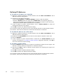
Setting Interface Options for IPS Engines
Interface options allow you to select which interfaces are used for which types of system
communications.
To set the Interface Options
1. Click Options. The Interface Options dialog opens.
2. Select the Primary Control IP address for communications with the Management Server.
3. (Optional) Select a Backup Control IP address for Management Server contact (used if the
Primary fails).
4. (IPS Cluster only) Select the Primary Heartbeat Interface for communications between the
nodes of the cluster. This must not be a VLAN Interface.
Caution – Heartbeat traffic is time-critical. A dedicated network (without other traffic) is
strongly recommended for security and reliability of heartbeat communication.
5. (IPS Cluster only, recommended) Select a second Physical Interface as the Backup
Heartbeat Interface.
6. (Single IPS only) Select Node-initiated contact to Management Server if the IPS engine is
behind a device that applies dynamic NAT to the inbound management connections or
blocks them.
7. Select the Default IP Address for outgoing traffic.
8. Click OK.
Setting Interface Options for IPS Engines
37
Defining Traffic Inspection Interfaces for IPS Engines
IPS engines pick up passing network traffic for inspection in real time. The traffic can either be
captured for inspection through the engine’s Capture Interfaces, or it can be inspected as it
flows through the engine’s Inline Interfaces. You can define both Capture Interfaces and Inline
Interfaces for the same IPS engine.
An IPS engine can actively filter only traffic that attempts to pass through its Inline Interfaces.
However, it can reset traffic picked up through Capture Interfaces if you set up specific Reset
Interfaces. The Reset Interfaces can send TCP resets and ICMP “destination unreachable”
messages when the communications trigger a response. You can use a system communications
interface for sending resets if the resets are routed correctly through that interface and there
are no VLANs on the interface.
When traffic is inspected, it may be important to know the interface through which it arrives to
the IPS engine. It is also important to be able to distinguish an IPS engine’s Capture Interfaces
from its Inline Interfaces. Logical Interface elements are used for both these purposes. They
allow you to group together interfaces that belong to the same network segment and to identify
the type of the traffic inspection interface (Capture Interface or Inline Interface).
What’s Next?
If you want to create both Capture and Inline Interfaces on the same IPS engine, or if
you want to create Logical Interfaces to distinguish interfaces from each other, proceed
to Defining Logical Interfaces (page 39).
If you do not want to use an existing system communication interface as the Reset
Interface, define the new Reset Interfaces as instructed in Defining Reset Interfaces
(page 40).
To define Capture Interfaces, proceed to Defining Capture Interfaces (page 40).
To define Inline Interfaces, proceed to Defining Inline Interfaces (page 41).
38
Chapter 5
Defining IPS Engines
Defining Logical Interfaces
A Logical Interface is used in the IPS policies and the traffic inspection process to represent a
network segment. The SMC contains one default Logical Interface. A Logical Interface can
represent any number or combination of interfaces and VLAN Interfaces, except that the same
Logical Interface cannot be used to represent both Capture Interfaces and Inline Interfaces on
the same IPS engine. The rules in the ready-made IPS Template match all Logical Interfaces.
To define a Logical Interface
1. Select Configuration→Configuration→Security Engine. The Security Engine Configuration
view opens.
2. Expand the Other Elements branch.
3. Right-click Logical Interfaces and select New Logical Interface. The Logical Interface
Properties dialog opens.
4. Enter a unique Name.
5. (Optional) If you use VLAN tagging on Capture or Inline Interfaces, select View interface as
one LAN if you do not want the IPS engine to see a single connection as multiple
connections when a switch passes traffic between different VLANs and all traffic is mirrored
to the IPS engine through a SPAN port.
6. Click OK.
Repeat these steps to define any additional Logical Interfaces.
What’s Next?
If you want to use Reset Interfaces together with Capture Interfaces, define the Reset
Interfaces first. Proceed to Defining Reset Interfaces (page 40).
To define Capture Interfaces, proceed to Defining Capture Interfaces (page 40).
To define Inline Interfaces, proceed to Defining Inline Interfaces (page 41).
Defining Traffic Inspection Interfaces for IPS Engines
39
Defining Reset Interfaces
Reset Interfaces can deliver TCP resets and ICMP “destination unreachable” messages to
interrupt communications picked up from Capture Interfaces when the communications trigger a
response.
VLANs are supported for sending resets, but the correct VLAN is selected automatically. An
interface you want to use as the Reset Interface must not have any manually added VLAN
configuration.
The Reset Interface must be in the same broadcast domain as the Capture Interface that uses
the Reset Interface. The resets are sent using the IP addresses and MAC addresses of the
communicating hosts.
Note – An interface that is used only as a Reset Interface must not have an IP address.
To define a Reset Interface
1. Right-click and select New Physical Interface. The Physical Interface Properties dialog
opens.
2. Select the Interface ID.
3. Select Normal Interface as the Type.
4. Click OK.
This interface can now be used as a Reset Interface. When you set up the physical network,
make sure that the Reset Interface connects to the same network as the Capture Interface(s).
Defining Capture Interfaces
Capture Interfaces listen to traffic that is not routed through the IPS engine. You can have as
many Capture Interfaces as there are available physical ports on the IPS engine (there are no
license restrictions regarding this interface type).
External equipment must be set up to mirror traffic to the Capture Interface. You can connect a
Capture Interface to a switch SPAN port or a network TAP to capture traffic. For more
information, see Capture Interfaces (page 19).
To define a Capture Interface
1. Right-click and select New Physical Interface. The Physical Interface Properties dialog
opens.
2. Select the Interface ID.
3. Select Capture Interface as the Type.
4. (Optional) Select a TCP Reset Interface for traffic picked up through this Capture Interface.
5. If your configuration requires you to change the Logical Interface from Default_Eth, select
the Logical Interface in one of the following ways:
• Select an existing Logical Interface from the list.
• Select Other and browse to another Logical Interface.
• Select New to create a new Logical Interface.
6. Click OK.
40
Chapter 5
Defining IPS Engines
Repeat these steps to define any additional Capture Interfaces.
What’s Next?
To define Inline Interfaces, proceed to Defining Inline Interfaces.
To define how an inline IPS engine handles traffic when the traffic load is too high,
proceed to Bypassing Traffic on Overload (page 42).
Otherwise, proceed to Finishing the Engine Configuration (page 42).
Defining Inline Interfaces
The number of Inline Interfaces you can have are limited by the license in use. One Inline
Interface always comprises two Physical Interfaces, as the traffic is forwarded from one
interface to the other. The allowed traffic passes through as if it was going through a network
cable. The traffic you want to stop is dropped by the IPS engine.
Inline Interfaces (like Capture Interfaces) are associated with a Logical Interface, which is used
in the IPS policies and the traffic inspection process to represent one or more IPS engine
interfaces.
Fail-open network cards have fixed pairs of ports. Take particular care to map these ports
correctly during the initial configuration of the engine. Otherwise, the network cards do not
correctly fail open when the IPS engine is offline. If you use the automatic USB memory stick
configuration method for the engine’s initial configuration, the ports are configured
automatically. See Configuring the Engine Automatically with a USB Stick (page 102) for more
information.
To define an Inline Interface
1. Right-click and select New Physical Interface. The Physical Interface Properties dialog
opens.
2. Select the Interface ID.
3. Select Inline Interface as the Type.
4. (Optional) Change the automatically selected Second Interface ID.
5. Leave Inspect Unspecified VLANs selected if you want the IPS engine to inspect traffic
also from VLANs that are not included in the IPS engine’s interface configuration.
6. If your configuration requires you to change the Logical Interface from Default_Eth, select
the Logical Interface in one of the following ways:
• Select an existing Logical Interface from the list.
• Select Other and browse to another Logical Interface.
• Select New to create a new Logical Interface.
7. Click OK.
Repeat these steps to define any additional Inline Interfaces.
What’s Next?
To define how an inline IPS engine handles traffic when the load is too high, proceed to
Bypassing Traffic on Overload (page 42).
Otherwise, proceed to Finishing the Engine Configuration (page 42).
Defining Traffic Inspection Interfaces for IPS Engines
41
Bypassing Traffic on Overload
By default, inline IPS engines inspect all connections. If the traffic load is too high for the inline
IPS engine to inspect all the connections, some traffic may be dropped. Alternatively, inline IPS
engines can dynamically reduce the number of inspected connections if the load is too high.
This can improve performance in evaluation environments, but some traffic may pass through
without any access control or inspection.
Caution – Using Bypass mode requires a fail-open network interface card. If the ports that
represent the pair of Inline Interfaces cannot fail open, policy installation fails on the
engine. Bypass mode is not compatible with VLAN re-tagging. In network environments
where VLAN re-tagging is used, Normal mode is automatically enforced.
To bypass traffic on overload
1. Switch to the Advanced tab.
2. Select Bypass Traffic on Overload.
What’s Next?
Proceed to Finishing the Engine Configuration.
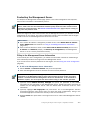
Finishing the Engine Configuration
To finish the engine configuration
1. Write down the networks to which each Interface ID is connected
2. Click OK close the engine properties. You are promoted to open the Routing view
3. Click No.
What’s Next?
You are now ready to transfer the configuration to the physical IPS engines. Proceed to
Saving the Initial Configuration (page 83).
42
Chapter 5
Defining IPS Engines
C H A P TE R 6
DEFINING LAYER 2 FIREWALLS
This chapter contains the steps needed to complete the Layer 2 Firewall engine configuration
that prepares the SMC for a McAfee Layer 2 Firewall engine installation.
Very little configuration is done directly on the engines. Most of the configuration is done
using the Management Client, so the engines cannot be successfully installed before defining
them in the SMC as outlined in this chapter.
The following sections are included:
Getting Started with Defining Layer 2 Firewalls (page 44)
Creating Engine Elements (page 44)
Defining System Communication Interfaces for Layer 2 Firewall Engines (page 45)
Setting Interface Options for Layer 2 Firewall Engines (page 47)
Defining Traffic Inspection Interfaces for Layer 2 Firewall Engines (page 48)
Finishing the Engine Configuration (page 51)
43
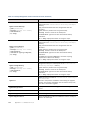
Getting Started with Defining Layer 2 Firewalls
The Layer 2 Firewall engine elements are a tool for configuring nearly all aspects of your physical
Layer 2 Firewall components.
An important part of the Layer 2 Firewall engine elements are the interface definitions. There are
three main categories of Layer 2 Firewall engine interfaces:
• Normal Interfaces for system communications. These are used when the Layer 2 Firewall
engine is the source or the final destination of the communications (for example, in control
communications between the Layer 2 Firewall engine and the Management Server). You must
define at least one interface that is dedicated to system communications for each Layer 2
Firewall engine element.
• Inline Interfaces and Capture Interfaces for inspecting traffic. You must define one or more
traffic inspection interfaces for each Layer 2 Firewall engine element.
The interfaces have their own numbering in the SMC called Interface ID. The numbering is
independent of the operating system interface numbering on the engines. However, if you do the
engine’s initial configuring using the automatic USB memory stick configuration method, the
Interface IDs in the SMC are mapped to match the Physical Interface numbering in the operating
system (eth0 is mapped to Interface ID 0 and so on). If you do the initial configuration manually,
you can freely choose how the Interface IDs in the SMC are mapped to the Physical Interfaces.
Creating Engine Elements
This section covers the basic configuration of Layer 2 Firewall engine elements. For complete
instructions on configuring Layer 2 Firewall engine properties, see the Management Client
Online Help or the McAfee SMC Administrator’s Guide.
To create an engine element
1. Select Configuration→Configuration→Security Engine. The Security Engine Configuration
view opens.
2. Right-click Security Engines and select one of the following:
• New→Layer 2 Firewall→Layer 2 Firewall Cluster
• New→Layer 2 Firewall→Single Layer 2 Firewall
3. Enter a unique Name.
4. Select the Log Server that stores the log events that the Layer 2 Firewall engine creates.
5. (Optional) Define one or more DNS IP Addresses for the Layer 2 Firewall engine. These are
the IP addresses of the DNS server(s) that the Layer 2 Firewall engine uses to resolve
domain names and web filtering categorization services (which are defined as URLs).
• To enter a single IP address manually, click Add and select IP Address. Enter the IP
address in the dialog that opens.
• To define an IP address by using a Network element, click Add and select Network
Element. Select a predefined Alias element that represents the IP address of the DNS of
a dynamic network interface, a Host element, or an External DNS Server element from
the dialog that opens, or click the New icon and select Host or External DNS Server to
define a new element.
6. Select the correct Location for this engine if there is a NAT device between SMC
components affecting this engine’s communications.
44
Chapter 6
Defining Layer 2 Firewalls
Defining System Communication Interfaces for Layer 2
Firewall Engines
Each Layer 2 Firewall engine needs at least one interface for communicating with other SMC
components. More than one system communication interface can be added to provide a primary
and a backup interface for Management Server communications.
Defining Physical Interfaces
To define a Physical Interface
1. Switch to the Interfaces tab.
2. Right-click and select New Physical Interface. The Physical Interface Properties dialog
opens.
3. Select the Interface ID.
4. Select Normal Interface as the Type.
5. Click OK.
The Physical Interface is added to the interface list. Add the necessary number of interfaces in
the same way.
What’s Next?
If you want to add VLANs to the Physical Interface, continue by Defining VLAN Interfaces.
Otherwise, continue by Defining IP Addresses (page 46).
Defining VLAN Interfaces
VLANs divide a single physical network link into several virtual links. You can add up to 4094
VLANS per interface.
To define a VLAN Interface
1. Right-click a Physical Interface and select New→VLAN Interface. The VLAN Interface
Properties dialog opens.
2. Enter the VLAN ID (1-4094).
Note – The VLAN ID must be the same VLAN ID used in the switch at the other end of the
VLAN trunk.
3. Click OK.
The specified VLAN ID is added to the Physical Interface.
Repeat the steps above to add further VLANs to the interface.
The VLAN Interface is now ready to be used as a network interface. The VLAN Interface is
identified as Interface-ID.VLAN-ID, for example 2.100 for Interface ID 2 and VLAN ID 100.
Defining System Communication Interfaces for Layer 2 Firewall Engines
45
Defining IP Addresses
To define an IP address for a Single Layer 2 Firewall
1. Right-click a Physical Interface or a VLAN Interface and select New→IPv4 Address. The IP
Address Properties dialog opens.
2. Configure the IP address information.
• Enter the IPv4 Address and Network Settings to define a static IP address.
• Select the Dynamic option (top right) and the DHCP index if the interface gets its IP
address from a DHCP server. The DHCP Index is an arbitrary number of your choice that
distinguishes different DHCP interfaces from one another.
3. If NAT is applied to system communications, enter a Contact Address to define the
translated IP address of this engine.
4. Click OK to close the IP Address Properties dialog.
You can define several IP addresses for the same Physical Interface or VLAN Interface. Before
you continue, write down the networks to which each Interface ID is connected.
To define IP addresses for a Layer 2 Firewall Cluster
1. Right-click a Physical Interface or a VLAN Interface and select New→IPv4 Address. The IP
Address Properties dialog opens.
2. Double-click the IPv4 Address cell and enter the IPv4 address. Repeat for each node.
3. Enter the Netmask.
4. If NAT is applied to system communications, double-click the Contact Address cell and
continue as explained in To define a contact address (page 46). Otherwise, click OK to
close the IP Address Properties dialog.
To define a contact address
1. Enter the Default contact address to define the translated IP address of this engine. This
address is used by default by components in a different Location.
2. (Optional) Click Add to define a different contact address for contacting this engine from
some specific Location.
3. Click OK to close the Exceptions dialog.
4. Click OK to close the IP Address Properties dialog.
You can define several IP addresses for the same Physical Interface or VLAN Interface. Before
you continue, write down the networks to which each Interface ID is connected.
46
Chapter 6
Defining Layer 2 Firewalls
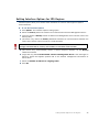
Setting Interface Options for Layer 2 Firewall Engines
Interface options allow you to select which interfaces are used for which types of system
communications.
To set the Interface Options
1. Click Options. The Interface Options dialog opens.
2. Select the Primary Control IP address for communications with the Management Server.
3. (Optional) Select a Backup Control IP address for Management Server contact (used if the
Primary fails).
4. (Layer 2 Firewall Cluster only) Select the Primary Heartbeat Interface for communications
between the nodes of the cluster. This must not be a VLAN Interface.
Caution – Heartbeat traffic is time-critical. A dedicated network (without other traffic) is
strongly recommended for security and reliability of heartbeat communication.
5. (Layer 2 Firewall Cluster only, recommended) Select a second Physical Interface as the
Backup Heartbeat interface.
6. (Single Layer 2 Firewall only) Select Node-initiated contact to Management Server if the
Layer 2 Firewall engine is behind a device that applies dynamic NAT to the inbound
management connections or blocks them.
7. (Optional) Select the Default IP Address for Outgoing Traffic.
8. Click OK.
Setting Interface Options for Layer 2 Firewall Engines
47
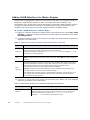
Defining Traffic Inspection Interfaces for Layer 2
Firewall Engines
Layer 2 Firewalls pick up passing network traffic for inspection in real time. The traffic can either
be captured for inspection through the engine’s Capture Interfaces, or it can be inspected as it
flows through the engine’s Inline Interfaces. You can define both Capture Interfaces and Inline
Interfaces for the same Layer 2 Firewall.
A Layer 2 Firewall can actively filter only traffic that attempts to pass through its Inline
Interfaces. However, it can reset traffic picked up through Capture Interfaces if you set up
specific Reset Interfaces. The Reset Interfaces can send TCP resets and ICMP “destination
unreachable” messages when the communications trigger a response. You can use a system
communications interface for sending resets if the resets are routed correctly through that
interface and there are no VLANs on the interface.
When traffic is inspected, it may be important to know the interface through which it arrives to
the Layer 2 Firewall engine. Logical Interface elements are used for this purpose. They allow you
to group together interfaces that belong to the same network segment and to identify the type of
the traffic inspection interface (Capture Interface or Inline Interface).
What’s Next?
If you want to create both Capture and Inline Interfaces on the same Layer 2 Firewall, or
if you want to create Logical Interfaces to distinguish interfaces from each other,
proceed to Defining Logical Interfaces.
If you do not want to use an existing system communication interface as the Reset
Interface, define the new Reset Interfaces as instructed in Defining Reset Interfaces
(page 49).
To define Capture Interfaces, proceed to Defining Capture Interfaces (page 50).
To define Inline Interfaces, proceed to Defining Inline Interfaces (page 51).
Defining Logical Interfaces
A Logical Interface is used in the Layer 2 Firewalls Policies and the traffic inspection process to
represent a network segment. The SMC contains one default Logical Interface. A Logical
Interface can represent any number or combination of interfaces and VLAN Interfaces. The rules
in the ready-made Layer 2 Firewall Template match all Logical Interfaces.
To define a Logical Interface
1. Select Configuration→Configuration→Security Engine. The Security Engine Configuration
view opens.
2. Expand the Other Elements branch.
3. Right-click Logical Interfaces and select New Logical Interface. The Logical Interface
Properties dialog opens.
4. Enter a unique Name.
5. (Optional) If you use VLAN tagging on Inline Interfaces, select View interface as one LAN if
you do not want the Layer 2 Firewall engine to see a single connection as multiple
connections when a switch passes traffic between different VLANs.
48
Chapter 6
Defining Layer 2 Firewalls
6. Click OK.
Repeat these steps to define any additional Logical Interfaces.
What’s Next?
If you want to use Reset Interfaces together with Capture Interfaces, define the Reset
Interfaces first. Proceed to Defining Reset Interfaces.
To define Capture Interfaces, proceed to Defining Capture Interfaces (page 50).
To define Inline Interfaces, proceed to Defining Inline Interfaces (page 51).
Defining Reset Interfaces
Reset Interfaces can deliver TCP resets and ICMP “destination unreachable” messages to
interrupt communications picked up from Capture Interfaces when the communications trigger a
response.
VLANs are supported for sending resets, but the correct VLAN is selected automatically. An
interface you want to use as the Reset Interface must not have any manually added VLAN
configuration.
The Reset Interface must be in the same broadcast domain as the Capture Interface that uses
the Reset Interface. The resets are sent using the IP addresses and MAC addresses of the
communicating hosts.
Note – An interface that is used only as a Reset Interface must not have an IP address.
To define a Reset Interface
1. Right-click and select New Physical Interface. The Physical Interface Properties dialog
opens.
2. Select the Interface ID.
3. Select Normal Interface as the Type.
4. Click OK.
This interface can now be used as a Reset Interface. When you set up the physical network,
make sure that the Reset Interface connects to the same network as the Capture Interface(s).
What’s Next?
Defining Capture Interfaces (page 50)
Defining Traffic Inspection Interfaces for Layer 2 Firewall Engines
49
Defining Capture Interfaces
Capture Interfaces listen to traffic that is not routed through the Layer 2 Firewall. You can have
as many Capture Interfaces as there are available physical ports on the Layer 2 Firewall (there
are no license restrictions regarding this interface type).
External equipment must be set up to mirror traffic to the Capture Interface. You can connect a
Capture Interface to a switch SPAN port. For more information, see Capture Interfaces
(page 19).
To define a Capture Interface
1. Right-click and select New Physical Interface. The Physical Interface Properties dialog
opens.
2. Select the Interface ID.
3. Select Capture Interface as the Type.
4. (Optional) Select a TCP Reset Interface for traffic picked up through this Capture Interface.
5. If your configuration requires you to change the Logical Interface from Default_Eth, select
the Logical Interface in one of the following ways:
• Select an existing Logical Interface from the list.
• Select Other and browse to another Logical Interface.
• Select New to create a new Logical Interface.
6. Leave Inspect Unspecified VLANs selected if you want the Layer 2 Firewall engine to
inspect traffic also from VLANs that are not included in the engine’s interface configuration.
7. Click OK.
Repeat these steps to define any additional Capture Interfaces.
What’s Next?
To define Inline Interfaces, proceed to Defining Inline Interfaces (page 51).
Otherwise, proceed to Finishing the Engine Configuration (page 51).
50
Chapter 6
Defining Layer 2 Firewalls
Defining Inline Interfaces
The number of Inline Interfaces you can have is limited by the license in use. One Inline
Interface always comprises two Physical Interfaces, as the traffic is forwarded from one
interface to the other. The allowed traffic passes through as if it was going through a network
cable. The traffic you want to stop is dropped by the Layer 2 Firewall.
Inline Interfaces are associated with a Logical Interface, which is used in the Layer 2 Firewall
policies and the traffic inspection process to represent one or more Layer 2 Firewall interfaces.
To define an Inline Interface
1. Right-click and select New Physical Interface. The Physical Interface Properties dialog
opens.
2. Select the Interface ID.
3. Select Inline Interface as the Type.
4. (Optional) Change the automatically selected Second Interface ID.
5. Leave Inspect Unspecified VLANs selected if you want the Layer 2 Firewall engine to
inspect traffic also from VLANs that are not included in the engine’s interface configuration.
6. If your configuration requires you to change the Logical Interface from Default_Eth, select
the Logical Interface in one of the following ways:
• Select an existing Logical Interface from the list.
• Select Other and browse to another Logical Interface.
• Select New to create a new Logical Interface.
7. Click OK.
Repeat these steps to define any additional Inline Interfaces.
What’s Next?
Proceed to Finishing the Engine Configuration.
Finishing the Engine Configuration
To finish the engine configuration
1. Write down the networks to which each Interface ID is connected
2. Click OK close the engine properties. You are prompted to open the Routing view.
3. Click No.
What’s Next?
You are now ready to transfer the configuration to the physical Layer 2 Firewall engines.
Proceed to Saving the Initial Configuration (page 83).
Finishing the Engine Configuration
51
52
Chapter 6
Defining Layer 2 Firewalls
C H A P TE R 7
CONFIGURING MASTER ENGINES
AND VIRTUAL IPS E NGINES
This chapter contains the steps needed to complete the Master Engine and Virtual IPS engine
configuration that prepares the SMC for a Master Engine and Virtual IPS engine installation.
Very little configuration is done directly on the Master Engine. No installation or configuration
is done on the Virtual IPS engines. Most of the configuration is done using the Management
Client, so the engines cannot be successfully installed before defining them in the
Management Client as outlined in this chapter.
The following sections are included:
Configuration Overview (page 54)
Adding a Master Engine Element (page 55)
Adding Nodes to a Master Engine (page 56)
Adding a Virtual Resource Element (page 56)
Adding Physical Interfaces for Master Engines (page 57)
Adding VLAN Interfaces for Master Engines (page 60)
Adding IPv4 Addresses for Master Engines (page 62)
Setting Global Interface Options for Master Engines (page 63)
Adding a Virtual IPS Engine Element (page 64)
Configuring Physical Interfaces for Virtual IPS Engines (page 65)
Adding VLAN Interfaces for Virtual IPS Engines (page 65)
Binding Engine Licenses to Correct Elements (page 66)
53
Configuration Overview
Virtual IPS engines are logically-separate Virtual Security Engines that run as virtual engine
instances on a physical engine device. A Master Engine is a physical engine device that provides
resources for Virtual IPS engines. One physical Master Engine can support multiple Virtual IPS
engines.
Each Master Engine can support one Virtual Security Engine role (Firewall/VPN, IPS, or Layer 2
Firewall). To use more than one Virtual Security Engine role, you must create a separate Master
Engine for each Virtual Security Engine role. Each Master Engine must be on a separate physical
Master Engine device.
The tasks you must complete are as follows:
1. Add a Master Engine element. See Adding a Master Engine Element (page 55).
2. Add a Virtual Resource element. See Adding a Virtual Resource Element (page 56).
3. Define Physical Interfaces and optionally VLAN Interfaces for the Master Engine, and
assign Virtual Resources to the interfaces that are used for hosted Virtual IPS engine
communications. See Adding Physical Interfaces for Master Engines (page 57) and Adding
VLAN Interfaces for Master Engines (page 60).
4. Add a Virtual IPS engine element. See Adding a Virtual IPS Engine Element (page 64).
5. Configure Physical Interfaces and optionally VLAN Interfaces for the Virtual IPS engine.
See Configuring Physical Interfaces for Virtual IPS Engines (page 65) and Adding VLAN
Interfaces for Virtual IPS Engines (page 65).
6. Bind Management Server POL-bound licenses to specific nodes in the Master Engine. See
Binding Engine Licenses to Correct Elements (page 66).
54
Chapter 7
Configuring Master Engines and Virtual IPS Engines
Adding a Master Engine Element
To introduce a new Master Engine to the SMC, you must define a Master Engine element that
stores the configuration information related to the Master Engine and Virtual IPS engines.
This section covers the basic configuration of a Master Engine element. For information on all
the options, see the McAfee SMC Administrator’s Guide or the Management Client Online Help.
To create a Master Engine element
1. Select Configuration→Configuration→Security Engine. The Security Engine Configuration
view opens.
2. Right-click Security Engines and select New→Other→Master Engine.
3. Select IPS as the role for the Virtual Security Engines that this Master Engine will host and
click OK. The Master Engine Properties dialog opens.
4. Give the element a unique Name.
5. Select the Log Server to which the Master Engine sends its log data.
6. (Optional) Define one or more DNS IP Addresses. These are the IP addresses of the DNS
server(s) that the Master Engine uses to resolve domain names. There are two ways to
define IP addresses.
• To enter a single IP address manually, click Add and select IP Address. Enter the IP
address in the dialog that opens.
• To define an IP address using a network element, click Add and select Network Element.
Select an existing element, or go to Tools→New and define a new element.
7. Select the Location for this Master Engine if there is a NAT device between this Master
Engine and other SMC components. See Defining Locations (page 29) for more
information.
8. (Optional) If you do not need to use clustering on the Master Engine, select one of the
nodes and click Remove Node. You are prompted to confirm that you want to delete the
selected node. Click Yes.
What’s Next?
If you want to add more nodes to the Master Engine, continue by Adding Nodes to a
Master Engine (page 56).
Otherwise, continue by Adding a Virtual Resource Element (page 56).
Adding a Master Engine Element
55
Adding Nodes to a Master Engine
The Master Engine properties have placeholders for two nodes when the element is created. A
Master Engine can have up to 16 nodes. Add all the nodes you plan to install before you begin
configuring the interfaces.
To add a node to a Master Engine
1. Click Add Node. The Engine Node Properties dialog opens.
2. (Optional) Modify the Name.
3. Click OK. The node is added to the Master Engine.
What’s Next?
Repeat these steps for each node that you want to add, then continue by Adding a
Virtual Resource Element.
Adding a Virtual Resource Element
Virtual Resources associate Virtual Security Engines with interfaces on the Master Engine.
To create a Virtual Resource element
1. Switch to the Interfaces tab of the Master Engine Properties and click Virtual Resources.
The Virtual Resources dialog opens.
2. Click Add. The Virtual Resource Properties dialog opens.
3. Enter a unique Name for the Virtual Resource.
4. Select the Domain to which the Virtual Resource belongs.
5. (Optional) Enter the Concurrent Connection Limit to set a limit for connections from a
single source and/or destination IP address. When the set number of connections is
reached, the next connection attempts are blocked by the engine until a previously open
connection is closed.
6. (Optional) Select Show Master Interface IDs in Virtual Engine if you want the Physical
Interface IDs of the Master Engine to be shown in the Interface properties of the Virtual IPS
engine.
7. Click OK. The Virtual Resource Properties dialog closes.
8. Click OK. The Virtual Resources dialog closes.
What’s Next?
Repeat these steps for all Virtual Resources that you want to add, then continue by
Adding Physical Interfaces for Master Engines (page 57).
56
Chapter 7
Configuring Master Engines and Virtual IPS Engines
Adding Physical Interfaces for Master Engines
Master Engines can have two types of Physical Interfaces: interfaces for the Master Engine’s
own communications, and interfaces that are used by the Virtual IPS engines hosted on the
Master Engine. Physical Interfaces that are used for the Master Engine’s own communications
must be defined as Normal Interfaces. Physical Interfaces that are used for hosted Virtual IPS
communications must be defined as Capture or Inline Interfaces.
You must define at least one Physical Interface for the Master Engine’s own communications. It
is recommended to define at least two Physical Interfaces for the Master Engine:
• An interface used for communications between the Management Server and the Firewall/VPN
engine.
• An interface for the heartbeat communications between the cluster nodes. The heartbeat
traffic is critical to the functioning of the cluster, so it is highly recommended to have a
dedicated heartbeat interface.
To add a Physical Interface to a Master Engine
1. Switch to the Interfaces tab of the Master Engine Properties.
2. Right-click the empty space and select New Physical Interface. The Physical Interface
Properties dialog opens.
3. (Interface for Master Engine communications only) Define the Physical Interface properties
as explained in the table below.
Table 7.1 Physical Interface Properties for Master Engine Communications - General Tab
Options
Explanation
Interface ID
The Interface ID automatically maps to a Physical Interface of the same number
during the initial configuration of the engine, but the mapping can be changed as
necessary through the engine’s command line interface.
Type
Select Normal Interface as the Interface Type for Master Engine communications.
MTU
(Optional)
The MTU (maximum transmission unit) size on the connected link. Either enter a
value between 400-65535 or select a common MTU value from the list.
The default value (also the maximum standard MTU in Ethernet) is 1500. Do not
set a value larger than the standard MTU unless you know that all the devices
along the communications path support it.
Adding Physical Interfaces for Master Engines
57
4. (Interface for hosted Virtual IPS engine communications only) Define the Physical Interface
properties as explained in the table below.
Table 7.2 Physical Interface Properties for Hosted Virtual IPS Engine Communications
Options
58
Explanation
Interface ID
The Interface ID automatically maps to a Physical Interface of the
same number during the initial configuration of the engine, but the
mapping can be changed as necessary through the engine's command
line interface. Changes to the Master Engine interface mapping do not
affect the Interface IDs that are defined for Virtual IPS engines in
Virtual Resource elements.
Type
Select Capture Interface or Inline Interface as the Interface Type for
hosted Virtual IPS engine communications.
Second Interface ID
(Inline Interface only)
Select a Second Interface ID for the Inline Interface. The Interface ID is
mapped to a Physical Interface during the initial configuration of the
engine.
Failure Mode
(Inline Interface only)
Select how traffic to the Inline Interface is handled if the Virtual IPS
engine goes offline.
There are two options:
Bypass: traffic is allowed through the Inline Interface without
inspection.
Normal: traffic is not allowed through the Inline Interface.
Note! If there are VLAN Interfaces under the Inline Interface, you must
select Bypass.
Caution! Using Bypass mode requires the Master Engine appliance to
have a fail-open network interface card. If the ports that represent the
pair of Inline Interface on the appliance cannot fail open, the policy
installation fails on the Virtual IPS engine. Bypass mode is not
compatible with VLAN re-tagging. In network environments where VLAN
re-tagging is used, Normal mode is automatically enforced.
Bypass Unspecified VLANs
(Inline Interface only)
When this option is selected, traffic from VLANs that are not allocated
to any Virtual IPS engine is bypassed without inspection. Deselect this
option to make the Master Engine block traffic from VLANs that are not
allocated to any Virtual IPS engine. We recommend that you keep this
option selected if you do not have a specific reason to deselect it.
Virtual Resource
The Virtual Resource associated with the interface. Select the same
Virtual Resource in the properties of the Virtual IPS engine element to
add the Virtual IPS engine to the Master Engine.
Only one Virtual Resource can be selected for each Physical Interface.
If you want to add multiple Virtual Resources, add VLAN Interfaces to
the Physical Interface and select the Virtual Resource in the VLAN
Interface properties as explained in Adding VLAN Interfaces for Master
Engines (page 60).
Allow VLAN Definition in
Virtual Engine
(Optional)
Select this option to allow VLAN Interfaces to be added to the
automatically created Physical Interfaces in the Virtual IPS engine that
is associated with this interface.
Chapter 7
Configuring Master Engines and Virtual IPS Engines
Table 7.2 Physical Interface Properties for Hosted Virtual IPS Engine Communications (Continued)
Options
Explanation
Virtual Engine Interface ID
Select the Interface ID of the Physical Interface in the Virtual IPS
engine that is associated with this interface.
Second Interface ID
(Inline Interface only)
Select the second Interface ID of the Inline Interface in the Virtual IPS
engine that is associated with this interface.
Throughput (kbps)
(Optional, Inline Interface
only)
Enter the maximum throughput for Virtual IPS engines that use this
interface as kilobits per second (for example, 2048). The same
throughput is automatically applied to any VLANs created under this
Physical Interface. See Adding VLAN Interfaces for Master Engines
(page 60).
MTU
(Optional)
The MTU (maximum transmission unit) size for Virtual IPS engines that
use this interface. Either enter a value between 400-65535 or select a
common MTU value from the list.
The default value (also the maximum standard MTU in Ethernet) is
1500. Do not set a value larger than the standard MTU unless you
know that all the devices along the communications path support it.
Reset Interface
(Optional, Capture Interface
only)
Select a TCP Reset Interface for traffic picked up through this Capture
Interface. This is the interface through which TCP connection resets
are sent when Reset responses are used in your IPS policy.
5. Click OK. The Physical Interface is added to the interface list.
6. Repeat from Step 2 to add any other Physical Interfaces.
What’s Next?
If you want to use VLANs on a Physical Interface, add the VLANs before adding IP
addresses. Proceed to Adding VLAN Interfaces for Master Engines (page 60).
Otherwise, add IP addresses directly to the Physical Interfaces used for Master Engine
communications as instructed in Adding IPv4 Addresses for Master Engines (page 62).
Adding Physical Interfaces for Master Engines
59
Adding VLAN Interfaces for Master Engines
VLANs divide a single physical network link into several virtual links. The maximum number of
VLANs for a single Physical Interface is 4094. The VLANs must also be defined in the
configuration of the switch/router to which the interface is connected. Master Engines can have
two types of VLAN Interfaces: interfaces for the Master Engine’s own communications, and
interfaces that are used by the Virtual IPS engines hosted on the Master Engine.
To add a VLAN Interface to a Master Engine
1. Right-click a Physical Interface for Master Engine communications and select New→VLAN
Interface, or a Physical Interface for hosted Virtual IPS engine communications and select
New VLAN Interface.
2. (Interface for Master Engine communications only) Define the VLAN Interface properties as
explained in the table below.
Table 7.3 VLAN Interface Properties for Master Engine Communications - General Tab
Option
Explanation
VLAN ID
Enter the VLAN ID (1-4094). The VLAN IDs you add must be the same as the VLAN IDs
that are used in the switch at the other end of the VLAN trunk.
Each VLAN Interface is identified as Interface-ID.VLAN-ID, for example 2.100 for
Interface ID 2 and VLAN ID 100.
Zone
Select the network zone to which the Physical Interface belongs from the list or select
Other to select another Zone. If the Zone is not listed, select New to create a new Zone
element.
MTU
(Optional)
The MTU (maximum transmission unit) size on the connected link. Either enter a value
between 400-65535 or select a common MTU value from the list. If MTU is defined for
the Physical Interface to which the VLAN Interface belongs, the MTU value is
automatically inherited from the Physical Interface properties.
Caution! The MTU for each VLAN Interface must not be higher than the MTU for the
Physical Interface to which the VLAN Interface belongs.
The default value (also the maximum standard MTU in Ethernet) is 1500. Do not set a
value larger than the standard MTU unless you know that all the devices along the
communications path support it.
3. (Interface for hosted Virtual IPS engine communications only) Define the VLAN Interface
properties as explained in the table below.
Table 7.4 VLAN Interface Properties for Hosted Virtual IPS Engine Communications
Option
VLAN ID
60
Chapter 7
Explanation
Enter the VLAN ID (1-4094). The VLAN IDs you add must be the same as the
VLAN IDs that are used in the switch at the other end of the VLAN trunk.
Each VLAN Interface is identified as Interface-ID.VLAN-ID, for
example 2.100 for Interface ID 2 and VLAN ID 100.
Configuring Master Engines and Virtual IPS Engines
Table 7.4 VLAN Interface Properties for Hosted Virtual IPS Engine Communications (Continued)
Option
Explanation
Second VLAN ID
(Optional, only if Physical
Interface Type is Inline
Interface)
Enter a Second VLAN ID for the Inline Interface if you want to remap the
Inline Interface. By default, this value is inherited from the first VLAN ID. We
recommend that you keep the default value if you do not have a specific
reason to change it.
Virtual Resource
The Virtual Resource associated with the interface. Select the same Virtual
Resource in the properties of the Virtual IPS engine element to add the
Virtual IPS engine to the Master Engine. Only one Virtual Resource can be
selected for each VLAN Interface.
Virtual Engine Interface
ID
Select the Interface ID of the Physical Interface in the Virtual IPS engine that
is associated with this interface.
Second Interface ID
(Inline Interface only)
Select the second Interface ID of the Inline Interface in the Virtual IPS
engine that is associated with this interface.
Throughput (kbps)
(Optional, only if Physical
Interface Type is Inline
Interface)
The maximum throughput for the IPS engines that use this VLAN Interface.
Enter the throughput as kilobits per second (for example, 2048). If
throughput is defined for the Physical Interface to which the VLAN Interface
belongs, the throughput value is automatically inherited from the Physical
Interface properties.
Caution! The throughput for each VLAN Interface must not be higher than
the throughput for the Physical Interface to which the VLAN Interface
belongs.
The throughput is for uplink speed (outgoing traffic) and typically must
correspond to the speed of an Internet link (such as an ADSL line), or the
combined speeds of several such links when they are connected to a single
Physical Interface.
Caution! Make sure you set the interface speed correctly. When the
bandwidth is set, the Master Engine always scales the total amount of
traffic on this interface to the bandwidth you defined. This happens even if
there are no bandwidth limits or guarantees defined for any traffic.
MTU
(Optional)
The MTU (maximum transmission unit) size for Virtual IPS engines that use
this interface. Either enter a value between 400-65535 or select a common
MTU value from the list.
Caution! The MTU for each VLAN Interface must not be higher than the MTU
for the Physical Interface to which the VLAN Interface belongs.
The default value (also the maximum standard MTU in Ethernet) is 1500.
Do not set a value larger than the standard MTU unless you know that all
the devices along the communications path support it.
Reset Interface
(Optional, only if Physical
Interface Type is Capture
Interface)
Select a TCP Reset Interface for traffic picked up through this Capture
Interface. This is the interface through which TCP connection resets are
sent when Reset responses are used in your IPS policy.
4. Click OK. The specified VLAN ID is added to the Physical Interface.
Adding VLAN Interfaces for Master Engines
61
5. Repeat from Step 2 to add further VLANs on the same or other Physical Interfaces.
What’s Next?
Add IP addresses to the VLAN Interfaces used for Master Engine communications as
instructed in Adding IPv4 Addresses for Master Engines.
Adding IPv4 Addresses for Master Engines
You can add several IPv4 addresses to each Physical Interface that has been defined as a
Normal Interface. You must add at least one IPv4 address to at least one Normal Interface.
To add IPv4 addresses for a Master Engine
1. Make sure you are on the Interfaces tab.
2. Right-click a Physical Interface and select New→IPv4 Address or a VLAN Interface and
select New IPv4 Address. The IP Address Properties dialog opens.
Note – If the Normal Interface has VLAN Interfaces, you must add the IPv4 addresses to
the VLAN Interfaces.
3. Enter the IPv4 Address for each node.
4. If necessary, double-click the Contact Address field and define the contact address(es).
• Enter the Default contact address. The default contact address is used by default
whenever a component that belongs to another Location connects to this interface.
• If components from some Locations cannot use the Default contact address, click Add to
define Location-specific contact addresses.
5. Check the automatically filled-in Netmask and adjust it as necessary.
6. Click OK. Repeat from Step 2 to add further IPv4 addresses to the same or other
interfaces.
What’s Next?
If you want to change the roles the different interfaces have in the configuration,
proceed to Setting Global Interface Options for Master Engines (page 63).
Otherwise, proceed to Adding a Virtual IPS Engine Element (page 64).
62
Chapter 7
Configuring Master Engines and Virtual IPS Engines
Setting Global Interface Options for Master Engines
The Interface Options dialog contains the settings for selecting which IP addresses are used in
particular roles in system communications (for example, in communications between the Master
Engine and the Management Server). Only IPv4 addresses are used in system communications.
To set global interface options for a Master Engine
1. Click Options. The Interface Options dialog opens.
2. Select the interface options as explained in the table below.
Table 7.5 Master Engine Interface Options
Option
Explanation
Select the Primary Control IP address for Management Server contact.
Control Interface
(Optional) Select a Backup Control IP address that is used if the Primary
Control IP address is not available.
Select the Primary Heartbeat Interface for communications between the
nodes. We recommend that you use a Physical Interface, not a VLAN
Interface. We strongly recommend that you do not direct any other traffic
through this interface. A dedicated network helps ensure reliable and
secure operation.
Caution! Primary and Backup Heartbeat networks exchange confidential
information.
Heartbeat Interface
Default IP Address for
Outgoing Traffic
Select a Backup Heartbeat Interface that is used if the Primary Heartbeat
Interface is unavailable. It is not mandatory to configure a Backup
Heartbeat Interface, but we strongly recommend it. If heartbeat traffic is not
delivered, the cluster cannot operate and traffic will be disturbed. We
strongly recommend that you use a dedicated interface for the backup
heartbeat as well.
Caution! Primary and Backup Heartbeat networks exchange confidential
information.
This option defines the IP address that the nodes use if they have to initiate
connections (system communications, ping, etc.) through an interface that
has no IP Address. You must select an interface that has an IP address
defined for all nodes.
3. Click OK.
The interfaces you have defined are shown as a tree-table on the Interfaces tab. Global
interface options have codes in the tree-table:
• “C” and “c” are the interfaces that have the Primary and Secondary Control IP addresses
• “H” and “h” are the Primary and Secondary Heartbeat Interfaces
• “O” is the default IP address for outgoing connections
Double-click to edit the interface. Make sure you do this at the correct level for the properties
you want to edit.
Setting Global Interface Options for Master Engines
63
4. Click OK to close the Master Engine Properties. A Confirmation dialog opens. Click No.
What’s Next?
Adding a Virtual IPS Engine Element (page 64)
Adding a Virtual IPS Engine Element
This section covers the basic configuration of a Virtual IPS engine element. For information on
all the options, see the McAfee SMC Administrator’s Guide or the Management Client Online
Help.
To create a Virtual IPS engine element
1. Select Configuration→Configuration→Security Engine. The Security Engine Configuration
view opens.
2. Right-click Security Engines and select New→IPS→Virtual IPS. The Virtual IPS Properties
dialog opens.
3. Give the element a unique Name.
4. Click Select and select a Virtual Resource on the Master Engine to which you want to add
the Virtual IPS engine.
What’s Next?
If you want to modify the automatically-created Physical Interfaces, proceed to
Configuring Physical Interfaces for Virtual IPS Engines (page 65).
If you want to divide any of the Physical Interfaces into VLANs, continue by Adding VLAN
Interfaces for Virtual IPS Engines (page 65).
If the Security Engine licenses for the Master Engine were generated based on the POL
code of the Management Server (instead of the Master Engine’s POS code), proceed to
Binding Engine Licenses to Correct Elements (page 66).
Otherwise, proceed to Saving the Initial Configuration (page 83).
64
Chapter 7
Configuring Master Engines and Virtual IPS Engines
Configuring Physical Interfaces for Virtual IPS Engines
Physical Interfaces for Virtual IPS engines represent interfaces allocated to the Virtual IPS
engine in the Master Engine. When you select the Virtual Resource for the Virtual IPS engine,
Physical Interfaces are automatically created based on the interface configuration in the Master
Engine properties. The number of Physical Interfaces depends on the number of interfaces
allocated to the Virtual IPS engine in the Master Engine. It is not recommended to create new
Physical Interfaces in the Virtual IPS engine properties, as they may not be valid.
You can optionally modify the automatically-created Physical Interfaces in the Virtual IPS engine
properties. For detailed instructions, see the McAfee SMC Administrator’s Guide or the
Management Client Online Help.
What’s Next?
If you want to divide any of the Physical Interfaces into VLANs, continue by Adding VLAN
Interfaces for Virtual IPS Engines.
If the Security Engine licenses for the Master Engine were generated based on the POL
code of the Management Server (instead of the Master Engine’s POS code), proceed to
Binding Engine Licenses to Correct Elements (page 66).
Otherwise, you are ready to transfer the configuration to the physical Master Engine
nodes. Proceed to Saving the Initial Configuration (page 83).
Adding VLAN Interfaces for Virtual IPS Engines
VLAN Interfaces can only be added for Virtual IPS engines if the creation of VLAN Interfaces for
Virtual IPS engines is enabled in the Master Engine Properties. VLANs divide a single physical
network link into several virtual links. The maximum number of VLANs for a single Physical
Interface is 4094. The VLANs must also be defined in the configuration of the switch/router to
which the interface is connected.
Note – You cannot add VLAN Interfaces on top of other VLAN Interfaces. Depending on the
configuration of the Master Engine that hosts the Virtual IPS engine, you may not be able
to create valid VLAN Interfaces for the Virtual IPS engine. See Adding a Master Engine
Element (page 55).
To add a VLAN Interface for a Virtual IPS engine
1. Switch to the Interfaces tab.
2. Right-click a Physical Interface and select New VLAN Interface. The VLAN Interface
Properties dialog opens.
3. Enter the VLAN ID (1-4094). The VLAN IDs you add must be the same as the VLAN IDs that
are used in the switch at the other end of the VLAN trunk.
• Each VLAN Interface is identified as Interface-ID.VLAN-ID, for example 2.100 for
Interface ID 2 and VLAN ID 100.
Configuring Physical Interfaces for Virtual IPS Engines
65
4. If your configuration requires you to change the Logical Interface from Default_Eth, select
the Logical Interface in one of the following ways:
• Select an existing Logical Interface from the list.
• Select Other and browse to another Logical Interface.
• Select New to create a new Logical Interface.
5. (Optional, only if Physical Interface Type is Inline Interface) Enter a VLAN ID for the Second
Interface in the Inline Interface if you want to remap the Inline Interface.
• By default, this value is inherited from the first VLAN ID. We recommend that you keep the
default value if you do not have a specific reason to change it.
6. Click OK. The specified VLAN ID is added to the Physical Interface.
7. (Optional) Repeat the steps above to add further VLAN Interfaces.
What’s Next?
If the Security Engine licenses for the Master Engine were generated based on the POL
code of the Management Server (instead of the Master Engine’s POS code), proceed to
Binding Engine Licenses to Correct Elements.
Otherwise, you are ready to transfer the configuration to the physical Master Engine
nodes. Proceed to Saving the Initial Configuration (page 83).
Binding Engine Licenses to Correct Elements
Licenses are created based on the Management Server’s proof-of-license (POL) code or based
on the appliance's proof-of-serial (POS) code. You must manually bind Management Server POLbound licenses to a specific Master Engine element. POS-bound appliance licenses are
automatically bound to the correct Master Engine element when the engine is fully installed.
Virtual IPS engines do not require a separate license.
To bind a Management Server POL-bound license to a Master Engine Node
1. Select Configuration→Configuration→Administration. The Administration Configuration
view opens.
2. Browse to Licenses→Security Engines. All installed licenses appear in the right panel.
3. Right-click a Management Server POL-bound license and select Bind. The Select License
Binding dialog opens.
4. Select the node and click Select. The license is now bound to the selected node.
• If you made a mistake, right-click the license and select Unbind.
• Repeat the steps to bind the Management Server POL-bound licenses to all the Master
Engine nodes.
Caution – When you install or refresh the policy on the engine, the license is permanently
bound to that engine. Permanently-bound licenses cannot be re-bound to another engine
without re-licensing or deleting the engine element the license is bound to. Until you do
that, the unbound license is shown as Retained.
What’s Next?
You are now ready to transfer the configuration to the physical Master Engine nodes.
Proceed to Saving the Initial Configuration (page 83).
66
Chapter 7
Configuring Master Engines and Virtual IPS Engines
C H A P TE R 8
CONFIGURING MASTER ENGINES
AND VIRTUAL LAYER 2 FIREWALLS
This chapter contains the steps needed to complete the Master Engine and Virtual Layer 2
Firewall configuration that prepares the Security Management Center for a Master Engine and
Virtual Layer 2 Firewall installation.
Very little configuration is done directly on the Master Engine. No installation or configuration
is done on the Virtual Layer 2 Firewalls. Most of the configuration is done using the
Management Client, so the engines cannot be successfully installed before defining them in
the Management Client as outlined in this chapter.
The following sections are included:
Configuration Overview (page 68)
Adding a Master Engine Element (page 69)
Adding Nodes to a Master Engine (page 70)
Adding a Virtual Resource Element (page 70)
Adding Physical Interfaces for Master Engines (page 71)
Adding VLAN Interfaces for Master Engines (page 74)
Adding IPv4 Addresses for Master Engines (page 76)
Setting Global Interface Options for Master Engines (page 77)
Adding a Virtual Layer 2 Firewall Element (page 78)
Configuring Physical Interfaces for Virtual Layer 2 Firewalls (page 79)
Adding VLAN Interfaces for Virtual Layer 2 Firewalls (page 80)
Binding Engine Licenses to Correct Elements (page 81)
67
Configuration Overview
Virtual Layer 2 Firewalls are logically-separate Virtual Security Engines that run as virtual engine
instances on a physical engine device. A Master Engine is a physical engine device that provides
resources for Virtual Security Engines. One physical Master Engine can support multiple Virtual
Layer 2 Firewalls.
Each Master Engine can support one Virtual Security Engine role (Firewall/VPN, IPS, or Layer 2
Firewall). To use more than one Virtual Security Engine role, you must create a separate Master
Engine for each Virtual Security Engine role. Each Master Engine must be on a separate physical
Master Engine device.
The tasks you must complete are as follows:
1. Add a Master Engine element. See Adding a Master Engine Element (page 69).
2. Add a Virtual Resource element. See Adding a Virtual Resource Element (page 70).
3. Define Physical Interfaces and optionally VLAN Interfaces for the Master Engine, and
assign Virtual Resources to the interfaces. See Adding Physical Interfaces for Master
Engines (page 71) and Adding VLAN Interfaces for Master Engines (page 74).
4. Add a Virtual Layer 2 Firewall element. See Adding a Virtual Layer 2 Firewall Element
(page 78).
5. Configure Physical Interfaces and optionally VLAN Interfaces for the Virtual Layer 2
Firewall. See Configuring Physical Interfaces for Virtual Layer 2 Firewalls (page 79) and
Adding VLAN Interfaces for Virtual Layer 2 Firewalls (page 80).
6. Bind Management Server POL-bound licenses to specific nodes in the Master Engine. See
Binding Engine Licenses to Correct Elements (page 81).
68
Chapter 8
Configuring Master Engines and Virtual Layer 2 Firewalls
Adding a Master Engine Element
To introduce a new Master Engine to the SMC, you must define a Master Engine element that
stores the configuration information related to the Master Engine and Virtual Layer 2 Firewalls.
This section covers the basic configuration of a Master Engine element. For information on all
the options, see the McAfee SMC Administrator’s Guide or the Management Client Online Help.
To create a Master Engine element
1. Select Configuration→Configuration→Security Engine. The Security Engine Configuration
view opens.
2. Right-click Security Engines and select New→Other→Master Engine.
3. Select Layer 2 Firewall as the role for the Virtual Security Engines that this Master Engine
will host and click OK. The Master Engine Properties dialog opens.
4. Give the element a unique Name.
5. Select the Log Server to which the Master Engine sends its log data.
6. (Optional) Define one or more DNS IP Addresses. These are the IP addresses of the DNS
server(s) that the Master Engine uses to resolve domain names. There are two ways to
define IP addresses.
• To enter a single IP address manually, click Add and select IP Address. Enter the IP
address in the dialog that opens.
• To define an IP address using a network element, click Add and select Network Element.
Select an existing element, or go to Tools→New and define a new element.
7. Select the Location for this Master Engine if there is a NAT device between this Master
Engine and other SMC components. See Defining Locations (page 29) for more
information.
8. (Optional) If you do not need to use clustering on the Master Engine, select one of the
nodes and click Remove Node. You are prompted to confirm that you want to delete the
selected node. Click Yes.
What’s Next?
If you want to add more nodes to the Master Engine, continue by Adding Nodes to a
Master Engine (page 70).
Otherwise, continue by Adding a Virtual Resource Element (page 70).
Adding a Master Engine Element
69
Adding Nodes to a Master Engine
The Master Engine properties have placeholders for two nodes when the element is created. A
Master Engine can have up to 16 nodes. Add all the nodes you plan to install before you begin
configuring the interfaces.
To add a node to a Master Engine
1. Click Add Node. The Engine Node Properties dialog opens.
2. (Optional) Modify the Name.
3. Click OK. The node is added to the Master Engine.
What’s Next?
Repeat these steps for each node that you want to add, then continue by Adding a
Virtual Resource Element.
Adding a Virtual Resource Element
Virtual Resources associate Virtual Security Engines with interfaces on the Master Engine.
To create a Virtual Resource element
1. Switch to the Interfaces tab of the Master Engine Properties and click Virtual Resources.
The Virtual Resources dialog opens.
2. Click Add. The Virtual Resource Properties dialog opens.
3. Enter a unique Name for the Virtual Resource.
4. Select the Domain to which the Virtual Resource belongs.
5. (Optional) Enter the Concurrent Connection Limit to set a limit for connections from a
single source and/or destination IP address. When the set number of connections is
reached, the next connection attempts are blocked by the engine until a previously open
connection is closed.
6. (Optional) Select Show Master Interface IDs in Virtual Engine if you want the Physical
Interface IDs of the Master Engine to be shown in the Interface properties of the Virtual
Layer 2 Firewall.
7. Click OK. The Virtual Resource Properties dialog closes.
8. Click OK. The Virtual Resources dialog closes.
What’s Next?
Repeat these steps for all Virtual Resources that you want to add, then continue by
Adding Physical Interfaces for Master Engines (page 71).
70
Chapter 8
Configuring Master Engines and Virtual Layer 2 Firewalls
Adding Physical Interfaces for Master Engines
Master Engines can have two types of Physical Interfaces: interfaces for the Master Engine’s
own communications, and interfaces that are used by the Virtual Layer 2 Firewalls hosted on the
Master Engine. Physical Interfaces that are used for the Master Engine’s own communications
must be defined as Normal Interfaces. Physical Interfaces that are used for hosted Virtual Layer
2 Firewall communications must be defined as Inline or Capture Interfaces.
You must define at least one Physical Interface for the Master Engine’s own communications. It
is recommended to define at least two Physical Interfaces for the Master Engine:
• An interface used for communications between the Management Server and the Firewall/VPN
engine.
• An interface for the heartbeat communications between the cluster nodes. The heartbeat
traffic is critical to the functioning of the cluster, so it is highly recommended to have a
dedicated heartbeat interface.
To add a Physical Interface to a Master Engine
1. Switch to the Interfaces tab of the Master Engine Properties.
2. Right-click the empty space and select New Physical Interface. The Physical Interface
Properties dialog opens.
3. (Interface for Master Engine communications only) Define the Physical Interface properties
as explained in the table below.
Table 8.1 Physical Interface Properties for Master Engine Communications
Options
Explanation
Interface ID
The Interface ID automatically maps to a Physical Interface of the same number
during the initial configuration of the engine, but the mapping can be changed as
necessary through the engine’s command line interface.
Type
Select Normal Interface as the Interface Type for Master Engine Communications.
MTU
(Optional)
The MTU (maximum transmission unit) size on the connected link. Either enter a
value between 400-65535 or select a common MTU value from the list.
The default value (also the maximum standard MTU in Ethernet) is 1500. Do not
set a value larger than the standard MTU unless you know that all the devices along
the communications path support it.
Adding Physical Interfaces for Master Engines
71
4. (Interface for Hosted Virtual Layer 2 Firewall communications only) Define the Physical
Interface properties as explained in the table below.
Table 8.2 Physical Interface Properties for Hosted Virtual Layer 2 Firewall Communications
Options
72
Explanation
Interface ID
The Interface ID automatically maps to a Physical Interface of the same
number during the initial configuration of the engine, but the mapping
can be changed as necessary through the engine’s command line
interface.
Type
Select Inline Interface or Capture Interface as the Interface Type for
hosted Virtual Layer 2 Firewall communications.
Second Interface ID
(Inline Interface only)
Select a Second Interface ID for the Inline Interface. The Interface ID is
mapped to a Physical Interface during the initial configuration of the
engine.
Bypass Unspecified VLANs
(Inline Interface only)
When this option is not selected, the Master Engine blocks traffic from
VLANs that are not allocated to any Virtual Layer 2 Firewall. Select this
option to make the Master Engine bypass traffic from VLANs that are not
allocated to any Virtual Layer 2 Firewall without inspection. We
recommend that you keep this option deselected if you do not have a
specific reason to select it.
Virtual Resource
The Virtual Resource associated with the interface. Select the same
Virtual Resource in the properties of the Virtual Layer 2 Firewall element
to add the Virtual Layer 2 Firewall to the Master Engine.
Only one Virtual Resource can be selected for each Physical Interface. If
you want to add multiple Virtual Resources, add VLAN Interfaces to the
Physical Interface and select the Virtual Resource in the VLAN Interface
properties as explained in Adding VLAN Interfaces for Master Engines
(page 74).
Allow VLAN Definition in
Virtual Engine (Optional)
Select this option to allow VLAN Interfaces to be added to the
automatically created Physical Interfaces in the Virtual Layer 2 Firewall
that is associated with this interface.
Virtual Engine Interface ID
Select the Interface ID of the Physical Interface in the Virtual Layer 2
Firewall that is associated with this interface.
Second Interface ID
(Inline Interface only)
Select the second Interface ID of the Inline Interface in the Virtual Layer
2 Firewall that is associated with this interface.
Throughput (kbps)
(Optional, Inline Interface
only)
Enter the maximum throughput for Virtual Layer 2 Firewalls that use this
interface as kilobits per second (for example, 2048). The same
throughput is automatically applied to any VLANs created under this
Physical Interface. See Adding VLAN Interfaces for Master Engines
(page 74).
Chapter 8
Configuring Master Engines and Virtual Layer 2 Firewalls
Table 8.2 Physical Interface Properties for Hosted Virtual Layer 2 Firewall Communications (Continued)
Options
Explanation
MTU
(Optional)
The MTU (maximum transmission unit) size for Virtual Layer 2 Firewalls
that use this interface. Either enter a value between 400-65535 or select
a common MTU value from the list.
The default value (also the maximum standard MTU in Ethernet) is 1500.
Do not set a value larger than the standard MTU unless you know that all
the devices along the communications path support it.
Reset Interface
(Optional, Capture Interface
only)
Select a TCP Reset Interface for traffic picked up through this Capture
Interface. This is the interface through which TCP connection resets are
sent when Reset responses are used in your Layer 2 Firewall policy.
5. Click OK. The Physical Interface is added to the interface list.
6. Repeat from Step 2 to add any other Physical Interfaces.
What’s Next?
If you want to use VLANs on a Physical Interface, add the VLANs before adding IP
addresses. Proceed to Adding VLAN Interfaces for Master Engines (page 74).
Otherwise, add IP addresses directly to the Physical Interfaces used for Master Engine
communications as instructed in Adding IPv4 Addresses for Master Engines (page 76).
Adding Physical Interfaces for Master Engines
73
Adding VLAN Interfaces for Master Engines
VLANs divide a single physical network link into several virtual links. The maximum number of
VLANs for a single Physical Interface is 4094. The VLANs must also be defined in the
configuration of the switch/router to which the interface is connected. Master Engines can have
two types of VLAN Interfaces: interfaces for the Master Engine’s own communications, and
interfaces that are used by the Virtual Layer 2 Firewalls hosted on the Master Engine.
To add a VLAN Interface to a Master Engine
1. Right-click a Physical Interface for Master Engine communications and select New→VLAN
Interface, or a Physical Interface for hosted Virtual Layer 2 Firewall communications and
select New VLAN Interface. The VLAN Interface Properties dialog opens.
2. (Interface for Master Engine communications only) Define the VLAN Interface properties as
explained in the table below.
Table 8.3 VLAN Interface Properties for Master Engine Communications
Option
Explanation
VLAN ID
Enter the VLAN ID (1-4094). The VLAN IDs you add must be the same as the VLAN IDs
that are used in the switch at the other end of the VLAN trunk.
Each VLAN Interface is identified as Interface-ID.VLAN-ID, for example 2.100 for
Interface ID 2 and VLAN ID 100.
Zone
Select the network zone to which the Physical Interface belongs from the list or select
Other to select another Zone. If the Zone is not listed, select New to create a new Zone
element.
MTU
(Optional)
The MTU (maximum transmission unit) size on the connected link. Either enter a value
between 400-65535 or select a common MTU value from the list. If MTU is defined for
the Physical Interface to which the VLAN Interface belongs, the MTU value is
automatically inherited from the Physical Interface properties.
Caution! The MTU for each VLAN Interface must not be higher than the MTU for the
Physical Interface to which the VLAN Interface belongs.
The default value (also the maximum standard MTU in Ethernet) is 1500. Do not set a
value larger than the standard MTU unless you know that all the devices along the
communications path support it.
3. (Interface for hosted Virtual Layer 2 Firewall communications only) Define the VLAN Interface
properties as explained in the table below.
Table 8.4 VLAN Interface Properties for Hosted Virtual Layer 2 Firewall Communications
Option
VLAN ID
74
Chapter 8
Explanation
Enter the VLAN ID (1-4094). The VLAN IDs you add must be the same as the
VLAN IDs that are used in the switch at the other end of the VLAN trunk.
Each VLAN Interface is identified as Interface-ID.VLAN-ID, for
example 2.100 for Interface ID 2 and VLAN ID 100.
Configuring Master Engines and Virtual Layer 2 Firewalls
Table 8.4 VLAN Interface Properties for Hosted Virtual Layer 2 Firewall Communications (Continued)
Option
Explanation
Second VLAN ID
(Optional, only if Physical
Interface Type is Inline
Interface)
Enter a Second VLAN ID for the Inline Interface if you want to remap the
Inline Interface. By default, this value is inherited from the first VLAN ID. We
recommend that you keep the default value if you do not have a specific
reason to change it.
Virtual Resource
The Virtual Resource associated with the interface. Select the same Virtual
Resource in the properties of the Virtual Layer 2 Firewall element to add the
Virtual Layer 2 Firewall to the Master Engine. Only one Virtual Resource can
be selected for each VLAN Interface.
Virtual Engine Interface
ID
Select the Interface ID of the Physical Interface in the Virtual Layer 2
Firewall that is associated with this interface.
Second Interface ID
(Inline Interface only)
Select the second Interface ID of the Inline Interface in the Virtual Layer 2
Firewall that is associated with this interface.
Throughput (kbps)
(Optional, only if Physical
Interface Type is Inline
Interface)
The maximum throughput for the Virtual Layer 2 Firewalls that use this VLAN
Interface. Enter the throughput as kilobits per second (for example, 2048).
If throughput is defined for the Physical Interface to which the VLAN
Interface belongs, the throughput value is automatically inherited from the
Physical Interface properties.
Caution! The throughput for each VLAN Interface must not be higher than
the throughput for the Physical Interface to which the VLAN Interface
belongs.
The throughput is for uplink speed (outgoing traffic) and typically must
correspond to the speed of an Internet link (such as an ADSL line), or the
combined speeds of several such links when they are connected to a single
Physical Interface.
Caution! Make sure you set the interface speed correctly. When the
bandwidth is set, the Master Engine always scales the total amount of
traffic on this interface to the bandwidth you defined. This happens even if
there are no bandwidth limits or guarantees defined for any traffic.
MTU
(Optional)
The MTU (maximum transmission unit) size for Virtual Layer 2 Firewalls that
use this interface. Either enter a value between 400-65535 or select a
common MTU value from the list. If MTU is defined for the Physical Interface
to which the VLAN Interface belongs, the MTU value is automatically
inherited from the Physical Interface properties.
Caution! The MTU for each VLAN Interface must not be higher than the MTU
for the Physical Interface to which the VLAN Interface belongs.
The default value (also the maximum standard MTU in Ethernet) is 1500.
Do not set a value larger than the standard MTU unless you know that all
the devices along the communications path support it.
Reset Interface
(Optional, only if Physical
Interface Type is Capture
Interface)
Select a TCP Reset Interface for traffic picked up through this Capture
Interface. This is the interface through which TCP connection resets are
sent when Reset responses are used in your Layer 2 Firewall policy.
4. Click OK. The specified VLAN ID is added to the Physical Interface.
Adding VLAN Interfaces for Master Engines
75
5. Repeat from Step 2 to add further VLANs on the same or other Physical Interfaces.
What’s Next?
Add IP addresses to the VLAN Interfaces used for Master Engine communications as
instructed in Adding IPv4 Addresses for Master Engines.
Adding IPv4 Addresses for Master Engines
You can add several IPv4 addresses to each Physical Interface that has been defined as a
Normal Interface. You must add at least one IPv4 address to at least one Normal Interface.
To add IPv4 addresses for a Master Engine
1. Make sure you are on the Interfaces tab.
2. Right-click a Physical Interface and select New→IPv4 Address or a VLAN Interface and
select New IPv4 Address. The IP Address Properties dialog opens.
Note – If the Normal Interface has VLAN Interfaces, you must add the IPv4 addresses to
the VLAN Interfaces.
3. Enter the IPv4 Address for each node.
4. If necessary, double-click the Contact Address field and define the contact address(es).
• Enter the Default contact address. The default contact address is used by default
whenever a component that belongs to another Location connects to this interface.
• If components from some Locations cannot use the Default contact address, click Add to
define Location-specific contact addresses.
5. Check the automatically filled-in Netmask and adjust it as necessary.
6. Click OK. Repeat from Step 2 to add further IPv4 addresses to the same or other
interfaces.
What’s Next?
If you want to change the roles the different interfaces have in the configuration,
proceed to Setting Global Interface Options for Master Engines (page 77).
Otherwise, proceed to Adding a Virtual Layer 2 Firewall Element (page 78).
76
Chapter 8
Configuring Master Engines and Virtual Layer 2 Firewalls
Setting Global Interface Options for Master Engines
The Interface Options dialog contains the settings for selecting which IP addresses are used in
particular roles in system communications (for example, in communications between the Master
Engine and the Management Server). Only IPv4 addresses are used in system communications.
To set global interface options for a Master Engine
1. Click Options. The Interface Options dialog opens.
2. Select the interface options as explained in the table below.
Table 8.5 Master Engine Interface Options
Option
Explanation
Select the Primary control IP address for Management Server contact.
Control Interface
(Optional) Select a Backup control IP address that is used if the Primary control
IP address is not available.
Select the Primary Heartbeat Interface for communications between the nodes.
We recommend that you use a Physical Interface, not a VLAN Interface. We
strongly recommend that you do not direct any other traffic through this interface.
A dedicated network helps ensure reliable and secure operation.
Caution! Primary and Backup Heartbeat networks exchange confidential
information.
Heartbeat Interface
Default IP Address
for Outgoing Traffic
Select a Backup Heartbeat Interface that is used if the Primary Heartbeat
Interface is unavailable. It is not mandatory to configure a Backup Heartbeat
Interface, but we strongly recommend it. If heartbeat traffic is not delivered, the
cluster cannot operate and traffic will be disturbed. We strongly recommend that
you use a dedicated interface for the backup heartbeat as well.
Caution! Primary and Backup Heartbeat networks exchange confidential
information.
This option defines the IP address that the nodes use if they have to initiate
connections (system communications, ping, etc.) through an interface that has
no IP Address. You must select an interface that has an IP address defined for
all nodes.
3. Click OK.
The interfaces you have defined are shown as a tree-table on the Interfaces tab. Global
interface options have codes in the tree-table:
• “C” and “c” are the interfaces that have the Primary and Secondary Control IP addresses
• “H” and “h” are the Primary and Secondary Heartbeat Interfaces
• “O” is the default IP address for outgoing connections
Double-click to edit the interface. Make sure you do this at the correct level for the properties
you want to edit.
Setting Global Interface Options for Master Engines
77
4. Click OK to close the Master Engine Properties. A Confirmation dialog opens. Click No.
What’s Next?
Adding a Virtual Layer 2 Firewall Element
Adding a Virtual Layer 2 Firewall Element
This section covers the basic configuration of a Virtual Layer 2 Firewall. For information on all
the options, see the McAfee SMC Administrator’s Guide or the Management Client Online Help.
To create a Virtual Layer 2 Firewall element
1. Select Configuration→Configuration→Security Engine. The Security Engine Configuration
view opens.
2. Right-click Security Engines and select New→Layer 2 Firewall→Virtual Layer 2 Firewall.
The Virtual Layer 2 Firewall Properties dialog opens.
3. Give the element a unique Name.
4. Click Select and select a Virtual Resource on the Master Engine to which you want to add
the Virtual Layer 2 Firewall.
What’s Next?
If you want to modify the automatically-created Physical Interfaces, proceed to
Configuring Physical Interfaces for Virtual Layer 2 Firewalls (page 79).
If you want to divide any of the Physical Interfaces into VLANs, continue by Adding VLAN
Interfaces for Virtual Layer 2 Firewalls (page 80).
78
Chapter 8
Configuring Master Engines and Virtual Layer 2 Firewalls
Configuring Physical Interfaces for Virtual Layer 2
Firewalls
Physical Interfaces for Virtual Layer 2 Firewalls represent interfaces allocated to the Virtual
Layer 2 Firewall in the Master Engine. When you select the Virtual Resource for the Virtual Layer
2 Firewall, Physical Interfaces are automatically created based on the interface configuration in
the Master Engine properties. The number of Physical Interfaces depends on the number of
interfaces allocated to the Virtual Layer 2 Firewall in the Master Engine. It is not recommended
to create new Physical Interfaces in the Virtual Layer 2 Firewall properties, as they may not be
valid.
You can optionally modify the automatically-created Physical Interfaces in the Virtual Layer 2
Firewall properties. For detailed instructions, see the McAfee SMC Administrator’s Guide or the
Management Client Online Help.
What’s Next?
If you want to divide any of the Physical Interfaces into VLANs, continue by Adding VLAN
Interfaces for Virtual Layer 2 Firewalls (page 80).
If the Security Engine licenses for the Master Engine were generated based on the POL
code of the Management Server (instead of the Master Engine’s POS code), proceed to
Binding Engine Licenses to Correct Elements (page 81).
Otherwise, you are ready to transfer the configuration to the physical Master Engine
nodes. Proceed to Saving the Initial Configuration (page 83).
Configuring Physical Interfaces for Virtual Layer 2 Firewalls
79
Adding VLAN Interfaces for Virtual Layer 2 Firewalls
VLAN Interfaces can only be added for Virtual Layer 2 Firewalls if the creation of VLAN Interfaces
for Virtual Layer 2 Firewalls is enabled in the Master Engine Properties. VLANs divide a single
physical network link into several virtual links. The maximum number of VLANs for a single
Physical Interface is 4094. The VLANs must also be defined in the configuration of the switch/
router to which the interface is connected.
Note – You cannot add VLAN Interfaces on top of other VLAN Interfaces. Depending on the
configuration of the Master Engine that hosts the Virtual Layer 2 Firewall, you may not be
able to create valid VLAN Interfaces for the Virtual Layer 2 Firewall. See Adding a Master
Engine Element (page 69).
To add a VLAN Interface for a Virtual Layer 2 Firewall
1. Switch to the Interfaces tab.
2. Right-click a Physical Interface and select New→VLAN Interface. The VLAN Interface
Properties dialog opens.
3. Enter the VLAN ID (1-4094). The VLAN IDs you add must be the same as the VLAN IDs that
are used in the switch at the other end of the VLAN trunk.
• Each VLAN Interface is identified as Interface-ID.VLAN-ID, for example 2.100 for
Interface ID 2 and VLAN ID 100.
4. If your configuration requires you to change the Logical Interface from Default_Eth, select
the Logical Interface in one of the following ways:
• Select an existing Logical Interface from the list.
• Select Other and browse to another Logical Interface.
• Select New to create a new Logical Interface.
5. (Optional, only if Physical Interface Type is Inline Interface) Enter a VLAN ID for the Second
Interface in the Inline Interface if you want to remap the Inline Interface.
• By default, this value is inherited from the first VLAN ID. We recommend that you keep the
default value if you do not have a specific reason to change it.
6. Click OK. The specified VLAN ID is added to the Physical Interface.
7. (Optional) Repeat the steps above to add further VLAN Interfaces.
What’s Next?
If the Security Engine licenses for the Master Engine were generated based on the POL
code of the Management Server (instead of the Master Engine’s POS code), proceed to
Binding Engine Licenses to Correct Elements (page 81).
Otherwise, you are ready to transfer the configuration to the physical Master Engine
nodes. Proceed to Saving the Initial Configuration (page 83).
80
Chapter 8
Configuring Master Engines and Virtual Layer 2 Firewalls
Binding Engine Licenses to Correct Elements
Licenses are created based on the Management Server’s proof-of-license (POL) code or based
on the appliance's proof-of-serial (POS) code. You must manually bind Management Server POLbound licenses to a specific Master Engine element. POS-bound appliance licenses are
automatically bound to the correct Master Engine element when the engine is fully installed.
Virtual Layer 2 Firewalls do not require a separate license.
To bind a Management Server POL-bound license to a Master Engine Node
1. Select Configuration→Configuration→Administration. The Administration Configuration
view opens.
2. Browse to Licenses→Security Engines. All imported licenses appear in the right panel.
3. Right-click a Management Server POL-bound license and select Bind. The Select License
Binding dialog opens.
4. Select the node and click Select. The license is now bound to the selected node.
• If you made a mistake, right-click the license and select Unbind.
• Repeat the steps to bind the Management Server POL-bound licenses to all the Master
Engine nodes.
Caution – When you install or refresh the policy on the engine, the license is permanently
bound to that engine. Permanently-bound licenses cannot be re-bound to another engine
without re-licensing or deleting the engine element the license is bound to. Until you do
that, the unbound license is shown as Retained.
What’s Next?
You are now ready to transfer the configuration to the physical Master Engine nodes.
Proceed to Saving the Initial Configuration (page 83).
Binding Engine Licenses to Correct Elements
81
82
Chapter 8
Configuring Master Engines and Virtual Layer 2 Firewalls
C H A P TE R 9
SAVING
THE INITIAL
CONFIGURATION
This chapter explains how to save an IPS, Layer 2 Firewall, or Master Engine element
configuration in the Security Management Center and how to transfer it to the physical
engines. No initial configuration is needed for Virtual IPS engines or Virtual Layer 2 Firewalls.
The following sections are included:
Configuration Overview (page 84)
Saving the Initial Configuration (page 84)
Transferring the Initial Configuration to the Engines (page 87)
83
Configuration Overview
Once you have configured the IPS, Layer 2 Firewall, or Master Engine elements in the
Management Client, you must transfer the configuration information to the physical engines.
You must complete the following steps:
1. Save the initial configuration in the Management Client. See Saving the Initial
Configuration.
2. Transfer the initial configuration to the physical engines. See Transferring the Initial
Configuration to the Engines (page 87).
Saving the Initial Configuration
The initial configuration sets some basic parameters for the IPS engine, Layer 2 Firewall, or
Master Engine and creates the one-time passwords needed to establish a connection with the
Management Server.
There are three ways to initialize your engines and establish contact between them and the
Management Server.
• You can write down the one-time password and enter all information manually in the
command-line Engine Configuration Wizard on the engines.
• You can save the configuration on a floppy disk or a USB memory stick and make some
manual changes in the command-line Engine Configuration Wizard on the engines.
• You can save the initial configuration on a USB memory stick and use the memory stick to
automatically configure the engine without using the Engine Configuration Wizard.
Note – The automatic configuration is primarily intended to be used with McAfee NGFW
appliances, and may not work in all other environments.
To save the initial configuration
1. Select Configuration→Configuration→Security Engine. The Security Engine Configuration
view opens.
2. Select Security Engines. A list of Security Engines opens.
3. Right-click the IPS, Layer 2 Firewall, or Master Engine element whose initial configuration
you want to save and select Configuration→Save Initial Configuration. The Initial
Configuration dialog opens.
What’s Next?
If you want to use automatic configuration, proceed to Preparing for Automatic
Configuration (page 85).
If you want to use the Engine Configuration Wizard, proceed to Preparing for
Configuration Using the Engine Configuration Wizard (page 86).
84
Chapter 9
Saving the Initial Configuration
Preparing for Automatic Configuration
To prepare for automatic configuration
1. (Optional) Select Enable SSH Daemon to allow remote access to the engine command line.
• Enabling SSH in the initial configuration gives you remote command line access in case
the configuration is imported correctly, but the engine fails to establish contact with the
Management Server.
• Once the engine is fully configured, SSH access can be set on or off using the
Management Client. We recommend that you enable the SSH access in the Management
Client when needed and disable the access again when you are finished. Make sure your
Access rules allow SSH access to the engines from the administrators’ IP addresses
only.
Caution – If you enable SSH, set the password for command line access after the initial
configuration either through the Management Client or by logging in to the command line.
When the password is not set, anyone with SSH access to the engine can set the
password.
2. Select the Local Time Zone and Keyboard Layout.
• The time zone selection is used only for converting the UTC time that the engines use
internally for display on the command line. All internal operations use UTC time, which is
synchronized with the Management Server’s time once the engine is configured. For
external operations, engines use the time zone of their geographical location.
3. (Optional) Click Select and select the appropriate policy if you already have a policy you
want to use for the IPS engine, Layer 2 Firewall, or Master Engine. The selected policy is
automatically installed after the engine has contacted the Management Server. See
Installing the Initial Policy (page 92) for descriptions of the available pre-defined policies.
4. Click Save As and save the configuration on the root of a USB memory stick, so that the
engine can boot from it.
Caution – Handle the configuration files securely. They include the one-time password that
allows establishing trust with your Management Server.
5. Click Close.
What’s Next?
Transferring the Initial Configuration to the Engines (page 87)
Saving the Initial Configuration
85
Preparing for Configuration Using the Engine Configuration
Wizard
To prepare for configuration using the Engine Configuration Wizard
1. If you plan to enter the information manually, write down or copy the One-Time Password
for each engine. Keep track of which password belongs to which engine node.
2. If you plan to enter the information manually, write down or copy the Management Server
Addresses.
3. (Optional) If you plan to enter the information manually, write down or copy the
Management Server Certificate Fingerprint for additional security.
4. (Optional) If you plan to import the configuration in the Engine Configuration Wizard, select
Enable SSH Daemon to allow remote access to the engine command line.
• Enabling SSH in the initial configuration gives you remote command line access in case
the configuration is imported correctly, but the engine fails to establish contact with the
Management Server.
• Once the engine is fully configured, SSH access can be set on or off using the
Management Client. We recommend that you enable the SSH access in the Management
Client when needed and disable the access again when you are finished. Make sure your
Access rules allow SSH access to the engines from the administrators’ IP addresses
only.
Caution – If you enable SSH, set the password for command line access after the initial
configuration either through the Management Client or by logging in to the command line.
When the password is not set, anyone with SSH access to the engine can set the
password.
5. (Optional) If you plan to import the configuration in the Engine Configuration Wizard, select
the Local Time Zone and Keyboard Layout.
• The time zone selection is used only for converting the UTC time that the engines use
internally for display on the command line. All internal operations use UTC time, which is
synchronized with the Management Server’s time once the engine is configured. For
external operations, engines use the time zone of their geographical location.
6. (Optional) Click Select and select the appropriate policy if you already have a policy you
want to use for the IPS engine, Layer 2 Firewall, or Master Engine. The selected policy is
automatically installed after the engine has contacted the Management Server. See
Installing the Initial Policy (page 92) for descriptions of the available pre-defined policies.
7. If you plan to import the configuration in the Engine Configuration Wizard, click Save As and
save the configuration on a USB memory stick.
Caution – Handle the configuration files securely. They include the one-time password that
allows establishing trust with your Management Server.
8. Click Close.
What’s Next?
Transferring the Initial Configuration to the Engines (page 87)
86
Chapter 9
Saving the Initial Configuration
Transferring the Initial Configuration to the Engines
You are now ready to install the engine(s). The initial configuration is transferred to the engines
during the installation.
What’s Next?
If you have a McAfee NGFW appliance, see the installation and initial configuration
instructions in the Appliance Installation Guide that was delivered with the appliance.
After this, return to this guide to set up basic routing and policies (see Configuring
Routing and Installing Policies (page 89) or see the more detailed instructions in the
Management Client Online Help or the McAfee SMC Administrator’s Guide).
If you are using another type of device as the engine, proceed to Installing the Engine on
Other Platforms (page 97).
Transferring the Initial Configuration to the Engines
87
88
Chapter 9
Saving the Initial Configuration
C HAPT ER 10
CONFIGURING ROUTING AND INSTALLING
POLICIES
After successfully installing the engines and establishing contact between the engine(s) and
the Management Server, the engines are left in the initial configuration state. Now you must
define basic routing and policies to be able to use the engines to inspect traffic. Both of these
tasks are done using the Management Client.
The following sections are included:
Configuring Routing (page 90)
Installing the Initial Policy (page 92)
89
Configuring Routing
Routing is configured entirely through the Management Client. The routing information for IPS
engines and Layer 2 Firewalls is only used for system communications. The inspected traffic is
not routed. Inline Interfaces are always fixed as port pairs; traffic that enters through one port is
automatically forwarded to the other port.
Most often only one or two simple tasks are needed to define routing information for IPS and
Layer 2 Firewall elements:
• Define the default route. This is the route packets to any IP addresses not specifically
included in the routing configuration should take.
• Add routes to your internal networks that are not directly connected to the IPS engine or Layer
2 Firewall if the networks cannot be reached through the default gateway.
Routing is frequently configured using the following elements:
• Network elements: represent a group of IP addresses.
• Router elements: represent the gateway devices that will forward packets to the networks
you add in the routing configuration.
Note – All communication between Virtual Security Engines and other SMC components is
proxied by the Master Engine. You do not need to configure routing for Virtual IPS engines
or Virtual Layer 2 Firewalls.
When you modify interfaces and then close the engine properties, you receive a notification that
allows you to open the Routing view directly. You can view the Routing view at any other time by
selecting ConfigurationRouting.
To view routing information
1. Select Configuration→Configuration→Security Engine. The Security Engine Configuration
view opens.
2. Select Security Engines. A list of Security Engines opens.
3. Right-click the IPS or Layer 2 Firewall element and select Routing. The Routing view for the
selected element opens.
All the IPS or Layer 2 Firewall element’s Physical Interfaces and their network definitions have
been automatically added to the Routing view. You can select another element to view its routing
information.
4. Expand the routing tree to view all the routing information for the interfaces.
Note – Networks are only added automatically. Networks and interfaces are never deleted
automatically. Invalid elements are marked with a symbol. You must delete the invalid
elements manually if you do not want them to be shown in the Routing view.
90
Chapter 10
Configuring Routing and Installing Policies
Adding Next-Hop Routers
You may need to define a default route in case the SMC (Management Servers and Log Servers)
and other SMC components are not located on a directly connected network. Other routes may
be needed in addition to the default route if one or more SMC components are not directly
connected and cannot be reached through the default gateway. To add the default route or to
add other routes, you must first add a Router element to represent the gateway devices that
forward packets to the networks.
To add a router
1. Right-click the Network and select New→Router. The Router Properties dialog opens.
2. Fill in the Name and IP Address for the Router.
What’s Next?
If you want to define the default route, continue by Adding the Default Route.
If you want to add other routes, continue by Adding Other Routes.
Adding the Default Route
To add the default route
Right-click the Router and select New→Any Network.
You are not actually creating a new element, just inserting the existing default element Any
Network.
What’s Next?
To add other routes, proceed to Adding Other Routes.
Otherwise, proceed to Installing the Initial Policy (page 92).
Adding Other Routes
To add other routes
1. Right-click the Router and select New→Network. The Network Properties dialog opens.
2. Give the network a unique a Name and define the network space.
Repeat these steps to add any additional Networks to the Router element.
The routing configuration changes are transferred to the engine with the other configuration
information when you install a policy on the engine.
Configuring Routing
91
Installing the Initial Policy
To be able to inspect traffic, the engines must have a policy installed on them. Installing one of
the predefined policies provides an easy way to begin using the system. You can then fine-tune
the system as needed. The following table describes the default policy elements for IPS and
Layer 2 Firewall engines.
Table 10.1 Default Policy Elements for IPS and Layer 2 Firewall Engines
Element
Type
IPS
Template
Policy
Default
Element
Name
Description
IPS Template
A Template Policy that contains the predefined Access rules necessary
for the IPS engine to communicate with the SMC and some external
components.
The IPS Template Policy uses Inspection rules from the High-Security
Inspection Policy. The IPS Template Policy provides an easy starting point
for determining what kinds of rules your system needs.
Customized
High-Security
Inspection
IPS Policy
An IPS Policy that is based on the IPS Template. The Customized HighSecurity Inspection IPS Policy contains a set of customized rules that
were used when the IPS was tested at ICSA Labs and NSS Labs.
Default IPS
Policy
An IPS Policy that is based on the IPS Template. The Default IPS Policy
does not add any rules to those defined in the IPS Template. It allows
you to install the predefined rules in the IPS Template on the IPS engine
right after installation (since Template Policies cannot be installed on the
engines).
Layer 2
Firewall
Template
A Template Policy that contains the predefined Access rules necessary
for the Layer 2 Firewall to communicate with the SMC and some external
components.
The Layer 2 Firewall Template uses Inspection rules from the No
Inspection Policy. The rules in the No Inspection Policy do not enforce
inspection.
Layer 2
Firewall
Inspection
Template
A Template Policy that is based on the Layer 2 Firewall Template. It uses
Inspection rules from the High-Security Inspection Policy.
The Layer 2 Firewall Inspection Template enables deep inspection for all
traffic.
IPS Policy
Layer 2
Firewall
Template
Policy
92
Chapter 10
Configuring Routing and Installing Policies
Table 10.1 Default Policy Elements for IPS and Layer 2 Firewall Engines (Continued)
Element
Type
Default
Element
Name
No
Inspection
Policy
An Inspection Policy with a set of Inspection rules that do not enforce
inspection.
MediumSecurity
Inspection
Policy
An Inspection Policy with a set of Inspection rules for detecting common
threats. The Medium-Security Inspection Policy logs Situations
categorized as Suspected Attacks but allows the traffic to pass.
The Medium-Security Inspection Policy is suitable for Firewall and Layer 2
Firewall deployments. It is also suitable for inline IPS deployments in
asymmetrically-routed networks and IPS deployments in IDS mode. The
risk of false positives is low in production use.
High-Security
Inspection
Policy
An Inspection Policy with a set of Inspection rules for detecting common
threats. The High-Security Inspection Policy terminates Suspected
Attacks with an alert.
The High-Security Inspection Policy is suitable for Firewall, Layer 2
Firewall, and inline IPS deployments in which extended inspection
coverage and strong evasion protection is required. The risk of false
positives is moderate in production use.
The High-Security Inspection Policy terminates a connection if the engine
cannot see the whole connection. It is recommended that you use the
High-Security Inspection Policy as a starting point for your Inspection
Policies.
Customized
High-Security
Inspection
Policy
An Inspection Policy that is based on the High-Security Inspection Policy
and contains a set of customized Inspection rules.
The High-Security Inspection Policy is an example of a highly customized
Inspection Policy for network environments in which unconditional
inspection coverage and evasion protection are required. The risk of
false positives is high in production use.
The High-Security Inspection Policy was used when the IPS was tested at
ICSA Labs and NSS Labs. It provides an example of a customized
Inspection Policy.
Inspection
Policy
Inspection
Policy
(cont.)
Description
The default policy elements are introduced when you import and activate a recent dynamic
update package (for example, during the installation). The elements may change when you
install newer update packages. None of the default policy elements can be modified. However,
you can make copies of the default policies if you need to create a modified version. See the
McAfee NGFW Reference Guide for IPS and Layer 2 Firewall Roles for more information on the
predefined policies and templates.
Installing the Initial Policy
93
To install a ready-made policy
1. Select Configuration→Configuration→Security Engine. The Security Engine Configuration
view opens.
2. Expand the Policies branch and select IPS Policies or Layer 2 Firewall Policies.
3. Right-click one of the ready-made policies and select Install Policy. The Policy Upload Task
Properties dialog opens.
4. Select the engine(s).
5. Click Add. The selected engines are added to the Target list.
6. Click OK. A new tab opens to show the progress of the policy installation.
7. Check that the policy installation is successful.
When you install a policy, all the rules in the policy as well as all the IPS engine’s or Layer 2
Firewall’s other configuration information (including interface definitions and routing information)
are transferred to the engines.
Commanding Engines
After a successful policy installation, your system is ready to process traffic. You can control the
engines using the right-click menu.
To check system status and issue commands to engines
1. Select Configuration→Configuration→Security Engine. The Security Engine Configuration
view opens.
2. Select Security Engines.
3. Check the status of the engines in the Status column. You can select an element to view
more information about it in the Info panel at the bottom of the window.
4. Use the Commands menu to command engines Online/Offline. Only engines in Online
mode process traffic.
This concludes the configuration instructions in this Installation Guide. To continue setting up
your system, consult the Management Client Online Help (or the McAfee SMC Administrator’s
Guide), particularly the Getting Started section.
94
Chapter 10
Configuring Routing and Installing Policies
I NSTALLING E NGINES
In this section:
Installing the Engine on Other Platforms - 97
95
96
C HAPT ER 11
INSTALLING
THE
ENGINE
ON
OTHER
PLATFORMS
This chapter describes how to install IPS and Layer 2 Firewall engines on standard Intel or
Intel-compatible platforms, or on a virtualization platform. To install Master Engines and
Virtual IPS engines or Virtual Layer 2 Firewalls, see Configuring Master Engines and Virtual
IPS Engines (page 53) or Configuring Master Engines and Virtual Layer 2 Firewalls (page 67).
The following sections are included:
Installing the Engine on Intel-Compatible Platforms (page 98)
Installing the Engine on a Virtualization Platform (page 101)
Configuring the Engine Automatically with a USB Stick (page 102)
Configuring the Engine in the Engine Configuration Wizard (page 103)
Installing the Engine in Expert Mode (page 108)
97
Installing the Engine on Intel-Compatible Platforms
McAfee NGFW appliances are delivered with pre-installed software. If you are using a McAfee
NGFW appliance, configure the software as instructed in the Appliance Installation Guide
delivered with the appliance.
On other systems, the software is installed from DVDs. Depending on your order, you may have
received ready-made McAfee Security Management Center and McAfee NGFW Engine DVDs. If
the DVDs are not included in the order, you will first have to create them.
Caution – Check that the Automatic Power Management (APM) and Advanced
Configuration and Power Interface (ACPI) settings are disabled in BIOS. Otherwise, the
engine may not start after installation or may shut down unexpectedly.
Note – The engines must be dedicated to the IPS or Layer 2 Firewall. No other software
can be installed on them.
Configuration Overview
1. If you do not have ready-made installation DVDs, obtain the files. See Downloading the
Installation Files.
2. Start the installation and select the installation type. See Starting the Installation
(page 100).
3. Configure the engines and establish contact with the Management Server. See
Configuring the Engine in the Engine Configuration Wizard (page 103).
What’s Next?
If you have ready-made DVDs, proceed to Starting the Installation (page 100).
Otherwise, start by Downloading the Installation Files.
Downloading the Installation Files
1. Go to the download page at https://my.stonesoft.com/download.
2. Download the .iso image files.
What’s Next?
Continue by Checking File Integrity (page 99).
98
Chapter 11
Installing the Engine on Other Platforms
Checking File Integrity
Before installing the IPS or Layer 2 Firewall engine from downloaded files, check that the
installation files have not become corrupt or been modified. Using corrupt files may cause
problems at any stage of the installation and use of the system. File integrity is checked by
generating an MD5 or SHA-1 file checksum of the downloaded files and by comparing the
checksum with the checksum on the download page.
Windows does not have MD5 or SHA-1 checksum tools by default, but there are several thirdparty programs available.
To check MD5 or SHA-1 file checksum
1. Look up the correct checksum at https://my.stonesoft.com/download/.
2. Change to the directory that contains the file(s) to be checked.
3. Generate a checksum of the file using the command md5sum
filename, where filename is the name of the installation file.
filename or sha1sum
4. Compare the displayed output to the checksum on the web site. They must match.
Caution – Do not use files that have invalid checksums. If downloading the files again does
not help, contact McAfee support to resolve the issue.
What’s Next?
Continue by Creating the Installation DVD.
Creating the Installation DVD
Once you have checked the integrity of the installation files, create the installation DVD from the
files. Use a CD-burning application that can correctly read and burn the CD-structure stored in
the .iso images. If the end result is a DVD file with the original .iso file on it, the DVD cannot
be used for installation.
What’s Next?
Continue by Starting the Installation (page 100).
Installing the Engine on Intel-Compatible Platforms
99
Starting the Installation
Before you start installing the engines, make sure you have the initial configuration or a onetime password for management contact for each IPS and Layer 2 Firewall engine. These are
generated in the SMC. See Saving the Initial Configuration (page 84) for more information.
What you see on your screen during the installation may differ from the illustrations in this guide
depending on your system configuration.
Caution – Installing the engine software deletes all existing data on the hard disk.
To install an engine from a DVD
1. Insert the engine installation DVD into the drive and reboot the machine. The License
Agreement appears.
2. Type YES and press Enter to accept the license agreement and continue with the
configuration.
3. Select the type of installation: Full Install and Full Install in expert mode.
• Type 1 for the normal Full Install.
• Type 2 for the Full Install in expert mode if you want to partition the hard disk manually,
and continue in Installing the Engine in Expert Mode (page 108).
4. Enter the number of processors:
• For a uniprocessor machine, type 1 and press Enter.
• For a multiprocessor machine, type 2 and press Enter.
5. Type YES and press Enter to accept automatic hard disk partitioning. The installation
process starts.
What’s Next?
If you want to use the automatic configuration method, do not reboot after the
installation finishes. Continue as expalained in Configuring the Engine Automatically
with a USB Stick (page 102).
Otherwise, remove the DVD and press Enter to reboot when prompted to do so. The
Engine Configuration Wizard starts. Continue as explained in Configuring the Engine in
the Engine Configuration Wizard (page 103).
100
Chapter 11
Installing the Engine on Other Platforms
Installing the Engine on a Virtualization Platform
The IPS or Layer 2 Firewall engine can be installed on virtualization platforms that support the
deployment of Open Virtual Format (OVF) templates. The same NGFW software can be used in
the Firewall/VPN role, IPS role, or Layer 2 Firewall role. The engine role is selected during the
initial configuration of the engine. The following role-specific requirements and limitations apply
when the engine is installed on a virtualization platform:
Table 11.1 Role-Specific Requirements and Limitations
Role
Virtual Network Interface Requirements
Limitations for Clusters
IPS
A minimum of three virtual network interfaces.
Clustering is not supported.
Layer 2 Firewall
A minimum of three virtual network interfaces.
Clustering is not supported.
To install the engine on a virtualization platform
1. Install the McAfee Security Management Center as instructed in the McAfee SMC
Installation Guide.
2. (Recommended) Create the resource pool where you will import the virtual appliance
package and configure it according to your requirements.
3. Configure the virtual switches to which the IPS or Layer 2 Firewall Inline Interfaces will be
connected:
• Create a new port group and assign All (4095) as the VLAN ID.
• Enable the use of promiscuous mode.
4. Download the license at https://my.stonesoft.com/managelicense.do.
5. Download the virtual appliance package at https://my.stonesoft.com/download.do.
• The McAfee NGFW virtual appliance package consists of two files: a compressed disk
image file and an OVF file.
• The OVF file specifies how the virtualization platform creates the appliance and connects
it in the virtualized environment.
6. Extract the files from the virtual appliance package.
7. Deploy the OVF template according to the deployment procedure for your virtualization
platform.
• For detailed configuration instructions, see the product documentation for your
virtualization platform.
8. Map the networks defined in the OVF template to the networks in your virtualized
environment.
What’s Next?
Continue by Configuring the Engine in the Engine Configuration Wizard (page 103).
Installing the Engine on a Virtualization Platform
101
Configuring the Engine Automatically with a USB Stick
The automatic configuration is primarily intended to be used with McAfee NGFW appliances, and
may not work in all environments when you use your own hardware. If the automatic
configuration does not work, you can still run the Engine Configuration Wizard as explained in
the next section and import or enter the information manually.
When automatic configuration is used, Interface IDs are mapped to Physical Interfaces in
sequential order: Interface ID 0 is mapped to eth0, Interface ID 1 is mapped to eth1, and so on.
Note – The imported configuration does not contain a password for the root account on the
engine, so you must set the password manually in the Management Client before you can
log in for command line access to the engine. See the Management Client Online Help or
the McAfee SMC Administrator’s Guide for more information.
To install and configure the engine with a USB stick
1. Make sure you have a physical connection to the appliance using a monitor and keyboard or
a serial cable.
2. Insert the USB stick.
3. Remove the DVD and press Enter at the installation finished prompt. The engine reboots,
imports the configuration from the USB stick, and makes initial contact to the Management
Server.
• If the automatic configuration fails, and you do not have a display connected, you can
check for the reason in the log (sg_autoconfig.log) written on the USB stick.
• If you see a “connection refused” error message, ensure that the Management Server IP
address is reachable from the node.
The configuration is complete when the engine successfully contacts the Management Server
and reboots itself.
What’s Next?
Continue as explained in After Successful Management Server Contact (page 108).
102
Chapter 11
Installing the Engine on Other Platforms
Configuring the Engine in the Engine Configuration
Wizard
If you have stored the configuration on a USB memory stick, you can import it to reduce the
need for typing in information. See Saving the Initial Configuration (page 84) for more
information about saving the initial configuration.
To select the role and the configuration method
1. Highlight Role and press Enter to select the role for the Security Engine.
2. Highlight Layer 2 Firewall or IPS and press Enter. The role-specific Engine Configuration
Wizard starts.
3. Select one of the following configuration methods:
• Highlight Import and press Enter to import a saved configuration.
• Highlight Next and press Enter to manually configure the engine’s settings. Proceed to
Configuring the Operating System Settings (page 104).
To import the configuration
1. Select USB Memory and press Enter.
2. Select the correct configuration file for this engine.
3. Highlight Next and press Enter to continue.
What’s Next?
Continue by Configuring the Operating System Settings (page 104).
Configuring the Engine in the Engine Configuration Wizard
103
Configuring the Operating System Settings
To set the keyboard layout
1. Highlight the entry field for Keyboard Layout and press Enter. The Select Keyboard Layout
dialog opens.
2. Highlight the correct layout and press Enter. Type the first letter to move forward more
quickly.
Tip – If the desired keyboard layout is not available, use the best-matching available layout, or select
US_English.
To set the engine’s timezone
1. Highlight the entry field for Local Timezone and press Enter.
2. Select the correct timezone.
The timezone setting only affects the way the time is displayed on the engine command line. The
engine always uses UTC time. The engine’s clock is automatically synchronized with the
Management Server’s clock.
To set the rest of the operating system settings
1. Type in the name of the engine.
2. Enter and confirm the password for the user root. This is the only account for engine
command line access.
3. (Optional) Highlight Enable SSH Daemon and press the spacebar to allow remote access to
engine command line using SSH.
Note – Unless you have a specific need to enable SSH access to the engine command line,
we recommend leaving it disabled.
4. Highlight Next and press Enter. The Configure Network Interfaces page opens.
What’s Next?
Continue by Configuring the Network Interfaces (page 105).
104
Chapter 11
Installing the Engine on Other Platforms
Configuring the Network Interfaces
The Engine Configuration Wizard can automatically detect which network cards are in use. You
can also add interfaces manually if necessary. If the list is not populated automatically, you can
launch the autodetect as explained in the illustration below.
To add the network interfaces
Highlight Autodetect and press Enter.
Check that the detected drivers are correct and that all interfaces have been detected.
What’s Next?
If there are problems, add the network interfaces manually as explained in Defining the
Network Interface Drivers Manually.
Otherwise, proceed to Mapping the Physical Interfaces to Interface IDs (page 106).
Defining the Network Interface Drivers Manually
To define the network interface drivers manually
1. Highlight Add and press Enter.
2. Select a driver that is used for your network card(s) and press Enter.
What’s Next?
Repeat as necessary, then map the interfaces to Interface IDs as explained in Mapping
the Physical Interfaces to Interface IDs (page 106).
Configuring the Engine in the Engine Configuration Wizard
105
Mapping the Physical Interfaces to Interface IDs
To map the Physical Interfaces to Interface IDs
1. Change the IDs as necessary to define how Physical Interfaces are mapped to the Interface
IDs you defined in the IPS or Layer 2 Firewall element.
2. If necessary, highlight the Media column and press Enter to match the speed/duplex
settings to those used in each network.
Tip – You can use the Sniff option to troubleshoot the network interfaces. Select Sniff on an interface
to run the network sniffer on that interface
3. Highlight the Mgmt column and press the spacebar to select the interface for contact with
the Management Server.
Note – The Management interface must be the same interface on which the control IP
address for the corresponding engine element is configured in the SMC. Otherwise the
engine cannot contact the SMC.
4. (Optional, IPS only) Highlight Initial Bypass and press Enter if you want to set the IPS engine
temporarily to the initial bypass state and define one or more soft-bypass interface pairs
through which traffic flows.
• Setting the appliance to the initial bypass state can be useful during IPS appliance
deployment if bypass network interface pairs on the appliance are in the Normal mode.
Initial bypass allows traffic to flow through the IPS appliance until the initial configuration
is ready and an IPS policy is installed on the appliance. Do not set the initial bypass state
when the bypass network interface pairs are in the Bypass mode.
• In the illustration below, interface 2 is soft-bypassed with interface 3.
5. Highlight Next and press Enter to continue.
What’s Next?
Proceed to Contacting the Management Server (page 107).
106
Chapter 11
Installing the Engine on Other Platforms
Contacting the Management Server
The Prepare for Management Contact page opens. If the initial configuration was imported,
most of this information is automatically filled in.
Note – If there is an intermediate firewall between this engine and the Management
Server, make sure that the intermediate firewall’s policy allows the initial contact and all
subsequent communications. See Default Communication Ports (page 149) for a listing of
the ports and protocols used.
Before the engine can make initial contact with the Management Server, you activate an initial
configuration on the engine. The initial configuration contains the information that the engine
needs to connect to the Management Server for the first time.
What’s Next?
If the control IP address is assigned by a DHCP server, select Obtain Node IP address
from a DHCP server and continue in Filling in the Management Server Information
(page 107).
If the control IP address is static, select Enter node IP address manually and fill in the
IP address and Netmask (always), and Gateway to management (if the Management
Server is not in a directly connected network).
Filling in the Management Server Information
In the second part of the configuration, you define the information needed for establishing a
trust relationship between the engine and the Management Server.
If you do not have a one-time password for this engine, see the Saving the Initial Configuration
(page 83).
To fill in the Management Server information
1. Select Contact or Contact at Reboot and press the spacebar.
2. Enter the Management Server IP address and the one-time password.
Note – The one-time password is engine-specific and can be used only for one initial
connection to the Management Server. Once initial contact has been made, the engine
receives a certificate from the Management Server for identification. If the certificate is
deleted or expires, you must repeat the initial contact using a new one-time password.
3. (Optional) Select 256-bit Security Strength and press the spacebar to use 256-bit
encryption for the connection to the Management Server. 256-bit encryption must also be
enabled for the Management Server. See the McAfee SMC Installation Guide for more
information.
4. (Optional) Highlight Edit Fingerprint and press Enter. Fill in the Management Server’s
certificate fingerprint (also shown when you saved the initial configuration). Filling in the
certificate fingerprint increases the security of the communications.
5. Highlight Finish and press Enter. The engine now tries to make initial Management Server
contact.
Configuring the Engine in the Engine Configuration Wizard
107
• If you see a “connection refused” error message, ensure that the one-time password is
correct and the Management Server IP address is reachable from the node. Save a new initial
configuration if you are unsure about the password.
• If there is a firewall between the engine and the Management Server or Log Server, make
sure that the firewall’s policy allows the initial contact and the subsequent communications.
See Default Communication Ports (page 149) for a list of the ports and protocols used.
If the initial management contact fails for some reason, the configuration can be started again
with the sg-reconfigure command.
What’s Next?
Continue as explained in After Successful Management Server Contact (page 108).
After Successful Management Server Contact
The initial configuration does not contain any working IPS or Layer 2 Firewall policy. You must
install a policy on the engine using the Management Client to make it operational. After you see
a notification that Management Server contact has succeeded, the IPS or Layer 2 Firewall
engine installation is complete and the engine is ready to receive a policy. The engine element’s
status changes in the Management Client from Unknown to No Policy Installed, and the
connection state is Connected, indicating that the Management Server can connect to the
node.
What’s Next?
To finish the engine configuration, proceed to Configuring Routing and Installing Policies
(page 89).
Installing the Engine in Expert Mode
To start the installation, reboot from the DVD. See Installing the Engine on Intel-Compatible
Platforms (page 98).
The difference between the normal and expert installation is that in expert mode, you partition
the hard disk manually. If you are unfamiliar with partitioning hard disks in Linux, we recommend
that you use the normal installation process.
Caution – When using the command prompt, use the reboot command to reboot and
halt command to shut down the node. Do not use the init command. You can also
reboot the node using the Management Client.
108
Chapter 11
Installing the Engine on Other Platforms
Partitioning the Hard Disk Manually
Typically, you need five partitions for the IPS or Layer 2 Firewall as explained in Table 11.2. The
partitions are allocated in two phases. First, disk partitions are created and second, the
partitions are allocated for their use purposes.
Caution – Partitioning deletes all the existing data on the hard disk.
To partition the hard disk
1. If you are asked whether you want to create an empty partition table, type y to continue.
2. When prompted, press Enter to continue. The partition table is displayed.
3. Create the partitions for the engine as follows:
Table 11.2 Partitions for the Engine
Partition
Flags
Partition Type
Filesystem Type
Engine root A
bootable
Size
Primary
Linux
200 MB
The bootable root partition
for the engine.
Engine root B
Primary
Linux
200 MB
Alternative root partition
for the engine. Used for
the engine upgrade.
Swap
Logical
Linux swap
Twice the size
of physical
memory.
Swap partition for the
engine.
Used for the boot
configuration files and the
root user’s home
directory.
Used for spooling
Data
Logical
Linux
500 MB or
more
Spool
Logical
Linux
All remaining
free disk
space.
Description
4. Check that the partition table information is correct.
5. Select Write to commit the changes and confirm by typing yes.
6. Select Quit and press Enter.
Installing the Engine in Expert Mode
109
Allocating Partitions
After partitioning the hard disk, the partitions are allocated for the engine.
To allocate the partitions
1. Check that the partition table is correct. Type yes to continue.
2. Using the partition numbers shown in the partition table, assign the partitions for the
engine, for example:
• For the engine root A partition, type 1.
• For the engine root B partition, type 2.
• For the swap partition, type 5.
• For the data partition, type 6.
• For the spool partition, type 7.
3. Check the partition allocation and type yes to continue. The engine installation starts.
4. When installation is complete, remove the DVD from the machine and press Enter to
reboot.
What’s Next?
Continue the configuration as described in Configuring the Engine Automatically with a
USB Stick (page 102) or Configuring the Engine in the Engine Configuration Wizard
(page 103).
110
Chapter 11
Installing the Engine on Other Platforms
U PGRADING
In this section:
Upgrading - 113
111
112
C HAPT ER 12
UPGRADING
This chapter explains how to upgrade your IPS engines, Layer 2 Firewalls, and Master
Engines. When there is a new version of the engine software, you should upgrade as soon as
possible.
The following sections are included:
Getting Started With Upgrading (page 114)
Upgrading or Generating Licenses (page 117)
Upgrading Engines Remotely (page 119)
Upgrading Legacy IPS Engines (page 120)
Upgrading Engines Locally (page 122)
113
Getting Started With Upgrading
How Engine Upgrades Work
The primary way to upgrade engines is a remote upgrade through the Management Server. The
upgrade package is imported on the Management Server manually or automatically. You can
then apply it to selected engines through the Management Client. Alternatively, the upgrade can
be done on the command line when it is more convenient (for example, for spare appliances in
storage).
The engines have two alternative partitions for the engine software. When you install a new
software version, the new version is installed on the inactive partition and the current version is
preserved to allow rollback if the upgrade is unsuccessful. If the engine is not able to return to
operation, the engine automatically rolls back to the previous software version at the next
reboot. You can also use the sg-toggle-active command to roll back to the previous engine
version. See Command Line Tools (page 127) for more information.
You can upload and activate the new software separately. For example, you can upload the
upgrade during office hours and activate it later during a service window.
The currently installed working configuration (routing, policies, etc.) is stored separately and is
not changed in an upgrade or a rollback. Although parts of the configuration may be versionspecific (for example, if system communication ports are changed), the new version can use the
existing configuration. Any potential version-specific adjustments are made when you refresh the
policy after the upgrade.
Limitations
It is not possible to upgrade between 32-bit and 64-bit versions of the software. If you are
running the software on a compatible standard server, you can reinstall the software using the
other version. In clusters, 32-bit and 64-bit nodes cannot be online simultaneously. McAfee
NGFW appliances support only the software architecture version that they are pre-installed with.
Changing the architecture for third-party hardware using software licenses requires a full reinstallation using a DVD.
Due to changes in the IPS components, additional steps are required for upgrading legacy
Sensors, Sensor Clusters, and combined Sensor-Analyzers to version 5.4 or higher. See
Upgrading Legacy IPS Engines (page 120).
You cannot upgrade Virtual Security Engines directly. To upgrade Virtual Security Engines, you
must upgrade the Master Engine that hosts the Virtual Security Engines.
What Do I Need to Know Before I Begin
The Security Management Center must be up to date before you upgrade the engines. An old
SMC version may not be able to recognize the new engine versions or generate a valid
configuration for them. A newer SMC version is compatible with several older engine versions.
See the Release Notes available at http://www.stonesoft.com/en/customer_care/kb/ for
version-specific compatibility information.
During a cluster upgrade, it is possible to have the upgraded nodes online and operational side
by side with the older version nodes. This way, you can upgrade the nodes one by one while the
other nodes handle the traffic. However, you must upgrade all the nodes to the same version as
soon as possible, as prolonged use with mismatched versions is not supported.
114
Chapter 12
Upgrading
To check the current engine software version, select the engine in the System Status view. The
engine version is displayed on the General tab in the Info panel. If the Info panel is not shown,
select View→Info.
Before upgrading the engines, read the Release Notes for the new engine version.
Configuration Overview
The following steps are needed for upgrading the engines:
1. (If automatic download of engine upgrades is not enabled) Obtain the installation files and
check the installation file integrity. See Obtaining Installation Files (page 115).
2. (If you are upgrading engines locally) Create the installation DVDs from the files with a
DVD-burning application that can correctly read and burn the DVD-structure stored in the
.iso images.
3. (If automatic license updates are not enabled) Update the licenses. See Upgrading or
Generating Licenses (page 117).
4. Upgrade the engines one at a time. Confirm that the upgraded engine operates normally
before upgrading the next engine. See Upgrading Engines Remotely (page 119) or
Upgrading Engines Locally (page 122).
Obtaining Installation Files
If the Management Server is not set up to download engine upgrades automatically or if you
want to upgrade engines locally, you must download the installation files manually and check
the installation file integrity using the MD5 or SHA-1 file checksums. Windows does not have
MD5 or SHA-1 checksum programs by default, but there are several third-party programs
available.
To manually download an engine upgrade file
1. Go to https://my.stonesoft.com/download.do.
2. Enter the Proof-of-License (POL) or Proof-of-Serial (POS) code in the License Identification
field and click Submit.
3. Click Stonesoft Security Engine Downloads. The Security Engine Downloads page opens.
4. Download the installation file. There are two types of packages available:
• The .zip file is used in the remote upgrade on all supported platforms. It can also be used
for a local upgrade from a USB memory stick or a non-bootable DVD.
• The .iso download allows you to create a bootable installation DVD for a local upgrade on
all supported platforms.
5. Change to the directory that contains the file(s) to be checked.
6. (Linux only) Generate a checksum of the file using the command md5sum filename or
sha1sum filename, where filename is the name of the installation file.
• For Windows, see the documentation for the third-party checksum program.
Example $ md5sum sg_engine_1.0.0.1000.iso
869aecd7dc39321aa2e0cfaf7fafdb8f sg_engine_1.0.0.1000.iso
Getting Started With Upgrading
115
7. Compare the displayed output to the checksum on the web site.
Caution – Do not use files that have invalid checksums. If downloading the files again does
not help, contact McAfee support to resolve the issue.
To prepare a downloaded .zip file for a remote upgrade
1. Log in to the Management Client and select File→Import→Import Engine Upgrades.
2. Select the engine upgrade (sg_engine_version_platform.zip) file and click Import. The
status bar at the bottom of the Management Client window shows the progress of the
import.
To prepare a downloaded .zip file for a local upgrade
Copy the file to the root directory of a USB memory stick or a DVD.
To prepare a downloaded .iso file for a local upgrade
Create the installation DVD for the engines with a DVD-burning application that can
correctly read and burn the DVD-structure stored in the .iso images. If the end result is
a DVD file with the original .iso file on it, the DVD cannot be used for installation.
What’s Next?
If you are sure you do not need to upgrade your licenses, you are ready to upgrade the
IPS engines, Layer 2 Firewalls, or Master Engines. Continue by Upgrading Engines
Remotely (page 119) or Upgrading Engines Locally (page 122) depending on whether
you are going to upgrade the engines remotely through the Management Server or
locally at the engine site.
Otherwise, continue by Upgrading or Generating Licenses (page 117).
116
Chapter 12
Upgrading
Upgrading or Generating Licenses
When you installed the engine software for the first time, you installed licenses that work with
all versions of the engine up to that particular version. If the first two numbers in the old and the
new versions are the same, the upgrade can be done without upgrading licenses (for example,
when upgrading from 1.2.3 to 1.2.4). When either of the first two numbers in the old version
and the new version are different, you must first upgrade your licenses (for example, when
upgrading from 1.2.3 to 1.3.0). By default, licenses are regenerated and installed automatically.
You can view and download your current licenses online at my.stonesoft.com/
managelicense.do. You can also upgrade the licenses.
What’s Next?
If you do not need to upgrade licenses and you want to upgrade the engines, proceed to
Upgrading Engines Remotely (page 119) or Upgrading Engines Locally (page 122).
If you need new licenses and you want to upgrade several licenses at once, proceed to
Upgrading Licenses Under Multiple Proof Codes (page 117).
If you need new licenses and you want to upgrade the licenses one at a time, proceed
to Upgrading Licenses Under One Proof Code.
Upgrading Licenses Under One Proof Code
A license generated under one proof-of-license (POL) or proof-of-serial (POS) code can contain
the license information for several components. You can also use the multi-upgrade form to
upgrade the licenses. See Upgrading Licenses Under Multiple Proof Codes (page 117).
To generate a new license
1. Go to my.stonesoft.com/managelicense.do.
2. Enter the POL or POS code in the License Identification field and click Submit. The
License Center page opens.
3. Click Update. The License View page opens.
4. Follow the directions to upgrade the license.
Upgrading Licenses Under Multiple Proof Codes
If you have several existing licenses with different proof-of-license (POL) or proof-of-serial (POS)
codes that you need to upgrade, you can generate all of the new licenses at the same time.
To upgrade multiple licenses
1. Select Configuration→Configuration→Administration. The Administration Configuration
view opens.
2. Browse to Licenses→Security Engines or Licenses→IPS depending on the type of
licenses you have.
3. Ctrl-select or Shift-select the licenses you want to upgrade.
4. Right-click one of the selected items and select Export License Info. The Save License
Upgrade Request dialog opens.
Upgrading or Generating Licenses
117
5. Select the location at which to save the license file in the dialog that opens. You are
prompted to request a license upgrade.
6. Click Yes. The McAfee web site opens.
7. Go to my.stonesoft.com/managelicense.do.
8. Enter the POL or POS code in the License Identification field and click Submit. The
License Center page opens.
9. Click the Multi-Upgrade Licenses link on the right. The Upload Multi-Upgrade Licenses
page opens.
10.Enter the information needed for the upgrade request and select or upload the license
file(s) to update.
11.Click Submit to upload the license request. A confirmation page opens, showing the
details of your request.
• The upgraded licenses are e-mailed to you in a .zip file.
Installing Licenses
After you have generated the licenses for the upgrade as described above, you install the
license in the Management Client.
To install licenses
1. Select File→System Tools→Install Licenses.
2. Select one or more license files and click Install. The new licenses are installed.
Checking the Licenses
After installing the upgraded licenses, check the license information. When you upgrade
licenses, the old licenses are automatically replaced with the new licenses.
To check the licenses
1. Select Configuration→Configuration→Administration. The Administration Configuration
view opens.
2. Browse to Licenses→Security Engines or Licenses→IPS, depending on the type of
licenses you have. The licenses and their status are displayed.
3. Verify that all of the engines are correctly licensed.
• If any engines are not correctly licensed, you may need to upgrade or generate the
licenses again. See Upgrading or Generating Licenses (page 117).
What’s Next?
If you want to upgrade the engines remotely through the Management Server, proceed
to Upgrading Engines Remotely.
If you want to upgrade the engines on the engine command line, proceed to Upgrading
Engines Locally (page 122).
118
Chapter 12
Upgrading
Upgrading Engines Remotely
You can upgrade the engines through the Management Server by importing the upgrade package
manually or automatically. You can then activate the upgrade package or you can transfer the
upgrade package to the engine and activate it separately later, for example, during a break in
service. You can also create a scheduled Task for the remote upgrade as instructed in the
McAfee SMC Administrator’s Guide or in the Management Client Online Help.
During an IPS Cluster, Layer 2 Firewall Cluster, or Master Engine cluster upgrade, it is possible
to have the upgraded nodes online and operational alongside the older version nodes. However,
you must upgrade all the nodes to the same version as soon as possible, as prolonged use with
mismatched versions is not supported.
To upgrade the engine
1. Click the System Status icon. The System Status view opens.
2. If you want to activate the new version immediately, right-click the engine node and select
Commands→Go Offline. A confirmation dialog opens.
3. (Optional) Enter an Audit Comment to be shown in the audit log entry that is generated
when you send the command to the engine.
4. Click Yes.
5. Right-click the engine node and select Upgrade Software. The Remote Upgrade Task
Properties dialog opens.
6. Select the type of Operation you want to perform:
• Remote Upgrade (transfer + activate): install the new software and reboot the node
with the new version of the software.
• Remote Upgrade (transfer): install the new software on the node without an immediate
reboot and activation. The node continues to operate with the currently installed version
until you choose to activate the new version.
• Remote Upgrade (activate): reboot the node and activate the new version of the
software that has been installed earlier.
7. Check the Target node selection and change it, if necessary.
8. Select the correct Engine Upgrade file and click OK. A new tab opens, showing the
progress of the upgrade. The time it takes to upgrade the node varies depending on the
performance of your engine and the network environment. Click Abort if you want to stop
the upgrade.
9. Refresh the policy of the upgraded engine to make sure any possible changes specific to
the new software version are transferred to the engine.
If you chose to activate the new configuration, the engine is automatically rebooted and the
upgraded engine is brought to the online state once the engine is successfully upgraded.
If you are upgrading an IPS Cluster, Layer 2 Firewall Cluster, or Master Engine cluster, we
recommend beginning the upgrade on the next node only when the upgraded node is back
online.
What’s Next?
Upgrade any other engines in the same way.
Otherwise, the upgrade is complete.
Upgrading Engines Remotely
119
Upgrading Legacy IPS Engines
Prior to version 5.4, IPS engines consisted either of separate Sensor and Analyzer engines, or
combined Sensor-Analyzer engines. In version 5.4, the Analyzer functionalities have been
transferred to the Log Server and to the Security Engines, and the Analyzer is no longer used.
Because of this change, additional steps are required for upgrading legacy Sensors, Sensor
Clusters, and combined Sensor-Analyzers to version 5.4 or higher. To begin the upgrade,
proceed to the relevant section below:
What’s Next?
Upgrading Sensors and Sensor Clusters
Upgrading a Legacy Sensor-Analyzer to a Single IPS Engine (page 120)
Upgrading Sensors and Sensor Clusters
To upgrade Sensors and Sensor Clusters
1. Upgrade the engine software as instructed in Upgrading Engines Remotely (page 119).
Note – If you are upgrading a legacy Sensor Cluster, upgrade all the nodes of the cluster
before proceeding to Step 2.
2. Open the properties of the upgraded engine or engine cluster.
3. Make sure a Log Server is selected.
4. Select None for the Analyzer.
5. Click OK.
6. Refresh the policy of upgraded engine to make sure any possible changes specific to the
new software version are transferred to the engine.
What’s Next?
Upgrade any other legacy Sensors or Sensor Clusters in the same way, then proceed to
Removing Unused Analyzer Elements (page 121)
Upgrading a Legacy Sensor-Analyzer to a Single IPS Engine
When you upgrade a legacy Sensor-Analyzer engine, you convert the combined Sensor-Analyzer
into a Single IPS element. The Analyzer element is automatically removed during the conversion.
To upgrade a legacy Sensor-Analyzer to a Single IPS engine
1. Select Monitoring→System Status. The System Status view opens.
2. Expand the Sensor-Analyzer element until you can see the Sensor and Analyzer nodes.
3. Upgrade the engine software as instructed in Upgrading Engines Remotely (page 119).
4. Right-click the Sensor-Analyzer element and select Configuration→Upgrade to Single IPS.
The Sensor-Analyzer properties dialog opens.
5. Select the Log Server to which event data is sent.
120
Chapter 12
Upgrading
6. Make sure None is selected for the Analyzer.
7. Click OK. The conversion begins.
8. Refresh the policy of the upgraded engine to make sure any possible changes specific to
the new software version are transferred to the engine.
What’s Next?
Upgrade any other legacy Sensor-Analyzers in the same way.
Otherwise, the upgrade is complete.
Removing Unused Analyzer Elements
When you upgrade legacy Sensors or Sensor Clusters to version 5.4 IPS engines, existing
Analyzer elements are kept in the system, but are no longer used. After all legacy Sensors or
Sensor Clusters have been upgraded, you can safely remove any unused Analyzer elements.
To remove an unused Analyzer element
1. Select Monitoring→System Status. The System Status view opens.
2. Right-click the Analyzer and select Tools→References. If there are any references to the
Analyzer, remove the references before deleting the element.
3. Right-click the Analyzer element and select Delete. You are prompted to confirm that you
want to move the element to the Trash.
4. Click Yes. The element is moved to the Trash.
• (Multiple Management Servers) If the Management Server databases are not
synchronized, you are prompted again to confirm that you want to move the Analyzer
element to the Trash. Type YES to confirm.
5. Select View→Trash.
6. Right-click the Analyzer element that you moved to the Trash and select Delete. A
confirmation dialog opens.
7. Click Yes to permanently delete the Analyzer element.
Upgrading Legacy IPS Engines
121
Upgrading Engines Locally
It is also possible to upgrade the engines on the engine command line as described in this
section. Upgrading locally requires a physical connection to the engine using a monitor and
keyboard or a serial cable.
During an IPS Cluster, Layer 2 Firewall Cluster, or Master Engine cluster upgrade, it is possible
for the upgraded nodes to be online and operational side by side with the older version nodes.
However, you must upgrade all the nodes to the same version as soon as possible, as
prolonged use with mismatched versions is not supported.
What’s Next?
If the hardware has a DVD drive (a USB DVD drive can be used) and you have an
installation DVD, proceed to Upgrading From an Engine Installation DVD (page 122).
If you want to upgrade from a .zip file on a USB stick or on a DVD, proceed to Upgrading
From a .zip File (page 123).
Upgrading From an Engine Installation DVD
You can upgrade the engines to the latest version from a DVD that was shipped to you, or from
a DVD that you have created from an .iso image that you downloaded from the McAfee web site.
To upgrade the engine from an engine installation DVD
1. Log in to the node as root with the password you set for the engine (you can set the
password through the Management Client).
2. Insert the DVD into the engine’s DVD drive.
3. Reboot the node from the DVD with the command reboot (recommended) or by cycling the
power (if you cannot log in). You are promoted to select the upgrade type.
4. Enter 1 to upgrade the existing installation and press Enter to continue. The upgrade
process starts.
5. When the process is finished, eject the DVD and press Enter to reboot.
• If the Engine Configuration Wizard opens, configure the engine in the same way as after
the first installation. See Configuring the Engine in the Engine Configuration Wizard
(page 103) for instructions.
6. When the upgrade is finished, right-click the node in the Management Client and select
Commands→Go Online. A confirmation dialog opens.
7. (Optional) Enter an Audit Comment to be shown in the audit log entry that is generated
when you send the command to the engine.
8. Click Yes.
If you are upgrading an IPS Cluster, Layer 2 Firewall Cluster, or Master Engine cluster, we
recommend beginning the upgrade on the next node only when the upgraded node is back
online.
What’s Next?
Upgrade any other engines in the same way.
Otherwise, the upgrade is complete.
122
Chapter 12
Upgrading
Upgrading From a .zip File
Follow the instructions below if you want to use a .zip file to upgrade the engine software locally
on the engine command line.
To upgrade the engine locally from a .zip file
1. Log in to the node as root with the password set for the engine (you can set the password
through the Management Client).
2. Insert the USB stick or the DVD.
3. Run the command sg-reconfigure. The Engine Configuration Wizard opens.
4. Select Upgrade and press Enter.
5. Select the source media where the upgrade file is located.
6. (Optional) If you have not already done so, select Calculate SHA1 to calculate the
checksum. The calculation takes some time. The calculated checksum must be identical to
the one from the .zip file.
Caution – Do not use files that have invalid checksums. Select Cancel if the checksum
does not match and acquire a new copy of the upgrade file.
7. Select OK. The software is upgraded.
8. When prompted, press Enter. The engine reboots to the new version.
What’s Next?
Upgrade any other engines in the same way.
Otherwise, the upgrade is complete.
Upgrading Engines Locally
123
124
Chapter 12
Upgrading
A PPENDICES
In this section:
Command Line Tools - 127
Default Communication Ports - 149
Example Network Scenario - 157
Index - 163
125
126
APPENDIX A
COMMAND LINE TOOLS
This appendix describes the command line tools for McAfee Security Management Center and
the NGFW engines.
Note – Using the Management Client is the recommended configuration method, as most
of the same tasks can be done through it.
The following sections are included:
Security Management Center Commands (page 128)
NGFW Engine Commands (page 139)
Server Pool Monitoring Agent Commands (page 147)
127
Security Management Center Commands
Security Management Center commands include commands for the Management Server, Log
Server, Web Portal Server, and Authentication Server. Most of the commands are found in the
<installation directory>/bin/ directory. In Windows, the command line tools are *.bat
script files. In Linux, the files are *.sh scripts.
Note – If you installed the Management Server in the C:\Program
Files\McAfee\Security Management Center directory in Windows, some of the
program data is stored in the C:\ProgramData\McAfee\Security Management Center
directory. Command line tools may be found in the C:\Program Files\McAfee\Security
Management Center\bin and/or the C:\ProgramData\McAfee\Security Management
Center\bin directory.
Commands that require parameters must be run through the command line (cmd.exe in
Windows). Commands that do not require parameters can alternatively be run through a
graphical user interface, and may be added as shortcuts during installation.
Caution – login and password parameters are optional. Giving them as Command Line
parameters may pose a security vulnerability. Do not enter login and password information
unless explicitly prompted to do so by a Command Line tool.
Table A.1 Security Management Center Command Line Tools
Command
Description
sgArchiveExport
[host=<Management Server Address
[\Domain]>]
[login=<login name>]
[pass=<password>]
[format=<exporter format: CSV or
XML>]
i=<input files and/or directories>
[o=<output file name>]
[f=<filter file name>]
[e=<filter expression>]
[-h | -help | -?]
[-v]
Displays or exports logs from archive. This command is only
available on the Log Server. The operation checks privileges for
the supplied administrator account from the Management Server
to prevent unauthorized access to the logs.
Enclose details in double quotes if they contain spaces.
128
Appendix A
Command Line Tools
Table A.1 Security Management Center Command Line Tools (Continued)
Command
Description
sgArchiveExport
(continued)
Host specifies the address of the Management Server. If the
parameter is not defined, the loopback address (localhost) is
used.
login defines the username for the account that is used for
this operation. If this parameter is not defined, the username
root is used.
pass defines the password for the user account.
format defines the file format for the output file. If this
parameter is not defined, the XML format is used.
i defines the source from which the logs will be exported. Can
be a folder or a file. The processing recurses into subfolders.
o defines the destination file where the logs will be exported. If
this parameter is not defined, the output is displayed on screen.
f defines a file that contains the filtering criteria you want to use
for filtering the log data. You can export log filters individually in
the Management Client through Tools→Save for Command Line
Tools in the filter’s right-click menu.
e allows you to type in a filter expression manually (using the
same syntax as exported filter files).
-h, -help, or -? displays information on using the script.
-v displays verbose output on the command execution.
Example (exports logs from one full day to a file using a filter):
sgArchiveExport login=admin pass=abc123
i=c:/mcafee/security_management_center/data/
archive/firewall/year2011/month12/./sgB.day01/
f=c:/mcafee/security_management_center/export/
MyExportedFilter.flp format=CSV
o=MyExportedLogs.csv
sgBackupAuthSrv
[pwd=<password>]
[path=<destpath>]
[nodiskcheck]
[comment=<comment>]
[-h | --help]
Creates a backup of Authentication Server user information. The
backup file is stored in the <installation directory>/
backups/ directory. Backing up the Authentication only backs
up Users, not the configuration of the Authentication Server. The
Authentication Server configuration is included in the
Management Server backup.
pwd enables encryption.
path defines the destination path.
nodiskcheck ignores free disk check before creating the
backup.
comment allows you to enter a comment for the backup. The
maximum length of a comment is 60 characters.
-h or --help displays information on using the script.
Also see sgRestoreAuthBackup.
Security Management Center Commands
129
Table A.1 Security Management Center Command Line Tools (Continued)
Command
Description
sgBackupLogSrv
[pwd=<password>]
[path=<destpath>]
[nodiskcheck]
[comment=<comment>]
[nofsstorage]
[-h | --help]
Creates a backup of Log Server configuration data. The backup
file is stored in the <installation directory>/backups/
directory.
Twice the size of log database is required on the destination
drive. Otherwise, the operation fails.
pwd entering a password enables encryption.
path defines the destination path.
nodiskcheck ignores free disk check before creating the
backup.
comment allows you to enter a comment for the backup. The
maximum length of a comment is 60 characters.
nofsstorage creates a backup only of the log server
configuration without the log data.
-h or --help displays information on using the script.
Also see sgRestoreLogBackup.
sgBackupMgtSrv
[pwd=<password>]
[path=<destpath>]
[nodiskcheck]
[comment=<comment>]
[-h | --help]
Creates a complete backup of the Management Server (including
both the local configuration and the stored information in the
configuration database). The backup file is stored in the
<installation directory>/backups/ directory.
Twice the size of the Management Server database is required
on the destination drive. Otherwise, the operation fails.
pwd entering a password enables encryption.
path defines the destination path.
nodiskcheck ignores free disk check before creating the
backup.
comment allows you to enter a comment for the backup. The
maximum length of a comment is 60 characters.
-h or --help displays information on using the script.
Also see sgRestoreMgtBackup and
sgRecoverMgtDatabase.
sgCertifyAuthSrv
Contacts the Management Server and creates a new certificate
for the Authentication Server to allow secure communications
with other SMC components. Renewing an existing certificate
does not require changing the configuration of any other SMC
components.
130
Appendix A
Command Line Tools
Table A.1 Security Management Center Command Line Tools (Continued)
Command
Description
sgCertifyLogSrv
[host=<Management Server Address
[\Domain]>]
Contacts the Management Server and creates a new certificate
for the Log Server to allow secure communications with other
SMC components. Renewing an existing certificate does not
require changing the configuration of any other SMC
components.
host specifies the address of the Management Server. If the
parameter is not defined, the loopback address (localhost) is
used.
Domain specifies the administrative Domain the Log Server
belongs to if the system is divided into administrative Domains.
If the Domain is not specified, the Shared Domain is used.
The Log Server needs to be shut down before running this
command. Restart the server after running this command.
sgCertifyMgtSrv
Creates a new certificate for the Management Server to allow
secure communications between the SMC components.
Renewing an existing certificate does not require changes on any
other SMC components.
The Management Server needs to be shut down before running
this command. Restart the server after running this command.
sgCertifyWebPortalSrv
[host=<Management Server Address
[\Domain]>]
Contacts the Management Server and creates a new certificate
for the Web Portal Server to allow secure communications with
other SMC components. Renewing an existing certificate does
not require changing the configuration of any other SMC
components.
host specifies the address of the Management Server. If the
parameter is not defined, the loopback address (localhost) is
used.
Domain specifies the administrative Domain the Web Portal
Server belongs to if the system is divided into administrative
Domains. If the Domain is not specified, the Shared Domain is
used.
The Web Portal Server needs to be shut down before running this
command. Restart the server after running this command.
sgChangeMgtIPOnAuthSrv <IP
address>
Changes the Management Server’s IP address in the
Authentication Server’s local configuration to the IP address you
give as a parameter. Use this command if you change the
Management Server’s IP address.
Restart the Authentication Server after running this command.
sgChangeMgtIPOnLogSrv <IP address>
Changes the Management Server’s IP address in the Log
Server’s local configuration to the IP address you give as a
parameter. Use this command if you change the Management
Server’s IP address.
Restart the Log Server service after running this command.
Security Management Center Commands
131
Table A.1 Security Management Center Command Line Tools (Continued)
Command
Description
sgChangeMgtIPOnMgtSrv <IP address>
Changes the Management Server’s IP address in the local
configuration to the IP address you give as a parameter. Use this
command if you change the Management Server’s IP address.
Restart the Management Server service after running this
command.
sgClient
Starts a locally installed Management Client.
sgCreateAdmin
Creates an unrestricted (superuser) administrator account.
The Management Server needs to be stopped before running
this command.
sgExport
[host=<Management Server Address
[\Domain]>]
[login=<login name>]
[pass=<password>]
file=<file path and name>
[type=<all|nw|ips|sv|rb|al>
[name= <element name 1, element
name 2, ...>]
[recursion]
[-system]
[-h | -help | -?]
Exports elements stored on the Management Server to an XML
file.
Enclose details in double quotes if they contain spaces.
host specifies the address of the Management Server. If the
parameter is not defined, the loopback address (localhost) is
used.
Domain specifies the administrative Domain for this operation if
the system is divided into administrative Domains. If the Domain
is not specified, the Shared Domain is used.
login defines the username for the account that is used for
this operation. If this parameter is not defined, the username
root is used.
pass defines the password for the user account.
file defines the name and location of the export ZIP file.
type specifies which types of elements are included in the
export file:
all for all exportable elements
nw for network elements
ips for IPS elements
sv for services
rb for security policies
al for alerts
vpn for VPN elements.
name allows you to specify by name the element(s) that you want
to export.
recursion includes referenced elements in the export, for
example, the network elements used in a policy that you export.
-system includes any system elements that are referenced by
the other elements in the export.
-h, -help, or -? displays information on using the script.
132
Appendix A
Command Line Tools
Table A.1 Security Management Center Command Line Tools (Continued)
Command
Description
sgHA
[host=<Management Server Address
[\Domain]>]
[login=<login name>]
[pass=<password>]
[master=<Management Server used as
master server for the operation>]
[-set-active]
[-set-standby]
[-check]
[-retry]
[-force]
[-restart]
[-h|-help|-?]
Controls active and standby Management Servers. If you want to
perform a full database synchronization, use the
sgOnlineReplication command.
host specifies the address of the Management Server. If the
parameter is not defined, the loopback address (localhost) is
used.
Domain specifies the administrative Domain for this operation if
the system is divided into administrative Domains. If the Domain
is not specified, the Shared Domain is used.
login defines the username for the account that is used for
this operation. If this parameter is not defined, the username
root is used.
pass defines the password for the user account.
master defines the Management Server used as a master
Management Server for the operation.
-set-active activates and locks all administrative Domains.
-set-standby deactivates and unlocks all administrative
Domains.
-check checks that the Management Server’s database is in
sync with the master Management Server.
-retry retries replication if this has been stopped due to a
recoverable error.
-force enforces the operation even if all Management Servers
are not in sync. Note that using this option may cause instability
if used carelessly.
-restart restarts the specified Management Server.
-h, -help, or -? displays information on using the script.
sgImport
[host=<Management Server Address
[\Domain]>]
[login=<login name>]
[pass=<password>]
file=<file path and name>
[-replace_all]
[-h|-help|-?]
Imports Management Server database elements from an XML
file. When importing, existing (non-default) elements are
overwritten if both the name and type match.
host specifies the address of the Management Server. If the
parameter is not defined, the loopback address (localhost) is
used.
Domain specifies the administrative Domain for this operation if
the system is divided into administrative Domains. If the Domain
is not specified, the Shared Domain is used.
login defines the username for the account that is used for
this operation. If this parameter is not defined, the username
root is used.
pass defines the password for the user account.
file defines the ZIP file whose contents you want to import.
-replace_all ignores all conflicts by replacing all existing
elements with new ones.
-h, -help, or -? displays information on using the script.
Security Management Center Commands
133
Table A.1 Security Management Center Command Line Tools (Continued)
Command
Description
sgImportExportUser
[host=<Management Server Address
[\Domain]>]
[login=<login name>]
[pass=<password>]
action=<import|export>
file=<file path and name>
[-h|-help|-?]
Imports and exports a list of Users and User Groups in an LDIF
file from/to a Management Server’s internal LDAP database. To
import User Groups, all User Groups in the LDIF file must be
directly under the stonegate top-level group (dc=stonegate).
The user information in the export file is stored as plaintext.
Handle the file securely.
host specifies the address of the Management Server. If the
parameter is not defined, the loopback address (localhost) is
used.
Domain specifies the administrative Domain for this operation if
the system is divided into administrative Domains. If the Domain
is not specified, the Shared Domain is used.
login defines the username for the account that is used for
this operation. If this parameter is not defined, the username
root is used.
pass defines the password for the user account.
action defines whether users are imported or exported.
file defines the file that is used for the operation.
Example: sgImportExportUser login=admin
pass=abc123 action=export
file=c:\temp\exportedusers.ldif
-h, -help, or -? displays information on using the script.
sgInfo
SG_ROOT_DIR
FILENAME
[fast]
[-nolog]
[-client]
[-h|-help|-?]
Creates a ZIP file that contains copies of configuration files and
the system trace files. The resulting ZIP file is stored in the
logged in user’s home directory. The file location is displayed on
the last line of screen output. Provide the generated file to
support for troubleshooting purposes.
SG_ROOT_DIR Security Management Center installation
directory.
FILENAME name of output file.
-nolog extended log server information is NOT collected.
-client collects traces only from the Management Client.
-h, -help, or -? displays information on using the script.
134
Appendix A
Command Line Tools
Table A.1 Security Management Center Command Line Tools (Continued)
Command
Description
sgOnlineReplication
[login=<login name>]
[pass=<password>]
[active-server=<name of active
Management Server>]
[standby-server=<name of
additional Management Server>]
[standby-server-address=<IP
address of additional Management
Server>]
[-nodisplay]
[-h|-help|-?]
Replicates the Management Server’s database from the active
Management Server to an additional Management Server. The
Management Server to which the database is replicated must be
shut down before running this command. Restart the
Management Server after running this command.
Note! Use this script to replicate the database only if the
additional Management Server’s configuration has been
corrupted, the additional Management Server’s certificate has
expired, or in new SMC installations if the automatic database
replication between the Management Servers has not
succeeded. Otherwise, synchronize the database through the
Management Client. See the McAfee SMC Administrator’s Guide
for more information.
login defines the username for the account that is used for
this operation. If this parameter is not defined, the username
root is used.
pass defines the password for the user account.
active-server option specifies the IP address of the active
Management Server from which the Management database is
replicated.
standby-server option specifies the name of the additional
Management Server to which the Management database is
replicated.
standby-server-address option specifies the IP address
of the additional Management Server to which the Management
database is replicated.
-nodisplay sets a text only console.
-h, -help, or -? displays information on using the script.
sgReinitializeLogServer
Note! This script is located in <installation directory>/
bin/install.
Creates a new Log Server configuration if the configuration file
has been lost.
sgRestoreArchive <ARCHIVE_DIR>
Restores logs from archive files to the Log Server. This command
is available only on the Log Server.
ARCHIVE_DIR is the number of the archive directory (0 – 31)
from where the logs will be restored. By default, only archive
directory 0 is defined. The archive directories can be defined in
the <installation directory>/data/
LogServerConfiguration.txt file:
ARCHIVE_DIR_xx=PATH.
Security Management Center Commands
135
Table A.1 Security Management Center Command Line Tools (Continued)
Command
Description
sgRestoreAuthBackup
[-pwd=<password>]
[-backup=<backup file name>]
[-nodiskcheck]
[-h|-help]
Restores the Authentication Server user information from a
backup file in the <installation directory>/backups/
directory.
Apply the Authentication Server’s configuration after this
command.
-pwd defines a password for encrypted backup.
-backup defines a name for the backup file.
-nodiskcheck ignores free disk check before backup
restoration.
-h or -help displays information on using the script.
sgRestoreLogBackup
[-pwd=<password>]
[-backup=<backup file name>]
[-nodiskcheck]
[-overwrite-syslog-template]
[-h|-help]
Restores the Log Server (logs and/or configuration files) from a
backup file in the <installation directory>/backups/
directory.
Apply the Authentication Server’s configuration after this
command.
-pwd defines a password for encrypted backup.
-backup defines a name for the backup file.
-nodiskcheck ignores free disk check before backup
restoration.
-overwrite-syslog-template overwrites a syslog
template file if found in the backup.
-h or -help displays information on using the script.
sgRestoreMgtBackup
[-pwd=<password>]
[-backup=<backup file name>]
[-nodiskcheck]
[-h|-help]
Restores the Management Server (database and/or
configuration files) from a backup file in the <installation
directory>/backups/ directory.
-pwd defines a password for encrypted backup.
-backup defines a name for the backup file.
-nodiskcheck ignores free disk check before backup
restoration.
-h or -help displays information on using the script.
sgRevert
Note! This script is located in <installation directory>/
bin/uninstall.
Reverts to the previous installation saved during the upgrade
process. The previous installation can be restored at any time,
even after a successful upgrade.
sgShowFingerPrint
Displays the CA certificate’s fingerprint on the Management
Server.
sgStartAuthSrv
Starts the Authentication Server.
sgStartLogSrv
Starts the Log Server and its database.
sgStartMgtDatabase
Starts the Management Server’s database. There is usually no
need to use this script.
136
Appendix A
Command Line Tools
Table A.1 Security Management Center Command Line Tools (Continued)
Command
Description
sgStartMgtSrv
Starts the Management Server and its database.
sgStartWebPortalSrv
Starts the Web Portal Server.
sgStopLogSrv
Stops the Log Server.
sgStopMgtSrv
Stops the Management Server and its database.
sgStopMgtDatabase
Stops the Management Server’s database. There is usually no
need to use this script.
sgStopWebPortalSrv
Stops the Web Portal Server.
sgStopRemoteMgtSrv
[host=<Management Server Host
Name>]
[login=<login name>]
[pass=<password>]
[-h|-help|-?]
Stops the Management Server service when run without
arguments. To stop a remote Management Server service,
provide the arguments to connect to the Management Server.
host is the Management Server’s host name if not localhost.
login is an SMC administrator account for the login.
pass is the password for the administrator account.
-h, -help, or -? displays information on using the script.
Security Management Center Commands
137
Table A.1 Security Management Center Command Line Tools (Continued)
Command
sgTextBrowser
[host=<Management Server address
[\Domain]>]
[login=<login name>]
[pass=<password>]
[format=<CSV|XML>]
[o=<output file>]
[f=<filter file> ]
[e=<filter expression> ]
[m=<current|stored>]
[limit=<maximum number of unique
records to fetch>]
[-h|-help|-?]
138
Appendix A
Command Line Tools
Description
Displays or exports current or stored logs. This command is
available on the Log Server.
Enclose the file and filter names in double quotes if they contain
spaces.
host defines the address of the Management Server used for
checking the login information. If this parameter is not defined,
Management Server is expected to be on the same host where
the script is run. If Domains are in use, you can specify the
Domain the Log Server belongs to. If domain is not specified,
the Shared Domain is used.
login defines the username for the account that is used for
this export. If this parameter is not defined, the username root
is used.
pass defines the password for the user account used for this
operation.
format defines the file format for the output file. If this
parameter is not defined, the XML format is used.
o defines the destination output file where the logs will be
exported. If this parameter is not defined, the output is displayed
on screen.
f defines the exported filter file that you want to use for filtering
the log data.
e defines the filter that you want to use for filtering the log data.
Type the name as shown in the Management Client.
m defines whether you want to view or export logs as they arrive
on the Log Server (current) or logs stored in the active storage
directory (stored). If this option is not defined, the current logs
are used.
limit defines the maximum number of unique records to be
fetched. The default value is unlimited.
-h, -help, or -? displays information on using the script.
NGFW Engine Commands
The commands in the following two tables can be run on the command line on Firewall, Layer 2
Firewall, IPS engines and/or Master Engines.
Note – All command line tools that are available for single Security Engines are also
available for Virtual Security Engines that have the same role. However, there is no direct
access to the command line of Virtual Security Engines. Commands to Virtual Security
Engines must be sent from the command line of the Master Engine using the
se-virtual-engine command.
Table A.2 NGFW Engine Command Line Tools
Command
avdbfetch
[--dbzip
=<path to zip file>]
[--proxy=<proxy address>]
[--proxy-pass
=<proxy password>]
[--proxy-user
=<proxy user>]
[--url=<url path>]
Engine
Role
Description
Firewall
If the separately-licensed anti-virus feature is enabled on a
Firewall, use this command to manually update the anti-virus
database.
--dbzip defines the location of the locally-stored database zip
file. This option can be used when there is not an internet
connection and you have manually copied the database to a
folder on the engine. This parameter does not need to be defined
if the zip file is stored in /var/tmp.
--proxy defines the address of an HTTP proxy if one is required
to connect to the database mirror.
--proxy-pass defines the password (if required) for the HTTP
proxy.
--proxy-user defines the username (if required) for the HTTP
proxy.
--url defines the address of the database mirror. If not
specified, the default address is http://update.nai.com/
Products/CommonUpdater.
NGFW Engine Commands
139
Table A.2 NGFW Engine Command Line Tools (Continued)
Command
sg-blacklist
show [-v] [-f FILENAME] |
add [
[-i FILENAME] |
[src IP_ADDRESS/MASK]
[src6 IPv6_ADDRESS/PREFIX]
[dst IP_ADDRESS/MASK]
[dst6 IPv6_ADDRESS/PREFIX]
[proto {tcp|udp|icmp|NUM}]
[srcport PORT{-PORT}]
[dstport PORT{-PORT}]
[duration NUM]
]|
del [
[-i FILENAME] |
[src IP_ADDRESS/MASK]
[src6 IPv6_ADDRESS/PREFIX]
[dst IP_ADDRESS/MASK]
[dst6 IPv6_ADDRESS/PREFIX]
[proto {tcp|udp|icmp|NUM}]
[srcport PORT{-PORT}]
[dstport PORT{-PORT}]
[duration NUM]
]|
iddel NODE_ID ID |
flush
140
Appendix A
Engine
Role
Description
Firewall,
Layer 2
Firewall,
IPS
Used to view, add, or delete active blacklist entries. The blacklist
is applied as defined in Access Rules.
Commands:
show displays the current active blacklist entries in format:
engine node ID | blacklist entry ID | (internal) | entry creation time
| (internal) | address and port match | originally set duration |
(internal) | (internal). Use the -f option to specify a storage file
to view (/data/blacklist/db_<number>). The -v option
adds operation’s details to the output.
add creates a new blacklist entry. Enter the parameters (see
below) or use the -i option to import parameters from a file.
del deletes the first matching blacklist entry. Enter the
parameters (see below) or use the -i option to import
parameters from a file.
iddel NODE_ID ID removes one specific blacklist entry on
one specific engine. NODE_ID is the engine’s ID, ID is the
blacklist entry’s ID (as shown by the show command).
flush deletes all blacklist entries.
Command Line Tools
Table A.2 NGFW Engine Command Line Tools (Continued)
Command
sg-blacklist
(continued)
sg-bootconfig
[--primary-console
=tty0|ttyS PORT,SPEED]
[--secondary-console
= [tty0|ttyS PORT,SPEED]]
[--flavor=up|smp]
[--initrd=yes|no]
[--crashdump=yes|no|Y@X]
[--append=kernel options]
[--help]
apply
Engine
Role
Description
Firewall,
Layer 2
Firewall,
IPS
Add/Del Parameters:
Enter at least one parameter. The default value is used for the
parameters that you omit. You can also save parameters in a
text file; each line in the file is read as one blacklist entry.
src IP_ADDRESS/MASK defines the source IP address and
netmask to match. Matches any IP address by default.
src6 IPv6_ADDRESS/PREFIX defines the source IPv6 and
prefix length to match. Matches any IPv6 address by default.
dst IP_ADDRESS/MASK defines the destination IP address and
netmask to match. Matches any IP address by default.
dst6 IPv6_ADDRESS/PREFIX defines the destination IPv6
address and prefix length to match. Matches any IPv6 address by
default.
proto {tcp|udp|icmp|NUM} defines the protocol to match
by name or protocol number. Matches all IP traffic by default.
srcport PORT[-PORT] defines the TCP/UDP source port or
range to match. Matches any port by default.
dstport PORT[-PORT] defines the TCP/UDP destination port
or range to match. Matches any port by default.
duration NUM defines in seconds how long the entry is kept.
Default is 0, which cuts current connections, but is not kept.
Examples:
sg-blacklist add src 192.168.0.2/32 proto tcp
dstport 80 duration 60
sg-blacklist add -i myblacklist.txt
sg-blacklist del dst 192.168.1.0/24 proto 47
Firewall,
Layer 2
Firewall,
IPS
Used to edit boot command parameters for future bootups.
--primary-console=tty0|ttyS PORT,SPEED parameter
defines the terminal settings for the primary console.
--secondary-console= [tty0|ttyS PORT,SPEED]
parameter defines the terminal settings for the secondary
console.
--flavor=up|smp [-kdb] parameter defines whether the
kernel is uniprocessor or multiprocessor.
--initrd=yes|no parameter defines whether Ramdisk is
enabled or disabled.
--crashdump=yes|no|Y@X parameter defines whether kernel
crashdump is enabled or disabled, and how much memory is
allocated to the crash dump kernel (Y). The default is 24M. X
must always be 16M.
--append=kernel options parameter defines any other
boot options to add to the configuration.
--help parameter displays usage information.
apply command applies the specified configuration options.
NGFW Engine Commands
141
Table A.2 NGFW Engine Command Line Tools (Continued)
Engine
Role
Description
Firewall,
Layer 2
Firewall,
IPS
Note! Use this only if you want to clear all configuration
information from the engine.
This command resets all configuration information from the
engine. It does not remove the engine software. After using this
command, you must reconfigure the engine using the sgreconfigure command.
sg-cluster
[-v <virtual engine ID>]
[status [-c SECONDS]]
[versions]
[online]
[lock-online]
[offline]
[lock-offline]
[standby]
[safe-offline]
[force-offline]
Firewall,
Layer 2
Firewall,
IPS
Used to display or change the status of the node.
-v <virtual engine ID> (Master Engine only) option
specifies the ID of the Virtual Security Engine on which to
execute the command.
status [-c SECONDS] command displays cluster status. When
-c SECONDS is used, status is shown continuously with the
specified number of seconds between updates.
version command displays the engine software versions of the
nodes in the cluster.
online command sends the node online.
lock-online command sends the node online and keeps it
online even if another process tries to change its state.
offline command sends the node offline.
lock-offline command sends the node offline and keeps it
offline even if another process tries to change its state.
standby command sets an active node to standby.
safe-offline command sets the node to offline only if there
is another online node.
force-offline command sets the node online regardless of
state or any limitations. Also sets all other nodes offline.
sg-contact-mgmt
Firewall,
Layer 2
Firewall,
IPS
Used for establishing a trust relationship with the Management
Server as part of engine installation or reconfiguration (see sgreconfigure below). The engine contacts the Management
Server using the one-time password created when the engine’s
initial configuration is saved.
Command
sg-clear-all
142
Appendix A
Command Line Tools
Table A.2 NGFW Engine Command Line Tools (Continued)
Command
sg-dynamic-routing
[start]
[stop]
[restart]
[force-reload]
[backup <file>]
[restore <file>]
[sample-config]
[route-table]
[info]
sg-ipsec -d
[-u <username[@domain]> |
-si <session id> |
-ck <ike cookie> |
-tri <transform id>
-ri <remote ip> |
-ci <connection id>]
sg-logger
-f FACILITY_NUMBER
-t TYPE_NUMBER
[-e EVENT_NUMBER]
[-i "INFO_STRING"]
[-s]
[-h]
Engine
Role
Description
Firewall
start starts the Quagga routing suite.
stop stops the Quagga routing suite and flushes all routes
made by zebra.
restart restarts the Quagga routing suite.
force-reload forces reload of the saved configuration.
backup <file> backs up the current configuration to a
compressed file.
restore <file> restores the configuration from the specified
file.
sample-config creates a basic configuration for Quagga.
route-table prints the current routing table.
info displays the help information for the sg-dynamic-routing
command, and detailed information about Quagga suite
configuration with vtysh.
Firewall
Deletes VPN-related information (use vpninfo command to
view the information). Option -d (for delete) is mandatory.
-u deletes the VPN session of the named VPN client user. You
can enter the user account in the form <username@domain> if
there are several user storage locations (LDAP domains).
-si deletes the VPN session of a VPN client user based on
session identifier.
-ck deletes the IKE SA (Phase one security association) based
on IKE cookie.
-tri deletes the IPSEC SAs (Phase two security associations)
for both communication directions based on transform identifier.
-ri deletes all SAs related to a remote IP address in gateway-togateway VPNs.
-ci deletes all SAs related to a connection identifier in gatewayto-gateway VPNs.
Firewall,
Layer 2
Firewall,
IPS
Used in scripts to create log messages with the specified
properties.
-f FACILITY_NUMBER parameter defines the facility for the
log message.
-t TYPE_NUMBER parameter defines the type for the log
message.
-e EVENT_NUMBER parameter defines the log event for the log
message. The default is 0 (H2A_LOG_EVENT_UNDEFINED).
-i "INFO_STRING" parameter defines the information string
for the log message.
-s parameter dumps information on option numbers to stdout
-h parameter displays usage information.
NGFW Engine Commands
143
Table A.2 NGFW Engine Command Line Tools (Continued)
Engine
Role
Description
Firewall,
Layer 2
Firewall,
IPS
Configures a new hard drive. This command is only for McAfee
NGFW appliances that support RAID (Redundant Array of
Independent Disks) and have two hard drives.
-status option displays the status of the hard drive.
-add options adds a new empty hard drive.
Use -add -force if you want to add a hard drive that already
contains data and you want to overwrite it.
-re-add adds a hard drive that is already partitioned. This
command prompts for the drive and partition for each degraded
array.
Use -re-add -force if you want to check all the arrays.
-help option option displays usage information.
sg-reconfigure
[--boot]
[--maybe-contact]
[--no-shutdown]
Firewall,
Layer 2
Firewall,
IPS
Used for reconfiguring the node manually.
--boot option applies bootup behavior. Do not use this option
unless you have a specific need to do so.
--maybe-contact option contacts the Management Server if
requested. This option is only available on firewall engines.
--no-shutdown option allows you to make limited
configuration changes on the node without shutting it down.
Some changes may not be applied until the node is rebooted.
sg-selftest [-d] [-h]
Firewall
Runs cryptography tests on the engine.
-d option runs the tests in debug mode.
-h option displays usage information.
sg-status [-l] [-h]
Firewall,
Layer 2
Firewall,
IPS
Displays information on the engine’s status.
-l option displays all available information on engine status.
-h option displays usage information.
Command
sg-raid
[-status] [-add] [-re-add]
[-force] [-help]
144
Appendix A
Command Line Tools
Table A.2 NGFW Engine Command Line Tools (Continued)
Engine
Role
Description
sg-toggle-active
SHA1 SIZE |
--force [--debug]
Firewall,
Layer 2
Firewall,
IPS
Switches the engine between the active and the inactive
partition. This change takes effect when you reboot the engine.
You can use this command, for example, if you have upgraded an
engine and want to switch back to the earlier engine version.
When you upgrade the engine, the active partition is switched.
The earlier configuration remains on the inactive partition. To see
the currently active (and inactive) partition, see the directory
listing of /var/run/stonegate (ls -l /var/run/
stonegate).
The SHA1 SIZE option is used to verify the signature of the
inactive partition before changing it to active. If you downgrade
the engine, check the checksum and the size of the earlier
upgrade package by extracting the signature and size files from
the sg_engine_[version.build]_i386.zip file.
--debug option reboots the engine with the debug kernel.
--force option switches the active configuration without first
verifying the signature of the inactive partition.
sg-upgrade
Firewall
Upgrades the node by rebooting from the installation DVD.
Alternatively, the node can be upgraded remotely using the
Management Client.
sg-version
Firewall,
Layer 2
Firewall,
IPS
Displays the software version and build number for the node.
Firewall
(Master
Engine
only)
Used to send commands to Virtual Firewalls from the command
line of the Master Engine. All commands that can be used for the
Firewall role can also be used for Virtual Firewalls.
-l or --list list the active Virtual Security Engines.
- v <virtual engine ID> specifies the ID of the Virtual
Security Engine on which to execute the command.
-e or --enter enters the command shell for the Virtual
Security Engine specified with the -v option. To exit the
command shell, type exit.
-E “<command [options]>” executes the specified
command on the Virtual Security Engine specified with the -v
option.
-h or --help shows the help message for the se-virtual-engine
command.
Command
se-virtual-engine
-l | --list
-v <virtual engine ID>
-e | --enter
-E “<command [options]>”
-h | --help
NGFW Engine Commands
145
Table A.2 NGFW Engine Command Line Tools (Continued)
Command
sginfo
[-f] [-d] [-s] [-p] [--] [--help]
Engine
Role
Description
Firewall,
Layer 2
Firewall,
IPS
Gathers system information you can send to McAfee support if
you are having problems. Use this command only when
instructed to do so by McAfee support.
-f option forces sgInfo even if the configuration is encrypted.
-d option includes core dumps in the sgInfo file.
-s option includes slapcat output in the sgInfo file.
-p option includes passwords in the sgInfo file (by default
passwords are erased from the output).
-- option creates the sgInfo file without displaying the progress
--help option displays usage information.
The table below lists some general Linux operating system commands that may be useful in
running your engines. Some commands can be stopped by pressing Ctrl+c.
Table A.3 General Command Line Tools on Engines
Command
Description
dmesg
Shows system logs and other information. Use the -h option to see usage.
halt
Shuts down the system.
ip
Displays IP address information. Type the command without options to see usage. Example:
type ip addr for basic information on all interfaces.
ping
Tests connectivity with ICMP echo requests. Type the command without options to see usage.
ps
Reports the status of running processes.
reboot
Reboots the system.
scp
Secure copy. Type the command without options to see usage.
sftp
Secure FTP. Type the command without options to see usage.
ssh
SSH client (for opening a terminal connection to other hosts). Type the command without
options to see usage.
tcpdump
Gives information on network traffic. Use the -h option to see usage.
You can also analyze network traffic by creating tcpdump files from the Management Client with
the Traffic Capture feature. See the McAfee SMC Administrator’s Guide for more information.
top
Displays the top CPU processes taking most processor time. Use the -h option to see usage.
traceroute
Traces the route packets take to the specified destination. Type the command without options to
see usage.
vpninfo
Displays VPN information and allows you to issue some basic commands. Type the command
without options to see usage.
146
Appendix A
Command Line Tools
Server Pool Monitoring Agent Commands
You can test and monitor the Server Pool Monitoring Agents on the command line with the
commands described in the table below.
Table A.4 Server Pool Monitoring Agent Commands
Command
Description
agent
[-v level]
[-c path]
[test [files]]
[syntax [files]]
(Windows only) Allows you to test different configurations before activating them.
-v level Set the verbosity level. The default level is 5. Levels 6-8 are for debugging
where available.
-c path Use the specified path as the first search directory for the configuration.
test [files]
Run in the test mode - status queries do not receive a response. If you specify the
files, they are used for reading the configuration instead of the default files. The
output is directed to syslog or eventlog instead of the console where the command
was run unless you use the -d option.
syntax [files]
Check the syntax in the configuration file. If no files are specified, the default
configuration files are checked.
sgagentd [-d]
[-v level]
[-c path]
[test [files]]
[syntax [files]]
(Linux only) Allows you to test different configurations before activating them.
-d Don’t Fork as a daemon. All log messages are printed to stdout or stderr only.
-v level Set the verbosity level. The default level is 5. Levels 6-8 are for debugging
where available.
-c path Use the specified path as the first search directory for the configuration.
test [files]
Run in the test mode - status queries do not receive a response. If you specify the
files, they are used for reading the configuration instead of the default files. The
output is directed to syslog or eventlog instead of the console where the command
was run unless you use the -d option.
syntax [files]
Check the syntax in the configuration file. If no files are specified, the default
configuration files are checked. The output is directed to syslog or eventlog instead of
the console where the command was run unless you use the -d option.
Server Pool Monitoring Agent Commands
147
Table A.4 Server Pool Monitoring Agent Commands (Continued)
Command
Description
sgmon
[status|info|proto
]
[-p port]
[-t timeout]
[-a id]
host
Sends a UDP query to the specified host and waits for a response until received, or
until the timeout limit is reached.
The request type can be defined as a parameter. If no parameter is given, status is
requested. The commands are:
status - query the status.
info - query the agent version.
proto - query the highest supported protocol version.
-p port Connect to the specified port instead of the default port.
-t timeout Set the timeout (in seconds) to wait for a response.
-a id Acknowledge the received log messages up to the specified id. Each response
message has an id, and you may acknowledge more than one message at a given
time by using the id parameter. Note that messages acknowledged by sgmon will no
longer appear in the firewall logs.
host The IP address of the host to connect to. To get the status locally, you may give
localhost as the host argument. This parameter is mandatory.
148
Appendix A
Command Line Tools
APPENDIX B
DEFAULT COMMUNICATION PORTS
This chapter lists the default ports used in connections between SMC components and the
default ports SMC components use with external components.
The following sections are included:
Security Management Center Ports (page 150)
Security Engine Ports (page 153)
149
Security Management Center Ports
The illustrations below present an overview to the most important default ports used in
communications between the Security Management Center (SMC) components and from the
SMC to external services. See the table below for a complete list of default ports.
Illustration B.1 Destination Ports for Basic Communications Within SMC
Management Client
Management Server
Log Server
TCP:
8902-8913
3021 (Log Server
Certificate Request)
3023
TCP:
8914-8918
Illustration B.2 Default Destination Ports for Optional SMC Components and Features
External LDAP Server
McAfee’s Update Service
Log
Server
TCP:
443
TCP:
389
External RADIUS Server
Management
Server
Additional
Management Server
Web Portal
Server
Monitored
Third-Party
Components
UDP:
161
TCP:
3020
8916
8917
TCP, UDP:
162/5162
514/5514
Win/Linux) Authentication
Server
TCP:
3020
150
Appendix B
TCP: 8925
- 8929
Default Communication Ports
UDP:
1812
TCP:
8902-8913,
8916,
8917,
3023+
3021
(Certificate
Request)
TCP:8907
+ 3021
(Certificate
Request)
TCP:
8903
8907
TCP:
8902-8913
The table below lists all default ports SMC uses internally and with external components. Many
of these ports can be changed. The name of corresponding default Service elements are also
included for your reference. For information on communications between SMC components and
the engines, see the separate listings.
Table B.1 Security Management Center Default Ports
Listening
Host
Port/
Protocol
Contacting
Hosts
Additional
Management
Servers
89028913/TCP
Management
Server
Database replication (push) to the
additional Management Server.
SG Control
Authentication
Server
89258929/TCP
Management
Server
Security Management Server
commands to Authentication Server.
SG Authentication
Commands
Authentication
Server node
89888989/TCP
Authentication
Server node
Data synchronization between
Authentication Server nodes.
SG Authentication
Sync
DNS server
53/UDP,
53/TCP
Management
Client,
Management
Server, Log Server
DNS queries.
DNS (UDP)
LDAP server
389/TCP
Management
Server
External LDAP queries for display/
editing in the Management Client.
LDAP (TCP)
Log Server
162/UDP,
5162/UDP
Monitored thirdparty components
SNMPv1 trap reception from thirdparty components. Port 162 is used
if installed on Windows, port 5162 if
installed on Linux.
SNMP (UDP)
Log Server
514/TCP,
514/UDP,
5514/TCP,
5514/UDP
Monitored thirdparty components
Syslog reception from third-party
components. Port 514 is used if
installed on Windows, port 5514 if
installed on Linux.
Syslog (UDP)
[Partial match]
Log Server
2055/UDP
Monitored thirdparty components
NetFlow or IPFIX reception from thirdparty components. Port 2055 is used
in both Windows and Linux.
NetFlow (UDP)
Log Server
3020/TCP
Authentication
Server,
Log Server,
Web Portal Server,
Security Engines
Alert sending from the Authentication
Server, Log Server, and Web Portal
Server.
Log and alert messages; monitoring
of blacklists, connections, status,
and statistics from Security Engines.
SG Log
Log Server
89148918/TCP
Management
Client
Log browsing.
SG Data Browsing
Log Server
89168917/TCP
Web Portal Server
Log browsing.
SG Data Browsing
(Web Portal
Server)
Service Description
Service Element
Name
Security Management Center Ports
151
Table B.1 Security Management Center Default Ports (Continued)
Listening
Host
Port/
Protocol
Contacting
Hosts
Management
Server
3021/TCP
Log Server, Web
Portal Server
System communications certificate
request/renewal.
SG Log Initial
Contact
Management
Server
89028913/TCP
Management
Client, Log Server,
Web Portal Server
Monitoring and control connections.
SG Control
Management
Server
3023/TCP
Additional
Management
Servers, Log
Server, Web Portal
Server
Log Server and Web Portal Server
status monitoring.
Status information from an additional
Management Server to the active
Management Server.
SG Status
Monitoring
Management
Server
8903,
8907/TCP
Additional
Management
Servers
Database replication (pull) to the
additional Management Server.
SG Control
Management
Server
8907/TCP
Authentication
Server
Status monitoring.
SG Control
Monitored thirdparty
components
161/UDP
Log Server
SNMP status probing to external IP
addresses.
SNMP (UDP)
1812/UDP
Management
Server
RADIUS authentication requests for
administrator logins. The default
ports can be modified in the
properties of the RADIUS Server
element.
RADIUS
(Authentication)
SMC servers
443/TCP
Management
Server
Update packages, engine upgrades,
and licenses from updatepool.stonesoft.com and smcpool.stonesoft.com.
HTTPS
Syslog server
514/UDP,
5514/UDP
Log Server
Log data forwarding to syslog
servers. The default ports can be
modified in the
LogServerConfiguration.txt file.
Syslog (UDP)
[Partial match]
Third-party
components
2055/UDP
Log Server
NetFlow or IPFIX forwarding to thirdparty components. Port 2055 is used
in both Windows and Linux.
NetFlow (UDP)
RADIUS server
152
Appendix B
Default Communication Ports
Service Description
Service Element
Name
Security Engine Ports
The illustrations below present an overview to the most important default ports used in
communications between Security Engines and the SMC and between clustered Security Engine
nodes. See the table below for a complete list of default ports for the engines.
Note – Master Engines use the same default ports as clustered Security Engines. Virtual
Security Engines do not communicate directly with other system components.
Illustration B.3 Destination Ports for Basic Security Engine Communications
Security Engine /
Other Node(s) in the Cluster
Master Engine
Log Server
TCP:
3020
Management Server
TCP:
3021
3023
8906*
TCP:
636
4950
4987
8888
Or none*
TCP:
3002
3003
3010
UDP:
3000
3001
Multicast
(Heartbeat
interfaces)
*Single engines with “Node-initiated Contact to Management Server” selected.
Illustration B.4 Default Destination Ports for Security Engine Service Communications
LDAP Server*
User Agent*
RADIUS Server*
DNS Server
TCP, UDP:
53
TCP:
389
636
TCP:
16661
UDP:
1812
1645
TACACS+
Server*
TCP:
49
RPC
Server*
Server Pool*
UDP:
7777
TCP, UDP:
111
DHCP Server*
UDP:
68
UDP:
67
VPN Clients*
UDP:
500
4500
Security Engine /
Master Engine
SNMP Server
UDP:
161
UDP:
500
2746
4500
* Engines in the Firewall/VPN role.
VPN
Gateways*
UDP:
162
UDP:
500
2746
4500
Security Engine Ports
153
The table below lists all default ports the Security Engines use internally and with external
components. Many of these ports can be changed. The name of corresponding default Service
elements are also included for your reference.
Table B.2 Security Engine and Master Engine Default Ports
Listening
Host
Port/Protocol
Contacting
Hosts
Service Description
Service Element
Name
Anti-virus
signature server
80/TCP
Firewall
Anti-virus signature update service.
HTTP
Authentication
Server
8925-8929/
TCP
Firewall,
Master Engine
User directory and authentication
services.
LDAP (TCP),
RADIUS
(Authentication)
BrightCloud
Server
2316/TCP
Firewall, Layer
2 Firewall, IPS,
Master Engine
BrightCloud URL filtering update
service.
BrightCloud
update
DHCP server
67/UDP
Firewall
Relayed DHCP requests and
requests from a firewall that uses
dynamic IP address.
BOOTPS (UDP)
DNS server
53/UDP,
53/TCP
Firewall,
Master Engine
Dynamic DNS updates.
DNS (TCP)
Firewall
67/UDP
Any
DHCP relay on firewall engine.
BOOTPS (UDP)
Firewall
68/UDP
DHCP server
Replies to DHCP requests.
BOOTPC (UDP)
Firewall, Master
Engine
500/UDP
VPN clients,
VPN gateways
VPN negotiations, VPN traffic.
ISAKMP (UDP)
Firewall, Master
Engine
636/TCP
Management
Server
Internal user database replication.
LDAPS (TCP)
Firewall, Master
Engine
2543/TCP
Any
User authentication (Telnet) for
Access rules.
SG User
Authentication
Firewall
2746/UDP
McAfee VPN
gateways
UDP encapsulated VPN traffic
(engine versions 5.1 and lower).
SG UDP
Encapsulation
Firewall, Master
Engine
4500/UDP
VPN client,
VPN gateways
VPN traffic using NAT-traversal.
NAT-T
Firewall Cluster
Node, Master
Engine cluster
node
3000-3001/
UDP
3002-3003,
3010/TCP
Firewall
Cluster Node,
Master Engine
cluster node
Heartbeat and state
synchronization between clustered
Firewalls.
SG State Sync
(Multicast), SG
State Sync
(Unicast), SG Data
Sync
Firewall, Layer 2
Firewall, IPS,
Master Engine
4950/TCP
Management
Server
Remote upgrade.
SG Remote
Upgrade
154
Appendix B
Default Communication Ports
Table B.2 Security Engine and Master Engine Default Ports (Continued)
Listening
Host
Port/Protocol
Contacting
Hosts
Service Description
Service Element
Name
Firewall, Layer 2
Firewall, IPS,
Master Engine
4987/TCP
Management
Server
Management Server commands
and policy upload.
SG Commands
Firewall, Layer 2
Firewall, IPS
8888/TCP
Management
Server
Connection monitoring for engine
versions 5.1 and lower.
SG Legacy
Monitoring
Firewall, Layer 2
Firewall, IPS,
Master Engine
15000/TCP
Management
Server, Log
Server
Blacklist entries.
SG Blacklisting
Firewall, Layer 2
Firewall, IPS,
Master Engine
161/UDP
SNMP server
SNMP monitoring.
SNMP (UDP)
IPS Cluster
Node
3000-3001/
UDP
3002-3003,
3010/TCP
IPS Cluster
Node
Heartbeat and state
synchronization between clustered
IPS engines.
SG State Sync
(Multicast), SG
State Sync
(Unicast), SG Data
Sync
LDAP server
389/TCP
Firewall,
Master Engine
External LDAP queries, including
StartTLS connections.
LDAP (TCP)
Layer 2 Firewall
Cluster Node
3000-3001/
UDP
3002-3003,
3010/TCP
Layer 2
Firewall
Cluster Node
Heartbeat and state
synchronization between clustered
Layer 2 Firewalls.
SG State Sync
(Multicast), SG
State Sync
(Unicast), SG Data
Sync
Log Server
3020/TCP
Firewall, Layer
2 Firewall, IPS,
Master Engine
Log and alert messages;
monitoring of blacklists,
connections, status, and statistics.
SG Log
Management
Server
3021/TCP
Firewall, Layer
2 Firewall, IPS,
Master Engine
System communications certificate
request/renewal (initial contact).
SG Initial Contact
Management
Server
3023/TCP
Firewall, Layer
2 Firewall, IPS,
Master Engine
Monitoring (status) connection.
SG Status
Monitoring
Management
Server
8906/TCP
Firewall, Layer
2 Firewall, IPS
Management connection for single
engines with “Node-Initiated
Contact to Management Server”
selected.
SG Dynamic
Control
RADIUS server
1812, 1645/
UDP
Firewall,
Master Engine
RADIUS authentication requests.
RADIUS
(Authentication),
RADIUS (Old)
Security Engine Ports
155
Table B.2 Security Engine and Master Engine Default Ports (Continued)
Listening
Host
Port/Protocol
Contacting
Hosts
RPC server
111/UDP, 111/
TCP
Firewall,
Master Engine
RPC number resolve.
SUNRPC (UDP),
Sun RPC (TCP)
Server Pool
Monitoring
Agents
7777/UDP
Firewall,
Master Engine
Polls to the servers’ Server Pool
Monitoring Agents for availability
and load information.
SG Server Pool
Monitoring
SNMP server
162/UDP
Firewall, Layer
2 Firewall, IPS,
Master Engine
SNMP traps from the engine.
SNMP Trap (UDP)
TACACS+ server
49/TCP
Firewall,
Master Engine
TACACS+ authentication requests.
TACACS (TCP)
User Agent
16661/TCP
Firewall,
Master Engine
Queries for matching Users and
User Groups with IP addresses.
SG Engine to User
Agent
VPN gateways
500/UDP,
2746/UDP
(McAfee
gateways only),
or 4500 UDP.
Firewall,
Master Engine
VPN traffic. Ports 2746 and 4500
may be used depending on
encapsulation options.
ISAKMP (UDP)
156
Appendix B
Default Communication Ports
Service Description
Service Element
Name
APPENDIX C
EXAMPLE NETWORK SCENARIO
To give you a better understanding of how McAfee IPS fits into a network, this section outlines
a network with IPS engines.
All illustrations of the software configuration in the subsequent chapters are filled in according
to this example scenario; this way, you can compare how the settings in the various dialogs
relate to overall network structure whenever you like.
The following sections are included:
Overview of the Example Network (page 158)
Example Headquarters Intranet Network (page 159)
Example Headquarters Management Network (page 160)
Example Headquarters DMZ Network (page 161)
157
Overview of the Example Network
Two example IPS installations are described in this guide:
• an IPS cluster in the Headquarters Intranet network.
• a single IPS in the Headquarters DMZ network.
The network scenario for these installations is based on the example network in Illustration C.1.
See the McAfee NGFW Reference Guide for IPS and Layer 2 Firewall Roles for more information
on deploying the IPS components.
Illustration C.1 Example Network Scenario
HQ Intranet
172.16.1.0/24
HQ DMZ
192.168.1.0/24
HQ Management
192.168.10.0/24
HQ Firewall
Internet
158
Appendix C
Example Network Scenario
Branch Office
Firewall
Branch Office
Intranet
172.16.1.0/24
Example Headquarters Intranet Network
Illustration C.2 Example Headquarters Intranet Network
10.42.1.42
10.42.1.41
SPAN
Switch
Node 2
Node 1
172.16.1.42
Headquarters
Intranet
HQ Firewall
172.16.1.1
172.16.1.41
Management
Network
HQ IPS Cluster
In the example scenario, HQ IPS Cluster is an inline serial cluster located in the Headquarters
network. The cluster consists of two IPS engine nodes: Node 1 and Node 2.
Table C.1 IPS Cluster in the Example Scenario
Network
Interface
Description
Capture
Interfaces
The HQ IPS Cluster’s Capture Interface on each node is connected to a SPAN port
in the Headquarters Intranet switch. All the traffic in this network segment is
forwarded to the SPAN ports for inspection.
Inline Interfaces
The cluster is deployed in the path of traffic between the Firewall and the
Headquarters Intranet switch. All the traffic flows through each node’s Inline
Interface pair.
Normal Interfaces
The Normal Interface on each node is connected to the Headquarters Intranet
switch. Node 1’s IP address is 172.16.1.41 and Node 2’s address is
172.16.1.42. This Normal Interface is used for control connections from the
Management Server, sending events to the HQ Log Server, and for sending TCP
resets.
Heartbeat
Interfaces
The nodes have dedicated Heartbeat Interfaces. Node 1 uses the IP address
10.42.1.41 and Node 2 uses the IP address 10.42.1.42.
Example Headquarters Intranet Network
159
Example Headquarters Management Network
Illustration C.3 Example Headquarters Management Network
Management Server
192.168.10.200
192.168.10.1
HQ Firewall
Switch
212.20.1.254
HQ Log Server
192.168.10.201
Internet
HQ Firewall
The HQ Firewall provides NAT for the Headquarters Management network. The HQ Firewall uses
the following IP addresses with the Headquarters Management Network:
• Internal: 192.168.10.1
• External: 212.20.1.254
SMC Servers
Table C.2 SMC Servers in the Example Scenario
SMC Server
160
Description
Management
Server
The Management Server in the Headquarters’ Management Network with the IP
address 192.168.10.200. This Management Server manages all the IPS engines,
Firewalls, and Log Servers of the example network.
HQ Log Server
This server is located in the Headquarters’ Management Network with the IP
address 192.168.10.201. This Log Server receives alerts, log data, and event
data from the DMZ IPS and from the HQ IPS Cluster.
Appendix C
Example Network Scenario
Example Headquarters DMZ Network
Illustration C.4 Example Headquarters DMZ Network
192.168.1.41
DMZ Servers
HQ Firewall
192.168.1.1
DMZ IPS
In the example scenario, the DMZ IPS in the Headquarters DMZ network is a single inline IPS
engine.
Table C.3 Single IPS in the Example Scenario
Network
Interface
Description
Inline Interfaces
The DMZ IPS is deployed in the path of traffic between the Firewall and the DMZ
network switch. All the traffic flows through the IPS engine’s Inline Interface pair.
Normal Interfaces
The Normal Interface is connected to the DMZ network using the IP address
192.168.1.41. This Normal Interface is used for control connections from the
Management Server, sending event information to the HQ Log Server, and for TCP
connection termination.
Example Headquarters DMZ Network
161
162
Appendix C
Example Network Scenario
I N D EX
example network scenario ,
A
Advanced Configuration and Power Interface (ACPI) ,
analyzers, removing after upgrade , 121
Automatic Power Management (APM) , 98
B
BIOS settings ,
98
generating licenses ,
cabling , 20
capture interfaces , 40
capture mode
for IPS engines, 16
for layer 2 firewalls, 16
checking engine version , 115
checking file integrity , 115
checksums , 99
command line tools , 127
commands
for engines, 139
for log servers, 128
for management servers, 128
compatibility
network devices, 19
platforms supported, 19
contact addresses , 30
contact information , 12
H
136
25
hardware requirements ,
12
I
D
date and time settings , 19
defining
master engines, 69
deployment example , 157
documentation available , 11
E
engine installation
in expert mode, 108
on other platforms, 97–110
on virtualization platforms, 101
engine interfaces
capture interfaces, 40
inline interfaces, 41
interface options, 37
IP addresses, 36
logical interfaces, 39
physical interfaces, 35
reset interfaces, 40, 49
system communication interfaces,
traffic inspection interfaces, 38
VLANs, 35
F
file integrity , 99
fingerprint of certificates ,
firewalls
commands for, 139
G
C
17, 157
98
35
initial bypass state , 106
initial configuration
importing, 103
saving, 83–87
transferring to engines, 87
initial configuration, automatic , 85
initial configuration, manual , 86
inline interfaces , 41
inline mode
for IPS engines, 16
for layer 2 firewalls, 16
inspection policies
customized high-security inspection policy, 93
high-security inspection policy, 93
medium-security inspection policy, 93
no inspection policy, 93
installation modes for IPS , 16
installation modes for layer 2 firewalls , 16
installation procedure , 18
integrity of files , 99
interface ID numbering , 34
interface options
for IPS engines, 37
for layer 2 firewalls, 47
for master engines, 63, 77
IP addresses
for IPS engines, 36
for layer 2 firewalls, 46
for master engines, 62, 76
IPS (intrusion prevention system) , 16
IPS engines
commands for, 139
configuring, 33–42
installing, 98–110
saving initial configuration for, 84
traffic inspection interfaces, 38–42
Index
163
IPS installation modes , 16
IPS policies
customized high-security inspection IPS policy,
default IPS policy, 92
IPS template policies , 92
L
N
layer 2 firewall engine interfaces
capture interfaces, 50
inline interfaces, 51
interface options, 47
IP addresses, 46
logical interfaces, 48
physical interfaces, 45
system communication interfaces, 45
traffic inspection interfaces, 48
VLANs, 45
layer 2 firewall installation modes , 16
layer 2 firewall template policies
layer 2 firewall inspection template, 92
layer 2 firewall template, 92
layer 2 firewalls
commands for, 139
configuring, 43–51
installation of, 16
installing, 98–110
interfaces ID numbering, 44
passive firewall mode for, 16
saving initial configuration for, 84
licenses , 23–26
checking, 26
generating, 25
installing, 26
management server POL-bound, 24, 66,
POS-bound, 24
retained, 66, 81
upgrading, 117–118
locations , 29
log server contact addresses , 30
logical interfaces , 39, 48
M
management servers
contact addresses for, 30
POL-bound licenses, 66
POL-bound licenses for, 24, 81
master engines
adding nodes to, 56, 70
adding virtual resources to, 56, 70
commands for, 139
defining VLAN IDs for, 60, 74
for virtual IPS, 55
installation of, 16
physical interfaces for, 57, 71
saving initial configuration for, 84
164
92
virtual IPS engines on, 64
virtual layer 2 firewalls on, 78
VLAN interfaces for, 60, 74
MD5 checksum , 99
mirroring ports , 20
Index
NAT (network address translation) ,
27–30
O
one-time password , 107
used for initial configuration, 84
overview to the installation , 18
P
partitioning hard disk manually ,
passive firewall mode , 16
for layer 2 firewalls, 16
passive inline mode
for layer 2 firewalls, 17
physical interfaces
for master engines, 57, 71
for virtual IPS engines, 65
for virtual layer 2 firewalls, 79
planning installation , 15–21
platforms supported , 19
policies , 89–94
ports , 20, 149
POS-bound licenses , 24
109
R
81
release notes , 12
requirements for hardware ,
reset interfaces , 40, 49
retained licenses , 66, 81
routing , 90–91
12
S
saving initial configuration , 83–87
sensor-analyzers, upgrading to IPS engines ,
sensors, upgrading to IPS engines , 120
SHA-1 checksum , 99
sniffing network interface , 106
SPAN port , 20
supported platforms , 19
system requirements , 12
T
TAP , 20
traffic inspection interfaces
capture interfaces, 40
inline interfaces, 41
logical interfaces, 39
120
reset interfaces, 40, 49
transferring initial configuration to engines ,
typographical conventions , 10
87
U
upgrading , 113–123
engine locally, 122
engine remotely, 119
licenses, 117–118
V
virtual IPS engines , 64
defining, 64
defining VLAN IDs, 65
installation of, 16
physical interfaces for, 65
VLAN tagging for, 65
virtual layer 2 firewalls , 78
defining, 78
defining VLAN IDs, 80
installation of, 16
physical interfaces for, 79
VLAN tagging for, 80
virtual resources , 56, 70
virtual security engines
commands for, 139
virtualization platforms, installing engines on ,
VLAN IDs
defining on master engines, 60, 74
defining on virtual IPS engines, 65
defining on virtual layer 2 firewalls, 80
VLAN tagging
for master engines, 60, 74
for virtual IPS engines, 65
for virtual layer 2 firewalls, 80
101
W
wire TAP, see TAP
Index
165
Copyright © 2014 McAfee, Inc. Do not copy without permission.
McAfee and the McAfee logo are trademarks or registered trademarks of McAfee, Inc. or its subsidiaries in
the United States and other countries. Other names and brands may be claimed as the property of others.