1
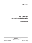
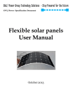
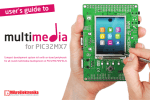
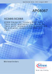
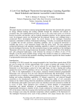
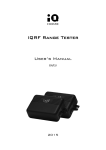
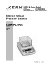
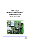
VCP-04
Visual control panel
HW version v1.03
FW version v01.00.01
SW demo version v1.07
User's Guide
© 2013 MICRORISC s.r.o.
www.iqvcp.org
UG_VCP-04_130815
Page 1
VCP-04
Description
VCP-04 is a portable / pocket visual control device with
wireless connectivity and many peripherals for arbitrary use,
fully user customizable / programmable.
It is a generic equipment, i.e. the hardware is fixed and the
user can implement specific functionality by software only.
This device is intended for final production while the DSVCP-04 development set should be used for development.
Key features
• Display/touchscreen 3.5“, 320 x 480 pixels, 262144 colors
• Main MCU PIC32MX7
• Secondary MCU PIC12F615 for basic management
• Micro SD card, serial EEPROM and Flash memories
Applications
• USB device
• Control units for arbitrary use
• Wireless connectivity (IQRF and IR)
• Remote wireless controllers
• Audio output
• Building automation
• RTCC (real time clock/calendar)
• Industrial control
• G-sensor (e.g. for portrait / landscape view switching)
• Access systems
• Light sensor
• Accumulator
• Very low power consumption in Sleep mode
Block diagram
© 2013 MICRORISC s.r.o.
www.iqvcp.org
UG_VCP-04_130815
Page 2
VCP-04
Electrical specifications
(typical values unless otherwise stated)
Power supply
Accumulator
Charging
LIP423885, 3.7 V, 1450 mAh, Li-Pol
5.0 ± 0.35 V DC (via micro USB)
Power consumption
Power-off, all peripherals shut down
Operation, display backlight off
Operation, display backlight on
Accumulator charging
8 µA
150 mA
240 mA
450 mA max.
Display
KWH035ST26-F01-VCP04, TFT LCD 3.5“, 320 x 480 pixels, 256 K colors
Temperature range
Operating
Accumulator charging
Storage
0 °C to +60 °C
0 °C to +45 °C
10 °C to 25 °C recommended
TR module
Frequency range
RF output power
Antenna
RF range
TR-54D, soldered
868 MHz or 916 MHz (SW selectable)
5 dBm (SW selectable in 8 steps, up to specified value)
On-board PCB
430 m
Serial EEPROM endurance
Serial Flash memory endurance
16 Kb, I2C bus, 1 000 000 erase/write cycles (25°C)
8 Mb, SPI bus,100 000 (typ.), 10 000 (min.) erase/write cycles
SD card
Standard 2 GB micro SD
Dimensions
Weight
121.6 mm x 64.5 mm x 11 mm
108 g
Absolute maximum ratings
Stresses above those values may cause permanent damage to the device. Exposure to maximum rating conditions for
extended periods may affect device reliability.
Supply voltage
Storage temperature
© 2013 MICRORISC s.r.o.
5.5 V DC (via micro USB)
-10 °C to +80 °C
www.iqvcp.org
UG_VCP-04_130815
Page 3
VCP-04
Hardware
Power supply
VCP-04 is supplied by the accumulator. It is non-removable, to be charged by 5 V DC via the micro USB connector. Instead
of power off, normal operation can be deactivated by switching to sleep mode.
The accumulator should be protected against total exhausting by application software, switching the device into sleep
mode (see below) when the accumulator voltage is low. The demo software provides this after dropping down to 3.45 V. If
no proper protection is implemented in application SW, VCP-04 forces the sleep mode when the voltage level drops below
2.85 V and wakes up if the voltage rises up again by connecting to external power supply.
Main MCU
VCP-04 is controlled by the 32 b microcontroller PIC32MX795F512L, up to 80 MHz. Main MCU is user programmable.
Program memory size is 512 KB and RAM size is 128 KB.
Secondary MCU
VCP-04 power management, back-up software RTCC and battery monitoring with power source identification are
controlled by the 8b microcontroller PIC12F615MF. Firmware of the secondary MCU is fixed.
Reset pushbutton
VCP-04 reset can be invoked by reset pushbutton accessible by a pin through the hole on the side of the case. This
induces reinitialization of the device.
Sleep mode
Sleep mode is intended to minimize current consumption by disabling internal circuitry. It is possible to wake up from Sleep
by pressing the user pushbutton or by connecting external power source.
RTCC
Real time clock / calendar with crystal precision is implemented in VCP-04. It is operating even in Sleep mode and fails only
if power supply (including the accumulator) fails. Date and time must be set after power on or a reset.
EEPROM memory
EEPROM memory 16 kb, with serial interface I2C, 1 000 000 erase/write cycles.
Serial Flash memory
Flash memory 8 Mb, with serial interface SPI , 100 000 erase/write cycles (typ.).
Micro SD memory card
Standard Flash micro SD memory card with SPI interface. Max. capacity is 2 GB for FAT16 and 2 TB for FAT32. The SD
card is not removable. It is accessible via USB.
Display
Display KWH035ST26-F01-VCP04, 3.5“ diagonal, 320x480 pixels RGB, 262 144 colors VCP TFT LCD, transmissive, with
LED backlight and 16 b parallel data bus is used. Graphic library uses 65 535 colors only.
Backlight
VCP-04 display is illuminated by LEDs. Switching on/off or fading out/in enables to save energy, especially while the device
is powered from the battery.
Touchscreen
A touch within the display area can be detected and localized by integrated resistive touchscreen. Lower part of the
touchscreen creates a touch slider.
© 2013 MICRORISC s.r.o.
www.iqvcp.org
UG_VCP-04_130815
Page 4
VCP-04
Calibration
Proper display functionality requires a calibration (setting the touch sensors in accordance to display pixels) to compensate
variations in parameters due to temperature, tolerance of parts and so on. The VCP-04 has the display factory calibrated.
Calibration values are stored in the EEPROM. A software calibration procedure (3 x 3 touches in locations indicated by an
arrow) is available and should be performed in application software whenever needed (e.g. after significant temperature
change).
Audio
Audio system uses analog as well as digital input and mono output. The functionality is fully under the user's control. It can
be used to generate tones (beeps, alerts, etc.) or to play WAV tracks.
G-sensor
3-axis linear accelerometer can be used e.g. for portrait / landscape view switching.
Illumination sensor
Illumination sensor enables to measure ambient light intensity.
Vibro motor
The coreless permanent magnetic DC motor.
User pushbutton
User pushbutton can be used to control the device. Actual functionality fully depends on application software.
USB
The Universal Serial Bus (USB) module provides a USB 2.0 full-speed and low-speed embedded host, full-speed device, or
OTG implementation. USB OTG enables the intelligence for a device to determine whether it is required to function as a
Host or Peripheral and then configure itself accordingly without any user input.
VCP-04 is capable to function as a Host or Peripheral. The demo SW currently supports USB Peripheral classes only,
either MSD (mass storage device) or CDC (communications device class).
TR module and antenna
Wireless IQRF transceiver module TR-54D, soldered. PCB antenna is integrated on the VCP-04 board.
IR
Infrared wireless module to transmit and receive serial data.
Case
It is not allowed to open the case.
There are two pads on the bottom side of the case reserved for future use (for magnetic fixation to a pod etc.).
Connections
Part
Pins
Connection
Accumulator
2
Soldered
IQRF TR module
18
Soldered
USB
5
Micro USB connector
Micro SD card
10
DM3AT-SF-PEJ (Hirose) connector, inside the case
© 2013 MICRORISC s.r.o.
www.iqvcp.org
UG_VCP-04_130815
Page 5
VCP-04
Programming and debugging
See the DS-VCP-04 User's guide.
Main MCU
Application code can be uploaded to VCP-04 by bootloader (via microUSB cable, with the case closed).
TR module
Application code can be uploaded from PC to the TR module via USB.
Components and controls
© 2013 MICRORISC s.r.o.
www.iqvcp.org
UG_VCP-04_130815
Page 6
VCP-04
Software
Actual functionality of VCP-04 depends on application software in main MCU and in TR module. It should be developed
using the DS-VCP-04 development set and uploaded into VCP-04 by the bootloader.
VCP-04 demo application
VCP-04 is provided with demo program illustrating the following features:
• Display: Rendering of screens
• Touchscreen: User events detections: pressing, releasing, moving
• EEPROM: storing and reading the VCP-04 setting
• Serial Flash memory: storing and reading all graphical elements employed in the demo application
• TR module: SPI master writing and reading, application uploading, module info getting and displaying.
• Infrared module: simple remote controller showing communication with TV Sharp
• Audio module: acoustic indication of touching the screen, predefined tones, WAV reading and playing
• Sensors: G-sensor and illumination level reading and displaying
• SD card: reading and writing, used in many features of the demo application, FAT16, FAT32
• Vibro module: single-shot or repeated vibrations
• Indication LEDs: on, off, toggle and single flash
• Secondary MCU: power management, RTC maintenance, accumulator monitoring
• USB MSD class: Mass Storage Device, makes SD card accessible via USB interface
• USB CDC class: Communications Device Class, creates standard serial port (UART) with echo functionality
• RTCC: date and time setup, autonomous run and displaying
• Sleep mode: to minimize power consumption by „switching off“ the equipment
Refer to software and documentation of the DS-VCP-04 for description of functions and other details.
To implement wireless connectivity, the demo should be operated in the following configuration:
• The tr_vcp04 application uploaded in embedded TR module
• Another (remote) TR module plugged in the DK-EVAL-04 development kit, having the appropriate demo SW uploaded
(iqrf_demo_control or vcp_temp_sensor, see below). Both HEX codes can be downloaded from the VCP-04
product web page.
Complete demo SW including all source codes is available in DS-VCP-04 development set.
© 2013 MICRORISC s.r.o.
www.iqvcp.org
UG_VCP-04_130815
Page 7
VCP-04
Main menu
After wake-up (by the user pushbutton or connecting to external power) the welcome screen appears. Touching the display
brings the main menu with icons. By touching any of the icon the new screen is evoked to demonstrate given functionality
of the particular HW peripheral. To return back to the main menu press the Back button.
Also by touching the screen anywhere off the icons (gray area) and dragging a finger to the left on a touch the screen
scrolls to the left and further icons appear on the screen. The same functionality can be achived by pressing the right arrow
in the lower left side.
Main menu icons
Display
A demonstration shows the TFT display facilities by presenting pictures stored on the SD card in the S_SHOW and IQ_SHOW
folders. Returning back from the Slideshow is up on touching the display and returning from IQRF Slideshow up on
pressing the Back button.
IQRF module
TR module is equipped with dedicated MCU which must have an application software uploaded. The following
functionality is available:
• Wired SPI communication with main MCU (TR module is an SPI slave).
• Wireless bidirectional RF connectivity intended for any remote IQRF device or IQRF wireless network.
• TR module can perform various additional tasks according to user's needs.
If the iqrf_demo_control application is uploaded in remote TR module, the following functionality is implemented: By
pressing the user button on DK-EVAL-04 the LED status on the external TR module is changed and this change is also
reflected on the screen. A content of bufferRF (the TR buffer dedicated to RF communication) is transferred from the
remote TR module and displayed on the screen. By pressing the Turn off the LEDs button both LEDs are switched off and
this change is indicated by switching off the LEDs on the remote TR module.
IQRF upload
A demonstration how to upload a user application into embedded TR module. The TR application in HEX format must be
stored in a file with the .hex extension in the IQUPLOAD folder on the SD card. Just one HEX file is allowed to be stored
there. By pressing the Upload button this application is uploaded into the TR module. When entering the IQRF upload
screen, basic information about embedded TR module such as OS, ID and MCU type is displayed in top part of the screen.
Device info
A demo displaying basic information about the VCP-04 device, such as power source, battery voltage level, presence of SD
card and readings from G-sensor and lighting sensor.
© 2013 MICRORISC s.r.o.
www.iqvcp.org
UG_VCP-04_130815
Page 8
VCP-04
IQRF chat
A demonstration of wireless communication via sending and receiving chat messages. An IQRF packet is considered to be
a chat message if contains the identification.
• Transmitting: A user string can be entered from the keyboard (allowing user predefined symbols) to the Tx field and sent
by the TR module as an RF chat message by pressing the Send button.
• Receiving: Embedded TR module continually listens to incoming RF packets. If a correct chat message is detected, the
received text is displayed in the Rx field.
This demo works if the tr_vcp04 application is uploaded in the embedded TR module.
Temp sensor
A demonstration of wireless communication via receiving messages from external TR module measuring temperature and
battery level. This demo works if the vcp_temp_sensor application is uploaded in remote TR module.
Embedded TR module continually listens to incoming RF packets. If a correct message is detected, the received values are
displayed on the screen.
Infrared module
A demo example of a remote IR controller utilizing the communication protocol defined by Sharp. Whenever the button is
pressed the predefined message is sent. If the button is held pressed the message is sent repeatedly until the button is
released. To control the volume, the touch scrollbar located in bottom part of the device
is intended. The volume is proportional to the position on the scrollbar. Only sending
feature is currently supported by IR module.
RGB editor
A useful tool for selection of colors. Select one from the three RGB primary colors. The
buttons display their levels. Current color can be set by selecting particular color field
and then by using the touch scrollbar. The resulting color is displayed also as a numeric
code.
Audio
A demo for audio operation. Audio files should be placed in the SOUNDS folder on the SD card. This demo supports also
playing an audio file from internal Flash memory of main MCU. Due to space saving, it is recommended just for a short
audio track. Audio library supports WAV files without compression. VCP-04 allows to play audio samples with rates from 8
kHz to 48 kHz and from 8 to 32 bit resolution. The golden mean 32 kHz sample rate and 16 bit resolution is recommended
as optimal.
Basic control for OPEN, PLAY, STOP and a Volume setting is implemented. The volume is set by touching the scrollbar
located at the bottom part of the device. The short sound track played immediately after pressing the PLAY button
demonstrates the capability of reading and playing audio data from internal Flash memory.
Sleep
It allows to put the device in sleep (standby) mode. This screen can be also accessed by holding the user button pressed
not longer than 2 s. Device can be woken up upon pressing user button or connecting external power source.
Vibro module
It demonstrates the capability of vibration module. Single-shot and repeated vibrations are supported.
SD card
A demo for initialization of the SD card and test access to the card by reading and writing a text message to the file.
GW_FILE.txt is used for reading and writing tests.
The SD card connector is equipped with a contact to detect whether the card is inserted. This contact is checked and the
following message is issued:
• Contact: Error – the contact is open
• Contact: OK – the contact is switched
If no SD card is inserted the message „SD card not inserted“ is issued.
About
A screen displaying FW version of the demo application and additional information about company and product web pages.
© 2013 MICRORISC s.r.o.
www.iqvcp.org
UG_VCP-04_130815
Page 9
VCP-04
Pushbutton (PB1)
Three kinds of presses are distinguished by the demo:
• Short (< 2 s): Quick access to the Sleep screen.
• Long (> 2 s): Creating a screenshot and storing it as the BMP file on the SD card in the S_SHOT folder. To update the
file system in order to access the newly created file on the SD card via USB, the USB cable must be
unplugged from and pluged to PC again. Saving of the file is indicated by faster LED blinking.
• Long (> 10 s): The Factory Setup procedure for restoring of initial default values (display backlight, acoustic
indication and USB class) and for display calibration.
LED indication
A demo illustrating VCP-04 state indication:
• Operation, external power: Green LED (LEDG) flashing
• Operation, powered from accumulator : Red LED (LEDR) flashing
Settings
Time & Date
It allows to set the time and date of software RTCC clock in main MCU and synchronize it with RTC clock in secondary
MCU. Select desired item and then set a new value by pressing the Up and Down arrows. The RTCC clock is initialized
from secondary MCU each time the demo application starts.
Display
It allows to set the period for switching the display backlight off in case of no activity. The setting is individual for both power
sources (external / accumulator). The setting is stored in EEPROM. The backlight is switched on by touching the display or
by the pushbutton.
Sound
Switching the acoustic indication of touching the screen on/off. The setting is stored in EEPROM.
USB classes
Allows to switch among different supported USB classes. To change the class only reinicialization of USB system of the
device is necessary. The setting is stored in EEPROM.
Supported USB classes:
• Mass storage (default)
After the VCP-04 is connected, the internal micro SD card is accessed like an additional PC disk. This selection is
allowed if the SD card is plugged only.
• CDC Class
Creates a virtual serial COM port. The user can use a suitable PC terminal or create his own PC program to communicate
via this port.
Demo application uses the COM settings 9600, 8, none, 1 and operates as follows:
If the "i" character is sent from the PC terminal, VCP-04 returns the device identification in text format.
Tip
For a communication in CDC mode various SW terminals operating with PC serial ports are available. Select a terminal
enabling to issue direct byte commands and data.
Recommended terminal: Docklight, www.docklight.de
Unsuitable terminal: Windows Hyperterminal and Tera Term.
© 2013 MICRORISC s.r.o.
www.iqvcp.org
UG_VCP-04_130815
Page 10
VCP-04
Product information
Pack list
• VCP-04, in Sleep mode
• Demo application and the bootloader uploaded in main MCU
• The tr_vcp04 demo application uploaded in embedded TR module, RFPGM after reset disabled
• TR module and SD card 2 GB included
• Accumulator (soldered)
• Power source TY-A6A (5V DC, 500 mA, stabilized, cordless, with USB A connector)
• Micro USB cable CAB-USBABMICRO
• Brief User's manual
Ordering codes
• VCP-04
• DS-VCP-04
Visual control panel (for final production)
Development set for VCP-04 (for development)
Document history
• 130815
• 130725
© 2013 MICRORISC s.r.o.
Bug in display type on page 3 fixed.
First release.
www.iqvcp.org
UG_VCP-04_130815
Page 11
VCP-04
Sales and Service
Corporate office
MICRORISC s.r.o., Prumyslova 1275, 506 01 Jicin, Czech Republic, EU
Tel: +420 493 538 125, Fax: +420 493 538 126, www.microrisc.com
Partners and distribution
Please visit www.iqrf.org/partners
Quality management
ISO 9001 : 2009 certified
Complies with Directive 2002/95/EC (RoHS)
Trademarks
The IQRF name and logo and MICRORISC name are registered trademarks of MICRORISC s.r.o.
PIC, SPI, Microchip and all other trademarks mentioned herein are property of their respective owners.
Legal
All information contained in this publication is intended through suggestion only and may be superseded by updates
without prior notice. No representation or warranty is given and no liability is assumed by MICRORISC s.r.o. with respect to
the accuracy or use of such information.
Without written permission it is not allowed to copy or reproduce this information, even partially.
No licenses are conveyed, implicitly or otherwise, under any intellectual property rights.
The IQRF ® products utilize several patents (CZ, EU, US)
On-line support: [email protected]
© 2013 MICRORISC s.r.o.
www.iqvcp.org
UG_VCP-04_130815
Page 12