1
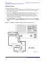
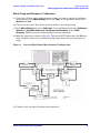
General Overview
Making High Power Measurements With Option H85
E8362B, E8363B and E8384B Option H85
18. Calculate the amount of attenuation needed between the analyzer's coupler and
receivers so that you do not exceed the optimum receiver power level of –12 dBm.
It will be necessary to take the following into consideration:
• Receiver A will be coupled to the analyzer RF path that could receive power reflections
as high as +10 dBm.
• Receiver B will be coupled to the analyzer RF path that could receive a maximum of
+20 dBm from the DUT.
• Analyzer coupler loss is –13 dB.
• The optimum receiver power level is –12 dBm.
19. Set the internal step attenuator to the value calculated below (rounding off to the
highest 5 dB step). Setting the receiver attenuation will set the internal attenuation.
Press [Menu/Dialog] then tab to Channel. In the pull down menu select Power, under
Receiver Attenuation set Receiver A to [10] and Receiver B to [20]. Power levels greater
than +35 dBm will require additional attenuation between Port 2 access ports CPLR
ARM and RCVR B IN, see Figure 8.
With the previous points in mind, the amount of attenuation can be calculated from the
following equations:
Receiver Attenuator A = 10dBm – 13dBm – ( – 12dBm )
Attenuator A = 10dBm
Receiver Attenuator B = 20dBm – 13dBm – ( – 12dBm )
Attenuator B = 20dBm
20. Turn on the booster amplifier.
CAUTION
From this point forward, do not press Preset unless you have turned off the
booster amplifier(s), or you have saved this state and renamed it to User
Preset. Pressing Preset will return the analyzer to its default power level and
default internal attenuator settings. This increase in power may result in
damage to the DUT or analyzer.
21. Press [Menu/Dialog] to activate the R1 Input Path then tab to Channel. In the pull
down menu select Test Set. A window for the R1 Input Path will be displayed. Select
the External R1 Loop.
22. Measure the output power from the Test Port 1 using a power meter and verify that it
is as you would expect.
If you are measuring a highly reflective device, high power isolators should be inserted
between the 20 dB coupler and CPLR THRU front panel ports.
14
User’s and Service Guide Supplement