1
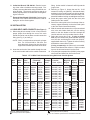
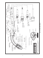
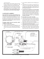
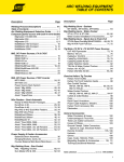
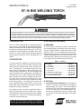
F11-744-R
INSTRUCTIONS for
September, 2004
ST-16 MIG WELDING TORCH
These INSTRUCTIONS are for experienced operators. If you are not fully familiar with the principles of operation and safe practices for
arc welding equipment, we urge you to read our booklet, "Precautions and Safe Practices for Arc Welding, Cutting, and Gouging,"
Form 52-529. Do NOT permit untrained persons to install, operate, or maintain this equipment. Do NOT attempt to install or operate
this equipment until you have read and fully understand these instructions. If you do not fully understand these instructions, contact
your supplier for further information. Be sure to read the Safety Precautions before installing or operating this equipment.
I. INTRODUCTION
III. ACCESSORY EQUIPMENT
The ST-16 Torch, P/N 997498, is a rugged all purpose,
water cooled, manual Mig welding torch designed to
operate at welding currents up to 600 amperes continuous duty using argon as the shielding gas. The ST-16 is
intended for use with ESAB wire feeders which have
provision for water cooling and will handle all types of
welding wires in sizes from .030-in. through 7/64-in. diameter.
A. REQUIRED
II. DESCRIPTION
The ST-16 requires a nozzle (see Table 1), and several
wire feed accessories of the proper size for the wire being used. (Refer to Table 2 if using the self-lined conduit
system or Table 3 if using conduit with continuous or
replaceable liner system). One other accessory whose
selection depends upon wire size is the feed roll on the
wire feeder itself. Selection of this accessory is covered
in the appropriate wire feeder instruction booklet.
Table 1 - Nozzles
To provide maximum resistance to the abuses of day to
day service, the torch is of heavy-duty construction with
metal parts well insulated from current carrying members. It’s 55-degree, curved stainless steel front body
permits effective operation in tight, hard-to-reach corners and other contained areas. The torch employs metal
nozzles and either slip-in contact tubes or threaded contact tips (long or short). Each contact tube is threadless
and is retained by a collet nut supplied with the torch.
All service lines are internally connected to the torch
body and exit from the rear of the torch handle for easy
torch maneuverability. For weld start-stop control, the
torch is provided with a positive action universal lever
switch which can be positioned at any point on the torch
handle preferred by the operator.
For feeding all wires, a self-lined conduit with either a
spring or plastic jumper liner is normally used. An alternate replaceable liner conduit system is also available
for feeding 0.35, .045 and 1/16-in. hard wires through a
continuous metal conduit liner.
Be sure this information reaches the operator.
You can get extra copies through your supplier.
Description
Part No.
No. 8 Nozzle ....................................... P/N 598739*
No. 10 Nozzle ...................................... P/N 598721*
No. 10L Nozzle .................................... P/N 598891
No. 12 Nozzle ...................................... P/N 633985
No. 12M Med. Length Nozzle ............... P/N 997310
No. 12L Long Length Nozzle ................ P/N 639756
No. 12 Spot Welding Nozzle ................ P/N 993757
* Requires Spatter Liner, P/N 633603
B. OPTIONAL
1. Centering Bushing, P/N 994330 (For use with No.8
and No. 10 nozzles) - Eliminates any possibility of
spatter bridging in the torch. This is accomplished
by using this one-piece centering bushing and spatter liner in place of the two individual pieces normally used. Note that it can only be used at maximum current of 350 amps with argon or 550 amps
with C02.
USER RESPONSIBILITY
This equipment will perform in conformity with the description thereof contained in this manual and
accompanying labels and/or inserts when installed, operated, maintained, and repaired in accordance
with the instructions provided. This equipment must be checked periodically. Malfunctioning or poorly
maintained equipment should not be used. Parts that are broken, missing, worn, distorted, or contaminated should be replaced immediately. Should such repair or replacement become necessary, the manufacturer recommends that a telephone or written request for service advice be made to the Authorized
Distributor from whom purchased.
This equipment or any of its parts should not be altered without the prior written approval of the
manufacturer. The user of this equipment shall have the sole responsibility for any malfunction which
results from improper use, faulty maintenance, damage, improper repair, or alteration by anyone other
than the manufacturer or a service facility designated by the manufacturer.
2
SAFETY PRECAUTIONS
WARNING: These Safety Precautions are for
your protection. They summarize precautionary
information from the references listed in Additional Safety Information section. Before performing any installation or operating procedures, be sure to
read and follow the safety precautions listed below as well as
all other manuals, material safety data sheets, labels, etc.
Failure to observe Safety Precautions can result in injury or
death.
5. Do not use equipment beyond its ratings. For example,
overloaded welding cable can overheat and create a fire
hazard.
6. After completing operations, inspect the work area to make
certain there are no hot sparks or hot metal which could
cause a later fire. Use fire watchers when necessary.
7. For additional information, refer to NFPA Standard 51B,
"Fire Prevention in Use of Cutting and Welding Processes",
available from the National Fire Protection Association,
Batterymarch Park, Quincy, MA 02269.
PROTECT YOURSELF AND OTHERS -Some welding, cutting, and gouging
processes are noisy and require ear
protection. The arc, like the sun, emits
ultraviolet (UV) and other radiation and
can injure skin and eyes. Hot metal can cause burns.
Training in the proper use of the processes and equipment is essential to prevent accidents. Therefore:
ELECTRICAL SHOCK -- Contact with live
electrical parts and ground can cause
severe injury or death. DO NOT use AC
welding current in damp areas, if movement is confined, or if there is danger of
falling.
1. Be sure the power source frame (chassis) is connected to
the ground system of the input power.
2. Connect the workpiece to a good electrical ground.
3. Connect the work cable to the workpiece. A poor or
missing connection can expose you or others to a fatal
shock.
4. Use well-maintained equipment. Replace worn or damaged cables.
5. Keep everything dry, including clothing, work area, cables,
torch/electrode holder, and power source.
6. Make sure that all parts of your body are insulated from
work and from ground.
7. Do not stand directly on metal or the earth while working
in tight quarters or a damp area; stand on dry boards or an
insulating platform and wear rubber-soled shoes.
8. Put on dry, hole-free gloves before turning on the power.
9. Turn off the power before removing your gloves.
10. Refer to ANSI/ASC Standard Z49.1 (listed on next page)
for specific grounding recommendations. Do not mistake
the work lead for a ground cable.
1. Always wear safety glasses with side shields in any work
area, even if welding helmets, face shields, and goggles
are also required.
2. Use a face shield fitted with the correct filter and cover
plates to protect your eyes, face, neck, and ears from
sparks and rays of the arc when operating or observing
operations. Warn bystanders not to watch the arc and not
to expose themselves to the rays of the electric-arc or hot
metal.
3. Wear flameproof gauntlet type gloves, heavy long-sleeve
shirt, cuffless trousers, high-topped shoes, and a welding
helmet or cap for hair protection, to protect against arc
rays and hot sparks or hot metal. A flameproof apron may
also be desirable as protection against radiated heat and
sparks.
4. Hot sparks or metal can lodge in rolled up sleeves, trouser
cuffs, or pockets. Sleeves and collars should be kept
buttoned, and open pockets eliminated from the front of
clothing
5. Protect other personnel from arc rays and hot sparks with
a suitable non-flammable partition or curtains.
6. Use goggles over safety glasses when chipping slag or
grinding. Chipped slag may be hot and can fly far. Bystanders should also wear goggles over safety glasses.
ELECTRIC AND MAGNETIC FIELDS — May be dangerous.
Electric current flowing through any
conductor causes localized Electric and
Magnetic Fields (EMF). Welding and cutting current creates EMF around welding cables and welding machines. Therefore:
FIRES AND EXPLOSIONS -- Heat from
flames and arcs can start fires. Hot slag
or sparks can also cause fires and explosions. Therefore:
1. Remove all combustible materials well away from the work
area or cover the materials with a protective non-flammable covering. Combustible materials include wood,
cloth, sawdust, liquid and gas fuels, solvents, paints and
coatings, paper, etc.
2. Hot sparks or hot metal can fall through cracks or crevices
in floors or wall openings and cause a hidden smoldering
fire or fires on the floor below. Make certain that such
openings are protected from hot sparks and metal.“
3. Do not weld, cut or perform other hot work until the
workpiece has been completely cleaned so that there are
no substances on the workpiece which might produce
flammable or toxic vapors. Do not do hot work on closed
containers. They may explode.
4. Have fire extinguishing equipment handy for instant use,
such as a garden hose, water pail, sand bucket, or portable fire extinguisher. Be sure you are trained in its use.
1. Welders having pacemakers should consult their physician
before welding. EMF may interfere with some pacemakers.
2. Exposure to EMF may have other health effects which are
unknown.
3. Welders should use the following procedures to minimize
exposure to EMF:
A. Route the electrode and work cables together. Secure
them with tape when possible.
B. Never coil the torch or work cable around your body.
C. Do not place your body between the torch and work
cables. Route cables on the same side of your body.
D. Connect the work cable to the workpiece as close as
possible to the area being welded.
E. Keep welding power source and cables as far away from
your body as possible.
3
11/95
EQUIPMENT MAINTENANCE -- Faulty or
improperly maintained equipment can
cause injury or death. Therefore:
FUMES AND GASES -- Fumes and
gases, can cause discomfort or harm,
particularly in confined spaces. Do
not breathe fumes and gases. Shielding gases can cause asphyxiation.
Therefore:
1. Always have qualified personnel perform the installation,
troubleshooting, and maintenance work. Do not perform
any electrical work unless you are qualified to perform
such work.
2. Before performing any maintenance work inside a power
source, disconnect the power source from the incoming
electrical power.
3. Maintain cables, grounding wire, connections, power cord,
and power supply in safe working order. Do not operate
any equipment in faulty condition.
4. Do not abuse any equipment or accessories. Keep
equipment away from heat sources such as furnaces, wet
conditions such as water puddles, oil or grease, corrosive
atmospheres and inclement weather.
5. Keep all safety devices and cabinet covers in position and
in good repair.
6. Use equipment only for its intended purpose. Do not
modify it in any manner.
1. Always provide adequate ventilation in the work area by
natural or mechanical means. Do not weld, cut, or gouge
on materials such as galvanized steel, stainless steel,
copper, zinc, lead, beryllium, or cadmium unless positive
mechanical ventilation is provided. Do not breathe fumes
from these materials.
2. Do not operate near degreasing and spraying operations.
The heat or arc rays can react with chlorinated hydrocarbon vapors to form phosgene, a highly toxic gas, and
other irritant gases.
3. If you develop momentary eye, nose, or throat irritation
while operating, this is an indication that ventilation is not
adequate. Stop work and take necessary steps to improve
ventilation in the work area. Do not continue to operate if
physical discomfort persists.
4. Refer to ANSI/ASC Standard Z49.1 (see listing below) for
specific ventilation recommendations.
5. WARNING: This product, when used for welding or
cutting, produces fumes or gases which
contain chemicals known to the State of
California to cause birth defects and, in
some cases, cancer. (California Health &
Safety Code §25249.5 et seq.)
ADDITIONAL SAFETY INFORMATION -- For
more information on safe practices for electric arc welding and cutting equipment, ask
your supplier for a copy of "Precautions and
Safe Practices for Arc Welding, Cutting and
Gouging", Form 52-529.
The following publications, which are available from the
American Welding Society, 550 N.W. LeJuene Road, Miami,
FL 33126, are recommended to you:
1. ANSI/ASC Z49.1 - "Safety in Welding and Cutting"
2. AWS C5.1 - "Recommended Practices for Plasma Arc
Welding"
3. AWS C5.2 - "Recommended Practices for Plasma Arc
Cutting"
4. AWS C5.3 - "Recommended Practices for Air Carbon Arc
Gouging and Cutting"
5. AWS C5.5 - "Recommended Practices for Gas Tungsten
Arc Welding“
6. AWS C5.6 - "Recommended Practices for Gas Metal Arc
Welding"“
7. AWS SP - "Safe Practices" - Reprint, Welding Handbook.
8. ANSI/AWS F4.1, "Recommended Safe Practices for Welding and Cutting of Containers That Have Held Hazardous
Substances."
CYLINDER HANDLING -- Cylinders, if
mishandled, can rupture and violently
release gas. Sudden rupture of cylinder, valve, or relief device can injure or
kill. Therefore:
1. Use the proper gas for the process and use the proper
pressure reducing regulator designed to operate from the
compressed gas cylinder. Do not use adaptors. Maintain
hoses and fittings in good condition. Follow manufacturer's
operating instructions for mounting regulator to a compressed gas cylinder.
2. Always secure cylinders in an upright position by chain or
strap to suitable hand trucks, undercarriages, benches,
walls, post, or racks. Never secure cylinders to work tables
or fixtures where they may become part of an electrical
circuit.
3. When not in use, keep cylinder valves closed. Have valve
protection cap in place if regulator is not connected.
Secure and move cylinders by using suitable hand trucks.
Avoid rough handling of cylinders.
4. Locate cylinders away from heat, sparks, and flames.
Never strike an arc on a cylinder.
5. For additional information, refer to CGA Standard P-1,
"Precautions for Safe Handling of Compressed Gases in
Cylinders", which is available from Compressed Gas Association, 1235 Jefferson Davis Highway, Arlington, VA
22202.
MEANING OF SYMBOLS - As used throughout this manual: Means Attention! Be Alert!
Your safety is involved.
Means immediate hazards which, if not
avoided, will result in immediate, serious personal injury or loss of life.
Means potential hazards which could
result in personal injury or loss of life.
Means hazards which could result in
minor personal injury.
4
SP98-10
2. Collet Nut Wrench, P/N 996109 - Permits loosening of the collet nut without removing nozzle. Particularly recommended when using the 994330 centering bushing. The wrench employes a stop-pin to
assure proper position of contact tube when tightening the collet nut.
3. Zippered Hose Sheath, P/N 41V98 - Reduces abrasive wear of the cables and eliminates the need for
taping the service lines together.
3.
4.
5.
IV. INSTALLATION
6.
A. USING SELF-LINED CONDUITS (See Figure 1)
1. When using all wire except 7/64-in. cored, insert the
proper jumper liner through the rear of the torch
handle and as far into the brass conduit connection
fitting (see Fig. 3) as it will go.
7.
NOTE: 7/64-in. cored wire does not require a jumper
liner. For .035 and 3/64-in. soft wires, first
insert the plastic jumper liner into the spring
support liner and then place both in the torch.
2. Insert the torch end of the conduit through the rear
of the torch handle and into the conduit connection
8.
fitting. As the conduit is inserted it will fully seat the
jumper liner.
Referring to Figure 3, loosen the two No. 10-32
screws on locking nut (598787), slide handle back,
and then lock the conduit in place by locking the No.
10-32 setscrew on the conduit connection fitting. Reassemble handle to locking nut and tighten setscrews.
Screw the proper outlet guide into the drive (wire
feeder) and of the conduit.
Secure the outlet guide in the front clamp of the accessory support assembly on the wire feeder (refer
to the wire feeder instruction booklet).
With the nozzle and contact tube or tip removed and
wire in the wire feeder feed rolls, use the inching
switch on the wire feeder to feed wire through the
conduit and torch until it protrudes from the torch.
Select the correct tube ot tip. If using a contact
tube, slip the contact tube (small diameter end first)
over the wire and through the collet nut (632811,
supplied with the torch). Tighten the collet nut firmly
and hold the contact tube in place.
If using a contact tip, the collet nut is not needed.
Remove and discard the collet nut. Slip the contact
tip over the wire and screw it into the torch.
If required, place a spatter liner (633603) in the proper
size nozzle and install into front end of torch.
Table 2 - ST-16 Wire Feed Accessories Using Self-Lined Conduit System
Wire
Size
Contact
Tube
(Slip-in)
Hard
.030
.035
.040
.045
.052
1/16
5/64
3/32
996104
37277
37280*
996816*
37283*
37285*
996108*
20123
632794
37276
37279*
632796
37282*
-
Cored
.030
.035
.040
.045
.052
1/16
5/64
3/32
7/64
996104
37277
37280*
996816*
37283*
37285*
996108
-
Soft
.035
.040
3/64
1/16
3/32
996104
37277
996105
996106
Wire
Type
Contact Tip
(Threaded)
Long
Short
Jumper
Liner
Soft-Lined
Conduit
10-ft.. x (I.D.)
Wire Outlet Guide
Mig-31A, Mig-35
Digimig
Mig-34
632791
632793
37275
37278*
632795
37281*
37284*
632800*
993822
993822
993822
993823
993923
993823
993823
598927
633455 (.063)
633455 (.063)
633455 (.063)
633456 (.093)
633456 (.093)
633456 (.093)
633456 (.093)
598922 (.195)
993859
993859
993859
04N19
04N19
04N19
-
993860
993860
993860
39N15
39N15
39N15
39N15
62N17
-
20123
632794
37276
37279*
632796*
37282*
-
632791
632793
37275
37278*
632795*
37281*
37284*
632800
633611
993822
993822
993822
993823
993823
598927
598927
598927
-
633455 (.063)
633455 (.063)
633455 (.063)
633456 (.093)
633456 (.093)
598806 (.140)
598806 (.140)
598922 (.195)
598922 (.195)
993859
993859
993859
04N19
04N19
04N19
2075247
-
993860
993860
993860
39N15
39N15
39N15
62N17
62N17
39N16
-
632794
37276
632796
632798
-
632793
37275
632795
632797
632800
636877
636877
636877
636879
994552
633578 (.060)
633578 (.060)
633578 (.060)
634777 (.093)
46V68 (.128)
05N56
05N56
05N56
05N56
-
29N13
29N13
29N13
29N13
29N13
993902
993902
05N57
12N75
05N58
Spring support liner (598927) is also required.
Use No. 12M Nozzle (P/N 997310).
Includes replacement sleeve (995651).
*
5
Outlet
Guide
Insert
Includes replacement sleeve (995692).
Includes replacement sleeve (995693).
New I.D. for better arc permfrmance on hard and flux cored wire.
6
SELF-LINED CONDUIT
JUMPER LINER
Fig. 1 - Installation of Wire Feed Accessories Using Self Lined Conduit System
* Discard collet nut if using threaded contact tip.
CONTACT TUBE OR TIP
SPATTER LINER
COLLET NUT - 632811*
CONDUIT
(For all hard and cored wire)
SPRING JUMPER LINER
(For all soft wire)
PLASTIC JUMPER LINER
SOFT
GUIDE
INSERT
WIRE OUTLET GUIDE
HARD and CORED
SLEEVE
WIRE OUTLET GUIDE
Mig-35
Table 3 - ST-16 Wire Feed Accessories Using Conduit/Replaceable Liner System
Contact
Tube
(Slip-in)
Contact Tip
(Threaded)
Long
Short
Hard
996104
996105
996816
996106
632794
632796
948335
632798
Cored
996105
996816
996816
Wire
Type/
Size
-
Soft-Lined
Conduit
10-ft.. x (I.D.)
Replaceable
Spring
Liner
Wire Outlet Guide
Mig-35
Digimig
632793
632795
948308
632797
598922 (.195)
598922 (.195)
598922 (.195)
598922 (.195)
636843
598786
598786
598786
29N13
29N13
29N13
29N13
632795
948308
632797
598922 (.195)
598922 (.195)
598922 (.195)
598786
598786
598786
29N13
29N13
29N13
Use No. 12M Nozzle (P/N 997310).
Specific operation of the torch depends on the particular
wire feeder with which it is used. Therefore, consult the
instruction manual supplied with the wire feeder.
B. USING CONDUITS WITH REPLACEABLE LINERS
1. Insert the torch end of the conduit through the rear
of the torch handle and into the conduit connection
fitting.
2. Refering to Figure 3, loosen the two No. 10-32 screws
on locking nut (598787), slide handle back, and then
lock the conduit in place by tightening the No. 10-32
setscrew on the conduit connection fitting. Reassemble handle to locking nut and tighten setscrews.
3. Insert the liner into the conduit and through the torch.
The shoulder spring about the liner should rest inside and below the threads of the wire feeder end of
the conduit.
4. Slip the wire outlet guide (see Table 3) over the liner
protruding from the conduit and screw into the conduit connection. If necessary, adjust shoulder spring
on liner so that the end of the liner is about flush with
the end of the wire outlet guide.
5. Complete the installation by following steps 5 through
8 as described on page 5 , (Section IV, Using SelfLined Conduits).
VI. MAINTENANCE
If this equipment does not operate properly, stop
work immediately and investigate the cause of the
malfunction. Maintenance work must be performed
by an experienced person, and electrical work by a
trained electrician. Do not permit untrained persons
to inspect, clean, or repair this equipment. Use only
recommended replacements.
A. POWER CABLE
If the power cable assembly becomes damaged, it is
recommended that (1) a new one be purchased, or (2)
the damaged unit be turned over to an ESAB authorized
repair station for repair. The connection fittings are
crimped on at the factory by special crimping tools to
ensure strong connections and prevent leakage. A satisfactory job cannot be done without these tools.
V. ADJUSTMENT & OPERATION
B. GAS AND WATER HOSE ASSEMBLIES
(Refer to Fig. 3)
If shielding gas (46V63) or water hose assemblies
(46V25) require replacement, loosen the two No. 10-32
x 3/16-in. set screws on the handle locking nut and pull
handle back.
Before adjustments are made, disengage the pessure
roll to prevent wire from feeding and arcing to an
accidental ground.
To replace gas hose assembly, proceed as follows:
1. Clip off wire hose clamp (53N46) and remove hose.
2. Clean off fitting, and then brush on some Loctite
Prism 447 (P/N 71201202 - 20 gm tube) onto the
fitting.
3. Slide new wire hose clamp on the new hose and
insert the hose over the grooved sealing area of the
hose fitting on the torch.
3. Using a pair of pliers, pull on the hose clamp tightly
over the grooved sealing surface and apply 1/2 twist.
Be sure to position the wire hose clamp so that the
To set the shielding gas flow rate, press the torch lever
to open the gas solenoid valve and adjust the flowmeter
to the desired flow rate. For proper operation a minimun
flow of .40 gpm of cooling water at 60-deg.F or less,
must be maintained if the torch is to perform at rated
capacity. A torch inlet water pressure of 25 psi minimum
will provide adequate flow. Check these water flow requirements before starting. The wire feed conduit should
be kept as straight as possible and without sharp bends
to assure smoother wire feed.
7
twist does not interfere with another part or the inside of the handle.
5. Reposition the pliers about 1/8-in. from the hose and
twist an additional 1-1/2 turns.
6. Snip off excess wire about 1/8-in. from hose and
bend the twisted ends as shown below.
D. CENTERING BUSHING
(Refer to Figs. 2 &3)
To remove the centering bushing (17782) for inspection
or replacement, first shut off power source and then remove nozzle, contact tube, and collet nut. Insert the
centering bushing removal tool (996300, supplied with
the torch) through two adjacent bushing slots and then
hook over two opposite bushing ribs. The centering bushing can then be removed by pulling the tool straight out.
If centering bushing is wedged against the nozzle body,
do the following:
1. Loosen the two No. 10-32 handle locking screws and
pull back handle enough to clear the locking nut
(598787).
2. Holding nozzle body (598885), loosen locking nut at
least one turn.
3. Remove centering bushing as described above.
To replace the water hose assembly proceed as follows:
1. Snip off the ear of the hose clamp by cutting into the
sides with pincers.
2. Clean off barbed fitting, and then brush on some
Loctite Prism 447 (P/N 71201202-20gm tube) onto
the fitting.
3. Slide the hose clamp over the hose.
4. Push hose into the short water connection tube of
the torch body and tube assembly. Position the hose
clamp over the grooved section of the short tube.
5. Crimp the ear of the hose clamp with pincers.
6. Rotate the hose clamp so the ear is positioned close
to the power connection tube as shown in Section
“A-A” of Figure 3.
E. TORCH GAS SHIELDING
(Refer to Figs. 2 &3)
Excellent gas coverage is assured by laminar gas flow
techniques and efficient cooling. Any water leakage into
the gas stream area, however slight, will disturb gas
coverage and weld quality. If gas coverage falls below
the desired level, tighten the torch locking nut a quarter
turn, purge the torch with shielding gas for a moment
and return to service. If this does not correct the condition, the entire body and tube assembly should be removed to permit clearing the internal components of any
collected spatter particles and then reassembling.
C. NOZZLES
Adherence of spatter can be minimized and removal
made easier by coating the inside of the nozzle with No.
65 Nozzle Compound (4-oz. container - 08N65; 1 quart
container - 08N75). If insulator liner is damaged or
cracked it should be replaced.
F. GASKET AND END FITTING
(Refer to Figs. 2 &3)
To remove gasket (633884) or wire guide and fitting
(996403) for replacement or inspection purposes, proceed as follows:
(2) SETSCREW
1. With power source turned off, disconnect all torch
service lines.
2. Remove nozzle, contact tube and collet nut.
3. Loosen the two setscrews on locking nut (598787)
and pull back torch handle (lever switch attached)
enough to allow locking nut to rotate freely.
4. Unscrew the locking nut from the nozzle body
(598885)
5. Pull the nozzle body away from wire guide assembly (997027). The centering bushing (17782) will
fall free at this point.
6. Check the gasket for cracks and deformed sealing
surfaces. When replacing the old, or installing a new
gasket, apply a thin film of silicone grease (17672)
to the O.D. and sealing surfaces of the gasket.
7. To remove the wire guide end fitting (996403), clamp
the curved wire guide assembly and then unscrew
the end fitting using a 7/16-in. open-end wrench (note
that the end fitting and wire guide are connected via
a 1/8”-27 tapered pipe thread). (Continued on page 10).
GASKET SEAL
HANDLE
WIRE GUIDE
ASSEMBLY
LOCKING
NUT
INSULATOR SLEEVE
END FITTING
NOZZLE BODY
ASSEMBLY
CENTERING BUSHING
Fig. 2 - Exploded View of Torch
8
9
(Accessory - see Table 1)
SPATTER LINER
NOZZLE (Accessory - see Table 1)
COLLET NUT - 632811
996300
Hand tighten locking nut 598787; then another 3/16”
to 1/4” turn with a wrench (approx 125-in.lbs.)
SUPPLIED
CENTERING BUSHING
REMOVAL TOOL
SWITCHCORD
POWER AND WATER OUT
Fig. 3 - ST-16 Torch, P/N 997498
SECTION “A” - “A’
WATER IN
GAS
CONDUIT
(See Figure 4)
Conduit Connection Fitting
SCREW - 10-32 X 3/16
6133-0907 (Supplied with 997027)
RUBBER BAND - 595958
SHIELGING GAS HOSE
ASSEM. - 46V63
(12 FT.)
SWITCHCORD ASSEMBLY
5/8“ - 18
7/8 - 14 L.H.
WATER HOSE
ASSEM. - 46V25
(12 FT.)
5/8“ - 18 L.H.
HOSE CLAMP
950626
HANDLE
598738
POWER CABLE
ASSEM. - 598928
(12 FT.)
(See Fig. 4)
(Supplied with 997027)
CENTERING BUSHING - 17782
LEVER SWITCH & CORD
ASSEM. - 996356
“A”
“A”
LOCKING NUT
598787
END FITTING. - 996403
SCREW - 10-32 X 3/16
6133-0907
CONTACT TUBE (Accessory - see Table 2 & Section IV-7)
1/8” - 27
TAPERED
PIPE THRD.
WIRE GUIDE, BODY &
TUBE ASSEM. - 997027
NOZZLE BODY
ASSEM. - 598885
GASKET - 633884
INSULATOR SLEEVE - 633880
(Continued from page 8).
3. Lift out switch (181W34) from the locating lugs on
body.
4. If replacing the micro switch only, unsolder the connections. Do not snip off the leads. Replace switch
by soldering the black lead (or longer lead) to the
normally open terminal (NO) and the white lead to
the common terminal (C).
5. If cord removal is necessary or if cord and switch
assembly is being replaced, use 5/64-in. hex socket
wrench and loosen set screw (6133-0876). The brass
strain relief (61N67) may be wedged in the body. If
wedged, hit the strain relief through the slotted opening of the body with a screwdriver. This should free
the strain relief and the switch and cord assembly
can then be removed.
Before installing a new end fitting, apply a thin film
of Dow Corning Heat Sink Compound No. 340
(73585976) to both the male and female threads.
8. Reassemble the torch in reverse order. When reassembling, tighten the lock nut hand tight, and then
tighten another 3/16 to 1/4 of a turn (approx. 125 in.lbs.) with a wrench. This should provide enough loading on gasket to prevent water and gas leakages.
G. LEVER SWITCH ASSEMBLY
If part replacement on the lever switch assembly is necessary, refer to Fig. 4 and seperate the two halves of the
switch body by removing the two slotted No. 8-32 x 3/8in. screws. Then proceed as directed below. You can
pull back the rubber band off the torch handle and cut
the plastic tape wrappings about the service lines for
convenience but it is not necessary unless the switchcord
replacement is also involved
To reassemble lever switch assembly:
1. Insert strain relief into body (if cord was removed).
2. Locate holes through the switch onto the lugs of the
body and slide into place. Move the strain relief back
and forth as required. Be sure the leads are completely down in the deep recess of the body.
3. Tighten strain relief set screw (6133-0876) until top
of the screw is flush with body surface.
4. As illustrated in Fig. 4, place in position the actuator
spring, lever, and lever return spring in that order.
5. Hold the parts in position with your thumb and align
the holes of lever body. Insert dowel pin and tap
lightly with hammer until dowel pin is completely in
To replace switch and cord assembly, switch
(181W34), or other parts:
1. Remove insulating strip (996340).
2. Carefully clamp lower half of body (996212) in vise
and drive out 1/8-in. dia. dowel pin (6190-0400); lever, lever return spring, and actuator spring will drop
out.
(2) SCREW
No. 8 - 32 x 1/4-in.
INSULATING STRIP - 996340
SWITCH AND CORD ASSY. - 996359
(2) SCREW
No. 8 - 32 x 3/8-in.
INCLUDES:
SWITCH - 181W34
CORD - 7363-5182 - 12-ft.
PLUG - 2062336
STRAIN RELIEF - 61N67
“A”
2-PIECE
BODY
996212
LEVER - 58N17
SET SCREW
61330876
No. 8 - 32 x 1/4-in.
SWITCH -181W34
“A”
(Included in 996359)
LEVER RETURN SPRING - 58N19
ACTUATOR SPRING - 58N18
Fig. 4 - Lever Switch Assembly/12-ft. Cord, P/N 996356
10
cord of the lever switch assembly in place. Operator may wish to use 3 or 4 wraps of polyethylene
tape (9025-0033) for added support.
4. If plastic tape wrappings were cut, wrap 3 or 4 turns
of plastic tape around all service lines spaced approximately 4-ft. apart.
place. Push lever down and listen for distinct clicking noise of switch (energized position). Lever should
return upward on its own spring power and another
click will be heard (deenergized position). If the two
clicking noises are heard, the lever switch assembly
is correctly assembled.
6. Reassemble or replace insulating strip (996340)
which fits into a recess on the I.D. of the body and
over the switch
To reassemble lever switch assembly to torch:
1. Place the two halves of the torch switch body around
the torch handle and tighten the two No. 8-32 screws.
2. Locate lever switch assembly at any desired position and tighten down the two No. 8-32 x 1/4-in. pan
head screws.
3. If removed, place rubber band, that was hanging
loosely over the service line back over the rear of
the torch handle as illustrated in Fig. 3 to hold the
11
ESAB Welding & Cutting Products, Florence, SC Welding Equipment
COMMUNICATIONS GUIDE - CUSTOMER SERVICES
A. CUSTOMER SERVICE QUESTIONS: Telephone (843) 664-5540/Fax: (800) 634-7548
Order Entry
Product Availability
Pricing
Hours: 8:30 AM to 5:00 PM EST
Order Changes
Saleable Goods Returns
Delivery
Shipping Information
B. ENGINEERING SERVICE: Telephone: (843) 664-4416 / Fax : (800) 446-5693
Welding Equipment Troubleshooting
Hours: 7:30 AM to 5:00 PM EST
Warranty Returns
Authorized Repair Stations
C. TECHNICAL SERVICE: Telephone: (800) ESAB-123/ Fax: (843) 664-4452
Part Numbers
Technical Applications
Hours: 8:00 AM to 5:00 PM EST
Performance Features Technical Specifications
Equipment Recommendations
D. LITERATURE REQUESTS: Telephone: (843) 664-5501 / Fax: (843) 664-5548
Hours: 7:30 AM to 4:00 PM EST
E. WELDING EQUIPMENT REPAIRS: Telephone: (843) 664-4469 / Fax: (843) 664-5557
Repair Estimates
Repair Status
Hours: 7:30 AM to 3:30 PM EST
F. WELDING EQUIPMENT TRAINING:
Telephone: (843)664-4428 / Fax: (843) 664-4476
Training School Information and Registrations
Hours: 7:30 AM to 4:00 PM EST
G. WELDING PROCESS ASSISTANCE:
Telephone: (843) 664-4248 / Fax: (843) 664-4454
Hours: 7:30 AM to 4:00 PM EST
H. TECHNICAL ASST. CONSUMABLES:
Telephone: (800) 934-9353
Hours: 7:30 AM to 5:00 PM EST
IF YOU DO NOT KNOW WHOM TO CALL
Telephone: (800) ESAB-123/ Fax: (843) 664-4452/Web: http://www.esab.com
Hours: 7:30 AM to 5:00 PM EST
F11-744-R
09/2004