1
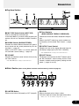
Owner’s Manual
FCC INFORMATION (U.S.A.)
1. IMPORTANT NOTICE: DO NOT MODIFY THIS
UNIT!
This product, when installed as indicated in the
instructions contained in this manual, meets
FCC requirements. Modifications not expressly
approved by Yamaha may void your authority,
granted by the FCC, to use the product.
not guarantee that interference will not occur in
all installations. If this product is found to be the
source of interference, which can be determined
by turning the unit “OFF” and “ON”, please try to
eliminate the problem by using one of the
following measures:
Relocate either this product or the device that is
being affected by the interference.
2. IMPORTANT: When connecting this product to
accessories and/or another product use only
high quality shielded cables. Cable/s supplied
with this product MUST be used. Follow all
installation instructions. Failure to follow instructions could void your FCC authorization to
use this product in the USA.
Utilize power outlets that are on different branch
(circuit breaker or fuse) circuits or install AC
line filter/s.
3. NOTE: This product has been tested and found
to comply with the requirements listed in FCC
Regulations, Part 15 for Class “B” digital devices. Compliance with these requirements
provides a reasonable level of assurance that
your use of this product in a residential environment will not result in harmful interference with
other electronic devices. This equipment generates/uses radio frequencies and, if not installed
and used according to the instructions found in
the users manual, may cause interference
harmful to the operation of other electronic
devices. Compliance with FCC regulations does
In the case of radio or TV interference, relocate/
reorient the antenna. If the antenna lead-in is
300 ohm ribbon lead, change the lead-in to coaxial type cable.
If these corrective measures do not produce
satisfactory results, please contact the local
retailer authorized to distribute this type of
product. If you can not locate the appropriate
retailer, please contact Yamaha Corporation of
America, Electronic Service Division, 6600
Orangethorpe Ave, Buena Park, CA90620
The above statements apply ONLY to those
products distributed by Yamaha Corporation of
America or its subsidiaries.
* This applies only to products distributed by YAMAHA CORPORATION OF AMERICA.
CANADA
This Class B digital apparatus complies with Canadian ICES-003.
Cet appareil numérique de la classe B est conforme à la norme NMB-003 du Canada.
• This applies only to products distributed by Yamaha Canada Music Ltd.
• Ceci ne s’applique qu’aux produits distribués par Yamaha Canada Musique Ltée.
NEDERLAND / NETHERLAND
The exclamation point within the
equilateral triangle is intended to
alert the user to the presence of
important operating and maintenance
(servicing) instructions in the
literature accompanying the product.
The lightning flash with arrowhead
symbol, within the equilateral
triangle, is intended to alert the user
to the presence of uninsulated
“dangerous voltage” within the
product’s enclosure that may be of
sufficient magnitude to constitute a
risk of electrical shock.
• Dit apparaat bevat een lithium batterij voor geheugen back-up.
• This apparatus contains a lithium battery for memory back-up.
• Raadpleeg uw leverancier over de verwijdering van de batterij op
het moment dat u het apparaat ann het einde van de levensduur
afdankt of de volgende Yamaha Service Afdeiing:
Yamaha Music Nederland Service Afdeiing
Kanaalweg 18-G, 3526 KL UTRECHT
Tel. 030-2828425
• For the removal of the battery at the moment of the disposal at
the end of the service life please consult your retailer or Yamaha
Service Center as follows:
Yamaha Music Nederland Service Center
Address
: Kanaalweg 18-G, 3526 KL UTRECHT
Tel
: 030-2828425
• Gooi de batterij niet weg, maar lever hem in als KCA.
• Do not throw away the battery. Instead, hand it in as small
chemical waste.
2
IMPORTANT SAFETY INSTRUCTIONS
INFORMATION RELATING TO PERSONAL INJURY, ELECTRICAL SHOCK,
AND FIRE HAZARD POSSIBILITIES HAS BEEN INCLUDED IN THIS LIST.
WARNING- When using any electrical or electronic product, basic precautions should always be followed. These precautions include, but are not limited to, the following:
1.
Read all Safety Instructions, Installation Instructions,
Special Message Section items, and any Assembly Instructions
found in this manual BEFORE making any connections, including connection to the main supply.
2.
Do not attempt to service this product beyond that
described in the user-maintenance instructions. All other servicing should be referred to qualified service personnel.
3.
Main Power Supply Verification: Yamaha products are
manufactured specifically for the supply voltage in the area
where they are to be sold. If you should move, or if any doubt
exists about the supply voltage in your area, please contact your
dealer for supply voltage verification and (if applicable) instructions. The required supply voltage is printed on the name plate.
For name plate location, please refer to the graphic found in the
Special Message Section of this manual.
4.
WARNING: Do not place this product or any other
objects on the power cord or place it in a position where anyone
could walk on, trip over, or roll anything over power or connecting cords of any kind. The use of an extension cord is not
recommended! If you must use an extension cord, the minimum
wire size for a 25' cord (or less) is 18 AWG. NOTE: The smaller
the AWG number, the larger the current handling capacity. For
longer extension cords, consult a local electrician.
5.
Ventilation: Electronic products, unless specifically
designed for enclosed installations, should be placed in locations
that do not interfere with proper ventilation. If instructions for
enclosed installations are not provided, it must be assumed that
unobstructed ventilation is required.
6.
Temperature considerations: Electronic products should
be installed in locations that do not seriously contribute to their
operating temperature. Placement of this product close to heat
sources such as; radiators, heat registers etc., should be avoided.
7.
This product was NOT designed for use in wet/damp
locations and should not be used near water or exposed to rain.
Examples of wet /damp locations are; near a swimming pool,
spa, tub, sink, or wet basement.
8.
This product should be used only with the components
supplied or; a cart ,rack, or stand that is recommended by the
manufacturer. If a cart, rack, or stand is used, please observe all
safety markings and instructions that accompany the accessory
product.
9.
The power supply cord (plug) should be disconnected
from the outlet when electronic products are to be left unused
for extended periods of time. Cords should also be disconnected
when there is a high probability of lightening and/or electrical
storm activity.
10.
Care should be taken that objects do not fall and liquids
are not spilled into the enclosure through any openings that may
exist.
11.
Electrical/electronic products should be serviced by a
qualified service person when:
a. The power supply cord has been damaged; or
b. Objects have fallen, been inserted, or liquids have been
spilled into the enclosure through openings; or
c. The product has been exposed to rain; or
d. The product does not operate, exhibits a marked change
in performance; or
e. The product has been dropped, or the enclosure of the
product has been damaged.
12.
This product, either alone or in combination with an
amplifier and headphones or speaker/s, may be capable of
producing sound levels that could cause permanent hearing loss.
DO NOT operate for a long period of time at a high volume
level or at a level that is uncomfortable. If you experience any
hearing loss or ringing in the ears, you should consult an audiologist.
IMPORTANT: The louder the sound, the shorter the time
period before damage occurs.
13.
Some Yamaha products may have benches and/or accessory mounting fixtures that are either supplied as a part of the
product or as optional accessories. Some of these items are
designed to be dealer assembled or installed. Please make sure
that benches are stable and any optional fixtures (where applicable) are well secured BEFORE using. Benches supplied by
Yamaha are designed for seating only. No other uses are recommended.
PLEASE KEEP THIS MANUAL
92-469-3
3
Owner’s Manual
Thank you for purchasing the YAMAHA AG-Stomp
Acoustic Guitar Pre-Amplifier.
Before you use the AG-Stomp, we urge you to take the
time and read this Owner’s Manual carefully in order to
get the most out of the device’s many functions and to obtain maximum life. Also, after reading the manual, please
keep it in a safe place for future reference.
Contents
Precautions .................................................. 5
External Control Settings .......................... 22
Nomenclature ............................................... 6
Tuner Mode ................................................. 23
■ Top Panel ......................................................... 6
■ Rear Panel ....................................................... 9
■ Enter the Tuner Mode ..................................... 23
■ Tuning ............................................................ 23
■ Setting the Standard Pitch ............................. 23
Connections ............................................... 10
■
■
■
■
■
■
Connecting the Power ....................................
Connecting a Mixer or Amplifier .....................
Connecting Headphones ...............................
Digital Output .................................................
Connecting an EXP Pedal ..............................
Connecting MIDI Devices ..............................
10
10
11
11
11
11
Using the AG-Stomp .................................. 12
■
■
■
■
■
■
Connecting the Guitar ....................................
Produce Sound ..............................................
Editing Settings ..............................................
Selecting Patches ..........................................
Storing Patches ..............................................
Other Convenient Functions ..........................
12
13
13
17
19
19
Effect Functions and Parameters ............. 21
4
Utility Mode ................................................. 24
■
■
■
■
■
■
About the Utility Mode ....................................
Footswitch Functions .....................................
MIDI Functions ...............................................
External Control Settings ...............................
EXP Pedal Settings ........................................
Feedback Reduction Operating Mode ...........
24
24
24
26
26
27
Error Messages .......................................... 28
Trouble Shooting ........................................ 28
Specifications ............................................. 29
MIDI Implementation Chart ....................... 30
Precautions
• Avoid using the AG-Stomp in the following locations to prevent possible damage:
• In direct sunlight or next to heating equipment.
• In extremely cold or hot locations.
• Locations exposed to high humidity or excessive dust.
• Locations subject to strong shocks or vibration.
• Before making any connections, make sure that the power is switched OFF on the AG-Stomp
and any external devices.
• To protect speakers from possible damage, always set the OUTPUT knob to “0” before switching
the power ON/OFF.
• When connecting a speaker to this unit, make sure that the power is switched OFF first.
• Do not apply excessive force to the switches, knobs and controls.
• The AG-Stomp is a precision device. Handle it with care and avoid dropping or jarring it.
• For safety, always remove the power adaptor from the AC wall outlet if there is any danger of
lightning striking in your area.
• Keep the AG-Stomp away from neon signs or fluorescent lighting to prevent noise pickup.
• To prevent damage and possibly electrical shock, never open the case and tamper with the
internal circuitry.
• Never use benzene, thinner or other volatile liquids for cleaning, as these chemicals may cause
damage or discoloration to the finish. Always use a dry, soft cloth to wipe off dust and dirt.
5
Nomenclature
■ Top Panel
Display & Main Section
Effect Section
Pre-Amplifier Section
Footswitch Section
● Display & Main Section
e MANUAL Button
e
r
t
q
w
y
Independent of the selected patch’s settings, this
button changes the tone to that produced by the
settings determined by the current position of each
of the knobs.
The button’s lamp will flash if the patch’s setting is
changed.
Press the [MANUAL] and [UTILITY] buttons simultaneously to enter the External Control Setting Mode.
(→ page 22)
q UP Button
w DOWN Button
r UTILITY Button
Press to change the Patch Number by +/-1. Hold
the button to change the Bank Number by +/-1. Simultaneously press the [UP] and [DOWN] buttons
to switch between the User ↔ Preset Areas.
Also, their flashing lamps are used to indicate the
relationship between the knob’s position and the
patch’s data value.
t STORE Button
Enters the Utility Mode. (→ page 24)
Press the [UTILITY] and [STORE] buttons simultaneously to enter the Tuner Mode. (→ page 23)
Enters the Store Mode. (→ page 19)
y Display
Displays patch numbers, values for parameter settings, etc.
6
Nomenclature
● Pre-Amp Section
!2
u
i
o
!0
!1
!0 Tone Controls
(BASS, MIDDLE, TREBLE, PRESENCE)
u MIC TYPE Select Switch (MIC TYPE)
Selects a microphone simulator type.
In the Utility Mode, it is used to select functions you
want to set such as Footswitch or MIDI Functions,
etc.
Controls the level of the knob’s related tone frequencies.
When in the SHIFT mode, they set the variable center frequency of the related Tone Control. (→ page
14)
i BLEND Control (BLEND/STEREO)
Controls the volume balance between the guitar’s
direct sound and the sound produced by the mic
simulator. (→ page 15)
When in the SHIFT mode, it is used to adjust the
mic simulator’s stereo setting. (→ page 15)
!1 OUTPUT Level Control
Controls the level of the signal delivered from the
AG-Stomp’s output jacks (OUTPUT, PHONES).
* The OUTPUT knob’s setting is not saved in memory.
o VOLUME
!2 SHIFT Button
Controls the absolute sound volume of that set by
the Tone Controls.
The button is used to enter the SHIFT mode in which
the Mic Simulator’s stereo setting and the Tone
Control’s variable center frequency settings can be
made. (→ page 14 and 15)
* The VOLUME knob’s setting is saved in memory.
● Effect Section (Refer to the [Effect Functions and Parameters] section on page 21)
!3
!4
!5
!6
!8
!7
!9
@0
@2
@1
@3
!3 LIMITER Button
!4 LEVEL
Switches the Limiter ON (lamp lit) or OFF (lamp off).
Adjusts the depth of the Limiter’s effect.
Turn to the right to increase the depth of the effect.
* When set to “0”, the Limiter will produce no effect.
7
Nomenclature
!5 Feedback Reduction Buttons
(FEEDBACK REDUCTION 1-5)
!9 SPEED/TIME Control
These switches are notch filters that are used to
eliminate feedback. The five notch filters can be used
to isolate and suppress those frequencies that are
causing the feedback.
The notch filter’s lamp will light when the corresponding band’s filter is active. Up to five notch filters can
be used simultaneously.
!6 Frequency Control (FREQ)
Sets the frequency of the selected Feedback
Reduction’s Notch Filter. (→ page 16)
!7 DEPTH Control
Sets the depth of the selected Feedback Reduction’s
Notch Filter. (→ page 16)
Chorus effect: Sets the speed of the Chorus.
Delay effect: Sets the Delay time.
@0 DEPTH/FEEDBACK Control
Chorus effect: Sets the depth of the Chorus effect.
Delay effect: Sets how long the delay will repeat.
@1 LEVEL
Chorus effect: Sets the volume level of the Chorus
effect.
Delay effect: Sets the volume level of the Delay effect.
@2 Reverb Effect Buttons
(HALL/ROOM/PLATE)
These buttons select the type of reverb effect to be
used. The currently selected effect’s lamp will light.
!8 CHORUS/DELAY Effect Buttons
These buttons select the Chorus and Delay effects.
The currently selected effect’s lamp will light.
@3 REVERB Volume
Sets the amount of Reverb that is added to the
guitar’s tone.
● Footswitch Section
@4
@4 Footswitches 1, 2, 3
Depending upon the settings in the Utility Mode (→
page 24), these switches can operate in the following manner:
• Select a patch (1/2/3) from the currently selected Bank.
• Switch the Effect Blocks ON/OFF (1: Limiter, 2: Chorus/Delay, 3: Reverb)
8
@5
@5 Bank Switch (AUTO F.R./BANK/TUNER)
• Press the switch when feedback occurs: The
AG-Stomp will automatically identify the problem frequency and apply a notch filter. (→ page
16)
• Hold the switch until the display flashes: Use
Footswitch 1 to change the Area, Footswitch 2
or 3 to select the Bank. (→ page 18)
• Hold the switch until “tu” appears in the display: Enters the Tuner Mode. (→ page 23)
Nomenclature
■ Rear Panel
@6
@7
@8
@9
#0
#1
#2
#3
#4
#6 #5
@6 Power Switch (STAND-BY ON/OFF)
#2 EXP. PEDAL Jack
This is the unit’s power switch.
Connect a foot controller (expression pedal) (optional) such as the YAMAHA FC-7 to this jack and
control individual parameter’s of the AG-Stomp. (→
page 22, 26)
* To protect the speakers, always set the OUTPUT knob !1
to “0” before switching the power ON/OFF.
@7 Power Adaptor Jack (AC IN 12V 1A)
Connect the supplied power adaptor to this jack.
* Never use a power adaptor other than the supplied adaptor.
Use of any other adaptor may result in damage, overheating,
fire, etc.
@8 Guitar Power Supply Switch
(+9V SUPPLY ON/OFF)
This switch allows the delivery of power (DC9V) to
an electric-acoustic guitar’s built-in pre-amplifier
through the AG-Stomp’s INPUT jack via the supplied TRS phone cable. (→ page 12)
@9 MIDI OUT Jack
This jack is used to transmit MIDI data from the AGStomp such as control changes, program changes,
data in the AG-Stomp’s memory, etc. (→ page 18)
#0 MIDI IN Jack
This jack is used to receive MIDI data from an external MIDI device such as a MIDI Foot Controller,
etc., which can be used select patches, control volume or control the AG-Stomp’s individual effects.
(→ page 18)
Also, AG-Stomp data saved in an external MIDI device can be returned to the AG-stomp via this jack.
(→ page 25)
#1 Digital Output Jack (DIGITAL OUT)
This jack is used to transmit the output of the AGStomp as digital data. Connect this jack to the digital input jack (COAXIAL) of a digital mixer, etc. (→
page 11)
#3 Headphone Jack (PHONES)
Connect a pair of headphones (optional) to this jack
to monitor the AG-Stomp’s sound when you want to
practice privately. (→ page 11)
* Even when headphones are connected to this jack, the
audio signal is delivered from the OUTPUT Jack #4 and
the DIGITAL OUT Jack #1.
#4 Output Jacks (OUTPUT R, L/MONO)
These are the AG-Stomp’s analog output jacks (TRS
balanced). Connect these jacks to the input jacks
on a power amp and speaker system, guitar amplifier, mixer, etc.
A commercially available PA type TRS phone cable
can be used to send a TRS balanced audio signal
from the AG-Stomp. Also, the supplied TRS-XLR
converter cables connected to these jacks deliver a
balanced audio signal to the XLR jacks on a mixer,
etc. (→ page 10)
* Use the L/MONO jack when connecting to a monaural device.
#5 INPUT Jack
#6 Input MUTE Switch
This is the AG-Stomp’s input jack. Connect a guitar
to this jack.
The supplied TRS phone cable can be used to deliver power to an electric-acoustic guitar’s built-in preamplifier from the AG-Stomp. (→ page 12)
When pressed, the Input MUTE Switch ( ) cuts
the signal from the INPUT jack to prevent noise,
etc. from entering the circuit. Use this switch when
connecting or disconnecting the guitar’s cable.
9
Connections
Before making any connections to any of the AG-Stomp’s INPUT and/or OUTPUT jacks,
make sure that the power on the AG-Stomp and all other devices is turned OFF to prevent
electrical shock or damage to the devices.
■ Connecting the Power
Use the supplied power adaptor (AC-10) to operate the AG-Stomp.
OFF (
)
1. Make sure the AG-Stomp’s Power Switch (STAND-BY) is in the OFF
position ( ).
2. Connect the power adaptor’s plug to the AC IN jack on the AG-Stomp.
3. Connect the power adaptor to an electric outlet.
Only use the supplied AC-10 power adaptor to power the unit.
The use of any other power adaptor may cause damage, overheating or fire, which can be very dangerous.
Make sure you use the proper AC voltage as indicated on the
power adaptor.
Never use the supplied power adaptor AC-10 with any other
device.
Electric
Outlet
Power Adaptor
AC-10
* The AC adaptor’s shape will vary
according to the country to which
the device is shipped.
■ Connecting a Mixer or Amplifier
1. Use the supplied TRS-XLR converter cable to convert the AG-Stomp’s outputs (balanced TRS) to balanced XLR outputs.
2. Use a commercially available PA type TRS phone cable, to connect the AG-Stomp’s output jack to the
balanced inputs of a mixer, power amplifier, etc.
3. When a monaural phone cable is used, connections will be unbalanced.
Mixer, Power Amplifier, etc.
To the AG-Stomp’s OUTPUT
L/MONO, R Jacks
TRS-XLR Converter
Cable (supplied)
XLR Cable
PA Type TRS Phone Cable
Monaural Phone Cable
Balanced XLR Output
1: Ground
2: Hot
3: Cold
Balanced TRS Output
T: Hot
R: Cold
S: Ground
Unbalanced Output
To realize the AG-Stomp’s full potential, we recommend using it in stereo.
10
Connections
■ Connecting Headphones
■ Connecting an EXP Pedal
Connect a pair of headphones to the AG-Stomp’s
PHONES jack (standard stereo) for monitoring the
AG-Stomp while practicing privately.
Use the OUTPUT knob to adjust the volume of the
headphones.
A foot controller (expression pedal) (optional), such
as the YAMAHA FC-7, etc., connected to the AGStomp’s EXP. PEDAL jack allows control of individual
parameters in the AG-Stomp. (→ page 22 and 26)
* Even when headphones are connected to this jack, the audio
signal is delivered from the OUTPUT Jack and DIGITAL OUT
Jack.
When using headphones, set the volume to
a comfortable level so as not to harm to your
hearing.
■ Digital Output
The AG-Stomp is equipped with a digital output jack
(COAXIAL, 44.1 kHz) that provides direct digital connection to the digital input jack on a digital mixer,
MD recorder, etc.
* The output level of the DIGITAL OUT jack cannot be controlled with the OUTPUT knob (the level is fixed).
■ Connecting MIDI Devices
The MIDI IN/OUT jacks allow for the exchange of
MIDI information between the AG-stomp and an
external MIDI device.
This allows data from the AG-Stomp to be stored
(using Bulk Dump) in a MIDI device such as the
YAMAHA MIDI Data Filer MDF3, etc. also, data
stored in an external MIDI device can be loaded into
the AG-Stomp.
Also, a MIDI foot controller, etc., can be used to select AG-Stomp patches, control individual parameters, or set individual effects. External MIDI devices
can also be controlled with the AG-Stomp. Refer to
the “Utility Mode” (→ page 24) for more information
on MIDI functions.
Digital Mixer, MD Recorder, etc.
11
Using the AG-Stomp
First, connect your guitar to the AG-Stomp and try to get some sound.
■ Connecting the Guitar
Before making any connections, make sure the AG-Stomp’s power is off, set the AG-Stomp’s OUTPUT
knob to “0” and the +9V SUPPLY switch to “OFF”. Then connect the INPUT jack on the rear panel to the
guitar’s output jack with any commercially available guitar cable (monaural ↔ monaural).
OFF (
)
Never connect the guitar to the AG-Stomp with the supplied TRS phone cable when the Guitar Power Supply
function described below is not used. If the TRS phone cable is used and the +9V SUPPLY switch is switched
“ON”, it may result in damage since a total of 18V will be supplied to the electric-acoustic guitar’s built-in preamplifier. Also, if the +9V SUPPLY switch is set to “OFF”, the electric-acoustic’s built-in pre-amplifier may function abnormally.
● Guitar Power Supply
Before supplying power to your guitar, make sure
that the guitar’s pre-amplifier battery has been replaced with the dummy battery supplied with the
AG-Stomp. Leaving the 006P 9V battery in place will
result in the guitar’s electronics receiving 18V of
power, causing damage.
[Setting]
1. Replace the electric/acoustic guitar’s built-in pre-amplifier battery with the dummy battery supplied with the
AG-Stomp.
The AG-Stomp is capable of supplying power to your electric-acoustic guitar’s built-in pre-amplifier via the supplied
TRS phone cable. Power is supplied to the electric-acoustic
guitar when the AG-Stomp’s power is switched ON.
This function is possible as long as your electric-acoustic
guitar meets the following conditions:
3. Use the supplied TRS phone cable to connect the AGStomp’s INPUT jack to the output jack on your electric/
acoustic guitar.
• The guitar uses a monaural output.
• The guitar uses a 006P 9V battery to supply power
to the guitar’s built-in pre-amplifier.
• The power to the guitar’s built-in pre-amplifier is
switched ON/OFF by connecting/disconnecting the
cable at the guitar’s jack.
• The guitar’s built-in electronics consume 10mA of
power, or less.
* Do not connect effectors, etc., between the AG-Stomp’s INPUT jack and the electric-acoustic guitar’s OUTPUT jack.
Power will not be supplied to the electric-acoustic guitar’s
built-in pre-amplifier if the AG-Stomp and the electric-acoustic
guitar are not directly connected.
Replace the electricacoustic guitar’s preamplifier battery with the
dummy battery.
Dummy Battery
(supplied)
2. Before making any connections, turn off the AG-Stomp’s
power and make sure its OUTPUT knob is set to “0”,
then set the +9V SUPPLY switch to “ON”.
* When the AG-Stomp’s power is ON, make sure that the MUTE
switch on the AG-Stomp is held down when connecting/disconnecting the cable.
Set the +9V SUPPLY
switch to the “ON”
position.
TRS Phone Cable (supplied)
12
If the AG-Stomp’s power
is ON, hold the MUTE
switch when making
connections.
Using the AG-Stomp
■ Produce Sound
■ Editing Settings
1. After confirming that the OUTPUT knob is set to
“0”, press the Power Switch (STAND-BY) ON
( ).
The panel knob and button functions can be used
to create your own original tone.
Switching the Power Switch ON when the OUTPUT
knob is turned up may result in damage to devices
such as the amplifier, speaker, headphones, etc.,
or cause unexpected accidents like damage to
your hearing due to high volume settings.
2. “U01” will appear in the display.
The characters (Memory Area: U (user), Bank
Number: 0, Patch Number:1) indicate the currently selected patch.
When a patch number is shown in the display,
this condition is known as the Play Mode. When
in the Play Mode, patches can be selected and
the knobs and buttons can be used to edit settings.
● Changing Pre-amp Settings
Since the AG-Stomp’s knob positions do not always
represent the tone that is currently being produced,
the knob must be “aligned” with the value set in
memory before changes can be made to that value.
For this reason, please follow the rules described
below when rotating the knobs.
• If the [UP] lamp flashes when a knob is rotated,
rotate the knob to the right (toward 10). If the
[DOWN] lamp flashes, rotate the knob to the left
(toward 0).
At this time, the patch’s data value (the value set
in the patch for the knob you are turning) will
flash in the display.
* As long as the value is flashing in the display, the display
and tone will not change even though the knob is being
rotated.
For now, try using this patch to produce some
sound.
3. Play a chord on the guitar and rotate the OUTPUT knob to the right to adjust the volume.
* If clipping due to the input signal overloading the AG-Stomp’s
circuit occurs, the BANK Switch Lamp will light.
If this is the case, reduce the volume on the guitar, or adjust
the AG-Stomp’s VOLUME, individual TONE control knobs
or individual Effect knobs. Also, if feedback occurs, please
refer to the “Feedback Reduction” section on page 16.
• Continue rotating the knob, when the knob
reaches the position corresponding to the patch’s
data value, the display as well as the [UP]/
[DOWN] lamps will stop flashing. After this, the
tone will change according to the knob’s position.
* After you stop moving the knob, the value will be displayed
for approximately two more seconds, then return to the normal display.
* Even if only one value is changed, the [MANUAL] lamp
will flash to indicate that data in the patch has been
changed.
Also, when all settings (except for the OUTPUT knob) are
changed, the [MANUAL] lamp will light.
• Once the knob is in an editable condition (in
which the patch data’s value can be changed),
rotating the knob will result in the value shown in
the display changing in regards to the knob’s
position causing a relative change in tone.
13
Using the AG-Stomp
The previously described rules apply to all knobs
except the OUTPUT knob.
The MIC TYPE SELECT switch also functions in
the same manner. When the knob is rotated, the
Mic Simulator type that is set in the patch data
will flash in the display. After rotating the knob
to the position of the Mic Simulator type indicated in the display, select the Mic Simulator type
you want to use.
The OUTPUT knob and VOLUME knob
Either knob can be used to change the volume however, the VOLUME knob setting is stored in the patch
data while the OUTPUT knob’s setting is not. Use
the VOLUME knob to set the volume of each patch
and use the OUTPUT knob to control the AGstomp’s output volume.
● Set the Tone Control’s Center Frequency
The BASS, MIDDLE, TREBLE and PRESENCE
tone controls each have a variable center frequency.
[Procedure]
1. Press the [SHIFT] button so that its lamp flashes
(enter the SHIFT mode).
2. To adjust the Center Frequency, rotate the Tone
Control of the related frequency range you want
to set. Turn the knob to the left (counter-clockwise) to lower the center frequency, or turn the
knob to the right (clockwise) to raise the center
frequency.
● Changing Effect Settings
Try switching each of the Effect Blocks ON/OFF or
try changing the effect. Also, try rotating knobs for
each of the effects to change the character of the
effect.
The AG-Stomp’s effects section is divided into the
following three blocks.
• Limiter (LIMITER)
• Chorus/Delay (CHORUS/DELAY)
• Reverb (HALL/ROOM/PLATE)
• Press the button of the effect you want to use to
select it (the lamp will light).
• In the Chorus/Delay and Reverb blocks, only one
effect per block can be used at a time.
Also, pressing a button that is lit will result in the
light going off and the effect in that block being
deactivated.
All knobs can be used to set or edit parameters
of the block’s selected effect.
* Refer to the “Effect Functions and Parameters” section on
page 21 for more information on the function and knob settings for individual effects.
* The operation of each of the effect’s knobs follows the same
rules as described in the pre-amp section.
14
Variable Range
• BASS ...............
• MIDDLE ...........
• TREBLE ...........
• PRESENCE .....
50Hz - 400Hz
200Hz - 1.6kHz
600Hz - 4.8kHz
2.0kHz - 16kHz
3. Press the [SHIFT] button so that its lamp turns
off (exit the SHIFT mode).
* If no editing is performed after 5 seconds of entering the
SHIFT mode, the mode will automatically be exited.
* A list of note names corresponding to each of the acoustic
guitar’s frets and their standard frequencies is provided in
the supplemental “Patch List”.
Please use the list when setting the Tone Control’s Variable
Center Frequency.
Tone Control Center Frequency settings are
stored in Patch Data.
Using the AG-Stomp
● Setting the Mic Simulator
The Mic Simulator is a specially designed circuit that adds to an electric/acoustic guitar, the special characteristics created when miking an acoustic guitar. It adds the airiness, which is found when a microphone is
placed in front of the guitar’s sound hole. The Mic Simulator is useful when your guitar is connected directly
to a mixer or recorder via a line, or when listened to through a pair of headphones for practice, etc.
The AG-Stomp provides the eight different Mic Simulator settings described below. The Mic Simulator creates a
stereo image by simulating two microphones positioned in front of the guitar but “aimed” at dif ferent angles
toward the guitar. Use the MIC TYPE Select Switch to try out some of the different microphone simulation types.
The BLEND knob is used to adjust the volume balance between the signal after it has passed through the Mic
Simulator (MIC tone) and the signal before it has passed through the Mic Simulator (DIRECT tone). Rotate the
knob fully to the left to hear only the DIRECT tone. Rotate the knob fully to the right to hear only the MIC tone.
Also, pressing the [SHIFT] button to enter the SHIFT mode (the SHIFT lamp flashes) lets you use the
BLEND (stereo) knob to adjust spaciousness of the sound produced by the Mic Simulator’s two microphones. Press the [SHIFT] button again to exit the SHIFT mode and the lamp will turn off.
* In the SHIFT mode, if a knob is not rotated after five seconds, the mode will be exited automatically.
Simulates microphones positioned
close to the guitar.
Microphone
Microphone
Microphone
Simulates microphones positioned
far from the guitar.
Microphone
Microphone
Microphone
Microphone
Microphone
MIC TYPE Select
Switch Position
Display
CONDENSER 1
C-1
Simulates the characteristics associated with a condenser mic
positioned close to the acoustic guitar.
CONDENSER 2
C-2
Simulates the characteristics associated with a condenser mic
positioned far from the acoustic guitar. Room sound is also present.
DYNAMIC 1
d-1
Simulates the characteristics associated with a dynamic mic
positioned close to the acoustic guitar.
DYNAMIC 2
d-2
Simulates the characteristics associated with a dynamic mic
positioned far from the acoustic guitar. Room sound is also present.
TUBE 1
t-1
Simulates the characteristics associated with a tube mic positioned
close to the acoustic guitar.
TUBE 2
t-2
Simulates the characteristics associated with a tube mic positioned
far from the acoustic guitar. Room sound is also present.
NYLON STR 1
n-1
Simulates the characteristics associated with a nylon string guitar
with a condenser mic positioned close to the guitar.
NYLON STR 2
n-2
Simulates the characteristics associated with a nylon string guitar with a
condenser mic positioned far from the guitar. Room sound is also present.
Description of the Simulation
* Mic Simulator settings are stored in patch data (MIC TYPE Select Switch Settings).
* When the Volume and Tone controls are set to high, the signal may clip inside of the AG-Stomp. In this case, decrease the guitar’s
volume, or adjust the AG-Stomp’s VOLUME, individual Tone Controls or individual Effect knobs. Also, if feedback occurs, please
use the Feedback Reduction Function described on page 16.
15
Using the AG-Stomp
● Feedback Reduction
The AG-Stomp is equipped with a Feedback Reduction Function to prevent feedback.
Feedback is caused when a certain frequency or
frequencies of the amplified sound causes the guitar to resonate thereby being re-amplified until a
steady howl or whistle is heard.
The AG-Stomp prevents feedback from occurring
by means of a notch filter, which is used to cut the
problem frequency. The AG-Stomp provides a total
of five notch filters (1-5) that can be applied and
operate simultaneously.
[Procedure]
The AG-Stomp provides two ways to set Feedback
Reduction.
• AUTO Setting
When feedback occurs, press the BANK switch.
The AG-Stomp will automatically identify the
problem frequency and apply an available notch
filter.
* The DEPTH is set to its maximum value (knob 10: -20dB)
in the AUTO setting.
* When feedback occurs with chords, etc., the AUTO setting
might not provide adequate performance. In this case, use
the MANUAL setting as described in the next section.
• MANUAL Setting
Press one of the [FEEDBACK REDUCTION]
buttons 1-5 (its lamp will flash). Use the FREQ
knob to select the frequency that needs to be
cut, then use the DEPTH knob to adjust the
amount of reduction needed.
Signal Level
Amount of reduction
Frequency
that needs
to be cut
Frequency
16
After adjustments have been made, press the
same button to set the setting (the lamp will light
and the filter will be active).
To deactivate (lamp OFF) an active filter (lamp
ON), press and hold the button of the filter you
want to deactivate until “OFF” appears in the
display.
* Refer to the “EFFECT FUNCTIONS and PARAMETERS”
section (page 21) for more information on settings for each
of the Feedback Reduction’s knobs.
If feedback is continuously occurring at a
high volume level, it may cause damage
to equipment. Please use caution.
Depending upon Utility Mode settings, Feedback Reduction settings are either included
with patch data (PrG) or, kept separate of
patch data so that the same Feedback Reduction settings/parameters will remain active (GLb) even though a different patch is
selected. (→ page 27)
Also, if the “GLb” (global) setting is used in
the Utility Mode, Feedback Reduction settings will be stored as global data when patch
data is stored so, the settings will be erased
if the power is turned off before the settings
are stored.
When another patch is selected, any settings that were changed will be returned
to their original condition. If you want to
keep the changes you made to those settings, use the Store Operation described
on page 19.
Using the AG-Stomp
■ Selecting Patches
The AG-Stomp holds a total of 60 patch programs
(patch) in its internal memory. The 60 patches are
divided into two areas, ten banks and three patches.
• AREA
There are two areas, the USER AREA and the
PRESET AREA. Data in the USER AREA (30
patches) can be freely rewritten using the
STORE operation. Data in the PRESET AREA
(30 patches) can be edited but the contents can
not be rewritten to PRESET AREA memory.
When a USER AREA patch is selected, a “U”
will appear in the display’s hundred’s digit (U01U93).
When a PRESET AREA patch is selected, a “P”
will appear in the display’s hundred’s digit (P01P93).
* When the AG-Stomp is shipped, both the PRESET AREA
and USER AREA contain the same patch data. (Refer to
the supplemental [Patch List]).
• BANK
The 30 patches in each area are divided into ten
banks (0-9).
● Use the [UP]/[DOWN] buttons on the
panel.
• Each time the [UP] button is pressed, the next
greater patch number is selected.
U01 → U02 → U03 → U11 → U12 →
U13.....U91 → U92 → U93 → P01 →
P02.....P93 → U01 (returns to the top)...
Each time the [DOWN] button is pressed, the
next lesser patch number is selected.
• Holding the [UP] button continuously increases
the bank number by one.
U01 → U11 → U21 → U31.....U91 →
P01 → P11.....P91 → U01 (returns to
the top)...
Holding the [DOWN] button continuously decreases the bank number by one.
• Simultaneously press the [UP] and [DOWN] button switches between the USER AREA and
PRESET AREA.
U01 ↔ P01
• PATCH
Each Bank contains three patches (1-3).
Try selecting some of the different patches and try
out some of the sounds.
To select a different patch, use one of the three
methods described below.
• Patch Characteristics
17
Using the AG-Stomp
● Using the Footswitches and Bank
Switch
• Press a Footswitch (1-3) to select the corresponding patch number 1-3 in the currently selected bank.
* If the Footswitch’s function is set to “EFF” in the Utility
Mode, it will not be possible to directly select a patch with
the Footswitch. (→ page 24)
• Press and hold the BANK switch until the display and the footswitch lamp flashes (Bank Select Mode), then remove your foot from the
switch. In this condition, the following procedure
can be used.
* Even when the Footswitch function is set to “EFF” in the
Utility Mode, stepping on the BANK switch will enter this
mode.
● Using a MIDI Controller
Patches in the AG-Stomp can also be selected by
transmitting MIDI Program Change data from an external MIDI device such as the YAMAHA MIDI Foot
Controller MFC10, etc.
1. Connect the MIDI IN jack on the AG-Stomp to
the MIDI OUT jack on an external MIDI device
with a MIDI cable.
* Make sure a standard MIDI cable is used. Also, the length
of the MIDI cable should be limited to 15 meters. The use
of a longer cable may result in trouble such as inferior performance of the device, etc.
MIDI IN
1. Press Footswitch 1 to switch between the USER
AREA (U) ↔ PRESET AREA (P). Changing to
another area will cause the Footswitch’s lamps
to flash.
MIDI
OUT
2. Each time Footswitch 2 is pressed, the Bank
Number will decrease by 1.
3. Each time Footswitch 3 is pressed, the Bank
Number will increase by 1.
4. [If the Footswitch Function is set to “PrG”]
Press the BANK switch to return to the Play
Mode. The patch number that was selected before performing step 1 of this procedure will be
selected.
[If the Footswitch Function is set to “EFF”]
Press the BANK switch and the patch number in
the display will flash. Footswitches 1-3 can be
used to select their corresponding patches (13).
Press the BANK switch to return to the PLAY
Mode with the Area/Bank/Patch you just selected
ready.
* To cancel the Area/Bank/Patch you just selected, press the
BANK switch. The AG-Stomp will return to its previous condition.
MFC10, etc
2. Match the AG-Stomp’s MIDI receive channel,
with the MIDI transmit channel on the external
MIDI device.
→ page 25 [Set the MIDI Receive Channel]
3. Create a Program Change Table*.
→ page 24 [Create a Program Change Table]
* This operation assigns patch numbers to corresponding
program change numbers that are received from an external device. For example, when the program change number “1” is received, the AG-Stomp’s patch number “U13”
is recalled.
* The default for Program Change Number: Patch Number
is
1: U01, 2: U02, ... 60: P93, 61: U01, ... 120: P93, ...128: U22.
4. When program change data is transmitted from
an external MIDI device and received by the AGStomp, the corresponding patch in the Program
Change Table you created will be selected.
* Refer to the Owner’s Manual of your external MIDI device, etc., for information on how to transmit program
change data.
18
Using the AG-Stomp
■ Storing Patches
■ Other Convenient Functions
After editing or creating an original patch, your settings can be stored in the USER AREA (U01-U93).
Try creating an original patch and store it.
Here are some other convenient functions that you
can use with the AG-Stomp.
● Storing Procedure
1. Press the [STORE] button.
When the Store Mode is entered, the display, the
STORE lamp and the Footswitch lamp that corresponds to the patch number will flash.
2. Select the patch (Bank and Patch Number) to
which you want to store the patch.
● Use Footswitches 1-3 to Switch the
Effects ON/OFF
Footswitch 1 can be used to act as an ON/OFF
switch for the Limiter, Footswitch 2 as an ON/OFF
switch for the Chorus/Delay Effect and Footswitch 3
as an ON/OFF switch for the Reverb Effect.
Limiter
Use the same procedure as described in “Selecting Patches” (page 17) to select the patch
number. You can also use the [UP]/[DOWN] buttons, Footswitches and BANK Switches to select the patch number. However, you cannot
change the AREA (data can only be written to
the USER AREA).
3. After selecting the patch number you want to
store your data in, hold the [STORE] button.
The store operation is complete when all the
lamps light.
* Utility mode settings are not stored in individual patches, they
are stored in the AG-Stomp’s memory as common settings for
all parameters.
* The OUTPUT knob’s setting is not stored in memory. Use the
Volume knob to set differences in volume for situations like
backing, soloing, etc.
* Data in the USER AREA (U01-U93) can be stored in an external MIDI device. (→ page 25)
* During the Store Operation, MIDI data can not be received.
The STORE operation is used not only to store your
original patches, but it can also be used to rearrange
your patches in an order suitable for use during live
performance.
Chorus/
Delay Effect
Reverb
Effect
1. Press the [UTILITY] button and set the MIC TYPE
Select Switch to CONDENSER 1.
After entering the Utility Mode, “F.S” will appear
in the display followed by the currently selected
Footswitch Function.
•
•
PrG : Select a patch
EFF : Switch the effect block ON/OFF
2. Use the [UP]/[DOWN] buttons to set the
Footswitch Function to “EFF”.
3. Press the [UTILITY] button to return to the Play
Mode.
4. Now, pressing Footswitches 1-3 will switch the
corresponding effect ON/OFF.
* To select a different Bank or Area, press and hold the BANK
switch until the display and the Footswitch Lamp flashes. (→
page 18)
19
Using the AG-Stomp
● Using the AG-Stomp Without Patches
● Chromatic Auto Tuner Function
The [MANUAL] button gives you direct control of the
AG-Stomp’s parameters and effects when patches
are not used.
Press the [MANUAL] button to enter the Manual
Mode (the lamp will light). In this mode, the tone
produced by the AG-Stomp is determined by the
current position of all knobs and effect buttons (with
the exception of the [FEEDBACK REDUCTION]
buttons), changes to any knob or button will have a
direct effect on the tone.
To enter the Tuner Mode, press the [UTILITY] and
[STORE] buttons simultaneously, or hold the BANK
switch until “tu” appears in the display when in the
Play Mode. The Tuner Mode supplies you with a
chromatic auto tuner for tuning.
To exit the Manual Mode, simply recall any patch.
Press a Footswitch (1-3) that corresponds to the
patch number shown in the display to return the AGStomp to the same condition previous to entering
the Manual Mode.
Also, the MANUAL Mode will be exited if the [SHIFT]
button is pressed to enter the SHIFT mode for editing one of the secondary parameters. At this time
the [MANUAL] button’s lamp will flash.
● Using a Foot Pedal (Controller)
A foot controller (expression pedal) (optional) such
as the YAMAHA FC-7, etc. connected to the EXP.
PEDAL jacks can be used to control of the AGStomp’s volume, tone or effect parameters (setting
values).
→ page 22 [External Control Settings]
● Control the AG-Stomp From an External MIDI Device
An external MIDI device’s MIDI OUT jack, connected
to the AG-Stomp’s MIDI IN jack via a MIDI cable
can be used to control the AG-Stomp’s volume, tone
or effect parameters (setting values).
→ page 22 [External Control Settings]
20
→ page 23 [Tuner Mode]
● Factory Default
To return the AG-Stomp’s settings to their factory
default condition, simultaneously hold the [UP] and
[MANUAL] buttons and turn the Power ON ( ), all
data in the USER AREA will be rewritten with data
for the patches listed in the “Patch List” which can
be found on a supplemental sheet.
When the AG-Stomp is reset to its factory
default condition, all patch data you stored
will be erased. We recommend that any
important data be stored in an external
MIDI device or that notes be taken of the
settings.
Effect Functions and Parameters
Limiter
● LIMITER
The Limiter prevents the input signal from exceeding a preset level (peak).
• LEVEL Knob
Rotate the knob to the right to increase the
amount of the Limiter’s effect.
When set to “0.0”, the Limiter will have no effect.
Feedback Reduction
The AG-Stomp provides a total of five Notch Filter
circuits that can be used to control specified frequencies.
Applied to frequencies that are the source of feedback, these Notch Filters are used to prevent feedback from occurring.
Press a band button (the lamp lights) and set the
parameter to operate the filter function.
A total of five Notch Filters can be applied at the
same time.
• FREQ Knob
Sets the frequency to be cut.
• DEPTH Knob
Sets how much the signal will be reduced.
* Refer to the Filter Graph found on page 16.
Chorus/Delay Effects
The AG-Stomp is equipped with Chorus and Delay
effects.
* Both the Chorus and Delay effects can not be used simultaneously. Use only one at a time.
● Chorus
This effect adds depth and width to the original tone
by modulating the pitch.
• SPEED Knob
Sets the speed at which the pitch will modulate.
• DEPTH Knob
Sets the depth at which the pitch will modulate.
• LEVEL Knob
Sets the amount of Chorus effect that is mixed
with the original tone.
● Delay
This digital delay effect repeats the original sound
after a determined pause.
• TIME Knob
Sets the delay time (the time separating the original sound and the repeated delay sound).
• FEEDBACK Knob
Sets number of times the delayed sound will repeat.
* Too high a setting may result in an uncontrolled oscillation
of sound. Please use caution.
• LEVEL Knob
Sets the amount of Delay effect that is mixed
with the original tone.
Reverb Effect
The AG-Stomp is equipped with three types of digital reverb, HALL, ROOM and PLATE.
● HALL (Hall Reverb)
This reverb effect simulates the reverb produced in
a concert hall.
• REVERB Knob
Controls the volume of the source signal into the
Reverb circuit.
● ROOM (Room Reverb)
This reverb effect simulates the natural reverb produced in a room.
• REVERB Knob
Controls the volume of the source signal into the
Reverb circuit.
● PLATE (Plate Reverb)
This reverb effect simulates the reverb produced by
a metal plate.
• REVERB Knob
Controls the volume of the source signal into the
Reverb circuit.
* If the same Reverb Type is switched from a patch using a
REVERB level other than “0” to a patch using a REVERB
level of “0”, the remaining reverb will be leftover. Of course,
the sound of the new patch will not be affected by the previous Reverb.
21
External Control Settings
A foot controller (expression pedal) (optional), such as the YAMAHA FC-7, connected to the
AG-Stomp’s EXP. PEDAL jack lets you control the volume and tone of the AG-Stomp and
effect parameters (setting values). These same parameters can also be controlled with MIDI
control changes.
* In the following section, the abbreviation [FR 1] button refers to the [FEEDBACK REDUCTION 1] button, etc.
■ Procedure
1. In the Play Mode, press the [MANUAL] and
[UTILITY] buttons simultaneously.
“CtL” will appear in the display when the External Control Setting Mode is entered.
2. Press the [LIMITER] button.
A control number will appear in the display.
Use the [UP]/[DOWN] buttons to set a control
number.
Up to 8 external control settings (control numbers: 1-8) can be stored in the AG-Stomp’s
memory. Eight individual controllers can be used
to control individual parameters or a single controller can be used to control 8 parameters.
3. Press the [FR 1] button.
The controller type will appear in the display.
Use the [UP]/[DOWN] buttons to set the type of
controller.
• EP
•
: The foot controller connected to the
AG-Stomp’s EXP. PEDAL jack is the
controller.
1-31, 64-95: Control change data received from an external MIDI device connected to the AG-Stomp’s
MIDI IN jack does the controlling.
Select the appropriate control
change number. (Refer to the
Owner’s Manual for the external
MIDI device for information on MIDI
control change numbers.)
4. Press the [FR 2] button
• A.Pr
• A.rE
• bAS
• mid
• trE
• PrE
• Lmt
• SPd
• dPt
• LE
• rE
: Post pre-amp volume
: Post reverb volume
: Tone Control (BASS)
: Tone Control (MIDDLE)
: Tone Control (TREBLE)
: Tone Control (PRESENCE)
: Limiter Level
: SPEED/TIME settings for the Chorus/Delay Effects
: DEPTH/FEEDBACK settings for the
Chorus/Delay Effects
: LEVEL setting for the Chorus/Delay Effects
: REVERB setting for the Reverb Effect
The controller that is set in step 3 of this procedure can control the above parameters (setting
values).
5. Press the [FR 3] button
The minimum parameter value (the controller’s
minimum parameter value) will appear in the display.
Use the [UP]/[DOWN] buttons to set the value
(0.0-10.0).
6. Press the [FR 4] button
The maximum parameter value (the controller’s
maximum parameter value) will appear in the display.
Use the [UP]/[DOWN] buttons to set the value
(0.0-10.0).
7. Press the [UTILITY] button to return to the Play
Mode.
The parameter type will appear in the display.
Use the [UP]/[DOWN] buttons to set the type of
parameter you want controlled.
• oFF : off (no control)
• bAL : Balance between the DIRECT tone
and the MIC tone (BLEND)
• StE : The stereo position of the two mics
(STEREO)
22
These external control settings are stored
with patch data.
Also, in the Utility Mode, there is a function
that is not related to patch data settings that
sets the Utility Mode’s External Control to
always ON (effective) or always OFF. (→ page
26)
Tuner Mode
This mode is used for tuning your guitar. In the Tuner Mode, the AG-Stomp operates like a
chromatic auto tuner.
■ Enter the Tuner Mode
To enter the Tuner Mode, use any one of the three
methods described below.
• In the Play Mode, press the [UTILITY] and
[STORE] buttons simultaneously.
• In the Play Mode, hold the BANK switch until
“tu” appears in the display. (The Tuner Mode
comes after the Bank Select Mode.)
• In the Bank Select Mode, hold the BANK switch
until “tu” appears in the display.
• If the pitch is low, the FEEDBACK REDUCTION
1 and 2 lamps will light while the FEEDBACK
REDUCTION 3 lamp flashes. If the pitch is high,
the FEEDBACK REDUCTION 4 and 5 lamps will
light while the FEEDBACK REDUCTION 3 lamp
flashes.
Finely tune the note until only the FEEDBACK
REDUCTION 3 lamp lights, then tuning is complete. (At this time the BANKS Switch’s lamp will
also light.)
Tuning is complete!
Raise
the pitch
Lower
the pitch
In the Tuner Mode, all outputs on the AGStomp (OUTPUT, PHONES, DIGITAL OUT) will
be muted (no sound will be produced.
Light Flash
3. Press the [UTILITY] button or the BANK Switch
to return to the Play Mode.
■ Tuning
The name of the note closest to that of which you
played will appear in the display, and the five lamps
will be used to indicate whether the note’s pitch is
high or low.
1. Use the [UP]/[DOWN] buttons to change the
standard pitch. (Refer to the following “Setting
the Standard Pitch” section.)
2. Play the note you want tune (play only a single
note).
• At first, roughly tune the guitar so that the name
of the note you want to tune appears in the display.
Note names are indicated in the display as follows:
A
Bb C
Flash Light
Db D
Eb E
F Gb G Ab
A bb C db d Eb E F Gb G Ab
■ Setting the Standard Pitch
Usually the tuner’s standard pitch is set to A=440Hz,
however there are some cases where the standard
pitch of an acoustic piano, etc. is set to a pitch other
than 440Hz.
The AG-Stomp’s standard pitch can be set to a pitch
anywhere between 436Hz and 444Hz.
1. In the Tuner Mode, press the [UP] or [DOWN]
button to display the standard pitch in the display.
* When the AG-Stomp’s power is switched ON, the standard
pitch is automatically set to 440Hz.
2. Every time the [UP] button is pressed, the standard pitch will increase by 1Hz, and every time
the [DOWN] button is pressed, the standard pitch
will decrease by 1Hz.
23
Utility Mode
The Utility Mode is used for the AG-Stomp’s overall system settings for things such as the
footswitch, MIDI, external controllers, EXP. PEDAL jack, etc.
* In the following section, the abbreviation [FR 1] button refers to the [FEEDBACK REDUCTION 1] button, etc.
■ About the Utility Mode
When in the Play Mode, press the [UTILITY] button
to enter the Utility Mode (the lamp lights).
When in the Utility Mode, press the [UTILITY] button to return to the Play Mode (the lamp turns off).
In the Utility Mode, MIDI messages cannot be
received. Use the Play Mode to receive MIDI
messages.
Also, individual Utility Mode settings are
saved when the Utility Mode is exited.
In the Utility Mode, it is possible to set the following
five functions. Use the MIC TYPE Select Switch to
select the function.
1: Footswitch Functions
2: MIDI Functions
3: External Control Settings
4: EXP Pedal Settings
5: Feedback Reduction Operating Mode
■ Footswitch Functions
Press the [UTILITY] button and set the MIC TYPE
Select Switch to CONDENSER 1 (“F.S” will appear
in the display).
● Select the Footswitch function.
Press the [LIMITER] button and use the [UP]/
[DOWN] buttons to set the function of Footswitches
(1-3).
• PrG : Use the Footswitches to select patches.
• EFF : Use the Footswitches to switch the effects ON/OFF.
Switch 1: Limiter
Switch 2: Chorus/Delay Effects
Switch 3: Reverb Effect
● Transmit Control Change Numbers
Sets the MIDI control change number that is transmitted when the Footswitch is switched ON/OFF.
(Available only when the Footswitch Function is set
to “EFF”.)
24
Press the [FR 1] button to display the value of the
currently selected setting in the display.
Press the Footswitch you want to set (the lamp
lights), and use the [UP]/[DOWN] buttons to set to
one of the following.
• oFF : MIDI data is not transmitted.
• 1-32, 64-95 : The Control Change Number
that is transmitted.
● Control Change Values transmitted when the
switch is OFF.
Sets the MIDI control change value that is transmitted when the Footswitch is switched OFF. (Available
only when the Footswitch Function is set to “EFF”.)
Press the [FR 2] button to display the value of the
currently selected setting in the display.
Press the Footswitch you want to set (the lamp
lights), and use the [UP]/[DOWN] buttons to set.
• 0-127 : The Control Change Value that is transmitted.
● Control Change Values transmitted when the
switch is ON.
Sets the MIDI control change value that is transmitted when the Footswitch is switched ON. (Available
only when the Footswitch Function is set to “EFF”.)
Press the [FR 3] button to display the value of the
currently selected setting in the display.
Press the Footswitch you want to set (the lamp
lights), and use the [UP]/[DOWN] buttons to set.
• 0-127 : The Control Change Value that is transmitted.
■ MIDI Functions
Press the [UTILITY] button and set the MIC TYPE
Select Switch to CONDENSER 2 (“mmd” will appear in the display).
● Create a MIDI Program Change Receive Table
Sets the corresponding patch that will be recalled
when a MIDI Program Change Number (referred to
as PRG No. from here on) is received.
Utility Mode
Press the [LIMITER] button to set the receiving MIDI
PRG No. Use the [UP]/[DOWN] buttons to select
the number.
• 1-128 : MIDI Program Change No.
Press the [FR 1] button to set the AG-Stomp’s patch
number. Just as in selecting a patch number in the
Play Mode, use the [UP]/[DOWN] buttons or the
Footswitches to select.
• U01-U93, P01-P93 :
The patch number that is recalled.
● Create a MIDI Program Change Transmit Table
When a Footswitch (1-3) is pressed to recall a patch,
a MIDI Program Change Number can be transmitted from the AG-Stomp’s MIDI OUT jack to control
an external effector, etc., from the AG-Stomp.
This table assigns to the patch, a MIDI PRG No.
that will be transmitted when the patch is recalled.
Press the [FR 2] button to set the AG-Stomp’s patch
number. Just as in selecting a patch number in the
Play Mode, use the [UP]/[DOWN] buttons or the
Footswitches to select.
• U01-U93, P01-P93 :
The patch number that is recalled.
● ON/OFF setting for MIDI Merge
Sets whether or not the MIDI signal that is received
via the AG-Stomp’s MIDI IN jack will also be transmitted via the MIDI OUT jack.
Press the [CHORUS] button and use the [UP]/
[DOWN] buttons to set the merge setting.
• on
• oFF
: Data is retransmitted via the MIDI OUT
jack.
: Data is not retransmitted via the MIDI
OUT jack.
* When the merge function is set to on, data retransmitted via
the MIDI OUT jack is not confined to the channel set in the
MIDI Receive Channel setting so all data from all channels
will be transmitted.
● MIDI Bulk Out
This operation transmits data stored in the AGStomp’s USER AREA as well as Utility Mode settings to an external device, such as the YAMAHA
MDF3, etc., which can be used to store MIDI data
for back up.
Use a MIDI cable to connect the AG-Stomp’s MIDI
OUT jack to the MIDI IN jack of an external MIDI
device.
Press the [FR 3] button to set the PRG. No. that will
be transmitted. Use the [UP]/[DOWN] buttons to set.
MIDI
IN
• 1-128 : MIDI Program Change No.
● Set the MIDI Receive Channel
Sets the AG-Stomp’s MIDI Receive Channel. The
MIDI channel set in this step is also used as the
device number for the bulk receive function.
MIDI
OUT
Press the [FR 4] button and use the [UP]/[DOWN]
buttons to set the MIDI receive channel.
• oFF : MIDI messages are not received
• ALL : MIDI messages from all channels are
received
• 1-16 : MIDI channel over which messages are
received.
● Set the MIDI Transmit Channel
Sets the AG-Stomp’s MIDI Transmit Channel. The
MIDI channel set in this step is also used as the
device number for the bulk out function.
Press the [FR 5] button and use the [UP]/[DOWN]
buttons to set the MIDI transmit channel.
• 1-16 : MIDI channel over which messages are
transmitted.
MDF3, etc.
To send all USER AREA data (U01-U93) and
Utility Settings with the Bulk Out Operation
Press the [DELAY] button (“ALL” will appear in the
display), then press the [STORE] button to carry out
the MIDI Bulk Out operation.
To send a single USER AREA patch (data) with
the Bulk Out operation
After pressing the [HALL] button, select the patch
number to Bulk Out. Just as in selecting a patch
number in the Play Mode, use the [UP]/[DOWN]
buttons or the Footswitches to select the patch. After selecting the patch, press the [STORE] button to
25
Utility Mode
carry out the MIDI Bulk Out operation with a single
patch.
* After transmitting the data, the device will return to its previous condition, ready to select another patch number.
● Set the External Control Number
Press the [FR 1] button and use the [UP]/[DOWN]
buttons to set a control number (1-8).
* Refer to the “External Control Settings” section (page 22).
● About the MIDI Bulk In Operation
This operation is used to return data stored in an
external MIDI device, such as the YAMAHA MDF3,
etc., to the AG-Stomp.
● Set the External Controller
Press the [FR 2] button and use the [UP]/[DOWN]
buttons to set the controller type (EP, 1-31, 6495).
Use a MIDI cable to connect the MIDI OUT jack on
the external MIDI device to the AG-Stomp’s MIDI IN
jack.
When the Bulk Out is carried out from the external
MIDI device, the AG-Stomp will receive the bulk data.
* Refer to the “External Control Settings” section (page 22).
* Use the AG-Stomp’s Play Mode to receive MIDI Bulk In data.
● Set the Parameter to be Controlled
Press the [FR 3] button and use the [UP]/[DOWN]
buttons to set the parameter to be controlled
( bAL-).
* Refer to the “External Control Settings” section (page 22).
When the MIDI Bulk In operation is carried
out, the contents of the patches in the USER
AREA will be rewritten.
Please make sure any important data is saved
before carrying out the MIDI Bulk In operation.
● Set the Parameter’s Minimum Value
Press the [FR 4] button and use the [UP]/[DOWN]
buttons to set the parameter’s minimum value (the
parameter’s value when the controller is set to its
minimum: 0.0-10.0).
* Refer to the “External Control Settings” section (page 22).
■ External Control Settings
Just as in the “External Control Settings” section on
page 22, these settings are used to control the AGStomp’s volume, tone and effect parameters from a
foot controller that is connected to the EXP. PEDAL
jack or from a MIDI device that is connected to the
MIDI IN jack.
Press the [UTILITY] button and set the MIC TYPE
Select Switch to DYNAMIC 1 (“CtL” will appear in
the display).
● External Control’s Operating Mode Setting
Press the [LIMITER] button and use the [UP]/
[DOWN] buttons to set the External Control’s Operating Mode.
• GLb : The external control setting in the Utility
Mode is always available.
• PrG : The external control setting that is set in
the patch is available.
• oFF : External control is always OFF.
The following five settings are only available when
the Operating Mode above is set to “GLb”.
● Set the Parameter’s Maximum Value
Press the [FR 5] button and use the [UP]/[DOWN]
buttons to set the parameter’s maximum value (the
parameter’s value when the controller is set to its
maximum: 0.0-10.0).
* Refer to the “[External Control Settings” section (page 22).
■ EXP. Pedal Settings
These settings are available when the EXP. Pedal
“EP” is selected as the controller in the External
Control Settings.
Press the [UTILITY] button and set the MIC TYPE
Select switch DYNAMIC 2 (“E.P” will appear in the
display).
● Set the Minimum Value of the EXP. Pedal
Sets the minimum value that indicates the position
of the EXP. Pedal.
Press the [LIMITER] button and use the [UP]/
[DOWN] buttons to set the position (0-128).
You can also hold the [LIMITER] button and move
the EXP. Pedal to set the position.
* Due to the relationship between the maximum and minimum
value, a value which results in a practical range (refer to the
illustration below) of less than 128 can not be used.
26
Utility Mode
● Set the Maximum Value of the EXP. Pedal
Sets the maximum value that indicates the position
of the EXP. Pedal.
Press the [FR 1] button and use the [UP]/[DOWN]
buttons to set the position (127-255).
You can also hold the [FR 1] button and move the
EXP. Pedal to set the position.
* Due to the relationship between the maximum and minimum
value, a value which results in a practical range of less than
128 can not be used.
* The value can not be set greater than that of the EXP. Pedal’s
Switch Setting.
Practical Effective
Range
Minimum
Value
Maximum
Adjustable
Range
Maximum
Value
● Transmitting Control Change Numbers from
the EXP. Pedal
Sets the MIDI control change number that is to be
transmitted when the EXP. pedal is used.
Press the [FR 2] button and use the [UP]/[DOWN]
buttons to set the control change number.
• oFF : MIDI is not transmitted
• 1-32, 64-95 :
The control change number that is to be
transmitted.
■ Feedback Reduction Operating
Mode
Press the [UTILITY] button and set the MIC TYPE
Select Switch to TUBE 1. After “F.r” appears in the
display, the current setting is displayed.
Use the [UP]/[DOWN] buttons to set the Feedback
Reduction Operating Mode.
• GLb : Even if the patch is changed, the same
Feedback Reduction parameters and
settings will remain active (the same as
the current condition).
• PrG : When patches are changed, the Feedback Reduction’s parameters and settings will be changed to those that are
stored with the patch’s data.
27
Error Messages
If an error occurs during operation, one of the following error message numbers will appear in
the display.
Stop operation of the AG-Stomp and follow one of the solutions described below.
E1: MIDI Receive Buffer Full
CAUSE:
Too much MIDI data is being received and the buffer is full
SOLUTION: Try reducing the amount of data being sent, or break the data into smaller blocks.
E2: Communication Error
CAUSE:
An abnormality is detected during MIDI communications.
SOLUTION: Check all connections, etc. and try again.
E3: Bulk Receive Check Sum Error
CAUSE:
The check sum does not match the received MIDI bulk dump data.
SOLUTION: Check all connections and transmitted data, and try again.
E4: Bulk Receive Data Abnormality
CAUSE:
An abnormality is detected while receiving the bulk dump.
SOLUTION: Check all connections and transmitted data, and try again.
Trouble Shooting
No Sound
→ Is the power adaptor properly connected?
→ Is the volume level on the guitar amplifier turned
up?
→ Is the VOLUME knob set to “0”?
→ Is the OUTPUT knob set to “0”?
→ If an EXP pedal is being used to control the
volume, try stepping on the pedal.
→ Is the Tuner Mode active? Press the [UTILITY]
button or press the BANK switch to return to
the Play Mode.
→ If power is being supplied to the electricacoustic guitar from the AG-Stomp.
• Is the +9V SUPPLY switch set to “ON”? (→
page 12).
• Is the electric-acoustic guitar’s pre-amplifier
battery replaced with the dummy battery? (→
page 12).
28
Rotating the Knobs Does Not Change
the Sound
→ Turn the knob until the value in the display
changes, then adjust the setting. (→ page 13)
→ Is that knob’s effect switched ON? After selecting the effect, by pressing the effect button, turn the knob to adjust the setting. (→ page
14)
Can Not Transmit MIDI
→ Is the MIDI channel matched with the MIDI
channel of the receiving device? (→ page 25)
→ Is the MIDI Merge set to “OFF”? (→ page 25)
Can Not Receive MIDI
→ Is the AG-Stomp in the Play Mode? Return to
the Play Mode and try receiving again.
→ Is the AG-Stomp’s MIDI receive channel set to
the same MIDI channel used by the transmitting device? (→ page 25)
Specifications
Digital Section
•
•
•
•
Full Digital Signal Processing
Mic Simulator: 8 Types
Feedback Reduction: 5-band
Digital Effects
• Limiter
• Digital Chorus, Digital Delay
• Hall Reverb, Room Reverb, Plate Reverb
• External Controller Function (EXP Pedal/MIDI): 8
Controllers/Parameters
• Tuner Function (Chromatic, Auto)
MIDI Functions
Receive: Program Change (Program Change Table
can be created), Control Change, Bulk In
Transmit: Program Change, Control Change, Bulk
Out, Merge Out
Connections
INPUT: Standard Stereo Phone Jack
OUTPUT L/MONO, R: Standard Stereo Phone Jack
(TRS Balanced)
PHONES: Standard Stereo Phone Jack
EXP. PEDAL: Standard Stereo Phone Jack
DIGITAL OUT: COAXIAL
MIDI IN, MIDI OUT: 5-pin DIN
A/D Converter
20 bit
D/A Converter
20 bit
Sampling Frequency
44.1kHz
Memory Allocations
Guitar Power Supply
9V power can be supplied via a TRS phone cable
to a guitar’s built-in pre-amplifier, etc. that consumes less than 10mA of power, and uses a monaural output.
Preset: 30
User: 30
Input Level/Impedance
(When using pre-amp bypass)
INPUT: -17 dBm / 1 MΩ
Controller/Switch
Top Panel
Push Switch x17
UP, DOWN, MANUAL, UTILITY, STORE, LIMITER, FEEDBACK REDUCTION 1-5, CHORUS, DELAY, HALL, ROOM, PLATE, SHIFT
Knob x15
MIC TYPE, BLEND, VOLUME, BASS,
MIDDLE, TREBLE, PRESENCE, LIMITER
LEVEL, FEEDBACK REDUCTION FREQ,
FEEDBACK REDUCTION DEPTH, CHORUS
SPEED/DELAY TIME, CHORUS DEPTH/DELAY FEEDBACK, CHORUS LEVEL/DELAY
LEVEL, REVERB LEVEL, OUTPUT
Footswitch x4
1, 2, 3, BANK
Rear Panel
STAND-BY ON/OFF, MUTE, +9V SUPPLY ON/
OFF
Display
7 Segment LED (3 digit) x1
Push Switch LED x17
Footswitch LED x4
Output Level/Impedance
OUTPUT L/MONO: Balance +4 dBm / 600 Ω
OUTPUT R: Balance +4 dBm / 600 Ω
PHONES: 0 dBm / 47 Ω
Power
Exclusive Power Adaptor (AC-10)
AC Output: AC 12 V, 1 A
Power Consumption
15 W
Dimensions
280(W)x70(H)x184(D)mm (11.0"x2.8"x7.2")
Weight
2.2 kg (4lbs. 4oz.)
Accessories
Power Adaptor (AC-10)
TRS Phone Cable for Guitar Power Supply (3m)
TRS-XLR Converter Cable (x2)
Dummy Battery
Owner’s Manual (this booklet)
* Specifications and design may change without
notice.
29
[ Acoustic Guitar Pre Amplifier ]
Date:1-May-2001
Model AG stomp MIDI Implementation Chart
Version : 1.0
+----------------------------------------------------------------------+
:
: Transmitted
:
Recognized
:
Remarks
:
:
Function ... :
:
:
:
:-------------------+----------------+----------------+----------------:
:Basic
Default
: 1 - 16
: 1 - 16, off
: memorized
:
:Channel Changed
: 1 - 16
: 1 - 16, off
:
:
:-------------------+----------------+----------------+----------------:
:
Default
: 1,3
: 1,3
: memorized
:
:Mode
Messages : x
: x
:
:
:
Altered
: ************** : x
:
:
:-------------------+----------------+----------------+----------------:
:Note
: x
: x
:
:
:Number : True voice: ************** : x
:
:
:-------------------+----------------+----------------+----------------:
:Velocity Note ON
: x
: x
:
:
:
Note OFF : x
: x
:
:
:-------------------+----------------+----------------+----------------:
:After
Key's
: x
: x
:
:
:Touch
Ch's
: x
: x
:
:
:-------------------+----------------+----------------+----------------:
:Pitch Bender
: x
: x
:
:
:-------------------+----------------+----------------+----------------:
:
0 : x
: x
:
:
:
1 - 31 : o
: o
:
:
:
32 - 63 : x
: x
:
:
:
64 - 95 : o
: o
:
:
: Control 95 -127 : x
: x
:
:
:
:
:
:
:
: Change
:
:
:
:
:
:
:
:
:
YAMAHA
MIDI Implementation Chart
30
:
:
:
:
:
:
:
:
:
:
:
:
:
:
:
:
:
:
:
:
:
:
:
:
:
:-------------------+----------------+----------------+----------------:
:Prog
: o 0 - 127
: o 0 - 127
:
:
:Change : True #
: ************** :
:
:
:-------------------+----------------+----------------+----------------:
:System Exclusive
: o
: o
: Bulk Dump
:
:-------------------+----------------+----------------+----------------:
:System : Song Pos. : x
: x
:
:
:
: Song Sel. : x
: x
:
:
:common : Tune
: x
: x
:
:
:-------------------+----------------+----------------+----------------:
:System
:Clock
: x
: x
:
:
:Real Time :Commands: x
: x
:
:
:-------------------+----------------+----------------+----------------:
:Aux :All Sound OFF: x
: x
:
:
:
:Reset All Cntrls : x
: x
:
:
:
:Local ON/OFF : x
: x
:
:
:
:All Notes OFF: x
: x
:
:
:Mes- :Active Sense : o
: x
:
:
:sages:Reset
: x
: x
:
:
:-------------------+----------------+----------------+----------------:
:
:
:
:
+-------------------+----------------+----------------+----------------+
Mode 1 : OMNI ON, POLY
Mode 2 : OMNI ON, MONO
o : Yes
Mode 3 : OMNI OFF, POLY
Mode 4 : OMNI OFF, MONO
x : No
MIDI Implementation Chart
31
V698590
Printed in Taiwan