1
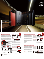
Mitsubishi iQ Platform
Programmable Controller
[QnU]
MELSEC-Q Series
The next level in Q performance
New products are
added to lineup!
[Low-capacity type]
Q00UJ/ Q00U/ Q01U
[Medium/High-capacity type]
Q10U/ Q20U
Unprecedented level of performance...
The next generation Q Series has arrived!
"Universal model: QnU" is the next
generation MELSEC-Q Series.
[High speed, high capacity]
In order to support the complex product equipment,
"Universal model: QnU" provides the fastest data
processing operation available on the market.
Furthermore, the machine control with the higher
speed and higher accuracy can be performed by
using the multiple CPU system.
The number of programs and memory capacity that
can be handled to process the large amount of
control/production management data are increased.
It is an ideal solution for users who want
to increase productivity and processing
speed of large-volume production
information, which is critical for
traceability.
It is the fastest basic operation
[Built-in Ethernet/USB port]
processing on the market* and can
The Ethernet connection is standardized for the top
layer of the information network.
The Ethernet port is built in the main body of
"Universal model: QnU". (Q03U and later)
The USB port is standardized for all models to
improve the usability.
greatly improve performance of systems.
Furthermore, the design concepts
inherited from the Q Series make it more
user-friendly and reliable.
This new generation programmable
[Enhanced lineup]
controller will bring your systems to the
next level
The low-capacity type models are added to the
lineup of the new generation programmable
controller, "Universal model: QnU".
Program capacity of 10 k to 260 k can be selected
for a specific purpose.
*As of October 2008
programmable
controller
Current production requirements
Such needs at production site
� Minimizing operation cycle
gave birth to this next generation
� Corresponding to strict quality management
� Adopting more complex, larger-scale equipment
programmable controller
Improved Productivity
More User - Friendly
� Supporting increasingly large volume control/production management data
� Responding to short product life cycle
� Improving equipment uptime
Easy Maintenance
� High-speed, high-accuracy machine control
Program example
By simultaneously processing a sequence program and multiple CPU
high-speed communication (operation cycle of 0.88 ms), high-speed
control is achieved. The multiple CPU high-speed communication cycle
is synchronized with motion control, cutting down unnecessary control.
Moreover, performance of motion control is two times faster than the
previous model, allowing high-speed, high-accuracy machine control.
Multiple CPU
high-speed communication
Q26UDEHCPU
Q06UDEHCPU
Programmable controller CPU
Motion CPU
Multiple CPU high speed
main base unit
Programmable controller CPU
Universal model
programmable controller
control processor
Device memory
Multiple CPU high-speed
communication memory
Multiple CPU
high-speed bus
Motion CPU
Device memory
Multiple CPU high-speed
communication memory
Programmable controller
I/O module
(Digital I/O)
Programmable controller
intelligent function module
Motion modules
Servo
amplifier
(Proximity dog signal,
manual pulse input)
(A/D, D/A, etc.)
Multiple CPU high-speed communication
compatible model:
Motion control
processor
SSCNET
Q Series programmable controller system bus
Q03U
Q04U
Q06U
Q13U
Q20U
Q26U
Q10U
Motor
3
High-speed
control with
multiple
CPUs
Motion CPU
Q06UDEHCPU
In-position Servo program start
signal
dedicated instruction
[K0: Real]
1 INC-1
Axis 1, 200PLS
Speed
10000 PLS/s
D(P).SVST
Measurement details
Motor speed
Time
In-position signal
In-position response time
〈In-position response time〉
In a 2-axis, multi-CPU system consisting of a programmable controller CPU and
motion CPU, the motion CPU receives the in-position signal from the amplifier of
the first axis. Next, the programmable controller CPU sends a start command to the
second amplifier. This example thus shows the time it takes from the stopping of
motion on one axis until the beginning of motion on a second axis. This time is a
good indicator of CPU-to-CPU data transfer speed.
Approx. 2 times faster
Acceleration of in-position signal response time
Universal model NEW
QnUD(E)HCPU+Q173DCPU
High Performance model QnHCPU+Q173HCPU
In-position signal response time
Long
Short
Approx. 3.5 times more
Multiple CPU shared memory capacity
Universal model NEW
The indicated CPU icons of compatible model include the Ethernet port type and RS-232 port type.
Example)
Programmable
controller CPU
QnUD(E)HCPU+Q173DCPU
14 k words
4 k words
High Performance model QnHCPU+Q173HCPU
Capacity [k words]
0
4
8
� Improved production time with ultra-high-speed processing
To correspond with increasing demands for shortening
production time of large-scale, complex systems, the new
model offers the fastest basic operation performance* on the
market: basic operation processing speed (LD) of 9.5 ns.
This means scan time is reduced, improving production time
and processing accuracy.
In addition, the programmable controller can realize
high-speed control which was previously supported by micro
computer boards only.
16
34 ns
High Performance model QnHCPU
Basic operation processing speed 0
(LD) [ns]
5
10
Universal model
(New model)
QnUD(E)HCPU: Q04/ 06/ 10/ 13/ 20/ 26UDHCPU,
Q04/ 06/ 10/ 13/ 20/ 26UDEHCPU
QnHCPU
: Q02/ 06/ 12/ 25HCPU
15
20
25
30
35
40
Approx. 5.8 times faster
Universal model NEW QnUD(E)HCPU
60 instructions/ms
10.3 instructions/ms
High Performance model QnHCPU
PC MIX value [instruction/ms]* 0
10
20
30
40
50
60
70
80
* The PC MIX value is the average number of instructions such as the
basic and data processing instructions executed in 1 ms. A larger
value indicates a higher processing speed.
� High-speed, high-precision real data processing
High Performance model
12
9.5 ns
Universal model NEW QnUD(E)HCPU
*As of October 2008
Floating point addition instruction processing speed is greatly
increased to 0.057 s to support high-speed, high-precision
operation processing of various production data.
Also, double precision operation is added to reduce
calculation errors when implementing complex equations.
Industry’s
fastest!
Approx. 3.5 times faster
Approx. 13.7 times faster
Universal model NEW QnUD(E)HCPU
0.057 ms
High Performance model QnHCPU
0.78 ms
Floating point addition (single precision) 0
instruction processing speed [ms]
Addition
(E+)
0.1
0.2
0.3
0.4
0.5
0.6
0.7
0.8
0.9
Universal model
QnUD(E)HCPU
High Performance model
QnHCPU
Single precision [ms]
0.057
0.78
Double precision [ms]
4.3 *1
87 *2
*1 Minimum value
*2 Indicates internal double precision operation processing speed
Q03U : Q03UDECPU, Q03UDCPU
4
Q03UDE/ Q04U/ Q06U/ Q10U/ Q13U/ Q20U/ Q26UDEHCPU
� Connect to various devices according to applications
High-speed communication with external devices is available via Ethernet. According to
application requirements, various devices can be connected.
Connection
with
various
devices
Command
Response
Simultaneous connection with multiple external
devices using a hub
Ethernet
Specific transmission of data to/from
upper-level servers and various
devices is applicable .
GX Developer
GOT1000
GT SoftGOT1000
MELSOFT connection communication
Measuring device,
vision sensor, etc.
User applications etc.
Various devices such
as temperature control
MC protocol communication
Upgraded Function
Socket communication
� Seamless communication across all layers
IP address setting is not required to connect GX Developer (programming tool) to the CPU module
directly (one-to-one connection). Also, the CPU module allows the use of either straight or cross
cable. Ethernet thus realizes easy communication with the CPU module like USB connection,
even operators who are not familiar with the network can easily connect it. (Patent pending)
Access
beyond
hierarchy
Ethernet
MELSECNET/H
Controller Network
Control level
network
� Easy to connect to programming tool via Ethernet
GX Developer
Seamless
communication
Enterprise level
network
7 modules
added to
lineup!
The QnU model supports the high-speed, high-capacity CC-Link IE Controller Network to allow
for massive data exchange. It can also communicate with MELSECNET/H, Ethernet, and
CC-Link seamlessly beyond the network type and hierarchy. Each programmable controller on
the network can be monitored/programmed by GX Developer connected via Ethernet.
GX Developer
Ethernet
Direct connection by a straight/cross cable
IP address setting not required!
Easy
connection,
no parameter
settings
� Search and display a list of connected CPUs
Using an Ethernet hub, GX Developer can be simultaneously connected to multiple CPUs.
The connected CPUs on the network can be searched and displayed in a list. By selecting a CPU
from the list, it is connected easily even if the IP address is unknown, and the operating status
can be checked.
List of CPUs found in a serach. Identify by the preset label and comment.
Sensor level
network
Device level
network
Check "Ethernet port direct connection."
� Always provide accurate clock data
With the SNTP* clock synchronization function, clock synchronization, which is a bottleneck
factor, is automatically performed. Accurate time of error occurrence can be grasped,
enabling the user to easily confirm the multiple CPU related error occurrence timing.
* SNTP: Simple Network Time Protocol
Clock data server
Ethernet
GX Developer
Easy
connection
from
the list
Error originated
in the Process 2.
Let's look into it!
Process 1 error logs
Process 2 error logs
Process 3 error logs
XXXX Error 13:15
XXXX Error 13:22
XXXX Error 13:07
XXXX Error 13:10
Current time13:40
5
Server error logs
Ethernet
Hub
Current time13:40
XXXX
XXXX
XXXX
XXXX
Error
Error
Error
Error
13:07
13:10
13:15
13:22
Process 2
Process 3
Process 1
Process 1
Precise
clock
synchronization
Easy to confirm how
the error spread.
Current time13:40
6
Program capacity (step)
Fastest
on the
market
Q26UDEH
260 k
� Enhanced lineup
7 new models are added to the 11 existing models.
Wide variety of modules are available to suit your needs of performance and functions.
・The USB port is standardized for all models and either Ethernet port type or
RS-232 port type can be selected.
Q26UDH
200 k
NEW
USB
Q20UDEH
Q20UDH
USB
RS-232
130 k
Ethernet
Q13UDEH
Memory card
NEW
USB
60 k
Q10UDEH
Q10UDH
Q04UDEH
Q03UDE
Point 1
Point 2
10 k
X coordinate
Y coordinate
Output value
USB
X coordinate
Operation error range
Point 2
Point n-1
Point 1
Y coordinate
NEW
Q00UJ
NEW
NEW
Point n
Point n
RS-232
120
Q01U
X coordinate
X
Input value
Y coordinate
Operation range
[Exponentiation instruction]
The exponentiation operation can be performed with the specified floating-point real number.
Example) Exponentiation operation on 32-bit floating-point real numbers D0, D1 and D10, D11
Q00U
80
SM402
60
� Improved performance
Compared to Basic model QCPU, the performance
is improved efficiently.
� Compatible with multiple programs
Compatible with up to 32 programs.
With the use of common instructions, programs can
be used for all Universal model modules. Thus the
program assets are easily utilized when changing
the CPU types.
40
9.5 Basic operation processing speed (ns)
20
[Operation]
Universal model NEW Q01UCPU
D0
20
40
60
80
X0
OFF
100
X0
2.7 instructions/ms
3
4
5
6
7
8
9
10
11
* The PC MIX value is the average number of instructions such as the basic and
data processing instructions executed in 1 μs. A larger value indicates a higher
processing speed.
Floating point addition (single precision) 0
instruction processing speed [ms]
49.5 ms
10
Category
Contact
instruction
Shift instruction
Data processing instruction
Special function instruction
0.24 ms
Q01CPU
20
30
40
50
ON
◎ Added instructions
String processing instruction
Approx. 206 times faster
Universal model NEW Q01UCPU
ON
OFF
140
120
9.8 instructions/ms
2
1 scan
ON
OFF
Approx. 3.6 times faster
1
D20
0.163
◎ Time chart
100 ns
Q01CPU
PC MIX value [instruction/ms]* 0
D21
0.22
X0
Universal model NEW Q01UCPU
Basic model
Exponentiation
D1
POW D0 D10 D20
60 ns
Q01CPU
Basic operation processing speed 0
(LD) [ns]
Basic model
X10
D10
1.2
Approx. 1.7 times faster
NEW
Basic model
D11
EMOV E1.2 D10
[Rising/falling pulse contact instruction of closed contact]
Previously, multiple instructions are required for the
rising/falling conditions of closed contact, but now, the
rising/falling pulse contact instruction of closed contact is
available for the efficient programming.
Low-capacity
type is
available
� Standardized USB port
Even when the RS-232 port
is occupied by a peripheral
such as a display device, the
programming tool can be
connected to the USB port.
Reduced
programming
work
Point 4
Q02U
Power supply and base unit
(5 slots) integrated type
Upgraded Function
Operation range
Point 3
EMOV E0.22 D0
Data control instruction
60
Clock instruction
Compatible model: Q00UJ
7
Q26U
Y
Coordinate points
Q03UD
15 k
Q20U
・CPUs from low capacity to high capacity can be selected according to your program size.
Setting item
20 k
Q13U
◎ Configuration of conversion data for scaling
Q04UDH
30 k
Q10U
[Scaling instruction]
The result of scaling for the conversion data (Point 1 to n in the figure below) with the specified
input value is stored to the specified device number as the output value.
Memory card
RS-232
Q06U
The convenient instructions such as the scaling instruction, exponentiation
instruction, and rising/falling pulse contact instruction of closed contact are added.
Programming that used to require complicated processes is now improved
efficiently and thus the programming work is reduced.
Q06UDH
USB
40 k
Q04U
� Easy programming with the convenient instructions
Q06UDEH
RS-232
Q03U
Memory card
Q13UDH
100 k
Compatible model:
Enhanced
lineup
Instruction
Symbol
Pulse operation start of closed contact
Pulse series connection of closed contact
Pulse parallel connection of closed contact
n-bit right/left shift of n-bit data
Average value calculation
String insertion
String deletion
Floating-point exponentiation operation
Floating-point common logarithm operation
Scaling (coordinate by point data)
Scaling (coordinate by X/Y data)
Date comparison
Time comparison
Q00U
Q01U
Q02U
Q03U
Q04U
Q06U
LDPI, LDFI
ANDPI, ANDFI
ORPI, ORFI
SFTBR, SFTBL
MEAN, DMEAN
STRINS
STRDEL
POW, POWD
LOG10, LOG10D
SCL, DSCL
SCL2, DSCL2
DT=, DT<>, DT>, DT<=, DT<, DT>=
TM=, TM<>, TM>, TM<=, TM<, TM>=
Q10U
Q13U
Q20U
Q26U
8
� Programs structured into individual routines
The number of programs is increased to 124 (max.) to allow detailed program management by
product, process, etc. This facilitates structuring programs into individual routines. Such
structured programs can be highly utilized and enhance visibility.
Also, standard ROM capacity is expanded to 4 MB (max.), enabling storage of label information of
function block (FB) and device comments of sequence programs in CPU.
Process O of product B
Program for product B
SM400
Process 2 of product B
SM400
Program for product A
SM400
M0
Process 1 of productY10B
SM400
Process 1 of productY10A
Y10
Program
memory
M0
SM400
Y11
INC D0
M1
M1
M0
M1
Y11
Y10
M1
M1
Y10
M0
M1
Y10
Y11
INC D10
Y11
INC D10
Y11
Y10
Max.
124
INC D10
Y11
INC D10
INC D10
Y11
INC D10
Y0
Q00UJ
Q00U
NEW
Program
capacity
Q01U
NEW
10 k steps
No. of programs
Standard ROM capacity
(Flash ROM)
SM400 M0
Common program
INC D10
CPU
M0
SM400
Process 2 of product A
Y0
M1
SM400 M0
Process O of product A
INC D0
SM400
Increased
program
capacity
NEW
Q03UDE
Q04UDEH Q06UDEH
Q02U
Q03UD
Q04UDH
Q06UDH
Q10UDEH
NEW
Q10UDH
NEW
Q13UDEH
Q13UDH
Q20UDEH
NEW
Q20UDH
NEW
Q26UDEH
Q26UDH
15 k steps 20 k steps 30 k steps 40 k steps 60 k steps 100 k steps 130 k steps 200 k steps 260 k steps
32
64
256 KB
124
512 KB
1 MB
2 MB
4 MB
� Easy to handle large-volume data
The capacity of standard RAM and memory card, which can be used as file register, is increased
to store larger amounts of production and quality data. With an 8 MB SRAM, a maximum of
4086 k words (about 4 times more than the previous model) can be used for file registers.
Furthermore, because the index register is extended to 32 bits, programming beyond 32 k words
is possible, enabling use of the entire area of file register for indexing. (Except Q00UJCPU)
To perform operation of structured (sequence) data efficiently, programming by indexing is
necessary. Index register processing speed is also dramatically improved, which can shorten
scan time when indexing is heavily used for sequence programs such as FOR to NEXT
instruction.
Previous model
ZR1
ZR0
High-speed,
large-volume
data
processing
ZR32767
Max. 32 k words for indexing
Extended to 32 bits
Universal model NEW
(with 8 MB SRAM card)
ZR0
ZR4184063
ZR1
Entire area of 4086 k words for indexing
◎Standard RAM capacity (file register capacity)
Q00UJ
Q00U
Q01U
NEW
NEW
NEW
Q03UDE
Q03UD
128 KB
(64 k words)
─
Q04UDEH
Q06UDEH
Q02U
Q04UDH
Q06UDH
192 KB
256 KB
768 KB
(96 k words)(128 k words)(384 k words)
Q10UDEH
NEW
Q13UDEH
Q10UDH
NEW
Q13UDH
1024 KB
(512 k words)
Q20UDEH
NEW
Q20UDH
NEW
Q26UDEH
Q26UDH
1280 KB
(640 k words)
◎Memory card (SRAM)
Model
Q2MEM-1MBS
Q2MEM-2MBS
Q3MEM-4MBS
Capacity
1 MB
2 MB
4 MB
Q3MEM-8MBS
8 MB
File register capacity*
505 k words
1017 k words
2039 k words
4086 k words
* Maximum capacity when the memory card is used as file register.
Memory card cannot be used for Q00UJ, Q00U, and Q01UCPU.
10
� Shortened startup time with sampling trace function
� Simplified program debugging task
The sampling trace function facilitates error analysis and program debugging timing
verification, reducing equipment error analysis time and startup time. For a multiple CPU
system, CPU-to-CPU data exchange timing can be also confirmed.
The collected data can be not only viewed on GX Developer but also exported to a CSV
file, allowing data analysis utilizing Excel.
The QnU model features the "Executional conditioned device test" function, which allows
the user to change the device value to the specified value at any step in the program.
Previously, a program for device setting must be added to debug a specific ladder block.
However, using this function, only the specified ladder block can be debugged without
modifying the program. This eliminates the program modification time for debugging and
simplifies the debugging task.
Intuitive setting in Wizard format
Upgraded Function
Analysis
with easy
settings
No program
modifications
required
Execute the device test by
setting the conditions such as
step No. and execution timing
(before/after executing
instruction).
The section to be debugged is
in a colored box for easy confirmation.
Set the total number of
traces and trigger position.
Select devices to be traced.
Compatible model: Q00UJ
Q00U
Q01U
Q02U
Q03U
Q04U
Q06U
Q10U
Q13U
Q20U
Q26U
All sections to be tested are displayed in a list. Reading the
registered conditions from the CPU and saving/reading the
execution condition file are available.
� Improved program creation with device extension
Upgraded Function
[Bit device extension]
The bit devices M and B can be extended up to 60 k points, improving
program readability. (Previously up to 32 k points)
Compatible model: Q00UJ
Q00U
Q01U
Q02U
Q03U
Q04U
Q06U
Q10U
Q13U
Q20U
Extended
bit/word
devices
Q26U
[Extended data registers/extended link registers]
The device range is extended by using the standard ROM or memory card as D device or
W device. (Previously used as file register (R/ZR))
Devices can be extended easily and flexibly for such case as word device increase by the
program change.
Trace result
Compatible model:
Q00U
Q01U
Q02U
Q03U
Q04U
Q06U
Q10U
Q13U
Q20U
Q26U
[Bit device extension]
The points can be set within the range from
0 k to 60 k points for the internal relay (M)
and link relay (B).
[Extended data registers/extended link registers]
For example, 640 k points of word device in
the standard ROM area can be divided as
follows according to the purpose of use for
Q26UDEHCPU.
Save the trace result in CSV file.
Data analysis using Excel is easy.
Compatible model:
11
Q00U
Q01U
Q02U
Q03U
Q04U
Q06U
Q10U
Q13U
Q20U
Q26U
・File register (R): 128 k points
・Extended data register (D): 256 k points
・Extended link register (W): 256 k points
12
� Secure data even after prolonged storage
Program and parameter files are automatically saved in the Flash ROM, which does not
require battery backup. This prevents data loss due to dead battery. This function
improves battery life. Important information such as device data is also protected in case
of dead battery. The data will be backed up in standard ROM, and the backup data
automatically returns when power is turned ON.
CPU built-in memory
Program memory
(Flash ROM)
No battery
backup
needed!
Program
cache memory
(SRAM)
Write programs
Program
protection
against
dead battery
For program
execution
Programming
tool
Device data
Backup
Latch data
Device memory execution
Backup
condition is
file
ON
(Standard ROM)
File register
(Standard RAM)
Compatible model: Q00UJ
Q00U
Q01U
Q02U
Q03U
Q04U
Q06U
� Shortened recovery time in system down
Q10U
Q13U
Q20U
Q26U
Upgraded Function
[CPU module exchange function using a memory card]
Backing up
All data in the CPU are backed up to a memory card with a simple operation.
data
By backing up data regularly, updated parameters and programs are always
stored to a memory card.
In a case of CPU failure, backed up data are restored from the memory card. Thus
the management of the backup data is not required and the recovery time from the
system down can be shortened.
CPU built-in memory
� Highly compatible with standard Q Series
[Compatibility with Q Series modules]
The standard Q Series modules can be used without modification. Common modules can
be used for the existing system and new system, lowering maintenance costs.
HMI
GOT1000 Series
MELSEC-Q Series
Q26UDEHCPU
Common
spare parts
Program memory
Device data (latch)
Standard ROM
Error history
Standard RAM
System data
Programming
tool
GOT
STEP 1 Install a memory card to the CPU and store the backup
data to the memory card in advance.
Common modules
[New model]
Multiple CPU
high speed
main base unit
Programmable
controller CPU
Q01UCPU
Q02UCPU
Q03UDEHCPU
STEP 2 When the CPU is failed, exchange it to the normal CPU
[Previous model]
Power supply
module
and install the memory card with the backup data.
Main base
unit
Programmable
controller CPU
Other Q Series
modules
Store backup data
to the memory card
STEP 3 Execute the backup data restoration function from the
programming tool, and reset the CPU to recover the data.
Q26UDEHCPU
Install the memory card and restore the data.
・Basic model
(3 models*)
・High Performance model
(5 models)
・Process CPU
(4 models)
・Universal model
(18 models*)
*Q00UJCPU/Q00JCPU is a power supply and 5-slot base unit integrated type CPU.
[Utilizing Q Series programs]
The existing QCPU programs can be utilized by changing the PLC type on GX Developer.
Switching of a module to Universal model CPU is performed smoothly.
CPUs can be switched easily
by changing the PLC type.
Q01CPU
Read from PLC
Q01CPU
13
Change PLC type
GX Developer
Compatible model:
Q02U
Q03U
Q04U
Q06U
Q10U
Q13U
Q20U
Q26U
� The serial number is indicated on the front of module
Without mounting off the module from the base unit, the serial number can be
checked on the front of the module.
The serial numbers can be also checked on the screen of GX Developer.
Easy
checking of
serial
numbers
Q01UCPU
Write to PLC
Q01UCPU
Serial number on the
front of module
Displayed on the Product Information
List screen of GX Developer
14
CPU Module Performance Specifications
Item
Q00UJCPU
Q00UCPU
Q01UCPU
NEW
NEW
NEW
Control method
Q02UCPU
Q03UDECPU
Q04UDEHCPU
Q06UDEHCPU
Q10UDEHCPU
Q03UDCPU
Q04UDHCPU
Q06UDHCPU
Q10UDHCPU
Sequence program control method
I/O control mode
Program language
(sequence control language)
USB (Note 6)
Peripheral
Ethernet
connection
(100BASE-TX/10BASE-T)
port
RS-232
Memory card interface
NEW
NEW
Q13UDEHCPU
Q20UDEHCPU
Q13UDHCPU
Q20UDHCPU
NEW
NEW
Refresh
Refresh
・Relay symbol language (ladder)
・Logic symbolic language (list)
・MELSAP3 (SFC), MELSAP-L
・Structured text (ST)
・Relay symbol language (ladder)
・Logic symbolic language (list)
・MELSAP3 (SFC), MELSAP-L
・Structured text (ST)
Yes
Yes
No
Q03UDECPU
Q04UDEHCPU
Q06UDEHCPU
Q10UDEHCPU
Q13UDEHCPU
Q20UDEHCPU
Q26UDEHCPU
Yes
Q03UDCPU
Q04UDHCPU
Q06UDHCPU
Q10UDHCPU
Q13UDHCPU
Q20UDHCPU
Q26UDHCPU
Yes
Yes
Processing LD instruction
speed
MOV instruction
(sequence
(Note 2)
instruction) PC MIX value (instruction/μs)
(Note 1)
Floating point addition
0.12 μs
0.08 μs
0.06 μs
0.04 μs
0.02 μs
0.0095 μs
0.0095 μs
0.24 μs
0.16 μs
0.12 μs
0.08 μs
0.04 μs
0.019 μs
0.019 μs
4.92
7.36
9.79
14
28
60
60
0.42 μs
0.30 μs
0.24 μs
0.18 μs
0.12 μs
0.057 μs
0.057 μs
Total number of instructions(Note 3)
822
848
850
858
858
Operation (floating point operation) instruction
Yes
Yes
Character string processing instruction
Yes
Yes
PID instruction
Yes
Yes
Special function instruction
(Trigonometric function, square
root, exponential operation, etc.)
Yes
Yes
0.5 to 2000 ms (setting available in units of 0.5 ms)
0.5 to 2000 ms (setting available in units of 0.5 ms)
Program capacity
10 k steps
15 k steps
Number of I/O device points [X/Y]
Number of I/O points [X/Y]
20 k steps
30 k steps
40 k steps
60 k steps
8192 points
256 points
1024 points
2048 points
100 k steps
130 k steps
4096 points
8192 points
Latch relay [L]
8192 points
8192 points
Link relay [B]
8192 points
8192 points
Timer [T]
2048 points
2048 points
0 points
0 points
1024 points
1024 points
Data register [D]
12288 points
12288 points
Link register [W]
8192 points
8192 points
Annunciator [F]
Edge relay [V]
Link special relay [SB]
Link special register [SW]
File register [R, ZR]
Step relay [S]
Index register/standard device register [Z]
Index register [Z]
(32-bit ZR indexing)
Pointer [P]
Interrupt pointer [I]
Special relay [SM]
Special register [SD]
Function input [FX]
Function output [FY]
Function register [FD]
Local device
Device initial values
2048
2048
2048
2048
(Note 4)
No
No
No
260 k steps
4096 points
8192 points
Counter [C]
200 k steps
8192 points
Internal relay [M]
Retentive timer [ST]
Q26UDHCPU
Sequence program control method
No
Constant scan (Function for
keeping regular scan time)
Q26UDEHCPU
points
points
points
points
65536 points
65536 points(Note 5) 98304 points(Note 5) 131072 points(Note 5)
8192 points
20 points
Max. 10 points (Z0 to Z18)
(Index register [Z] is used in double words.)
512 points
4096 points
128 points
256 points
2048 points
2048 points
16 points
16 points
5 points
Yes
Yes
393216 points(Note 5)
2048 points
2048 points
2048 points
2048 points
524288 points(Note 5)
655360 points(Note 5)
8192 points
20 points
Max. 10 points (Z0 to Z18)
(Index register [Z] is used in double words.)
4096 points
256 points
2048 points
2048 points
16 points
16 points
5 points
Yes
Yes
Note 1) The processing speed is the same even when the device is indexed.
Note 2) The PC MIX value is the average number of instructions such as the basic and data processing instructions executed in 1μs. A larger value indicates a higher
processing speed.
Note 3) Intelligent function module dedicated instructions are not included.
Note 4) Indicates the number of points in the default state. This can be changed with the parameter.
Note 5) Indicates the number of points when using the built-in memory (standard RAM). This can be expanded with the SRAM card or Flash card. (Writing from the program
is not possible with the Flash card.) Up to 4184064 points can be used with the SRAM card.
Note 6) The USB port terminal is mini-B.
15
16
General Specifications
Module Combinations for Multiple CPU System
General specifications indicate the environmental specifications in which this product can be installed and operated. Unless otherwise specified, the general specifications
apply to all products of the Q Series.
Install and operate the Q Series products in the environment indicated in the general specifications.
Item
Universal model
QCPU
Specifications
Operating ambient temperature
CPU 2 to 4
0 to 55℃
Storage ambient temperature
-25 to 75℃
(Note 3)
Operating ambient humidity
5 to 95%RH (Note 4), non-condensing
Storage ambient humidity
5 to 95%RH (Note 4), non-condensing
Frequency
Vibration resistance
Shock resistance
Operating atmosphere
Operating altitude (Note 5)
Installation location
【Multiple CPU high speed main base unit (Q3□DB)】
Conforms to
JIS B 3502,
IEC 61131-2
Under intermittent
vibration
Under continuous
vibration
Acceleration
Amplitude
3.5 mm (0.14 in.)
5 to 9 Hz
ー
9 to 150 Hz
9.8 m/s2
5 to 9 Hz
ー
9 to 150 Hz
4.9 m/s2
10 times each in
X, Y, Z directions
1.75 mm (0.069 in.)
(for 80 min.)
ー
Conforms to JIS B 3502, IEC 61131-2 (147 m/s , 3 times in each of 3 directions X, Y, Z)
2
No corrosive gases
2000 m (6562 ft.) or less
Inside control panel
Overvoltage category (Note 1)
Ⅱ or less
Pollution degree (Note 2)
2 or less
Equipment class
ClassⅠ
Note 1) This indicates the section of the power supply to which the equipment is assumed to be connected between the public electrical power distribution network and the
machinery within premises.
Category Ⅱ applies to equipment for which electrical power is supplied from fixed facilities.
The surge voltage withstand level for up to the rated voltage of 300 V is 2500 V.
Note 2) This index indicates the degree to which conductive material is generated in the environment where the equipment is used.
In pollution degree 2, only non-conductive pollution occurs. However, a temporary conductivity caused by condensation is to be expected.
Note 3) The storage ambient temperature is -20 to 75℃ if the system includes the AnS Series modules.
Note 4) The operating ambient humidity and storage ambient humidity are 10 to 90%RH if the system includes the AnS Series modules.
Note 5) Do not use or store the programmable controller under pressure higher than the atmospheric pressure of altitude 0 m.
Doing so can cause a malfunction.
When using the programmable controller under pressure, please consult your local Mitsubishi sales office or representative.
Q03UD
(E)
Q04UD
(E)
H
Q06UD
(E)
H
Q10UD
(E)
H
Q13UD
(E)
H
Q20UD
(E)
H
Q26UD
(E)
H
CPU 1
Sweep count
ー
Q00U
Q01U
Q02U
Q00U
Q01U
Q02U
Q03UD
(E)
Universal model
Q04UD
(E)
H
QCPU
Q06UD
(E)
H
Q10UD
(E)
H
Q13UD
(E)
H
Q20UD
(E)
H
Q26UD
(E)
H
Q02
(H)
High Performance model Q06H
QCPU
Q12H
Q25H
(Note 2)
◎ Possible
○ Possible (multiple CPU high-speed communication not available)
× Impossible
High Performance model
QCPU
Q02
(H)
Q06H
Q12H
Q25H
Process CPU
Q02PH
Q06PH
Q12PH
Q25PH
Motion CPU
Q172D
Q173D
Q172H
Q173H
Q172
Q173
PC CPU
×
×
×
×
×
×
1)
○(Note
(Note 3)
×
◎
○
○
◎
×
○(Note 3)
×
○
○
○
×
×
1)
○(Note
(Note 3)
High Performance model
QCPU
Process CPU
(Note 1)
【Main base unit other than Q3□DB】
Universal model
QCPU
CPU 2 to 4
Q00U
Q01U
Q02U
Q03UD
(E)
Q04UD
(E)
H
Q06UD
(E)
H
Q10UD
(E)
H
Q13UD
(E)
H
Q20UD
(E)
H
Q26UD
(E)
H
CPU 1
Q00U
Q01U
Q02U
Q03UD
(E)
Universal model
Q04UD
(E)
H
QCPU
Q06UD
(E)
H
Q10UD
(E)
H
Q13UD
(E)
H
Q20UD
(E)
H
Q26UD
(E)
H
Q02
(H)
High Performance model Q06H
QCPU
Q12H
Q25H
Note
Note
Note
Note
Note
Note
Note
1)
2)
3)
4)
5)
6)
7)
(Note 2)
Q02
(H)
Q06H
Q12H
Q25H
Q02PH
Q06PH
Q12PH
Q25PH
×
×
×
×
×
○
○
○
×
○
○
○
Motion CPU
Q172D
Q173D
(Note 7)
(Note 7)
Q172H
Q173H
Q172
Q173
PC CPU
(Note 1)
×
4)
○ (Note
(Note 6)
○(Note 3)
×
×
○(Note 3)
×
○ (Note 6)
(Note 6)
(Note 1)
(Note 6)
(Note 5)
(Note 1)
○(Note 3)
(Note 6)
For usable model name, version, etc., please contact your local Mitsubishi sales office or representative.
Q00U, Q01U, or Q02U does not support multiple CPU high-speed communication.
Only one PC CPU can be used.
Only one motion CPU can be used.
Cannot be used together with Q03UD(E), Q04UD(E)H, Q06UD(E)H, Q10UD(E)H, Q13UD(E)H, Q20UD(E)H, or Q26UD(E)HCPU.
The slim type main base unit (Q3□SB) and redundant power main base unit (Q38RB) cannot be used.
The slim type main base unit (Q3□SB) cannot be used.
【Comparison between built-in Ethernet port CPU and Ethernet module (QJ71E71-100)】
Function/performance
Communication speed
Built-in Ethernet port CPU
QnUDE(H)CPU
Ethernet module
QJ71E71-100
100 Mbps
100 Mbps
Communication with GX Developer
Yes
Yes
Communication with GOT
Yes
MC protocol communication
Yes
(Note 1)
Socket communication
No
(Note 2)
Random access buffer communication
No
Yes
Communication by data link instruction
No
Yes
FTP server function
Yes
Yes
E-mail function
No
Yes
Yes
Yes
(Fixed buffer communication)
Yes Note 1) QnA compatible 3E frame device memory access commands only. Refer to the manual for details.
Note 2) Some differences in function. Refer to the manual for details.
17
18
Ensuring an extensive global support network
meeting diverse support for today's needs
Product List
*Always refer to user's manuals for information on usable modules, restrictions, etc. before using.
*Contact your local Mitsubishi sales office or representative for the latest information on the MELSOFT versions and compatible OS.
CPU, base, power supply
Complying with international quality assurance standards
Product
All of Mitsubishi Electric's FA component products have acquired the international quality assurance "ISO9001" and
environment management system standard "ISO14001" certification. Mitsubishi's products also comply with various
safety standards, including UL standards, and shipping standards.
Q00UJCPU
Safety Standards
Council Directive of the
CE… European Communities
Underwriters Laboratories
UL… Listing
Shipping Standards
Lloyd's Register of
LR… Shipping approval
Norwegian Maritime
DNV… approval
Italian Maritime
RINA… approval
NK…ClassNK approval
American Bureau of
ABS… Shipping approval
Bureau Veritas
BV… approval
Model
Germanischer
GL… Lloyd approval
Outline
NEW
Q00UCPU
NEW
No. of I/O points: 1024 points, no. of I/O device points: 8192 points, program capacity: 10 k steps,
basic operation processing speed (LD instruction): 0.08 μs, program memory capacity: 40 KB,
peripheral connection ports: USB and RS232, no memory card I/F
Q01UCPU
NEW
No. of I/O points: 1024 points, no. of I/O device points: 8192 points, program capacity: 15 k steps,
basic operation processing speed (LD instruction): 0.06 μs, program memory capacity: 60 KB,
peripheral connection ports: USB and RS232, no memory card I/F
Q02UCPU
No. of I/O points: 2048 points, no. of I/O device points: 8192 points, program capacity: 20 k steps,
basic operation processing speed (LD instruction): 0.04 μs, program memory capacity: 80 KB,
peripheral connection ports: USB and RS232, with memory card I/F
Q03UDECPU
No. of I/O points: 4096 points, no. of I/O device points: 8192 points, program capacity: 30 k steps,
basic operation processing speed (LD instruction): 0.02 μs, program memory capacity: 120 KB,
multiple CPU high-speed communication, peripheral connection ports: USB and Ethernet, with memory card I/F
Q03UDCPU
No. of I/O points: 4096 points, no. of I/O device points: 8192 points, program capacity: 30 k steps,
basic operation processing speed (LD instruction): 0.02 μs, program memory capacity: 120 KB,
multiple CPU high-speed communication, peripheral connection ports: USB and RS232, with memory card I/F
Q04UDEHCPU
No. of I/O points: 4096 points, no. of I/O device points: 8192 points, program capacity: 40 k steps,
basic operation processing speed (LD instruction): 0.0095 μs, program memory capacity: 160 KB,
multiple CPU high-speed communication, peripheral connection ports: USB and Ethernet, with memory card I/F
Q04UDHCPU
No. of I/O points: 4096 points, no. of I/O device points: 8192 points, program capacity: 40 k steps,
basic operation processing speed (LD instruction): 0.0095 μs, program memory capacity: 160 KB,
multiple CPU high-speed communication, peripheral connection ports: USB and RS232, with memory card I/F
Q06UDEHCPU
No. of I/O points: 4096 points, no. of I/O device points: 8192 points, program capacity: 60 k steps,
basic operation processing speed (LD instruction): 0.0095 μs, program memory capacity: 240 KB,
multiple CPU high-speed communication, peripheral connection ports: USB and Ethernet, with memory card I/F
Q06UDHCPU
No. of I/O points: 4096 points, no. of I/O device points: 8192 points, program capacity: 60 k steps,
basic operation processing speed (LD instruction): 0.0095 μs, program memory capacity: 240 KB,
multiple CPU high-speed communication, peripheral connection ports: USB and RS232, with memory card I/F
CPU
Global FA Centers
"Mitsubishi Global FA Centers" are located throughout North America, Europe, and Asia to develop products complying
with international standards and to provide attentive services.
Q10UDEHCPU
◎North American FA Center
◎Korean FA Center
◎Guangzhou FA Center
Q10UDHCPU
MITSUBISHI ELECTRIC AUTOMATION, INC.
500 Corporate Woods Parkway, Vernon Hills, IL 60061, USA
Tel: +1-847-478-2100 / Fax: +1-847-478-0327
MITSUBISHI ELECTRIC AUTOMATION KOREA CO., LTD.
1480-6, Gayang-Dong, Gangseo-Ku, Seoul,
157-200, Korea
Tel: +82-2-3660-9607 / Fax: +82-2-3664-0475
MITSUBISHI ELECTRIC AUTOMATION (SHANGHAI) LTD.
GUANGZHOU OFFICE
Rm. 1609, North Tower, The Hub Center, No. 1068,
Xing Gang East Road, Haizhu District,
Guangzhou 510335, China
Tel: +86-20-8923-6713 / Fax: +86-20-8923-6715
Area covered: North America, Mexico, Chile, Brazil
Area covered: Korea
Area covered: China
Q13UDHCPU
No. of I/O points: 4096 points, no. of I/O device points: 8192 points, program capacity: 130 k steps,
basic operation processing speed (LD instruction): 0.0095 μs, program memory capacity: 520 KB,
multiple CPU high-speed communication, peripheral connection ports: USB and RS232, with memory card I/F
Q20UDEHCPU
MITSUBISHI ELECTRIC EUROPE B.V. GERMAN BRANCH
(Industrial Automation Division)
Gothaer Strasse 8, D-40880 Ratingen, Germany
Tel: +49-2102-486-0 / Fax: +49-2102-486-1120
MITSUBISHI ELECTRIC AUTOMATION (HONG KONG) LTD.
10/F, Manulife Tower, 169 Electric Road, North Point,
Hong Kong
Tel: +852-2887-8870 / Fax: +852-2887-7984
SETSUYO ENTERPRISE CO., LTD.
6F., No. 105 Wu-Kung 3rd RD, Wu-Ku Hsiang, Taipei Hsien,
248, Taiwan
Tel: +886-2-2299-2499 / Fax: +886-2-2299-2509
Q20UDHCPU
Area Covered: Europe
Area covered: China
Area covered: Taiwan
MITSUBISHI ELECTRIC EUROPE B.V. UK BRANCH
(Customer Technology Center)
Travellers Lane, Hartfield, Hertfordshire, AL10 8XB, UK
Tel: +44-1707-276100 / Fax: +44-1707-278992
MITSUBISHI ELECTRIC AUTOMATION (SHANGHAI) LTD.
MITSUBISHI ELECTRIC ASIA PTE, LTD.
307 Alexandra Road #05-01/02
Mitsubishi Electric Building, Singapore 159943
Tel: +65-6470-2480 / Fax: +65-6476-7439
Area covered: UK, Ireland
4/F Zhi Fu Plaza, No. 80 Xin Chang Road,
Shanghai 200003, China
Tel: +86-21-2322-2862 / Fax: +86-21-2322-2868
Area covered: China
Area covered: Southeast Asia, India
◎Central and Eastern Europe FA Center
◎Tianjin FA Center
◎Thailand FA Center
MITSUBISHI ELECTRIC EUROPE B.V. CZECH BRANCH
Avenir Business Park, Radlicka 714/113a,
15800 Praha 5, Czech Republic
Tel: +420-251-551-470 / Fax: +420-251-551-471
MITSUBISHI ELECTRIC AUTOMATION (SHANGHAI) LTD.
TIANJIN OFFICE
B-2-801/802, Youyi Building, No. 50 Youyi Road,
Hexi District, Tianjin 300061, China
Tel: +86-22-2813-1015 / Fax: +86-22-2813-1017
MITSUBISHI ELECTRIC AUTOMATION (THAILAND) CO., LTD.
Area covered: Czech Republic, Poland, Hungary, Slovakia
Area covered: China
◎Russian FA Center
◎Beijing FA Center
Mitsubishi Electric Europe B. V. - Representative Office
in St. Petersburg
Sverdlovskaya Emb., 44, Bld Sch, BC "Benua";
195027, St.Petersburg, Russia
Tel: +7-812-633-3496 / Fax: +7-812-633-3499
MITSUBISHI ELECTRIC AUTOMATION (SHANGHAI) LTD.
BEIJING OFFICE
9/F Office Tower 2, Henderson Center,
18 Jianguomennei Avenue, Dongcheng District,
Beijing 100005, China
Tel: +86-10-6518-8830 / Fax: +86-10-6518-8030
Area covered: Japan, England, Russia
Bang-Chan Industrial Estate No. 111, Soi Serithai 54,
T.Kannayao, A.Kannayao, Bangkok 10230, Thailand
Tel: +66-02-906-3238 / Fax: +66-02-906-3239
Area covered: Thailand
Battery
Memory card
No. of I/O points: 4096 points, no. of I/O device points: 8192 points, program capacity: 100 k steps,
basic operation processing speed (LD instruction): 0.0095 μs, program memory capacity: 400 KB,
multiple CPU high-speed communication, peripheral connection ports: USB and RS232, with memory card I/F
No. of I/O points: 4096 points, no. of I/O device points: 8192 points, program capacity: 130 k steps,
basic operation processing speed (LD instruction): 0.0095 μs, program memory capacity: 520 KB,
multiple CPU high-speed communication, peripheral connection ports: USB and Ethernet, with memory card I/F
◎Taiwan FA Center
◎ASEAN FA Center
No. of I/O points: 4096 points, no. of I/O device points: 8192 points, program capacity: 100 k steps,
basic operation processing speed (LD instruction): 0.0095 μs, program memory capacity: 400 KB,
multiple CPU high-speed communication, peripheral connection ports: USB and Ethernet, with memory card I/F
Q13UDEHCPU
◎Hong Kong FA Center
◎Shanghai FA Center
NEW
NEW
◎European FA Center
◎UK FA Center
No. of I/O points: 256 points, no. of I/O device points: 8192 points, program capacity: 10 k steps,
basic operation processing speed (LD instruction): 0.12 μs, program memory capacity: 40 KB,
peripheral connection ports: USB and RS232, no memory card I/F
NEW
NEW
No. of I/O points: 4096 points, no. of I/O device points: 8192 points, program capacity: 200 k steps,
basic operation processing speed (LD instruction): 0.0095 μs, program memory capacity: 800 KB,
multiple CPU high-speed communication, peripheral connection ports: USB and Ethernet, with memory card I/F
No. of I/O points: 4096 points, no. of I/O device points: 8192 points, program capacity: 200 k steps,
basic operation processing speed (LD instruction): 0.0095 μs, program memory capacity: 800 KB,
multiple CPU high-speed communication, peripheral connection ports: USB and RS232, with memory card I/F
Q26UDEHCPU
No. of I/O points: 4096 points, no. of I/O device points: 8192 points, program capacity: 260 k steps,
basic operation processing speed (LD instruction): 0.0095 μs, program memory capacity: 1040 KB,
multiple CPU high-speed communication, peripheral connection ports: USB and Ethernet, with memory card I/F
Q26UDHCPU
No. of I/O points: 4096 points, no. of I/O device points: 8192 points, program capacity: 260 k steps,
basic operation processing speed (LD instruction): 0.0095 μs, program memory capacity: 1040 KB,
multiple CPU high-speed communication, peripheral connection ports: USB and RS232, with memory card I/F
Q6BAT
Replacement battery
Q7BAT
Replacement large-capacity battery
Q7BAT-SET
Large-capacity battery with holder for mounting CPU
Q8BAT
Replacement large-capacity battery module
Q8BAT-SET
Large-capacity battery module with CPU connection cable
Q2MEM-1MBS
SRAM memory card, capacity: 1 MB
Q2MEM-2MBS
SRAM memory card, capacity: 2 MB
Q3MEM-4MBS
SRAM memory card, capacity: 4 MB
Q3MEM-4MBS-SET
SRAM memory card with cover, capacity: 4 MB
Q3MEM-8MBS
SRAM memory card, capacity: 8 MB
Q3MEM-8MBS-SET
SRAM memory card with cover, capacity: 8 MB
Q2MEM-2MBF
Linear Flash memory card, capacity: 2 MB
Q2MEM-4MBF
Linear Flash memory card, capacity: 4 MB
Q2MEM-8MBA
ATA card, capacity: 8 MB
Q2MEM-16MBA
ATA card, capacity: 16 MB
Q2MEM-32MBA
ATA card, capacity: 32 MB
Area covered: China
19
20
CPU, base, power supply
Product
I/O module
Model
Memory card adapter Q2MEM-ADP
Product
Model
QX10
Adapter for Q2MEM memory card's standard PCMCIA slot
AC
Replacement battery for Q2MEM-1MBS and Q2MEM-2MBS
Q3MEM-BAT
Replacement battery for Q3MEM-4MBS and Q3MEM-8MBS
QX28
Connection cable
QC30R2
RS-232 cable for connecting personal computer and CPU, 3 m (between mini-DIN6P and Dsub9P)
QX40
Cable disconnection
prevention holder
Q6HLD-R2
Holder for preventing RS-232 cable (programmable controller CPU connection) disconnection
QX40-TS
Q33B
3 slots, 1 power supply module required, for Q Series modules
Q35B
5 slots, 1 power supply module required, for Q Series modules
Q38B
8 slots, 1 power supply module required, for Q Series modules
Q312B
Main base
Multiple CPU high
speed main base
Slim type main base
Redundant power
main base
Extension base
Base
Redundant power
extension base
Extension cable
DIN rail mounting
adapter
Blank cover
Power supply
Slim type power supply
Redundant power supply
Power Supply with Life
Detection NEW
DC
(Positive
common) (Note 1)
Outline
16 points, 100 to 120 V AC, response time: 20 ms, 16 points/common, 18-point terminal block
QX10-TS
Q2MEM-BAT
SRAM card battery
CPU
Outline
NEW
16 points, 100 to 120 V AC, response time: 20 ms, 16 points/common, 18-point spring clamp terminal block
8 points, 100 to 240 V AC, response time: 20 ms, 8 points/common, 18-point terminal block
16 points, 24 V DC, response time: 1/5/10/20/70 ms, 16 points/common, positive common, 18-point terminal block
NEW
16 points, 24 V DC, response time: 1/5/10/20/70 ms, 16 points/common, positive common,
18-point spring clamp terminal block
QX40-S1
16 points, 24 V DC, response time: 0.1/0.2/0.4/0.6/1 ms, 16 points/common, positive common, 18-point terminal block
QX40H
16 points, 24 V DC, response time: 0/0.1/0.2/0.4/0.6/1 ms, 8 points/common, positive common, 18-point terminal block
NEW
QX41 (Note 2)
32 points, 24 V DC, response time: 1/5/10/20/70 ms, 32 points/common, positive common, 40-pin connector
12 slots, 1 power supply module required, for Q Series modules
QX41-S1 (Note 2)
32 points, 24 V DC, response time: 0.1/0.2/0.4/0.6/1 ms, 32 points/common, positive common, 40-pin connector
Q38DB
8 slots, 1 power supply module required, for Q Series modules
QX42 (Note 2)
64 points, 24 V DC, response time: 1/5/10/20/70 ms, 32 points/common, positive common, 40-pin connector
Q312DB
12 slots, 1 power supply module required, for Q Series modules
QX42-S1 (Note 2)
64 points, 24 V DC, response time: 0.1/0.2/0.4/0.6/1 ms, 32 points/common, positive common, 40-pin connector
Q32SB
2 slots, 1 slim type power supply module required, for Q Series modules
QX50
16 points, 48 V AC/DC, response time: 20 ms, 16 points/common, positive/negative common, 18-point terminal block
Q33SB
3 slots, 1 slim type power supply module required, for Q Series modules
Q35SB
5 slots, 1 slim type power supply module required, for Q Series modules
QX70
16 points, 5/12 V DC, response time: 1/5/10/20/70 ms, 16 points/common, positive/negative common,
18-point terminal block
Q38RB
8 slots, 2 redundant power supply modules required, for Q Series modules
Q63B
Input
AC/DC (Note 1)
DC sensor
QX70H
16 points, 5 V DC, response time: 0/0.1/0.2/0.4/0.6/1 ms, 8 points/common, positive common, 18-point terminal block
NEW
QX71
32 points, 5/12 V DC, response time: 1/5/10/20/70 ms, 32 points/common, positive/negative common, 40-pin connector
3 slots, 1 power supply module required, for Q Series modules
QX72
64 points, 5/12 V DC, response time: 1/5/10/20/70 ms, 32 points/common, positive/negative common, 40-pin connector
Q65B
5 slots, 1 power supply module required, for Q Series modules
QX80
Q68B
8 slots, 1 power supply module required, for Q Series modules
Q612B
12 slots, 1 power supply module required, for Q Series modules
Q52B
2 slots, power supply module not required, for Q Series modules
Q55B
5 slots, power supply module not required, for Q Series modules
Q68RB
8 slots, 2 redundant power supply modules required, for Q Series modules
QC05B
16 points, 24 V DC, response time: 1/5/10/20/70 ms, 16 points/common, negative common, 18-point terminal block
QX80-TS
DC
(Negative
common) (Note 1)
QX80H
NEW
16 points, 24 V DC, response time: 1/5/10/20/70 ms, 16 points/common, negative common,
18-point spring clamp terminal block
16 points, 24 V DC, response time: 0/0.1/0.2/0.4/0.6/1 ms, 8 points/common, negative common, 18-point terminal block
NEW
QX81 (Note 3)
32 points, 24 V DC, response time: 1/5/10/20/70 ms, 32 points/common, negative common, 37-pin D-sub connector
QX82 (Note 2)
64 points, 24 V DC, response time: 1/5/10/20/70 ms, 32 points/common, negative common, 40-pin connector
QX82-S1 (Note 2)
64 points, 24 V DC, response time: 0.1/0.2/0.4/0.6/1 ms, 32 points/common, negative common, 40-pin connector
0.45 m cable for connecting extension base unit
QX90H
16 points, 5 V DC, response time: 0/0.1/0.2/0.4/0.6/1 ms, 8 points/common, negative common, 18-point terminal block
QC06B
0.6 m cable for connecting extension base unit
QY10
QC12B
1.2 m cable for connecting extension base unit
QC30B
3 m cable for connecting extension base unit
QC50B
5 m cable for connecting extension base unit
QC100B
10 m cable for connecting extension base unit
Q6DIN1
DIN rail mounting adapter for Q38B, Q312B, Q68B, Q612B, Q38RB, Q68RB, Q65WRB, Q38DB, and Q312DB
Q6DIN2
DIN rail mounting adapter for Q35B, Q65B, and Q00UJCPU
Q6DIN3
DIN rail mounting adapter for Q32SB, Q33SB, Q35SB, Q33B, Q52B, Q55B, and Q63B
Q6DIN1A
DIN rail mounting adapter (with vibration-proofing bracket set) for Q3□B, Q5□B, Q6□B, Q38RB, Q68RB, and Q65WRB
QG60
Blank cover for I/O slot
Q61P
Input voltage: 100 to 240 V AC, output voltage: 5 V DC, output current: 6 A
Q62P
Input voltage: 100 to 240 V AC, output voltage: 5/24 V DC, output current: 3/0.6 A
Q63P
Input voltage: 24 V DC, output voltage: 5 V DC, output current: 6 A
Q64PN (Note 8)
Input voltage: 100 to 240 V AC, output voltage: 5 V DC, output current: 8.5 A
Q61SP
Input voltage: 100 to 240 V AC, output voltage: 5 V DC, output current: 2 A
Q63RP
Input voltage: 24 V DC, output voltage: 5 V DC, output current: 8.5 A
Q64RP
Input voltage: 100 to 120/200 to 240 V AC, output voltage: 5 V DC, output current: 8.5 A
Q61P-D
Input voltage: 100 to 240 V AC, output voltage: 5 V DC, output current: 6A
Relay
Triac
NEW
16 points, 24 V DC/240 V AC, 2 A/point, 8 A/common, response time: 12 ms, 16 points/common, 18-point terminal block
QY10-TS
NEW
QY18A
8 points, 24 V DC/240 V AC, 2 A/point, response time: 12 ms, 18-point terminal block, all points independent
QY22
16 points, 100 to 240 V AC, 0.6 A/point; 4.8 A/common, response time: 1 ms + 0.5 cycle, 16 points/common,
18-point terminal block, with surge suppressor
QY40P
16 points, 12 to 24 V DC, 0.1 A/point, 1.6 A/common, response time: 1 ms, 16 points/common, sink type,
18-point terminal block, with thermal and short-circuit protection and surge suppressor
QY40P-TS
Transistor
(Sink)
Output
Transistor
(Independent)
NEW
32 points, 12 to 24 V DC, 0.1 A/point, 2 A/common, response time: 1 ms, 32 points/common, sink type,
40-pin connector, with thermal and short-circuit protection and surge suppressor
QY42P (Note 2)
64 points, 12 to 24 V DC, 0.1 A/point, 2 A/common, response time: 1 ms, 32 points/common, sink type,
40-pin connector, with thermal and short-circuit protection and surge suppressor
QY50
16 points, 12 to 24 V DC, 0.5 A/point, 4 A/common, response time: 1 ms, 16 points/common, sink type,
18-point terminal block, with surge suppressor and fuse
QY68A
8 points, 5 to 24 V DC, 2 A/point, 8 A/module, response time: 10 ms, sink/source type,
18-point terminal block, with surge suppressor, all points independent
QY70
16 points, 5 to 12 V DC, 16 mA/point, 256 mA/common, response time: 0.5 ms, 16 points/common, sink type,
18-point terminal block, with fuse
QY71 (Note 2)
32 points, 5 to 12 V DC, 16 mA/point, 512 mA/common, response time: 0.5 ms, 32 points/common, sink type,
40-pin connector, with fuse
QY80
16 points, 12 to 24 V DC, 0.5 A/point, 4 A/common, response time: 1 ms, 16 points/common, source type,
18-point terminal block, with surge suppressor and fuse
QY80-TS
NEW
QH42P*
DC input/
transistor output
(Note 2)
QI60
Input: 32 points, 24 V DC, response time: 1/5/10/20/70 ms, 32 points/common, positive common;
output: 32 points, 12 to 24 V DC, 0.1 A/point, 2 A/common, response time: 1 ms, 32 points/common, sink type;
40-pin connector, with thermal and short-circuit protection and surge suppressor Input: 8 points, 24 V DC, response time: 1/5/10/20/70 ms, 8 points/common, positive common;
output: 7 points, 12 to 24 V DC, 0.5 A/point, 2 A/common, response time: 1 ms, 7 points/common, sink type;
18-point terminal block, with surge suppressor and fuse
QX48Y57
QX41Y41P*
Interrupt module
16 points, 12 to 24 V DC, 0.5 A/point, 4 A/common, response time: 1 ms, 16 points/common, source type,
18-point spring clamp terminal block, with surge suppressor and fuse
32 points, 12 to 24 V DC, 0.1 A/point, 2 A/common, response time: 1 ms, 32 points/common, source type,
37-pin D-sub connector, with thermal and short-circuit protection and surge suppressor
QY81P
I/O
16 points, 12 to 24 V DC, 0.1 A/point, 1.6 A/common, response time: 1 ms, 16 points/common, sink type,
18-point spring clamp terminal block, with thermal and short-circuit protection and surge suppressor
QY41P (Note 2)
TTL CMOS
Transistor
(Source)
16 points, 24 V DC/240 V AC, 2 A/point, 8 A/common, response time: 12 ms, 16 points/common,
18-point spring clamp terminal block
(Note 2)
Input: 32 points, 24 V DC, response time: 1/5/10/20/70 ms, 32 points/common, positive common;
output: 32 points, 12 to 24 V DC, 0.1 A/point, 2 A/common, response time: 1 ms, 32 points/common, sink type;
40-pin connector, with thermal and short-circuit protection and surge suppressor
16 points, 24 V DC, response time: 0.1/0.2/0.4/0.6/1 ms, 16 points/common, 18-point terminal block
*Number of occupied I/O points differs.
QH42P: 32 points
QX41Y41P: 64 points (32 points of first half: input, 32 points of latter half: output)
21
22
I/O module
Analog I/O module
Product
Connector
Spring clamp terminal block
Terminal block adapter
Connector/terminal block
conversion module
Cable
Relay terminal module
Cable
Model
Outline
A6CON1
32-point connector soldering type (40-pin connector)
A6CON2
32-point connector crimp-contact type (40-pin connector)
A6CON3
32-point connector pressure-displacement (flat cable) type (40-pin connector)
A6CON4
32-point connector soldering type (40-pin connector, cable connectable in bidirection)
A6CON1E
32-point connector soldering type (37-pin D-sub connector)
A6CON2E
32-point connector crimp-contact type (37-pin D-sub connector)
A6CON3E
32-point connector pressure-displacement (flat cable) type (37-pin D-sub connector)
Q6TE-18S
For 16-point I/O modules, 0.3 to 1.5 mm2 (22 to 16 AWG)
Q6TA32
For 32-point I/O modules, 0.5 mm2 (20 AWG)
Q6TA32-TOL
Q6TA32 dedicated tool
A6TBXY36
For positive common input modules and sink output modules (standard type)
A6TBXY54
For positive common input modules and sink output modules (2-wire type)
A6TBX70
For positive common input modules (3-wire type)
A6TBX36-E
For negative common input modules (standard type)
A6TBX54-E
For negative common input modules (2-wire type)
A6TBX70-E
For negative common input modules (3-wire type)
A6TBY36-E
For source output modules (standard type)
A6TBY54-E
For source output modules (2-wire type)
AC05TB
For A6TBXY36, A6TBXY54, and A6TBX70 (positive common/sink type); 0.5 m
AC10TB
For A6TBXY36, A6TBXY54, and A6TBX70 (positive common/sink type); 1 m
AC20TB
For A6TBXY36, A6TBXY54, and A6TBX70 (positive common/sink type); 2 m
AC30TB
For A6TBXY36, A6TBXY54, and A6TBX70 (positive common/sink type); 3 m
AC50TB
For A6TBXY36, A6TBXY54, and A6TBX70 (positive common/sink type); 5 m
AC80TB
For A6TBXY36, A6TBXY54, and A6TBX70 (positive common/sink type); 8 m *Common current 0.5 A or lower
AC100TB
For A6TBXY36, A6TBXY54, and A6TBX70 (positive common/sink type); 10 m *Common current 0.5 A or lower
AC05TB-E
For A6TBX36-E, A6TBY36-E, A6TBX54-E, A6TBY54-E, and A6TBX70-E (negative common/source type); 0.5 m
AC10TB-E
For A6TBX36-E, A6TBY36-E, A6TBX54-E, A6TBY54-E, and A6TBX70-E (negative common/source type); 1 m
AC20TB-E
For A6TBX36-E, A6TBY36-E, A6TBX54-E, A6TBY54-E, and A6TBX70-E (negative common/source type); 2 m
AC30TB-E
For A6TBX36-E, A6TBY36-E, A6TBX54-E, A6TBY54-E, and A6TBX70-E (negative common/source type); 3 m
AC50TB-E
For A6TBX36-E, A6TBY36-E, A6TBX54-E, A6TBY54-E, and A6TBX70-E (negative common/source type); 5 m
A6TE2-16SRN
For 40-pin connector 24 V DC transistor output modules (sink type)
AC06TE
For A6TE2-16SRN, 0.6 m
AC10TE
For A6TE2-16SRN, 1 m
AC30TE
For A6TE2-16SRN, 3 m
AC50TE
For A6TE2-16SRN, 5 m
AC100TE
For A6TE2-16SRN, 10 m
Product
Voltage input
Current input
Analog
input
Voltage/
current input
Model
Q68ADV
8 channels; input: -10 to 10 V DC; output (resolution): 0 to 4000, -4000 to 4000, 0 to 12000, -12000 to 12000,
0 to 16000, -16000 to 16000; conversion speed: 80 μs/channel; 18-point terminal block
Q62AD-DGH
2 channels; input: 4 to 20 mA DC; output (resolution): 0 to 32000, 0 to 64000; conversion speed: 10 ms/2 channels;
18-point terminal block; channel isolated; supplies power to 2-wire transmitter
Q66AD-DG (Note 5)
6 channels; input: 4 to 20 mA DC (when 2-wire transmitter is connected), 0 to 20 mA DC;
output (resolution): 0 to 4000, 0 to 12000; conversion speed: 10 ms/channel; 40-pin connector; channel isolated;
supplies power to 2-wire transmitter Q68ADI
8 channels; input: 0 to 20 mA DC; output (resolution): 0 to 4000, -4000 to 4000, 0 to 12000, -12000 to 12000,
0 to 16000, -16000 to 16000; conversion speed: 80 μs/channel; 18-point terminal block Q64AD
4 channels; input: -10 to 10 V DC, 0 to 20 mA DC; output (resolution): 0 to 4000, -4000 to 4000, 0 to 12000,
-12000 to 12000, 0 to 16000, -16000 to 16000; conversion speed: 80 μs/channel; 18-point terminal block
Q64AD-GH
4 channels; input: -10 to 10 V DC, 0 to 20 mA DC; output (resolution): 0 to 32000, -32000 to 32000, 0 to 64000,
-64000 to 64000; conversion speed: 10 ms/4 channels; 18-point terminal block, channel isolated
Q68AD-G (Note 5)
8 channels; input: -10 to 10 V DC, 0 to 20 mA DC; output (resolution): 0 to 4000, -4000 to 4000, 0 to 12000,
-12000 to 12000, 0 to 16000, -16000 to 16000; conversion speed: 10 ms/channel; 40-pin connector, channel isolated
Voltage output Q68DAVN
8 channels; input (resolution): 0 to 4000, -4000 to 4000, 0 to 12000, -12000 to 12000, -16000 to 16000;
output: -10 to 10 V DC; conversion speed: 80 μs/channel; 18-point terminal block,
transformer isolation between power supply and output
Current output
Q68DAIN
8 channels; input (resolution): 0 to 4000, -4000 to 4000, 0 to 12000, -12000 to 12000; output: 0 to 20 mA DC;
conversion speed: 80 μs/channel; 18-point terminal block, transformer isolation between power supply and output
Q62DAN
2 channels; input (resolution): 0 to 4000, -4000 to 4000, 0 to 12000, -12000 to 12000, -16000 to 16000;
output: -10 to 10 V DC, 0 to 20 mA DC; conversion speed: 80 μs/channel; 18-point terminal block,
transformer isolation between power supply and output
Q62DA-FG
2 channels; input (resolution): 0 to 12000, -12000 to 12000, -16000 to 16000;
output: -12 to 12 V DC, 0 to 22 mA DC; conversion speed: 10 ms/2 channels; 18-point terminal block;
channel isolated
Q64DAN
4 channels; input (resolution): 0 to 4000, -4000 to 4000, 0 to 12000, -12000 to 12000, -16000 to 16000;
output: -10 to 10 V DC, 0 to 20 mA DC; conversion speed: 80 μs/channel; 18-point terminal block;
transformer isolation between power supply and output
Q66DA-G (Note 5)
6 channels; input (resolution): 0 to 4000, -4000 to 4000, 0 to 12000, -12000 to 12000, -16000 to 16000;
output: -12 to 12 V DC, 0 to 22 mA DC; conversion speed: 6 ms/channel; 40-pin connector; channel isolated Q64RD
4 channels, platinum RTD (Pt100 [JIS C1604-1997, IEC 751 1983], JPt100 [JIS C1604-1981]),
conversion speed: 40 ms/channel, 18-point terminal block Q64RD-G
4 channels, RTD (Pt100 [JIS C1604-1997, IEC 751 1983], JPt100 [JIS C1604-1981], Ni100 Ω [DIN43760 1987]),
conversion speed: 40 ms/channel, 18-point terminal block, channel isolated
Q68RD3-G (Note 5)
8 channels, RTD (3-wire type, Pt100 [JIS C1604-1997, IEC 751 1983], JPt100 [JIS C1604-1981]),
Ni100 Ω [DIN43760 1987]), conversion speed: 320 ms/8 channels, 40-pin connector, channel isolated
Q64TD
4 channels, thermocouple (JIS C1602-1995), conversion speed: 40 ms/channel, 18-point terminal block
Q64TDV-GH
4 channels, thermocouple (JIS C1602-1995), micro voltage (-100 to 100 mV), conversion speed: sampling cycle x 3,
sampling cycle: 20 ms/channel, 18-point terminal block
Analog
output
Voltage/
current output
RTD
Temperature
input
Thermocouple
Q68TD-G-H01
8 channels, thermocouple (JIS C1602-1995, IEC 60584-1 [1995], IEC 60584-2 [1982]),
conversion speed: 320 ms/8 channels, 40-pin connector
(Note 5) (Note 7)
Q68TD-G-H02
(Note 5)
Temperature
control
8 channels, thermocouple (JIS C1602-1995, IEC 60584-1 [1995], IEC 60584-2 [1982]),
conversion speed: 640 ms/8 channels, 40-pin connector
4 channels, platimum RTD (Pt100, JPt100), no heater disconnection detection, sampling cycle: 0.5 s/4 channels,
18-point terminal block
Q64TCRTBW
4 channels, platimum RTD (Pt100, JPt100), with heater disconnection detection, sampling cycle: 0.5 s/4 channels,
two 18-point terminal blocks
Q64TCTT
4 channels, thermocouple (K, J, T, B, S, E, R, N, U, L, PLII, W5Re/W26Re), no heater disconnection detection,
sampling cycle: 0.5 s/4 channels, 18-point terminal block Q64TCTTBW
4 channels, thermocouple (K, J, T, B, S, E, R, N, U, L, PLII, W5Re/W26Re), with heater disconnection detection,
sampling cycle: 0.5 s/4 channels, two 18-point terminal blocks Q62HLC
2 channels, input: thermocouple/micro voltage/voltage/current, conversion speed (input): 25 ms/2 channels,
sampling cycle: 25 ms/2 channels; output: 4 to 20 mA DC, conversion speed (output): 25 ms/2 channels;
18-point terminal block, with 5 PID control modes
Thermocouple
Loop control
NEW
Q64TCRT
Platinum RTD
23
Outline
24
Pulse I/O and positioning module
Product
Channel isolated pulse input
High-speed counter
Open collector
output
(Note 4)
Differential output
(Note 4)
Positioning
With SSCNET
connectivity
Information module
Model
QD60P8-G
8 channels, 30 kpps/10 kpps/1 kpps/100 pps/50 pps/10 pps/1 pps/0.1 pps, count input signal: 5/12 to 24 V DC
QD62
2 channels; 200/100/10 kpps; count input signal: 5/12/24 V DC; external input: 5/12/24 V DC;
coincidence output: transistor (sink), 12/24 V DC, 0.5 A/point, 2 A/common; 40-pin connector
(Note 2)
QD62D
2 channels; 500/200/100/10 kpps; count input signal: EIA standards RS-422-A (differential line driver),
external input: 5/12/24 V DC; coincidence output: transistor (sink), 12/24 V DC, 0.5 A/point, 2 A/common;
40-pin connector
(Note 2)
QD62E (Note 2)
2 channels; 200/100/10 kpps; count input signal: 5/12/24 V DC; external input: 5/12/24 V DC;
coincidence output: transistor (source), 12/24 V DC, 0.1 A/point, 0.4 A/common; 40-pin connector
QD63P6 (Note 4)
6 channels, 200/100/10 kpps, count input signal: 5 V DC, 40-pin connector
QD75P1
1 axis; control unit: mm, inch, degree, pulse; no. of positioning data: 600/axis; max. output pulse: 200 kpps;
40-pin connector
QD75P2
2 axes; 2-axis linear interpolation, 2-axis circular interpolation; control unit: mm, inch, degree, pulse;
no. of positioning data: 600/axis; max. output pulse: 200 kpps; 40-pin connector
QD75P4
4 axes; 2-/3-/4-axis linear interpolation, 2-axis circular interpolation; control unit: mm, inch, degree, pulse;
no. of positioning data: 600/axis; max. output pulse: 200 kpps; 40-pin connector
QD70P4
4 axes, control unit: pulse, no. of positioning data: 10/axis, max. output pulse: 200 kpps, 40-pin connector
QD70P8
8 axes, control unit: pulse, no. of positioning data: 10/axis, max. output pulse: 200 kpps, 40-pin connector
QD75D1
1 axis; control unit: mm, inch, degree, pulse; no. of positioning data: 600/axis; max. output pulse: 1 Mpps;
40-pin connector
QD75D2
2 axes; 2-axis linear interpolation, 2-axis circular interpolation; control unit: mm, inch, degree, pulse;
no. of positioning data: 600/axis; max. output pulse: 1 Mpps; 40-pin connector
QD75D4
4 axes; 2-/3-/4-axis linear interpolation, 2-axis circular interpolation; control unit: mm, inch, degree, pulse;
no. of positioning data: 600/axis; max. output pulse: 1 Mpps; 40-pin connector
QD70D4
4 axes, control unit: pulse, no. of positioning data: 10/axis, max. output pulse: 4 Mpps, 40-pin connector
QD70D8
8 axes, control unit: pulse, no. of positioning data: 10/axis, max. output pulse: 4 Mpps, 40-pin connector
QD75M1
1 axis; control unit: mm, inch, degree, pulse; no. of positioning data: 600/axis; 40-pin connector
QD75M2
2 axes; 2-axis linear interpolation, 2-axis circular interpolation; control unit: mm, inch, degree, pulse;
no. of positioning data: 600/axis; 40-pin connector
QD75M4
4 axes; 2-/3-/4-axis linear interpolation, 2-axis circular interpolation; control unit: mm, inch, degree, pulse;
no. of positioning data: 600/axis; 40-pin connector
QD75MH1
1 axis; control unit: mm, inch, degree, pulse;
no. of positioning data: 600/axis; 40-pin connector; with SSCNET III connectivity
QD75MH2
2 axes; 2-axis linear interpolation, 2-axis circular interpolation; control unit: mm, inch, degree, pulse;
no. of positioning data: 600/axis; 40-pin connector; with SSCNET III connectivity
QD75MH4
4 axes; 2-/3-/4-axis linear interpolation, 2-axis circular interpolation; control unit: mm, inch, degree, pulse;
no. of positioning data: 600/axis; 40-pin connector; with SSCNET III connectivity
(Note 2)
With SSCNET III
connectivity
(Note 2)
QD74MH8
NEW
QD74MH16
Open collector
output with built-in
QD72P3C3
counter function
(Note 4)
Outline
NEW
8 axes, control unit: pulse, no. of positioning data: 32/axis, with SSCNET III connectivity
16 axes, control unit: pulse, no. of positioning data: 32/axis, with SSCNET III connectivity
Product
Model
MES interface
Option
Ethernet
Serial communication
Intelligent communication
QJ71MES96
MES interface module *MX MESInterface and CompactFlash card are required.
GT05-MEM-128MC
128 MB CompactFlash card
GT05-MEM-256MC
256 MB CompactFlash card
QJ71E71-100
10BASE-T/100BASE-TX
QJ71E71-B2
10BASE2
QJ71E71-B5
10BASE5
QJ71C24N
RS-232: 1 channel, RS-422/485: 1 channel, total transmission speed of 2 channels: 230.4 kbps
QJ71C24N-R2
RS-232: 2 channels, total transmission speed of 2 channels: 230.4 kbps
QJ71C24N-R4
RS-422/485: 2 channels, total transmission speed of 2 channels: 230.4 kbps
QD51
BASIC program execution module, RS-232: 2 channels
QD51-R24
BASIC program execution module, RS-232: 1 channel, RS-422/485: 1 channel
SW□IVD-AD51HP
(Note 6)
Software package for QD51, AD51H-S3, and A1SD51S
Control network module
QJ71GP21-SX
Multi-mode fiber optic cable, dual loop, controller network (control/normal station)
QJ71GP21S-SX
Multi-mode fiber optic cable, dual loop, controller network (control/normal station), with external power supply function
QJ71LP21-25
SI/QSI/H-PCF/ broadband H-PCF fiber optic cable, dual loop,
controller network (control/normal station) or remote I/O network (remote mater station)
QJ71LP21S-25
SI/QSI/H-PCF/ broadband H-PCF fiber optic cable, dual loop,
controller network (control/normal station) or remote I/O network (remote mater station), with external power supply function
QJ72LP25-25
SI/QSI/H-PCF/ broadband H-PCF fiber optic cable, dual loop, remote I/O network (remote I/O station)
QJ71LP21G
GI-50/125 fiber optic cable, dual loop,
controller network (control/normal station) or remote I/O network (remote master station)
QJ72LP25G
GI-50/125 fiber optic cable, dual loop, remote I/O network (remote I/O station)
QJ71LP21GE
GI-62.5/125 fiber optic cable, dual loop,
controller network (control/normal station) or remote I/O network (remote master station)
QJ72LP25GE
GI-62.5/125 fiber optic cable, dual loop, remote I/O network (remote I/O station)
Coaxial
bus
QJ71BR11
3C-2V/5C-2V coaxial cable, single bus,
controller network (control/normal station) or remote I/O network (remote master station)
Twist bus
QJ71NT11B
CC-Link IE Controller
Network
Optical
loop (SI)
MELSECNET/H
Optical
loop (GI)
QJ72BR15
3C-2V/5C-2V coaxial cable, single bus, remote I/O network (remote I/O station)
NEW
Twisted pair cable, single bus, controller network (control/normal station)
CC-Link
QJ61BT11N
Master/local station, CC-Link Ver. 2 compatible
CC-Link/LT
QJ61CL12
Master station
QJ71FL71-T-F01
10BASE-T, 100BASE-TX
QJ71FL71-B2-F01
10BASE2
QJ71FL71-B5-F01
10BASE5
QJ71FL71-T
10BASE-T
QJ71FL71-B2
10BASE2
QJ71FL71-B5
10BASE5
QJ71AS92
Master station, AS-Interface Specification Version 2.11 compatible
Positioning: 3 axes, control unit: pulse, no. of positioning data: 1/axis, max. output pulse: 100 kpps,
counter: 3 channels, 100 kpps, count input signal: 5/24 V DC, 40-pin connector
Ver. 2.00
FL-net
(OPCN-2)
Ver. 1.00
AS-i
25
Outline
26
MELSOFT GX Series
PC interface board
Product
Model
MELSECNET/H
(10)
Optical
loop (GI)
Coaxial
bus
CC-Link
Outline
MELSEC programmable controller programming software
SW□D5C-GPPW-EV
MELSEC programmable controller programming software (upgrade)
SW□D5C-LLT-E
MELSEC programmable controller simulation software
SW□D5C-LLT-EV
MELSEC programmable controller simulation software (upgrade)
GX Configurator-AD
SW□D5C-QADU-E
MELSEC-Q dedicated analog to digital conversion module setting/monitoring tool
PCI bus, Japanese/English OS compatible, SI/QSI/H-PCF/broadband H-PCF fiber optic cable, dual loop,
controller network (control/normal station) GX Configurator-DA
SW□D5C-QDAU-E
MELSEC-Q dedicated digital to analog conversion module setting/monitoring tool
PCI bus, Japanese/English OS compatible, SI/QSI/H-PCF/broadband H-PCF fiber optic cable, dual loop,
controller network (control/normal station), with external power supply function
GX Configurator-SC
SW□D5C-QSCU-E
MELSEC-Q dedicated serial communication module setting/monitoring tool
GX Configurator-CT
SW□D5C-QCTU-E
MELSEC-Q dedicated high-speed counter module setting/monitoring tool
GX Configurator-TC
SW□D5C-QTCU-E
MELSEC-Q dedicated temperature control module setting/monitoring tool
GX Configurator-TI
SW□D5C-QTIU-E
MELSEC-Q dedicated temperature input module setting/monitoring tool
PCI bus/PCI-X bus, Japanese/English OS compatible, multi-mode fiber optic cable, dual loop,
controller network (control/normal station)
Q80BD-J71GP21S-SX
PCI bus/PCI-X bus, Japanese/English OS compatible, multi-mode fiber optic cable, dual loop,
controller network (control/normal station), with external power supply function
GX Simulator
Q81BD-J71LP21-25
PCI Express bus, Japanese/English OS compatible, SI/QSI/H-PCF/broadband H-PCF fiber optic cable, dual loop,
controller network (control/normal station)
Q80BD-J71LP21-25
Q80BD-J71LP21S-25
GX Developer
Q80BD-J71LP21G
PCI bus, Japanese/English OS compatible, GI-50/125 fiber optic cable, dual loop,
controller network (control/normal station)
Q80BD-J71LP21GE
PCI bus, Japanese/English OS compatible, GI-62.5/125 fiber optic cable, dual loop,
controller network (control/normal station)
GX Configurator-FL
SW□D5C-QFLU-E
MELSEC-Q dedicated FL-net module setting/monitoring tool
GX Configurator-PT
SW□D5C-QPTU-E
MELSEC-Q dedicated positioning module QD70 setting/monitoring tool
Q80BD-J71BR11
PCI bus, Japanese/English OS compatible, 3C-2V/5C-2V coaxial cable, single bus,
controller network (control/normal station)
GX Configurator-AS
SW□D5C-QASU-E
MELSEC-Q dedicated AS-i master module setting/monitoring tool
GX Configurator-QP
SW□D5C-QD75P-E
MELSEC-Q dedicated positioning module QD75P/D/M setting/monitoring tool
MX Component
SW□D5C-ACT-E
ActiveX library for communication
MX Sheet
SW□D5C-SHEET-E
Excel communication support tool
MX MESInterface
SW1DNC-MESIF-E
MES interface module QJ71MES96 dedicated information linkage tool
MX Works
SW□D5C-SHEETSET-E A set of two products: MX Component, MX Sheet
Q81BD-J61BT11
PCI Express bus, Japanese/English OS compatible, master/local interface board, CC-Link Ver. 2 compatible
Q80BD-J61BT11N
PCI bus, Japanese/English OS compatible, master/local interface board, CC-Link Ver. 2 compatible
Note 1) "Positive common" means using the module by connecting the common terminal to positive DC power; "negative common" means using the module by connecting the
common terminal to negative DC power.
Note 2) The connector is not enclosed. Prepare A6CON1, A6CON2, A6CON3, or A6CON4 separately.
Note 3) The connector is not enclosed. Prepare A6CON1E, A6CON2E, or A6CON3E separately.
Note 4) The connector is not enclosed. Prepare A6CON1, A6CON2, or A6CON4 separately.
Note 5) The connector is not enclosed. Prepare A6CON4 separately.
Note 6) Runs in Windows®command prompt.
Note 7) Depending on the combination of the power supply module and base unit, the mounting position (slot) of Q68TD-G-H01 is restricted.
Note 8) If the shipping standard compliance is required, select the Q64P model.
27
Model
SW□D5C-GPPW-E
Q80BD-J71GP21-SX
CC-Link IE controller network
Optical
loop (SI)
Product
Outline
MELSOFT MX Series
28
MEMO
29
MEMO
30
Mitsubishi Programmable Controllers
This publication explains the typical features and functions of the Q Series
programmable controllers and does not provide restrictions and other information on
usage and module combinations. When using the products, always read the user's
manuals of the products.
Mitsubishi will not be held liable for damage caused by factors found not to be the
cause of Mitsubishi; opportunity loss or lost profits caused by faults in the Mitsubishi
products; damage, secondary damage, accident compensation caused by special
factors unpredictable by Mitsubishi; damages to products other than Mitsubishi
products; and to other duties.
To use the products given in this publication properly, always
The products have been manufactured as general-purpose parts for general
industries, and have not been designed
Before using the products for special purposes
The products have been manufactured under strict quality control. However, when
installing the products where major accidents or losses could occur if the products
fail, install
Country/Region Sales office
Tel/Fax
USA
Mitsubishi Electric Automation Inc.
500 Corporate Woods Parkway, Vernon Hills, IL 60061, USA
Tel: +1-847-478-2100
Fax: +1-847-478-0327
Brazil
MELCO-TEC Rep. Com.e Assessoria Tecnica Ltda.
Av Paulista, 1439-Cj. 72 Cerqueira Cesar CEP 01311-200,
Sao Paulo, SP, CEP: 01311-200, Brazil
Tel: +55-11-3146-2200
Fax: +55-11-3146-2217
Germany
Mitsubishi Electric Europe B.V. German Branch
Gothaer Strasse 8, D-40880 Ratingen, Germany
Tel: +49-2102-486-0
Fax: +49-2102-486-1120
UK
Mitsubishi Electric Europe B.V. UK Branch
Travellers Lane, Hatfield, Hertfordshire, AL10 8XB, UK
Tel: +44-1707-276100
Fax: +44-1707-278992
Italy
Mitsubishi Electric Europe B.V. Italy Branch
Viale Colleoni 7-20041 Agrate Brianza (Milano), Italy
Tel: +39-039-60531
Fax: +39-039-6053312
Spain
Mitsubishi Electric Europe B.V. Spanish Branch
Carretera de Rubi 76-80
E-08190 Sant Cugat del Valles (Barcelona), Spain
Tel: +34-93-565-3131
Fax: +34-93-589-1579
France
Mitsubishi Electric Europe B.V. French Branch
25, Boulevard des Bouvets, F-92741 Nanterre Cedex, France
Tel: +33-1-5568-5568
Fax: +33-1-5568-5757
South Africa
Circuit Breaker Industries Ltd.
Private Bag 2016, ZA-1600 Isando, South Africa
Tel: +27-11-928-2000
Fax: +27-11-392-2354
Hong Kong
Mitsubishi Electric Automation (Hong Kong) Ltd.
10/F, Manulife Tower, 169 Electric Road, North Point,
Hong Kong
Tel: +852-2887-8870
Fax: +852-2887-7984
China
Mitsubishi Electric Automation (Shanghai) Ltd.
17/F Chong Hing Finance Center, No.288 West Nanjing Road,
Shanghai 200003, China
Tel: +86-21-2322-3030
Fax: +86-21-2322-3000
Taiwan
Setsuyo Enterprise Co., Ltd.
6F, No.105 Wu-Kung 3rd Rd, Wu-Ku Hsiang, Taipei Husien 248, Taiwan
Tel: +886-2-2299-2499
Fax: +886-2-2299-2509
Korea
Mitsubishi Electric Automation Korea Co., Ltd.
1480-6, Gayang-dong, Gangseo-ku, Seoul
157-200, Korea
Tel: +82-2-3660-9552
Fax: +82-2-3664-8372
Singapore
Mitsubishi Electric Asia Pte, Ltd.
307 Alexandra Road #05-01/02,
Mitsubishi Electric Building Singapore 159943
Tel: +65-6470-2460
Fax: +65-6476-7439
Thailand
Mitsubishi Electric Automation (Thailand) Co., Ltd.
Bang-Chan Industrial Estate No.111 Soi Serithai 54,
T.Kannayao, A.Kannayao, Bangkok 10230 Thailand
Tel: +66-2-517-1326
Fax: +66-2-517-3239
Indonesia
P.T. Autoteknindo Sumber Makmur
Muara Karang Selatan Block A/Utara No.1 Kav.
No.11, Kawasan Industri Pergudangan, Jakarta - Utara 14440, P.O. Box 5045
Jakarta 11050, Indonesia
Tel: +62-21-663-0833
Fax: +62-21-663-0832
India
Messung Systems Pvt., Ltd.
Electronic Sadan NO: III Unit No.15, M.I.D.C. Bhosari, Pune-411026, India
Tel: +91-20-2712-3130
Fax: +91-20-2712-8108
Australia
Mitsubishi Electric Australia Pty. Ltd.
348 Victoria Road, Rydalmere, N.S.W. 2116, Australia
Tel: +61-2-9684-7777
Fax: +61-2-9684-7245
HEAD OFFICE: TOKYO BUILDING, 2-7-3, MARUNOUCHI, CHIYODA-KU, TOKYO 100-8310, JAPAN
NAGOYA WORKS: 1-14, YADA-MINAMI 5, HIGASHI-KU, NAGOYA, JAPAN
L(NA)08101E-E 0902(MDOC)
New publication effective Feb. 2009.
Specifications subject to change without notice.