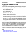
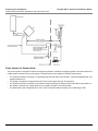
1
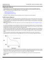
Tsunami MP.11 Family Antenna Installation Guide
Tsunami MP.11 Antenna Installation Guide
Copyright
© 2007 Proxim Wireless Corporation. All rights reserved. Covered by one or more of the following U.S. patents: 5,231,634; 5,875,179;
6,006,090; 5,809,060; 6,075,812; 5,077,753. This guide and the software described in it are copyrighted with all rights reserved. No part of this
publication may be reproduced, transmitted, transcribed, stored in a retrieval system, or translated into any language in any form by any
means without the written permission of Proxim Wireless Corporation.
Trademarks
Proxim is a registered trademark, and Tsunami and the Proxim logo are trademarks, of Proxim Wireless Corporation. All other trademarks
mentioned herein are the property of their respective owners.
Tsunami MP.11 Product Family Antenna Installation Guide
P/N 73922 May 2007
2
Tsunami MP.11 Antenna Installation Guide
Contents
1
Introduction . . . . . . . . . . . . . . . . . . . . . . . . . . . . . . . . . . . . . . . . . . . . . . . . . . . . . . . . . . . . . . . . . . 5
Who Should Use This Guide . . . . . . . . . . . . . . . . . . . . . . . . . . . . . . . . . . . . . . . . . . . . . . . . . . . . . . . . . . . . 5
Safety Precautions . . . . . . . . . . . . . . . . . . . . . . . . . . . . . . . . . . . . . . . . . . . . . . . . . . . . . . . . . . . . . . . . . . . . 7
Finding Additional Information . . . . . . . . . . . . . . . . . . . . . . . . . . . . . . . . . . . . . . . . . . . . . . . . . . . . . . . . . . . 8
Installing Radio Hardware . . . . . . . . . . . . . . . . . . . . . . . . . . . . . . . . . . . . . . . . . . . . . . . . . . . . . . . . . . . . . . . . . . . . 8
Configuration and Management . . . . . . . . . . . . . . . . . . . . . . . . . . . . . . . . . . . . . . . . . . . . . . . . . . . . . . . . . . . . . . . . 8
Safety and Regulatory Information . . . . . . . . . . . . . . . . . . . . . . . . . . . . . . . . . . . . . . . . . . . . . . . . . . . . . . . . . . . . . . 8
Hardware Specifications . . . . . . . . . . . . . . . . . . . . . . . . . . . . . . . . . . . . . . . . . . . . . . . . . . . . . . . . . . . . . . . . . . . . . . 8
Additional Files on Your Product CD . . . . . . . . . . . . . . . . . . . . . . . . . . . . . . . . . . . . . . . . . . . . . . . . . . . . . . . . . . . . 8
Other Sources of Information . . . . . . . . . . . . . . . . . . . . . . . . . . . . . . . . . . . . . . . . . . . . . . . . . . . . . . . . . . . . . . . . . . 8
2
Preparing for Installation . . . . . . . . . . . . . . . . . . . . . . . . . . . . . . . . . . . . . . . . . . . . . . . . . . . . . . . 9
Installation Precautions . . . . . . . . . . . . . . . . . . . . . . . . . . . . . . . . . . . . . . . . . . . . . . . . . . . . . . . . . . . . . . . . 9
Installation Process Overview . . . . . . . . . . . . . . . . . . . . . . . . . . . . . . . . . . . . . . . . . . . . . . . . . . . . . . . . . . 10
Indoor-Mounted Radio Hardware and Cable Overview . . . . . . . . . . . . . . . . . . . . . . . . . . . . . . . . . . . . . . . 11
Indoor Radio Hardware . . . . . . . . . . . . . . . . . . . . . . . . . . . . . . . . . . . . . . . . . . . . . . . . . . . . . . . . . . . . . . . . . . . . . 11
Indoor Radio Cable Setup for an External Antenna . . . . . . . . . . . . . . . . . . . . . . . . . . . . . . . . . . . . . . . . . . . . . . . . 11
Outdoor-Mounted Radio Hardware and Cable Overview . . . . . . . . . . . . . . . . . . . . . . . . . . . . . . . . . . . . . . 14
Outdoor Radio Hardware . . . . . . . . . . . . . . . . . . . . . . . . . . . . . . . . . . . . . . . . . . . . . . . . . . . . . . . . . . . . . . . . . . . . 14
Outdoor Radio Cable Setup for External Antenna . . . . . . . . . . . . . . . . . . . . . . . . . . . . . . . . . . . . . . . . . . . . . . . . . 14
Power Injector for Outdoor Units . . . . . . . . . . . . . . . . . . . . . . . . . . . . . . . . . . . . . . . . . . . . . . . . . . . . . . . . . . . . . . 15
Additional Information for All Models . . . . . . . . . . . . . . . . . . . . . . . . . . . . . . . . . . . . . . . . . . . . . . . . . . . . . 16
Surge Arrestor . . . . . . . . . . . . . . . . . . . . . . . . . . . . . . . . . . . . . . . . . . . . . . . . . . . . . . . . . . . . . . . . . . . . . . . . . . . . 16
Ethernet Cable . . . . . . . . . . . . . . . . . . . . . . . . . . . . . . . . . . . . . . . . . . . . . . . . . . . . . . . . . . . . . . . . . . . . . . . . . . . . 16
3
Installing the Link . . . . . . . . . . . . . . . . . . . . . . . . . . . . . . . . . . . . . . . . . . . . . . . . . . . . . . . . . . . . 17
Required Materials . . . . . . . . . . . . . . . . . . . . . . . . . . . . . . . . . . . . . . . . . . . . . . . . . . . . . . . . . . . . . . . . . . . 17
Determining Optimal Antenna Placement . . . . . . . . . . . . . . . . . . . . . . . . . . . . . . . . . . . . . . . . . . . . . . . . . 19
Mounting the Antenna . . . . . . . . . . . . . . . . . . . . . . . . . . . . . . . . . . . . . . . . . . . . . . . . . . . . . . . . . . . . . . . . 22
Antenna Mast Requirements . . . . . . . . . . . . . . . . . . . . . . . . . . . . . . . . . . . . . . . . . . . . . . . . . . . . . . . . . . . . . . . . . 22
Connecting the Antenna Cable . . . . . . . . . . . . . . . . . . . . . . . . . . . . . . . . . . . . . . . . . . . . . . . . . . . . . . . . . 23
Sealing the Cable Connectors . . . . . . . . . . . . . . . . . . . . . . . . . . . . . . . . . . . . . . . . . . . . . . . . . . . . . . . . . . 24
Grounding the Antenna . . . . . . . . . . . . . . . . . . . . . . . . . . . . . . . . . . . . . . . . . . . . . . . . . . . . . . . . . . . . . . . 25
Aligning the Antenna . . . . . . . . . . . . . . . . . . . . . . . . . . . . . . . . . . . . . . . . . . . . . . . . . . . . . . . . . . . . . . . . . 26
Audible Antenna Alignment . . . . . . . . . . . . . . . . . . . . . . . . . . . . . . . . . . . . . . . . . . . . . . . . . . . . . . . . . . . . . . . . . . 26
Antenna Alignment using the CLI . . . . . . . . . . . . . . . . . . . . . . . . . . . . . . . . . . . . . . . . . . . . . . . . . . . . . . . . . . . . . . 27
Antenna Alignment using Link Test . . . . . . . . . . . . . . . . . . . . . . . . . . . . . . . . . . . . . . . . . . . . . . . . . . . . . . . . . . . . 27
Antenna Polarization . . . . . . . . . . . . . . . . . . . . . . . . . . . . . . . . . . . . . . . . . . . . . . . . . . . . . . . . . . . . . . . . . . . . . . . 27
Antenna Cable Routing . . . . . . . . . . . . . . . . . . . . . . . . . . . . . . . . . . . . . . . . . . . . . . . . . . . . . . . . . . . . . . . . . . . . . 28
3
Tsunami MP.11 Antenna Installation Guide
4
Determining Range and Clearance . . . . . . . . . . . . . . . . . . . . . . . . . . . . . . . . . . . . . . . . . . . . . . 29
Determining the Outdoor Range . . . . . . . . . . . . . . . . . . . . . . . . . . . . . . . . . . . . . . . . . . . . . . . . . . . . . . . . 29
Maximum Range . . . . . . . . . . . . . . . . . . . . . . . . . . . . . . . . . . . . . . . . . . . . . . . . . . . . . . . . . . . . . . . . . . . . . . . . . . 29
Clearance Factor . . . . . . . . . . . . . . . . . . . . . . . . . . . . . . . . . . . . . . . . . . . . . . . . . . . . . . . . . . . . . . . . . . . . . . . . . . 29
Calculations . . . . . . . . . . . . . . . . . . . . . . . . . . . . . . . . . . . . . . . . . . . . . . . . . . . . . . . . . . . . . . . . . . . . . . . . 32
Calculating Link Budget . . . . . . . . . . . . . . . . . . . . . . . . . . . . . . . . . . . . . . . . . . . . . . . . . . . . . . . . . . . . . . . . . . . . . 32
5
Proxim Technical Services and Support . . . . . . . . . . . . . . . . . . . . . . . . . . . . . . . . . . . . . . . . . 36
Obtaining Technical Services and Support . . . . . . . . . . . . . . . . . . . . . . . . . . . . . . . . . . . . . . . . . . . . . . . . 36
Support Options . . . . . . . . . . . . . . . . . . . . . . . . . . . . . . . . . . . . . . . . . . . . . . . . . . . . . . . . . . . . . . . . . . . . . 37
Proxim eService Web Site Support . . . . . . . . . . . . . . . . . . . . . . . . . . . . . . . . . . . . . . . . . . . . . . . . . . . . . . . . . . . . 37
Telephone Support . . . . . . . . . . . . . . . . . . . . . . . . . . . . . . . . . . . . . . . . . . . . . . . . . . . . . . . . . . . . . . . . . . . . . . . . . 37
ServPak Support . . . . . . . . . . . . . . . . . . . . . . . . . . . . . . . . . . . . . . . . . . . . . . . . . . . . . . . . . . . . . . . . . . . . . . . . . . 37
4
Tsunami MP.11 Antenna Installation Guide
Introduction
1
This Antenna Installation Guide explains how to install and set up an outdoor antenna with Tsunami MP.11 hardware.
The following products are covered in this guide:
•
5054 (MP.11a)
•
954-R
•
2454-R
•
4954-R
•
5054-R
•
5054-R-LR
This guide discusses link budget, range, and obstruction clearance; it does not explain how to erect antenna masts, or
how to install a safety grounding system. These prerequisites must be in place before installing the directional antenna.
See the Tsunami MP.11 Recommended Antennas guide for a list of and specifications for antennas you can use with
Tsunami MP.11 hardware.
See the following sections:
•
Who Should Use This Guide
•
Safety Precautions
•
Finding Additional Information
Who Should Use This Guide
The installation of outdoor wireless links requires technical expertise. You should undertake this installation only if you
meet the following prerequisites:
•
You are a trained installation technician with experience mounting outdoor antennas and surge arrestors.
•
You have experience installing and configuring the network components, such as the radio hardware.
•
You understand, or have a working knowledge of, installation procedures for network operating systems using
Microsoft Windows.
WARNINGS:
• Antenna installation must be provided by a suitably trained professional installation technician or
by a qualified antenna installation service. Installation is not to be attempted by someone not
trained or experienced in this type of work.
• The site prerequisites must be checked by a person familiar with the applicable electrical code
and with other regulations governing this type of installation within the country of use.
• The outdoor antennas to be used with these products are intended for mounting on an antenna
tower, on a roof, or on the side of a building.
As radio regulations differ between the various worldwide countries, it may be that not all of the outdoor solutions
described in this manual are allowed in the country in which you plan to install this equipment.
Local radio regulations or legislation may impose restrictions on the use of specific combinations of:
•
Low-loss antenna cables and outdoor antennas
•
Radio channels selected at the radios that are connected to specific outdoor antennas
5
Introduction
Who Should Use This Guide
Tsunami MP.11 Antenna Installation Guide
NOTE: A basic rule for selecting a combination of cables and antennas is that no combination is allowed unless explicitly
approved in this Antenna Installation Guide. Therefore, always use Tsunami MP.11 Recommended Antennas in
combination with the Determining Range and Clearance chapter to select the correct type of antenna equipment
and to inform your antenna installer and LAN administrator about the impact of regulatory constraints on their job
or activities.
IMPORTANT!
At all times, it is the customer’s responsibility to ensure that an outdoor antenna installation complies with local
radio regulations. If you are not certain about the regulations that apply in your country, consult your local Proxim
Wireless Corporation sales office. The customer must verify that:
•
The antenna installer is aware of these regulations
•
The correct cable type and surge arrestor have been used, according to the instructions described in this
document
Proxim Wireless Corporation and its resellers or distributors are not liable for any damage or violation of
government regulations that may arise from failing to comply with these guidelines.
6
Introduction
Safety Precautions
Tsunami MP.11 Antenna Installation Guide
Safety Precautions
Read this section carefully before beginning the installation. All of the following requirements should be satisfied prior to
starting installation of your outdoor antennas.
DANGER!
Outdoor antennas and antenna cables are electrical conductors. Transients or electrostatic discharges that may
occur at the antenna (such as a lightning strike during thunderstorms) may damage your electronic equipment
and cause personal injury or death to persons touching the exposed metal connectors of the equipment if not
installed properly.
When installing, disconnecting, or replacing one of the cabling components, ensure at all times that each of the
exposed metal connectors of the antenna cabling system are grounded locally during the work.
Do not install this antenna where there is any possibility of contact with high-voltage arc-over from power cables
or service drops to buildings. The antenna, supporting mast, or tower must not be close to any power lines
during installation or removal, or in the event part of the system should accidentally fail. This includes the
installation process. Apply a Danger label to a plainly visible area of the antenna support structure.
Do not climb rooftops in wet or windy conditions, during a thunderstorm, or when the area at which the
equipment is to be installed is covered with ice or snow.
Do not touch antennas, surge arrestors, or antenna cables during a thunderstorm.
Install antennas at a safe distance from power lines or telephone lines. The safe distance should be at least
twice the height of the antenna mast plus the height of the antenna.
Mount antennas in such a manner as to minimize the potential for human contact during normal operation. To
avoid the possibility of exceeding the FCC radio frequency exposure limits, human proximity to the antenna shall
not be less than 20 cm (8 inches) during normal operation.
Verify that the low-loss antenna cable that is to connect the antenna with the surge arrestor, or the Ethernet
cable that is to connect to the surge arrestor, is at least 1 m (3 ft.) away from any high voltage or high current
cable.
Check whether the antenna mast and its guy wires or wall bracket are positioned correctly and secured properly
to the roof or walls. This should also include the confirmation that structure attachments are weatherproof.
Check whether the grounding system for the antenna mast, the Tsunami MP.16 equipment hardware, and the
surge arrestor have been installed. The grounding system must comply with the requirements as described in
Grounding the Antenna and local electrical code requirements.
Always consult a qualified electrician if you are in doubt as to whether the antenna mast, the surge arrestor, and
the hardware are properly grounded.
The antenna cable between the antenna and the surge arrestor must be grounded at all times. If the cable is
disconnected at one end for some reason (for example, to replace the surge arrestor), you must ensure that the
exposed metal connector of the cable is grounded locally during the work.
7
Introduction
Finding Additional Information
Tsunami MP.11 Antenna Installation Guide
Finding Additional Information
Installing Radio Hardware
Antennas typically are used in combination with Tsunami MP.11 radio units. The hardware installation of these radios is
described in the User Guide included with each product.
Configuration and Management
Configuration and management of outdoor radios is accomplished with management tools that come with the systems.
Some examples of management tools are:
•
Web-based (HTTP) management
•
Command Line Interface via Telnet or serial connection
•
Wireless network manager
Safety and Regulatory Information
Consult the Safety and Regulatory Compliance Information guide on the installation CD that comes with your product.
Hardware Specifications
Hardware and radio frequency specifications for the radio units are described in your radio’s Installation and
Management manual. Hardware specifications for the outdoor antennas are listed in the Tsunami MP.11 Recommended
Antennas guide. Both of these documents are found on the product CD.
Additional Files on Your Product CD
All installation CDs that come with your Proxim products include a Release Notes file in the Doc subdirectory. This file
contains information about the software version and drivers. You are advised to print and read the Release Notes file
prior to installing your Proxim products, as it may contain information that was not available when this document was
printed.
Other Sources of Information
You can download all Tsunami MP.11 documentation from the Proxim Support website: http://support.proxim.com. Visit
the website regularly for the latest available information, documentation, software updates, and other Proxim news.
8
Tsunami MP.11 Antenna Installation Guide
Preparing for Installation
2
See the following sections:
•
Installation Precautions
•
Installation Process Overview
•
Indoor-Mounted Radio Hardware and Cable Overview
•
•
–
Indoor Radio Hardware
–
Indoor Radio Cable Setup for an External Antenna
Outdoor-Mounted Radio Hardware and Cable Overview
–
Outdoor Radio Hardware
–
Outdoor Radio Cable Setup for External Antenna
–
Power Injector for Outdoor Units
Additional Information for All Models
–
Surge Arrestor
–
Ethernet Cable
Installation Precautions
For ease of installation, and to ensure your own safety during installation, note the following:
•
Review the Safety Precautions provided in the Introduction chapter.
•
Review all requirements outlined in this chapter.
•
Familiarize yourself with the antenna and the antenna- and radio-specific mounting instructions prior to climbing any
roof or ladder.
•
Verify that you have arranged all safety measures for outdoor installation or rooftop installation.
•
Test all equipment before beginning the actual rooftop installation to determine whether all required equipment and
items are available and functioning properly. To verify the equipment prior to installation, you may first need to follow
the guidelines as described in the documentation that comes with the radio unit.
•
Install the grounding system for the antenna mast, radio hardware, and surge arrestor before connecting the cable
from the radio to the surge arrestor. This protects your system against lightning strikes during installation.
9
Preparing for Installation
Installation Process Overview
Tsunami MP.11 Antenna Installation Guide
Installation Process Overview
The installation process can be summarized in the following steps:
1. Verify that the support structure for the antenna and radio has been connected to the grounding system. If this is not
the case, connect it properly.
2. Mount the antenna to the support structure, following the guidelines as described for your antenna’s documentation.
When mounting multiple antennas on a single mast, use the following methods to minimize the influence of cross-talk
interference between the antennas:
–
Place your antennas as far apart as possible.
–
Alternate the mounting of directional antennas for vertical and horizontal polarization.
3. Connect the antenna cable to the antenna.
4. Route the antenna cable to the surge arrestor that has been installed near the ingress point.
5. Connect the antenna/Ethernet cable to the surge arrestor.
6. Attach the surge arrestor to the N-type female bulkhead connector.
7. Run the Link Test diagnostics of the management tools that come with the radio unit to aim the antenna and verify
optimal placement.
NOTE: You can also use the unit’s Antenna Alignment utilities. See Aligning the Antenna.
8. Once the antenna is correctly positioned, and you have verified the installation works properly, secure all cables and
use weatherproofing tape to seal all outdoor connectors.
NOTE: When you must remove or relocate the antenna, follow the Installation Precautions and Safety Precautions
given in this guide, and follow the steps listed above in exactly the reverse order.
10
Preparing for Installation
Indoor-Mounted Radio Hardware and Cable Overview
Tsunami MP.11 Antenna Installation Guide
Indoor-Mounted Radio Hardware and Cable Overview
Indoor Radio Hardware
Model 5054, 5012-SUI, and 5054-SUI radios are intended for indoor mounting and operation. For these indoor radios, the
antenna cable is connected to the connector pigtail extending from the radio.
The following types of radio devices are used for setting up a wireless link with the 5054, 5012-SUI, and 5054-SUI:
•
Tsunami MP.11 5054 (MP.11a) Base Station Unit (BSU)
•
Tsunami MP.11 5054 (MP.11a) Subscriber Unit (SU)
•
Tsunami MP.11 5054 (MP.11a) Residential Subscriber Unit (RSU)
•
Tsunami MP.11 5012-SUI Subscriber Unit (SU)
•
Tsunami MP.11 5054-SUI Subscriber Unit (SU)
Indoor Radio Cable Setup for an External Antenna
The following items are required on each end of the wireless link:
•
A Base Station on one end and a Subscriber Unit on the other end.
•
A surge arrestor to protect your sensitive equipment from static discharge and transients (optional, but highly
recommended).
•
N-type female-female converter connector (optional, needed only if a surge arrestor is not used, or if an additional
antenna cable is required when a surge arrestor is used, see next bullet).
•
A low-loss antenna cable to connect the indoor radio unit to the surge arrestor (optional, only if the radio unit is not
mounted close to where the cable coming from the antenna enters the building, which is the place where the surge
arrestor must be mounted).
•
A low-loss antenna cable to connect the surge arrestor to the outdoor antenna (if surge arrestor is used), or the unit to
the antenna (if surge arrestor is not used).
•
External antennas (one at each end).
•
A grounding system, as described in Grounding the Antenna.
When the unit is not mounted close to where the antenna cable enters the building (where the surge arrestor must be
mounted), an additional cable between the unit and the surge arrestor is required, plus a female-female converter
connector. If the unit is mounted close to the surge arrestor, the unit can be connected directly to the surge arrestor.
Proxim strongly recommends to use a surge arrestor to protect your sensitive equipment from static discharge and
transients. An exception to this rule is when the antenna is installed in an indoor location. This installation does not
require the use of a surge arrestor. The antenna can be connected directly to the radio unit via a cable and a
female-female converter connector.
All cabling components of the antenna system come with standard-N type connectors. Note that the gender of the
connector is not determined by the connector’s thread, but by its center pin. A solid center pin = male; a hollow center pin
= female.
The following sections describe all the possible combinations of cabling components. The 5012-SUI/5054-SUI is
pictured.
•
Indoor Radio Cable Setup without a Surge Arrestor
•
Indoor Radio Cable Setup with a Surge Arrestor Close to the Unit
•
Indoor Radio Cable Setup with a Surge Arrestor Not Close to the Unit
11
Preparing for Installation
Indoor-Mounted Radio Hardware and Cable Overview
Tsunami MP.11 Antenna Installation Guide
Indoor Radio Cable Setup without a Surge Arrestor
Cabling Component
N-Type Connector
A Radio unit with pigtail
Standard-N male
B Converter connector
Standard-N female on both ends
C Low-loss cable
Standard-N male on both ends
D Antenna
Standard-N female
Indoor Radio Cable Setup with a Surge Arrestor Close to the Unit
Cabling Component
N-Type Connector
A Radio unit with pigtail
Standard-N male
B Surge arrestor
Standard-N female on both ends
C Low-loss cable
Standard-N male on both ends
D Antenna
Standard-N female
Indoor Radio Cable Setup with a Surge Arrestor Not Close to the Unit
12
Preparing for Installation
Indoor-Mounted Radio Hardware and Cable Overview
Cabling Component
Tsunami MP.11 Antenna Installation Guide
N-Type Connector
A Radio unit with pigtail
Standard-N male
B Converter connector
Standard-N female on both ends
C Low-loss cable
Standard-N male on both ends
D Surge arrestor
Standard-N female on both ends
E Low-loss cable
Standard-N male on both ends
F Antenna
Standard-N female
Indoor Radio Cabling Precautions
Note that prior to mounting the radio unit, you are advised to carefully calculate:
•
The distance between the intended location of your unit and the location of the antenna mast
•
The height of the antenna on the mast
If the low-loss antenna cable for the unit is not long enough to cover this distance, you either can select another cable
length from the Proxim’s low-loss cable offering, or select another location that satisfies the requirements previously
listed to mount your unit. The radio unit can be placed anywhere, as long as Ethernet cable length allows. Because the
length of the antenna cable can affect the actual range of your outdoor antenna installation, Proxim recommends
selecting another location or using a different radio model.
WARNING: You must not change the length of the low-loss antenna cable used with the radio unit to a length
shorter than allowed by the radio’s certifications. Shortening the cable voids the Proxim Wireless
Corporation warranty and can conflict with radio certifications or approvals.
CAUTION: The radio hardware, the surge arrestor, and the antenna mast must be connected to the same grounding
system.
13
Preparing for Installation
Outdoor-Mounted Radio Hardware and Cable Overview
Tsunami MP.11 Antenna Installation Guide
Outdoor-Mounted Radio Hardware and Cable Overview
Outdoor Radio Hardware
The MP.11 954-R, 2454-R, 5054-R, 5054-R-LR, and 4954-R Base Station Units and Subscriber Units are intended for
outdoor mounting and operation. Outdoor units are referred to collectively as MP.11-R units.
To make optimal use of the units, you must find a suitable location for the hardware. The radio range largely depends
upon the position of the antenna. Because of this Proxim recommends you do a site survey.
The following three types of radio devices are used for setting up a wireless link:
•
Tsunami MP.11-R Base Station Unit (BSU) with external antenna connector
•
Tsunami MP.11-R Subscriber Unit (SU) with external antenna connector
•
Tsunami MP.11-R Subscriber Unit (SU) with integrated antenna for outdoor use
Outdoor Radio Cable Setup for External Antenna
The following items are required on each end of the wireless link:
•
A Base Station or a Subscriber Station
•
A low-loss antenna cable to connect the radio unit to the external antenna (for units using an external antenna
connector only).
NOTE: Proxim recommends an LMR-600 cable (2 meters), available from Proxim Wireless Corporation.
•
A surge arrestor for the CAT5 Ethernet cable that connects the power supply to the radio.
•
Outdoor antenna (for use with units equipped with an external connector only).
•
A grounding system, as described in Grounding the Antenna.
When the BSU and SU are equipped with external antenna connectors, the radios are connected through the RF cable to
an external antenna. The recommended RF cable length is two meters. This is not needed for the SU with the integrated
antenna. The Ethernet cable is connected from the radio to the Ethernet surge arrestor. The surge arrestor is located on
the outside of the building (with proper grounding) very near to the point where the cables enter the building. An outdoor
rated CAT5 Ethernet cable should be used.
CAUTION: The Tsunami MP.11-R hardware, the surge arrestor, and the antenna mast must be connected to the same
grounding system as prescribed by local electrical codes.
The following is an overview of the cable setup for the outdoor antenna.
14
Preparing for Installation
Outdoor-Mounted Radio Hardware and Cable Overview
Tsunami MP.11 Antenna Installation Guide
Power Injector for Outdoor Units
The power injector is designed for indoor mounting and operation. In addition to supplying power to the radio unit there is
a data output connection on the power supply. The ideal location must satisfy the following requirements:
•
The location provides a connection to a grounding type AC wall outlet (100-240 VAC), using the standard power cord
supplied with the unit.
•
The location must allow for easy disconnection of the power supply from the AC wall outlet.
•
The location provides a connection to the network backbone through an Ethernet CAT5 cable that is connected to a
hub, bridge, or directly into a patch panel or to a computer through a null modem cable.
•
The ideal location has a temperature of 0–55º C and a maximum relative humidity (non-condensing) of 95%.
15
Preparing for Installation
Additional Information for All Models
Tsunami MP.11 Antenna Installation Guide
Additional Information for All Models
Surge Arrestor
The surge arrestor is an indispensable part of your outdoor radio installation. It protects your sensitive electronic
equipment from transients or electrostatic discharges at the antenna.
For optimal protection, the surge arrestor must be installed at a location that is very near to where the CAT5 Ethernet
cable enters inside the structure. This location should allow proper grounding complying with local electrical code
requirements.
Ethernet Cable
The antenna cable must be connected from the antenna through the surge arrestor to the antenna connector of the unit.
To plan the route of the antenna cable for an indoor unit (5054), consider the following:
•
Does the cable route require drilling through a wall or ceiling?
•
Do you have a building plan of the desired location showing other cabling routes such as electricity, telephone or
networking?
•
Does the type of building materials require special drilling tools?
The cable should not be installed into tight positions, as bending or applying excessive force to the connectors can
damage the antenna cable. Always allow the cable to bend naturally around corners. The recommended bend radius is
at least 100 mm (4 in) or more for the low-loss cable of 10 mm (0.4 in) and 15 mm (0.6 in) diameter.
CAUTION:
•
The cable must be secured along the complete distance between attachment points. No part of the
antenna cable should be allowed to hang free. This is particularly important for outdoor cable parts.
•
The antenna cable and cable connectors are not designed to withstand excessive force:
– Do not use the connectors as ‘cable grips’ to pull cable through raceways or conduits.
– Do not use the cable connector to support the weight of the cable during or after installation.
– Do not use any tool to tighten the connectors.
•
Always seal the connectors using weatherproofing tape.
•
Avoid any water or moisture entering the cable as that impacts the performance of the wireless link.
•
Prior to sealing the outdoor connectors and permanently securing the cable to the wall with cable ties
and wall hooks, verify whether the installation and all components functions properly.
16
Tsunami MP.11 Antenna Installation Guide
3
Installing the Link
See the following sections:
•
Required Materials
•
Determining Optimal Antenna Placement
•
Mounting the Antenna
–
Antenna Mast Requirements
•
Connecting the Antenna Cable
•
Sealing the Cable Connectors
•
Grounding the Antenna
•
Aligning the Antenna
–
Audible Antenna Alignment
–
Antenna Alignment using the CLI
–
Antenna Alignment using Link Test
–
Antenna Polarization
–
Antenna Cable Routing
Required Materials
The outdoor installation of the link requires the following:
•
An antenna or unit with an integrated antenna
•
A low-loss antenna cable (for units with external antennas only)
NOTE: Proxim recommends an LMR-600 cable (2 meters), available from Proxim Wireless Corporation.
•
Antenna mast or wall bracket for the antenna/unit
•
A grounding system that meets the local electrical code requirements
•
Waterproofing of all connections (see Sealing the Cable Connectors)
DANGER!
For your own safety, the antenna mast and the grounding system should be installed only by experienced
installation professionals who are familiar with local building, safety, and electrical codes in the country of use.
17
Installing the Link
Required Materials
Tsunami MP.11 Antenna Installation Guide
IMPORTANT!
Before climbing the roof to begin installation, check whether you have all the required components to set up an
outdoor wireless link. For each side of the link, you will need:
•
Radio unit with integrated antenna; OR radio unit with external antenna connector, external antenna, and
antenna-to-radio connection cable(s)
•
Tools and material to mount the antenna
•
Tape or wraps to attach the antenna cable, for example, to the mast
•
Ethernet cable with waterproof cap
•
Proper tools to allow system installation
•
Radio, antenna, and antenna support grounding material that meets local electrical requirements
18
Installing the Link
Determining Optimal Antenna Placement
Tsunami MP.11 Antenna Installation Guide
Determining Optimal Antenna Placement
To achieve maximum performance of your wireless outdoor link, the outdoor antenna must have clear line-of-sight to the
antenna of the other unit. Although the radio signal can work well without line-of-sight in urban environments in which the
signal is transported by reflection rather than being direct, the best results are achieved in line-of-sight conditions.
Line-of-sight is defined as:
•
No obstacles in the direct path between the antennas (antenna beam)
•
No obstacles within a defined zone around the antenna beam
You should be aware that the shape of an antenna beam is not straight and narrow like a laser beam. The antenna beam
contains a bulged area known as Fresnel Zone.
The 1st Fresnel zone is an imaginary boundary line offset along the direct signal path. This boundary is defined as the
point where, if a signal were reflected between the two antennas, it would travel a distance exactly one-half wavelength
longer than the direct-path signal. Each succeeding Fresnel zone boundary adds an additional half-wavelength to the
reflected path distance between the antennas.
Signals reflected from any even-numbered Fresnel zone result in signal cancellation; those from odd-numbered Fresnel
zones add to the direct path signal.
The exact shape and width of the Fresnel Zone is determined by the path length and frequency of the radio signal. The
width as distance from the direct antenna beam is approximately 6.8 m in the middle of the wireless link for a distance of
6 Km and a frequency of 3.5 GHz. This width is also the required clearance of the antenna beam from obstacles in its
path, to avoid loss of radio signal.
When any significant part of this zone is obstructed, a portion of the radio energy is lost, resulting in reduced
performance. Reduced performance can also occur when obstacles close to the antenna beam cause signal reflections
or noise that interfere with the radio signal.
For optimal performance, you must ensure that the type and placement of the antennas leave sufficient clearance of the
Fresnel Zone at the maximum width of the bulge, which is typically at the mid-point between the antennas. See
Determining the Outdoor Range.
The following figure shows some typical examples of obstacles you must avoid for the directional antenna to operate
effectively:
a. Neighboring buildings
b. Trees or other obstructions
c. Power lines
19
Installing the Link
Determining Optimal Antenna Placement
Tsunami MP.11 Antenna Installation Guide
To minimize the influence of obstacles, signal interference, or reflections, note the following guidelines:
•
Mount the antenna as high as possible above the ground to allow maximum clearance:
–
In open areas, ground is the actual surface of the earth.
–
In dense urban areas, ground is to be interpreted as the height of the highest obstacle in the signal path between
the two antenna sites.
•
Avoid trees in the signal path to avoid signal absorption due to seasonal changes (leaves or ice).
•
Install the antenna at least 2 m (6 ft.) away from all other antennas.
Other situations in which reflections of the radio signal may cause interference are environments in which large reflecting
surfaces exist in parallel or partly perpendicular to the antenna beam.
Environments with large reflective surfaces include:
•
Mirror-glass buildings
•
Crowded parking lots
•
Water surface or moist earth and moist vegetation
•
Above ground power and telephone lines
NOTE: The use of reflective surfaces can be used to improve a link, especially if the direct line-of-sight is impaired or
absent.
Weather conditions such as rain or snow usually do not have much impact on the performance of your Proxim product,
provided you have sealed all cable connectors with weatherproofing tape.
Seasonal influence on signal propagation can occur in the following situations:
•
A marginal communications quality in late fall (with no leaves on the trees in the signal path) might fail in the summer
when leaves are present.
•
In winter, a wireless link can fail when the antenna is exposed to ice buildup or when the antenna elements are
covered with snow.
Radio paths over water or extremely flat ground may require optimization of antenna height at one end. This is due to
in-phase or out-of-phase reflections. Adjustment of antenna height by 1 to 3 meters may move the signal from a null to a
peak.
20
Installing the Link
Determining Optimal Antenna Placement
Tsunami MP.11 Antenna Installation Guide
Long distance links may be obstructed by earth curvature, so the antenna height requirements must not only take the
height of obstructions and Fresnel Zone into account, but also earth bulge. The earth bulge is approximately 5 m (16.4
ft.) at a link distance of 16 Km (10 mi.).
In these cases, consult your supplier to take appropriate steps to maintain or optimize wireless link performance.
21
Installing the Link
Mounting the Antenna
Tsunami MP.11 Antenna Installation Guide
Mounting the Antenna
NOTE: As the mounting procedures for the various antennas differ from one another, consult the documentation you
received from the manufacturer for mounting procedures.
Proxim offers multiple antennas to set up a wireless link. See the Tsunami MP.11 Recommended Antennas guide.
When mounting multiple antennas on a single mast, use the following methods to minimize the influence of cross-talk
interference between the antennas:
•
Place your antennas as far apart as possible
•
Alternate the mounting of directional antennas for vertical and horizontal polarization
There are two frequently used methods to erect an antenna mast:
•
Tripod Mount: The tripod mount is used primarily on peaked and flat roofs. The antenna mast must be secured to the
roof using three or four guy wires equally spaced around the mast. When the height of the antenna mast is more than
3 meters (10 ft.), you should use at least three guy wires for each 3-meter (10-foot) section of the mast.
•
Wall (Side) Mount: A wall (side) mount allows for mounting an antenna (mast) on the side of a building or on the side
of an elevator penthouse. This provides a convenient mounting location when the roof overhang is not excessive or
when the location is high enough to provide a clear line-of-sight.
In most situations mounting an antenna directly to the wall does not let you align the antenna properly with the
corresponding antenna at the opposite end of your wireless link. As poor alignment typically results in poor
performance, Proxim recommends always mounting the antennas to a mast.
Antenna Mast Requirements
To accommodate the antennas, the antenna mast must satisfy the following requirements:
•
The construction of the mast must consist of sturdy, weatherproof, and non-corrosive material (for example,
galvanized or stainless steel construction pipe).
•
Typical diameter of the mast should be between 35 mm (1.4 in) and 41 mm (1.6 in). Depending upon the type of
antenna you intend to install, other diameters also may be possible.
•
The height of the antenna mast must be sufficient to allow the antenna to be installed at least 1.5 m (5 ft.) above the
peak of the roof. If the roof is of metal, the height of the antenna should be at least 3 m (10 ft.) above the roof.
•
The mast or wall bracket must be free from any substance that may prevent a good electrical connection with the
antenna (for example, paint).
22
Installing the Link
Connecting the Antenna Cable
Tsunami MP.11 Antenna Installation Guide
Connecting the Antenna Cable
Once the antenna is properly mounted, you can connect the antenna to the radio.
1. Connect the antenna cable to the antenna.
2. Secure the antenna cable to the mast so that the cable connectors do not support the full weight of the cable.
3. Connect the opposite end of the antenna cable to the radio.
CAUTION: To avoid damage to the antenna cable and connectors, do not use tools to tighten the cable connectors.
4. Prior to securing the cable along its complete length, run the Link Test diagnostics of the management tools that come
with the unit to analyze wireless performance and optimal placement of the outdoor antenna. Use of this tool is
described in the documentation that comes with the radio unit and also can be downloaded from the Proxim support
website at http://support.proxim.com.
5. If required, adjust the direction of the antenna.
6. Once the installation has been fully tested, tighten the nuts of the antenna to lock the antenna into its position.
CAUTION: Avoid over-tightening of the connector, and the nuts and screws used to mount the antenna, to prevent
damage to your antenna and radio hardware.
7. Secure the cable along its complete length with cable ties or electrical tape to relieve strain on the antenna connector
properly. No part of any cable should be allowed to hang free. This is especially important for those parts that are
routed outside the building.
8. Proceed as described in the next section to weatherproof all outdoor connectors.
23
Installing the Link
Sealing the Cable Connectors
Tsunami MP.11 Antenna Installation Guide
Sealing the Cable Connectors
Most problems associated with wireless outdoor installations are related to degrading performance due to corrosion of
the antenna cable and cable connectors. To avoid this type of problem, you must always seal the cable connectors that
are located outdoors using weatherproofing tape.
You are advised to seal the connectors only after you have verified optimal alignment of the antennas using the Link Test
as described in the documentation that comes with the radio unit. Doing so lets you adjust antenna placement and cable
routing without removing the tape.
To weatherproof the connectors:
1. Prepare the cable and connectors so that they are dry and free from dust, dirt and grease.
2. Attach the tip of the weatherproofing tape to the cable just above the connector. Holding the tape in its position,
stretch the tape and wind it half-overlapped around the cable and connectors to form a void-free joint. The degree of
stretch may vary in different sections of the joint, as long as the overlaps accomplish a void-free application.
3. To protect the weatherproofing stretch tape from the effects of Ultra-Violet (UV) radiation (for example, from direct
sunlight), protect the joint with two half-overlapped layers of any vinyl plastic electrical tape. Alternatively, apply
silicone sealer to protect the weatherproofing tape from sunlight, rain and other weather conditions.
24
Installing the Link
Grounding the Antenna
Tsunami MP.11 Antenna Installation Guide
Grounding the Antenna
Direct grounding of the antenna mast, radio hardware, and surge arrestor is extremely important.
NOTE: A safety grounding system is necessary to protect your radio hardware from lightning strikes and the build-up of
static electricity.
WARNINGS:
• The antenna mast, radio hardware, and surge arrestor must be connected to the same ground,
using an equi-potential bonding conductor.
• A good electrical connection should be made to one or more ground rods, using at least a 10AWG
ground wire and non-corrosive hardware.
• The grounding system must comply with the safety standards that apply in your country. Always
check with a qualified electrician if you are in doubt whether your radio hardware installation is
properly grounded.
25
Installing the Link
Aligning the Antenna
Tsunami MP.11 Antenna Installation Guide
Aligning the Antenna
Antenna alignment is a process to physically align the antennas of both units to have the best possible radio link
established between them. The antenna alignment process usually is performed during installation and after major
repairs. The following methods are available to help you align the antenna:
•
Audible Antenna Alignment
•
Antenna Alignment using the CLI
•
Antenna Alignment using Link Test
Alternatively, consult a professional Antenna Installation Service to optimize the antenna alignment.
Audible Antenna Alignment
MP.11-R models (954-R, 2454-R, 5054-R, 5054-R-LR, and 4954-R) have an audible antenna alignment tool that can be
activated by plugging in the supplied serial dongle (supplied with every Base Station) or by issuing the CLI command for
antenna alignment. The CLI command causes both audible and numerical feedback as the CLI shows the running SNR
values twice a second.
NOTE: Model 5054 has the SNR value output on the CLI but not the audible output (see Antenna Alignment using the
CLI).
The output from the beeper for antenna alignment consists of short beeps with a variable interval. The interval changes
with the SNR level to assist in correctly aligning the antenna. An increase in signal level is indicated by a shorter interval
between beeps; a reduction in signal level results in beeps further apart.
To allow for precise antenna alignment, small changes in SNR result in large changes in the beep period. The alignment
process averages the SNR, which is represented by an average length beep. When a higher SNR is received, the beep
period is made shorter, dependent upon the difference to the average. A lower SNR results in a longer period between
beeps.
The first five steps are represented by a large change and all following steps are a small change. This acts as if a
magnifying glass is centered around the average SNR and the values next to the average are significantly different.
When the antenna is aimed, the beep can easily be heard if the SNR is rising (shorter period, higher frequency) or falling
(longer period). When the position of the antenna has been changed, the SNR averaging settles at the new value and the
beeping returns to the average length so the antenna can again be aimed towards rising SNR.
Aiming is complete if moving in any direction results in a falling SNR value, which can be heard as longer periods
between beeps.
NOTE:
26
Installing the Link
Aligning the Antenna
Tsunami MP.11 Antenna Installation Guide
• Antenna alignment for the Base Station is useful only for a point-to-point link.
• The range of the average SNR is limited to values from 0 to 48. Anything over 48 is capped at 48.
• AAD is automatically disabled 30 minutes after it is enabled to remove the load of extra messages on the
wireless interface. The default telnet timeout is 900 seconds (15 minutes). If AAD must run for the entire 30
minutes, change the default telnet timeout value greater than 30 minutes (greater than 1800 seconds). This
restriction is for telnet connections only and not for the serial interface. The serial interface never times out.
Antenna Alignment using the CLI
Use the following commands to align the antenna using the CLI:
•
set aad enable local
Enables display of the local SNR. Local SNR is the SNR measured by the receiver at the near end.
•
set aad enable remote
Enables display of the remote SNR. Remote SNR is the SNR as measured by the receiver at the far end.
•
set aad enable average
Enables display of the average SNR. The average SNR is the average of the local and remote SNR.
•
set aad disable
Disables Antenna Alignment Display (Ctrl-C also disables AAD).
Antenna Alignment using Link Test
On MP.11-R units, use the Link Test option of the management tools that come with the radio unit to analyze the radio
link quality. The Link Test option lets you display the radio signal strength in relation to the noise in the signal path. If
required, you can interactively optimize the antenna alignment with the Link Test, by making small modifications in the
antenna orientation.
The Link Test provides SNR, Signal, and Noise information, as shown below. Link Test stops when you close the Link
Test page.
Antenna Polarization
Outdoor antennas are standard-mounted for vertical polarization.
In some cases, you might consider mounting the antenna for horizontal polarization; for example, to minimize the
influence of cross-talk between antennas when:
•
You plan to mount multiple directional antennas to the same mast.
•
Your wireless link receives interference from a vertically polarized neighboring installation.
NOTE: For optimal wireless link performance, you must always verify that the antenna polarization on both ends of the
wireless link is the same.
27
Installing the Link
Aligning the Antenna
Tsunami MP.11 Antenna Installation Guide
Antenna Cable Routing
The antenna cable must be routed and fixed in such a way that installation technicians have a clear passage area.
All connectors that are located outdoors must have a weatherproof seal. You are advised to seal connectors only after
you have completed the final radio test.
28
Tsunami MP.11 Antenna Installation Guide
Determining Range and Clearance
4
See the following sections:
•
•
Determining the Outdoor Range
–
Maximum Range
–
Clearance Factor
Calculations
–
Calculating Link Budget
Determining the Outdoor Range
The range of your outdoor antenna installation is closely related to a number of different factors. To let you determine the
range of the antenna system in your situation, use the following formula:
Range = Maximum Range x Clearance Factor
where:
•
Maximum Range is the theoretical maximum that can be achieved under optimal circumstances using the available
Tsunami MP.16 products according to their specifications and in compliance with local radio regulations.
•
Clearance Factor is a correction value (in percentage) that should be used in case the signal path of your wireless
link does not provide the minimum clearance as listed in the Maximum Range table (see Clearance Factor).
NOTE: You also can use a calculation sheet provided by Proxim to generate an estimate of link distance and reliability.
Maximum Range
The maximum range of your system is based upon:
•
The type of outdoor antenna equipment
•
The data speed of the wireless link
•
The clearance of the signal path (see Clearance Factor)
•
The values in this section are based upon calculations that assume optimal radio conditions. They do not represent
a guarantee that the same maximum distance can be achieved at your location. Differences in performance figures
can result from:
–
Incorrect alignment of antennas (see Aligning the Antenna)
–
Polarization mismatch of the antennas
–
Sources of interference or unexpected reflections in the signal path that affect the communications quality (see
Determining Optimal Antenna Placement)
–
Severe weather conditions such as heavy rain or snow fall, or strong winds
–
Unexpected obstacles in the link path
–
Seasonal influences such as leaves on trees, or icing on the antennas
Clearance Factor
For optimal performance of your outdoor wireless link, the signal path between the BSU and SU must provide sufficient
clearance.
NOTE: An outdoor wireless link that lacks sufficient clearance will suffer from poor performance, which is typically
perceived as slow network response times. Although your radio equipment automatically retransmits every lost
29
Determining Range and Clearance
Determining the Outdoor Range
Tsunami MP.11 Antenna Installation Guide
data frame due to an out-of-range situation or frame collision, the larger the number of retransmissions, the lower
the throughput efficiency of your wireless link.
This section explains how to determine the clearance that applies in your environment and (if applicable) the effect of
insufficient clearance on the range of your outdoor wireless link.
If any significant part of the antenna beam is obstructed, a portion of the radio energy is lost, which can affect the
performance of your wireless link in terms of maximum range and transmit rate.
a
BSU
b
SS
SU
In the figure above, you see two variables that determine the shape of the antenna beam, also referred to as Fresnel
Zone:
•
The distance between the antennas (a)
•
The clearance required for optimal performance (b), where clearance should be interpreted as:
–
Vertical clearance above the ground and the highest buildings or objects in the signal path
–
Horizontal clearance from neighboring buildings and objects in the signal path
For optimal range and throughput performance, you must ensure that your antenna installation provides maximum
clearance in both horizontal and vertical direction.
Clearance should be interpreted as follows:
•
In open areas without obstacles in the signal path, clearance is measured as height above the surface of the earth.
For example, if the antenna is mounted on the roof, this height includes the height of the building plus the height of the
mast above the rooftop.
•
In areas with obstacles in the signal path between the two antennas, clearance should be measured as height above
the highest obstacle in the signal path.
•
In dense urban areas, the clearance should be measured as height above the highest rooftop or any other obstacles
in the signal path between the two antennas.
For situations in which local authorities, the proprietor of the premises, or other factors do not let you set up an antenna
mast that lets you meet the listed clearance requirements, you may be unable to achieve a full line-of-sight clearance. At
the same time, however, when the distance that your wireless outdoor installation must cover is less than the listed
maximum range, you may not need full clearance.
To determine the effect of insufficient signal path clearance, you must determine the Clearance Factor as described
below, and calculate its effect on the range for your antenna installation using the formula described in Determining the
Outdoor Range.
•
If the clearance for your antenna installation is equal to or better than the minimum clearance requirement, the
Clearance Factor for your installation is 100%.
30
Determining Range and Clearance
Determining the Outdoor Range
•
Tsunami MP.11 Antenna Installation Guide
If your actual clearance is less than the minimum clearance, use the diagram depicted in the following figure to
determine the actual range that applies in your situation.
NOTE: The Clearance Factor Diagram should be used as a rule-of-thumb for estimating the probable range in case the
clearance requirements are not fully met. In real life, you will also find it almost impossible to achieve maximum
range due to interference from other radio products.
31
Determining Range and Clearance
Calculations
Tsunami MP.11 Antenna Installation Guide
Calculations
Availability of the microwave path is a prediction of the percent of time that the link operates. In the absence of direct
interference, availability is affected by the following:
•
Path length
•
Fade margin
•
Frequency
•
Terrain (smooth, average, mountainous)
•
Climate (dry, temperate, humid)
Depending upon the type of information carried over the link and the overall network design redundancy, you may want to
design for a specific availability rate. For example, if the data or voice traffic carried by the radio is critical, the link can be
designed for a very high availability rate (for example, 99.999% or 5.3 minutes of predicted outage per year).
Availability can be improved by increasing the fade margin either by making the path shorter or by using the higher gain
antennas in conjunction with lower loss antenna cable (using a higher quality antenna cable, shortening the length, or
both).
Calculating Link Budget
Use the calculator provided on the Proxim Wireless Web site to calculate link budget. Use the following formula to
estimate the received signal level (RSL):
RSL (dBm) = Pout - L1+ G1 + G2 - L2 - Lp
where:
•
Pout is the transmitter output power (in dBm)
•
L1 is the total loss of all transmission elements between the antenna and the RF Unit on one side of the link (in dB)
•
G1 is the gain of the antenna on one side of the link (in dB)
•
G2 is the gain of the antenna on the opposite side of the link (in dB)
•
L2 is the total loss of all transmission elements between the antenna and the RF Unit on the opposite side of the link
(in dB)
•
Lp is the Path loss, defined by: Lp (dB) = 96.6 + 20 log10F + 20 log10D
where:
–
F is the Frequency of the radio system in GHz (3.5 GHz)
–
D is the Distance of the path in miles
NOTE: This formula is available on a calculation sheet provided by Proxim to generate an estimate of link distance and
reliability.
See the following figure for a visual representation of the elements of this equation.
32
Determining Range and Clearance
Calculations
Tsunami MP.11 Antenna Installation Guide
Procedure
1. Start with the transmit power and the number of the channel to be used in dBm. Subtract the total loss of all
transmission elements between the antenna and the radio on one side of the link (dB).
2. Add the dBi of the antenna you will be using. The total is the EIRP (equivalent isotropically radiated power).
3. Determine your link budget from the Distance and Link Budget table.
4. Add the gain of the antenna on the second side of the link.
5. Subtract the total loss of all transmission elements between the antenna and the radio on the second side of the link.
The result is the Received Signal Level (RSL).
6. From the Receiver Sensitivity tables in your radio’s Installation and Management Manual’s “Technical Specifications”
appendix, find the dBm value for the data rate used for the link.
7. Subtract this value from the Received Signal Level; this is the Fade Margin.
NOTES:
• The RSL must be higher than the Receiver Sensitivity plus the fade margin for a good link. The amount of Fade
Margin indicates the reliability of the link; the more Fade Margin, the more reliable the link.
• The path loss must be smaller than the link budget minus the minimum required fade margin. The maximum
ranges cause the path loss plus the fade margin to be the same as the link budget.
The results of this link budget calculation are very important for determining any potential problems during installation. If
you have calculated the expected RSL, you can verify that it has been achieved during installation and troubleshooting, if
necessary.
33
Determining Range and Clearance
Calculations
Tsunami MP.11 Antenna Installation Guide
In the USA and Canada, this model radio can be installed with any gain directional antennas, as there is no Effective
Isotropic Radiated Power (EIRP) limit for the application of these systems for fixed point-to-point applications in the 5.8
GHz frequency band. In other bands and in other countries, EIRP limits may apply.
In the case of EIRP limits, use the lesser of either (Pout - L1+ G1) or the EIRP limit within the previous equation. You
should check this calculation in both directions to assure legal application. An EIRP limit is the maximum RF energy that
can be transmitted, as measured at the transmitting antenna, and is usually determined by government regulations.
Proxim’s recommendation is to keep at least 60-70% of the first Fresnel zone free. If the clearance is lower than this
percentage, the link budget and achieved fade margin are affected. Clearances more than 100% of the Fresnel zone can
cause reflections that are 180 degrees out of phase and can cancel out the signal. The Fresnel zone works in both the
horizontal and vertical paths.
Tables for output levels can be found in the “Technical Specifications” appendix in your radio’s Installation and
Management manual.
Table 4-1 Examples of Minimum Antenna Cable Loss
Frequency Band
5.25-5.35 GHz
5.25-5.35 GHz
5.25-5.35 GHz
5.25-5.35 GHz
5.725-5.85 GHz
5.725-5.85 GHz
5.725-5.85 GHz
5.725-5.85 GHz
5.725-5.85 GHz
5.725-5.85 GHz
5.725-5.85 GHz
5.725-5.85 GHz
5.47-5.725 GHz
5.47-5.725 GHz
5.47-5.725 GHz
5.47-5.725 GHz
Antenna
Gain
10
17
23
31
10
17
23
31
10
17
23
31
10
17
23
31
TPC
Setting
0
-6
-10
-10
0
0
-6
-10
0
0
0
0
0
-6
-10
-10
Minimum Cable Loss for
Data up to 24 Mbps*
0
0
1.5
9.5
0
0
0
3.5
0
0
0
0
0
0
1.5
9.5
EIRP
28.5
29.5
30
30
28.5
35.5
35.5
36
28.5
35.5
41.5
49.5
28.5
29.5
30
30
Deployment
USA
USA
USA
USA
USA, PtMP
USA, PtMP
USA, PtMP
USA, PtMP
USA, PtP
USA, PtP
USA, PtP
USA, PtP
ETSI
ETSI
ETSI
ETSI
* Note that higher data rates use lower output power, so less cable loss is required to meet the maximum EIRP limit.
34
Determining Range and Clearance
Calculations
Tsunami MP.11 Antenna Installation Guide
Table 4-2 Distance and Link Budget
Link Budget
(dB)
61
62
63
64
65
66
67
68
69
70
71
72
73
74
75
76
77
78
79
80
81
82
83
84
85
86
87
88
89
90
Distance
(m)
4.8
5.4
6.0
6.8
7.6
8.5
9.5
11
12
13
15
17
19
21
24
27
30
34
38
43
48
54
60
68
76
85
95
107
120
135
Reference Frequency: 5600 MHz Center Frequency for Europe
Fresnel Link Budget Distance
Fresnel
Link
Zone (m)
(dB)
(m)
Zone (m) Budget (dB)
0.3
91
151
1.4
121
0.3
92
170
1.5
122
0.3
93
190
1.6
123
0.3
94
214
1.7
124
0.3
95
240
1.8
125
0.3
96
269
1.9
126
0.4
97
302
2.0
127
0.4
98
339
2.1
128
0.4
99
380
2.3
129
0.4
100
426
2.4
130
0.5
101
478
2.5
131
0.5
102
537
2.7
132
0.5
103
602
2.8
133
0.5
104
676
3.0
134
0.6
105
758
3.2
135
0.6
106
850
3.4
136
0.6
107
954
3.6
137
0.7
108
1071
3.8
138
0.7
109
1201
4.0
139
0.8
110
1348
4.2
140
0.8
111
1512
4.5
141
0.8
112
1697
4.8
142
0.9
113
1904
5.0
143
1.0
114
2136
5.3
144
1.0
115
2397
5.7
145
1.1
116
2689
6.0
146
1.1
117
3018
6.4
147
1.2
118
3386
6.7
148
1.3
119
3799
7.1
149
1.3
120
4263
7.6
150
Distance
(m)
4.8
5.4
6.0
6.8
7.6
8.5
9.5
10.7
12.0
13.5
15.1
17.0
19.0
21.4
24.0
26.9
30.2
33.9
38.0
42.6
47.8
53.7
60.2
67.6
75.8
85.0
95.4
107.1
120.1
134.8
Fresnel
Zone (m)
8.0
8.5
9.0
9.5
10.1
10.7
11.3
12.0
12.7
13.4
14.2
15.1
16.0
16.9
17.9
19.0
20.1
21.3
22.6
23.9
25.3
26.8
28.4
30.1
31.9
33.7
35.7
37.9
40.1
42.5
NOTE: The distance is based upon the assumption that 60% of the 1st Fresnel is clear.
35
Tsunami MP.11 Antenna Installation Guide
Proxim Technical Services and Support
5
See the following sections:
•
Obtaining Technical Services and Support
•
Support Options
–
Proxim eService Web Site Support
–
Telephone Support
–
ServPak Support
Obtaining Technical Services and Support
If you are having trouble utilizing your Proxim product, please review the User Guide and the additional documentation
provided with your product.
If you require additional support and would like to use Proxim’s free Technical Service to help resolve your issue, please
be ready to provide the following information before you contact Proxim’s Technical Services:
•
•
•
Product information
–
Part number of suspected faulty unit
–
Serial number of suspected faulty unit
Trouble/error information:
–
Trouble/symptom being experienced
–
Activities completed to confirm fault
–
Network information (what kind of network are you using?)
–
Circumstances that preceded or led up to the error
–
Message or alarms viewed
–
Steps taken to reproduce the problem
Servpak information (if a Servpak customer):
–
•
Servpak account number
Registration information:
–
If the product is not registered, date when you purchased the product
–
If the product is not registered, location where you purchased the product
NOTE: If you would like to register your product now, visit the Proxim eService Web Site at http://support.proxim.com
and click on New Product Registration.
36
Proxim Technical Services and Support
Support Options
Tsunami MP.11 Antenna Installation Guide
Support Options
Proxim eService Web Site Support
The Proxim eService Web site is available 7x24x365 at http://support.proxim.com.
On the Proxim eService Web Site, you can access the following services:
•
New Product Registration: Register your product for free support.
•
Open a Ticket or RMA: Open a ticket or RMA and receive an immediate reply.
•
Search Knowledgebase: Locate white papers, software upgrades, and technical information.
•
ServPak (Service Packages): Receive Advanced Replacement, Extended Warranty, 7x24x365 Technical Support,
Priority Queuing, and On-Site Support.
•
Your Stuff: Track status of your tickets or RMAs and receive product update notifications.
•
Provide Feedback: Submit suggestions or other types of feedback.
•
Customer Survey: Submit an On-Line Customer Survey response.
•
Repair Tune-Up: Have your existing Proxim equipment inspected, tested, and upgraded to current S/W and H/W
revisions, and extend your warranty for another year.
Telephone Support
Contact technical support via telephone as follows:
•
Domestic: 866-674-6626
•
International: +1-408-542-5390
Hours of Operation
•
North America: 8 a.m. to 5 p.m. PST, Monday through Friday
•
EMEA: 8 a.m. to 5 p.m. GMT, Monday through Friday
ServPak Support
Proxim understands that service and support requirements vary from customer to customer. It is our mission to offer
service and support options that go above-and-beyond normal warranties to allow you the flexibility to provide the quality
of service that your networks demand.
In recognition of these varying requirements we have developed a support program called ServPak. ServPak is a
program of Enhanced Service Options that can be purchased individually or in combinations to meet your needs.
•
Advanced Replacement: This service offers customers an advance replacement of refurbished or new hardware.
(Available in the U.S., Canada, and select countries. Please inquire with your authorized Proxim distributor for
availability in your country.)
•
Extended Warranty: This service provides unlimited repair of your Proxim hardware for the life of the service
contract.
•
7x24x365 Technical Support: This service provides unlimited, direct access to Proxim’s world-class technical
support 24 hours a day, 7 days a week, 365 days a year.
•
Priority Queuing: This service allows your product issue to be routed to the next available Customer Service
Engineer.
To purchase ServPak support services, please contact your authorized Proxim distributor. To receive more information
or for questions on any of the available ServPak support options, please call Proxim Support at +1-408-542-5390 or send
an email to [email protected].
37