1
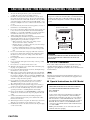
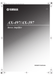
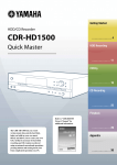
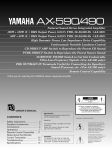
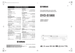
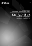
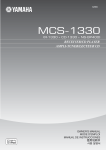
BAL
HOME THEATER SOUND SYSTEM
AVX-S30
(AVC-S30 + NX-S30 + NX-SW30)
OWNER’S MANUAL
CAUTION: READ THIS BEFORE OPERATING YOUR UNIT.
1
2
3
4
5
6
7
8
9
10
11
12
13
14
15
16
17
18
19
To assure the finest performance, please read this manual
carefully. Keep it in a safe place for future reference.
Install this sound system in a well ventilated, cool, dry, clean
place with at least 10 cm on the top, 10 cm on the left and right,
and 10 cm at the back of AVC-S30, and 20 cm on the top, 20 cm
on the left and right, and 20 cm at the back of NX-SW30 — away
from direct sunlight, heat sources, vibration, dust, moisture, and/
or cold.
Locate this unit away from other electrical appliances, motors, or
transformers to avoid humming sounds.
Do not expose this unit to sudden temperature changes from cold
to hot, and do not locate this unit in an environment with high
humidity (i.e. a room with a humidifier) to prevent condensation
inside this unit, which may cause an electrical shock, fire,
damage to this unit, and/or personal injury.
Avoid installing this unit where foreign object may fall onto this
unit and/or this unit may be exposed to liquid dripping or
splashing. On the top of this unit, do not place:
– Other components, as they may cause damage and/or
discoloration on the surface of this unit.
– Burning objects (i.e. candles), as they may cause fire, damage
to this unit, and/or personal injury.
– Containers with liquid in them, as they may fall and liquid
may cause electrical shock to the user and/or damage to this
unit.
Do not cover this unit with a newspaper, tablecloth, curtain, etc.
in order not to obstruct heat radiation. If the temperature inside
this unit rises, it may cause fire, damage to this unit, and/or
personal injury.
Do not plug in this unit to a wall outlet until all connections are
complete.
Do not operate this unit upside-down. It may overheat, possibly
causing damage.
Do not use force on switches, knobs and/or cords.
When disconnecting the power cable from the wall outlet, grasp
the plug; do not pull the cable.
Do not clean this unit with chemical solvents; this might damage
the finish. Use a clean, dry cloth.
Only voltage specified on this unit must be used. Using this unit
with a higher voltage than specified is dangerous and may cause
fire, damage to this unit, and/or personal injury. YAMAHA will
not be held responsible for any damage resulting from use of this
unit with a voltage other than specified.
Do not attempt to modify or fix this unit. Contact qualified
YAMAHA service personnel when any service is needed.
The cabinet should never be opened for any reasons.
When not planning to use this unit for long periods of time (i.e.
vacation), disconnect the AC power plug from the wall outlet.
Be sure to read the “Troubleshooting” section on common
operating errors before concluding that this unit is faulty.
Before moving this unit, press STANDBY/ON to set this unit in
standby mode, and disconnect the AC power plug from the wall
outlet.
Condensation will form when the surrounding temperature
changes suddenly. Disconnect the power cable from the outlet,
then leave the unit alone.
When using the unit for a long time, the unit may become warm.
Turn the power off, then leave the unit alone for cooling.
Install this unit near the AC outlet and where the AC power plug
can be reached easily.
CAUTION
This unit is not disconnected from the AC power source as
long as it is connected to the wall outlet, even if this unit itself
is turned off. This state is called the standby mode. In this
state, this unit is designed to consume a very small quantity of
power.
The name plate is located on the bottom of the unit.
(Bottom of AVC-S30)
MODEL NO. AVC-S30
MADE IN MALAYSIA
MODEL NO. AVC-S30
MADE IN MALAYSIA
Name plate
WARNING
TO REDUCE THE RISK OF FIRE OR ELECTRIC SHOCK,
DO NOT EXPOSE THIS APPLIANCE TO RAIN OR
MOISTURE.
■ For U.K. customers
If the socket outlets in the home are not suitable for the plug
supplied with this appliance, it should be cut off and an
appropriate 3 pin plug fitted. For details, refer to the instructions
described below.
Note
The plug severed from the mains lead must be destroyed, as a
plug with bared flexible cord is hazardous if engaged in a live
socket outlet.
■ Special Instructions for U.K. Model
IMPORTANT
THE WIRES IN MAINS LEAD ARE COLOURED IN
ACCORDANCE WITH THE FOLLOWING CODE:
Blue: NEUTRAL
Brown: LIVE
As the colours of the wires in the mains lead of this apparatus may not correspond with the coloured markings
identifying the terminals in your plug, proceed as follows:
The wire which is coloured BLUE must be connected to
the terminal which is marked with the letter N or coloured
BLACK. The wire which is coloured BROWN must be
connected to the terminal which is marked with the letter L
or coloured RED.
Making sure that neither core is connected to the earth
terminal of the three pin plug.
CONTENTS
PREPARATION
Supplied Parts ......................................................... 2
Controls and Functions .......................................... 3
Front panel ................................................................ 3
Remote control........................................................... 4
Placing the Speakers............................................... 6
CONFIGURATIONS
Adjusting the Speaker Balance ............................15
Adjusting the speaker balance with test tones ........ 15
Adjusting the speaker balance during playback ..... 16
Adjusting the Orientation of the Virtual
Surround Speakers............................................16
Placing the Satellite Speakers ................................... 7
Placing the subwoofer................................................ 7
Connecting the Speakers........................................ 8
Connecting External Components ........................ 9
Digital connection ..................................................... 9
Analog connection .................................................. 10
Using the Remote Control.................................... 11
Replacing the batteries ............................................ 11
OPERATION
ADDITIONAL INFORMATION
Status Indicator .....................................................18
Volume level ........................................................... 18
Input signal ............................................................. 18
Troubleshooting.....................................................19
Recommended Virtual Surround Speaker
Settings ...............................................................20
Glossary..................................................................21
Specifications .......................................... back cover
Basic Operation .................................................... 12
Enjoying Sounds with Specific Speaker
Channels ............................................................ 13
Enjoying realistic sounds (CINEMA DSP) ............ 13
Enjoying stereo sounds with multi speaker
channels (Dolby Pro Logic II) ............................ 13
Using the DVS function
(Dolby Virtual Speaker) ..................................... 13
Enjoying Sounds in a Variety of Ways ............... 14
Listening with headphones
(“SILENT CINEMA”) ....................................... 14
Listening at low volume (Night Listening) ............ 14
■ Introduction
The Yamaha Home Theater Sound System “AVX-S30” consists of the AV amplifier (AVC-S30), satellite speakers (NXS30) and subwoofer (NX-SW30). This product provides you with the best sound possible with simple operations,
allowing you to enjoy various audio sources. We hope the “AVX-S30” brings you great listening pleasure and
satisfaction.
■ About this manual
• This manual provides information relevant only to the YAMAHA Home Theater Sound System “AVX-S30”. For information on the
DVD player “DVD-S30”, refer to the “DVD-S30 OWNER’S MANUAL”. For information on other AV components, refer to the
manual for that product.
• In this manual, operations that can be performed using either the front panel buttons or remote control are explained using the remote
control.
• y indicates a tip for your operation. Notes contain important information about safety and operating instructions.
• This manual is printed prior to production. Design and specifications are subject to change in part as a result of improvements, etc. In
case of differences between the manual and the product, the product has priority.
1
PREPARATION
PREPARATION
Supplied Parts
This product consists of the following parts. Before connecting speakers or a TV to this product, make sure you received
all of the following parts. (The remote control is supplied with the DVD-S30.)
AV amplifier (AVC-S30) x 1
Satellite speaker (NX-S30) x 2
Subwoofer (NX-SW30) x 1
Accessories
System control cable
(5 m) x 1
Amplifier stand x 2
Subwoofer cable
(1-pin, 5 m) x 1
Non-skid pad (large)
x 1 set (4 pieces)
Speaker cable
(for satellite, 5 m) x 2
Non-skid pad (small)
x 2 sets (8 pieces)
Owner’s Manual
(this manual)
BAL
HOME THEATER SOUND SYSTEM
AVX-S30
(AVC-S30 + NX-S30 + NX-SW30)
OWNER’S MANUAL
y
You can place the amplifier vertically (STANDBY/ON becomes the top and VOLUME becomes the bottom as the diagram below) using
the supplied amplifier stands.
STANDBY/ON
Amplifier stand
2
VOLUME
PREPARATION
Controls and Functions
■ Front panel
2
3
4 5
6
1
2
3
7
4
PREPARATION
1
8
VOLUME
INPUT
STANDBY/ON
MOVIE
NIGHT
MUSIC
qDigital
1
-8
GAME
DTS
2
-6
SPORTS
AUTO
3
-4
4
5
-2
0
q Pro Logic II
MOVIE
MUSIC
6
+2
MODE
7
+4
qVS
8
+6
9
+8
SILENT CINEMA
0
9
1 STANDBY/ON
6 Input indicator
Turn this unit on or set it to the standby mode.
Lights up the input number currently selected.
y
7 VOLUME
While the unit is in the standby mode, the unit consumes a small
amount of power.
Adjusts the overall volume level.
2 CINEMA DSP buttons
8 Remote control sensor
Select CINEMA DSP programs. (page 13)
Receives signals from the remote control.
3 CINEMA DSP indicator
9 Status indicator
Lights up the icon for the CINEMA DSP program
currently selected. (page 13)
Shows the input signal type (page 18) or Dolby Pro Logic
II mode (page 13) currently selected. Also, you can check
the volume level (page 18) when adjusting it.
4 MODE
Switches the Dolby Pro Logic II modes. (page 13)
5 INPUT
0
SILENT CINEMA jack
Connects the headphones. (page 14)
Selects an input source.
3
PREPARATION
■ Remote control
You can control both the AV amplifier (AVC-S30) and DVD player (DVD-S30) with the supplied remote control. Read
the following for the function of each button. (The buttons shaded in the illustration below are used to control the DVDS30. For details on DVD-S30 operations, refer to the “DVD-S30 OWNER’S MANUAL”.)
4 TV
1
5 TV INPUT*
STANDBY/ON
STANDBY/ON
2
DVD
Switches the TV inputs.
F
ANGLE
3
4*
5*
6
*
7
8
9
0
A
1
2
3
SW
CENTER
SURR
5
6
7
8
REPEAT
A-B
AUDIO
SUBTITLE
9
0
ZOOM
SHIFT
DUAL MONO
qVS
TV CH
G
H
I
J
K
L
M
SETUP
ON SCREEN
N
MENU
RETURN
VOLUME
O
P
MUTE
B*
Q
NIGHT
E
*
L
R
1
2
INPUT
3
MODE
MOVIE
MUSIC
7
(Play)
Starts disc playback on the DVD-S30.
8
(Pause)
Pauses disc playback on the DVD-S30.
9 ON SCREEN
Displays the On-Screen Menu on the TV screen while
operating the DVD-S30.
0
ENTER
TEST
6 TV CH +/–*
Switches the TV channels.
4
TV INPUT
TV
TV VOL
C
D
*
Turns the TV on, or set it to the standby mode.
R
S
,
, , , ENTER
Operates the On-Screen Menu or specify various
parameters while operating the DVD-S30.
Press
to slow reverse and press
to slow forward
on the DVD-S30.
,
(Search)
Fast forwards/fast reverses playback on the DVD-S30
with a specific speed.
4
SPORTS
GAME
To control your TV with these buttons, you need to set the
appropriate remote control code. For details, refer to “DVDS30 OWNER’S MANUAL”.
1 Infrared signal transmitter
A MENU
Displays the DVD menu on the TV screen while playing
back a DVD on the DVD-S30.
Turns on/off the Playback Control menu on the TV screen
while playing back a VCD on the DVD-S30.
B TV VOLUME +/–*
Adjusts the TV volume level.
C TEST
Outputs a test tone. (page 15)
Sends signals to the units.
2 STANDBY/ON (
)
Turns the AVC-S30 on, or set it to the standby mode.
y
D MODE
Switches between the Dolby Pro Logic II modes.
(page 13)
This unit consumes a small amount of power during the standby
mode.
E CINEMA DSP buttons
3 Number buttons (1 to 9, 0)
F STANDBY/ON (DVD)
Input numerals to specify parameters such as track or
chapter numbers while operating the DVD-S30.
Turns the DVD-S30 on, or set it to the standby mode.
4
Selects a CINEMA DSP program. (page 13)
PREPARATION
G SUBTITLE
R NIGHT
Selects the subtitle language of the DVD video while
operating the DVD-S30.
Turns on/off the Night Listening mode. (page 14)
S INPUT buttons
H AUDIO
I SHIFT
While holding down SHIFT, press a button below to
enable the corresponding operation.
Select an input source.
L/R buttons
While a test tone is output, press L to set the orientation of
the virtual surround speaker (L), and press R to set the
orientation of the virtual surround speaker (R). (page 16,
17)
SW +/–: Adjusts the subwoofer channel volume.
(page 16)
CENTER +/–: Adjusts the center speaker channel
volume. (page 16)
SURR +/–: Adjusts the surround speaker channel
volume. (page 16)
ANGLE: Selects the disc viewing angle while operating
the DVD-S30.
ZOOM: Selects the zoom setting of the DVD while
operating the DVD-S30.
REPEAT: Enables the Repeat Play mode on the DVDS30.
A–B: Enables the A-B Repeat mode on the DVD-S30.
J qVS (Dolby Virtual Speaker)
Turns on/off the DVS mode. (page 13)
K DUAL MONO
This button is not used for U.K., Australia, and Asia
models.
L
,
(Skip)
Skips to the start of current track or next track while
operating the DVD-S30.
Press and hold
to fast reverse or
to fast
forward disc playback on the DVD-S30.
M
(Stop)
Stops disc playback on the DVD-S30.
N SETUP
Displays or closes the Setup menu on the TV while
operating the DVD-S30.
O RETURN
Returns the DVD menu to the previous screen while
operating the DVD-S30.
P MUTE
Turns off the volume.
Q VOLUME +/–
Adjusts the overall volume level.
5
PREPARATION
Selects the audio language of the DVD video or the audio
channel setting of the VCD and SVCD while operating the
DVD-S30.
PREPARATION
Placing the Speakers
To enjoy quality sounds thoroughly, you need to place the speakers in their appropriate positions and install them
correctly. After deciding the speaker layout, follow the procedure below to install the speakers.
Satellite speakers (L, R) (NX-S30)
Satellite speaker (R)
Satellite speaker (L)
Place the left/right speakers on both sides of your TV at equal
distances. We recommend that you place the speakers at the
height of your ears at the listening position, and keep the speakers
at least 80 cm (2’ 6”) apart while they are placed 80 cm (2’ 6”)
away from the side walls.
Main roles: Produces front channel (stereo) sounds. Also
produces center channel sounds (dialogues or vocal sounds) and
surround channel sounds effectively using the Yamaha Air
Surround system.
Subwoofer (NX-SW30)
Place the subwoofer near a front speaker and turn it slightly
toward the center of the room to reduce wall reflections.
Main roles: Produces bass sounds and low frequency (LFE)
sounds contained in Dolby Digital or DTS.
Subwoofer
Notes
• Be sure to place the satellite speaker (L) on the left of the TV and the satellite speaker (R) on the left of the TV since the speakers are
not symmetrical. Check the (L) and (R) marks printed on the back of each speaker to identify them.
• To create better acoustic field, you need to place the satellite speakers properly and adjust the orientation of the virtual surround
speakers suited for your listening environment. Also, the arrangement of furniture affects the acoustic field. For details, refer to
“Adjusting the Orientation of the Virtual Surround Speakers” (page 16).
• If the speakers interfere with TV reception, noises may appear on the TV screen. In such a case, move the speakers a little away from
the TV.
• Bass sounds produced by the subwoofer may be heard differently depending on the listening position and subwoofer location.
To enjoy desired sounds, try to change the location of the subwoofer according to the listening position.
6
PREPARATION
■ Placing the Satellite Speakers
You can place the satellite speakers on a rack, or attach them to a wall. Please select an installation method that suits your
room layout.
y
To place on a rack
Non-skid pad
(small)
Attach the non-skid pads (small) to the bottom of
each speaker, and then place them on level hard
surfaces.
y
Using non-skid pads prevents the speakers from sliding when
they vibrate, and ensures quality sound production.
To attach to a wall
198 mm
(7-25/32”)
Diameter of 3.5 to 4 mm
(1/8” to 5/32”)
20 mm (25/32”)
or more
You can attach the speakers to a wall using commercially
available screws (Diameter: 3.5 to 4 mm (1/8” to 5/32”), Length:
24 mm (15/16”) or more). One speaker requires two screws.
1
Install two screws in the wall where you want
to place the speaker.
2
Hang the speaker on the screws using the
holes in the back of the speaker.
4 mm
(5/32”)
198 mm (7-25/32”)
Notes
• One speaker weighs about 1.4 kg (3 lbs 3 oz). To attach a speaker to a wall using screws, the wall must be firm. Do not attach a speaker
to a wall that is made of weak materials such as plaster or veneered woods. Doing so may cause the speaker to fall.
• Make sure you use specified screws to attach a speaker to a wall. Using clamps other than specified screws, such as short screws, nails,
or two-sided tape, may cause the speaker to fall.
• When connecting the speakers, fix the speaker cables in place so that cables do not loosen. If your foot or hand accidentally gets
caught on a loose speaker cable, the speaker may fall.
• After attaching each speaker, check that the speaker is fixed securely. YAMAHA will bear no responsibility for any accidents caused
by improper installations.
■ Placing the subwoofer
Attach the non-skid pads (large) to the bottom of
the subwoofer, and then place the subwoofer on
a level hard floor.
y
Using non-skid pads prevents the subwoofer from sliding when it
vibrates, and ensures quality sound production.
Non-skid pad (large)
7
PREPARATION
You can attach the satellite speaker to a commercially available speaker bracket or speaker stand using the screw holes on the bottom of
the speakers. In this case, be sure to use 6M (diameter of 6 mm) screws.
PREPARATION
Connecting the Speakers
Follow the procedure below to connect the satellite speakers (NX-S30) and subwoofer (NX-SW30) to the AV amplifier
(AVC-S30).
Notes
• Do not connect the power cables of the AV amplifier and subwoofer until all cable connections are completed.
• Do not use excessive force when inserting the cable plug. Doing so may damage the cable plug or speaker jack.
Connect the cable plugs to the
speaker jack of the same color until
you hear a click.
White: Insert the cable plug facing the tub
upwards.
Red: Insert the cable plug facing the tub
downwards.
SP
L
Tab
Satellite speaker (L)
EA
KE
RS
R
SP
EA
KE
R
IM
PE
DA
NC
E:
6
Satellite cable
(supplied, white plug)
ΩM
IN
.
AV amplifier
INPUT
4
1
2
3
SPEAKERS
L
L
R
R
To AC outlet
SPEAKER IMPEDANCE:6ΩMIN.
SYSTEM
CONNECTOR
OUT
SUBWOOFER
System control cable
(supplied)
Satellite cable
(supplied, red plug)
Subwoofer cable (supplied)
SYSTEM
INPUT CONNECTOR
Satellite speaker (R)
To AC outlet
Subwoofer
8
PREPARATION
Connecting External Components
The AV amplifier “AVC-S30” has four input jacks (optical digital x 2, coaxial digital x 1, analog x 1). Before connecting
your external components to the AV amplifier, check the output jacks of the components and be sure to use correct
connection cables.
PREPARATION
■ Digital connection
Notes
• Do not connect the power cables of the AV amplifier and external components until all cable connections are completed.
• The digital terminals of this unit support PCM, Dolby Digital, DTS signal system.
• The digital terminals support digital signals of which sampling frequency is 96 kHz or less.
TV (monitor)
CD player with coaxial
digital output
DVD player (DVD-S30)
DIGITAL OUT
(OPTICAL)
s
COAXIAL
DIGITAL OUTPUT
p
e
VIDEO INPUT
Video pin cable
(supplied with
DVD-S30)
VIDEO OUT
(VIDEO)
Optical cable
(supplied with
DVD-S30)
To AC outlet
INPUT
4
1
2
3
Coaxial cable
(commercially available)
SPEAKERS
L
L
R
R
SPEAKER IMPEDANCE:6ΩMIN.
SYSTEM
CONNECTOR
OUT
SUBWOOFER
Optical cable
(commercially available)
Video pin cable
(commercially
available)
About optical cables
14 mm
Use an optical cable with
the plug of 14 mm or less
(shown above).
OPTICAL
DIGITAL OUTPUT
VIDEO OUTPUT
VIDEO INPUT
TV game console etc.
TV (monitor)
9
PREPARATION
■ Analog connection
Note
Do not connect the power cables of the AV amplifier and external components until all cable connections are completed.
TV (monitor)
VIDEO INPUT
Video pin cable
(commercially
available)
To AC outlet
VCR etc.
(L)
INPUT
4
1
2
3
R
R
AUDIO OUTPUT
(R)
SPEAKER IMPEDANCE:6ΩMIN.
(R)
SYSTEM
CONNECTOR
OUT
SUBWOOFER
R
VIDEO OUTPUT
L
(L)
Audio pin
cable
(commercially
available)
(R)
Video camera or TV game
console etc. with no digital
output
(R)
(L)
Audio pin cable
(commercially available)
(L)
TV
R
L
AUDIO OUTPUT
Connect the TV to the AV
amplifier to enjoy TV sounds on
the system.
10
SPEAKERS
L
L
PREPARATION
Using the Remote Control
Use the remote control within 6 m (20 feet) of the AV
amplifier and point it toward the remote control sensor.
2
3
4
Notes
VOLUME
INPUT
MOVIE
NIGHT
MUSIC
qDigital
1
-8
GAME
DTS
2
-6
SPORTS
AUTO
3
-4
4
-2
5
0
q Pro Logic II
MOVIE
MUSIC
6
+2
MODE
7
+4
Within 6 m
(20 feet)
qVS
8
+6
9
+8
SILENT CINEMA
30˚
30˚
• Be careful not to spill liquid on the remote control.
• Be careful not to drop the remote control.
• Do not leave the remote control in the following places:
– hot or humid places, such as near a heater or in a bathroom
– extremely cold places
– dusty places
■ Replacing the batteries
If the batteries grow old, the effective operation distance of the remote control decreases considerably. If this happens, replace the
batteries with two new ones as soon as possible.
1
Press the
mark on the battery cover and
slide off the cover.
2
Insert the two new batteries (AA, R06, UM-3)
into the battery compartment.
Make sure you insert the batteries according to the
polarity markings (+ and –).
3
Close the battery cover.
Press
Notes
• Do not use an old battery together with new one.
• Do not use different types of batteries (for example, alkaline and manganese) together. Each type of battery has its own characteristics
even if they are similar in shape.
• If the batteries run out, immediately remove them from the remote control to prevent an explosion or acid leak.
• Dispose of the batteries according to the regional regulations.
• If a battery starts leaking, dispose of it immediately. Be careful not to let leaking battery acid come into contact with your skin or
clothing. Before inserting new batteries, wipe the compartment clean.
• Replace the batteries within two minutes to preserve the memory in the remote control.
11
PREPARATION
1
STANDBY/ON
OPERATION
OPERATION
Basic Operation
Once you have finished all cable connections (pages 8-10) and remote control preparation (page 11), follow the
procedure below to start from basic playback operation.
1
STANDBY/ON
STANDBY/ON
STANDBY/ON
(
)
Press STANDBY/ON (
).
This unit turns on and the indicators on the front
panel light up.
y
DVD
This unit has the auto-sleep function which automatically
switches to the standby mode if you do not operate the unit
for about 24 hours while the unit is turned on.
ANGLE
1
2
3
SW
CENTER
SURR
4
ZOOM
5
6
7
8
REPEAT
A-B
AUDIO
SUBTITLE
9
0
SHIFT
TV INPUT
TV
2
Press one of the INPUT buttons (1 to 4) to
select an input source.
For example, if the DVD-S30 is connected to the
INPUT (1) jack on the rear panel of this unit, press
INPUT (1) to select the DVD-S30.
3
Start playback on the selected external
component.
For information on the external component, refer to
the manual for that product.
4
Press VOLUME +/– to adjust the volume
level.
DUAL MONO
qVS
TV CH
ON SCREEN
SETUP
ENTER
MENU
RETURN
VOLUME
TV VOL
MUTE
VOLUME
+/–
NIGHT
MUTE
TEST
L
R
1
2
INPUT
3
MODE
MOVIE
MUSIC
4
SPORTS
GAME
INPUT
buttons
y
To turn off the volume temporarily, press MUTE. While the
mute function is on, the Input indicators (other than one
currently selected) blink. To disable the mute function, press
MUTE once again.
Now, please try various features of this unit!
To enjoy high realistic sensational sounds with a DSP
program
→ “Enjoying realistic sounds (CINEMA DSP)” (page 13)
To enjoy stereo sounds such as CD audio with virtual
multi channels
→ “Enjoying stereo sounds with multi speaker channels (Dolby
Pro Logic II)” (page 13)
To enjoy virtual surround sounds with the DVS function
→ “Using the DVS function (Dolby Virtual Speaker)” (page 13)
To configure the orientation of virtual surround
speakers
→ “Adjusting the Orientation of the Virtual Surround Speakers”
(page 16)
12
OPERATION
Enjoying Sounds with Specific Speaker Channels
The sound program features allow you to enjoy various kinds of audio such as movie or music. Please choose a program
based on your listening preference, and not purely on the name of the program.
y
This unit automatically memorizes the settings assigned to each input (1 to 4). If you select another input, the unit automatically recalls
the last settings for the selected input.
TV INPUT
TV
DUAL MONO
qVS
qVS
TV CH
ENTER
MENU
The Dolby Pro Logic II modes reproduce 5.1-channel
audio from the stereo sounds.
Press MODE repeatedly to select the desired
Dolby Pro Logic mode.
Each time you press the button, the mode changes as
follows.
SETUP
ON SCREEN
■ Enjoying stereo sounds with
multi speaker channels
(Dolby Pro Logic II)
RETURN
q Pro Logic II
MOVIE
MUSIC
AUTO
VOLUME
TV VOL
OPERATION
SHIFT
MUTE
6
7
8
AUTO (q Pro Logic II Off)
NIGHT
TEST
L
2
AUTO
INPUT
MODE
3
MODE
MOVIE
MUSIC
q Pro Logic II
MOVIE
MUSIC
R
1
6
4
SPORTS
7
8
q Pro Logic II MOVIE
GAME
CINEMA DSP
buttons
q Pro Logic II
MOVIE
MUSIC
AUTO
6
7
8
q Pro Logic II MUSIC
■ Enjoying realistic sounds
(CINEMA DSP)
The CINEMA DSP programs reproduce realistic sounds
with the multi speaker channels.
Press one of the CINEMA DSP buttons.
The icon for the selected CINEMA DSP program lights
up.
The characteristics of each CINEMA DSP program are as
follows.
Movie
Produces the rich acoustical presence of a movie theater.
Music
Magnifies the feeling of listening to live rock or jazz in a
concert hall.
Sports program
In a live stereo sports broadcast, announcer voices are
central, engulfed in the cheers and emotional whirl of the
stadium.
Game program
Gives TV games extra depth and surround.
To reproduce the original sounds, press the
CINEMA DSP button currently selected or MODE.
■ Using the DVS function
(Dolby Virtual Speaker)
The Dolby Virtual Speaker (DVS) function reproduces
5.1-channel-like realistic sensational sounds with the front
and subwoofer channels only.
Press qVS.
The Status indicator (qVS) lights up.
To disable the DVS function, press qVS once again.
qVS
qVS
9
9
y
• Activating the DVS function automatically cancels the
CINEMA DSP program currently selected. Also, you cannot
select a CINEMA DSP program while the DVS function is
activated. To select a CINEMA DSP program, press qVS to
disable the DVS function.
• Activating the DVS function while a stereo signal is input
automatically selects the Dolby Pro Logic II Movie mode.
• When a Mono or Dual Mono signal is input, the DVS function
is not available.
• When headphones are connected to the
SILENT CINEMA
jack on the unit, the DVS function is not available.
13
OPERATION
Enjoying Sounds in a Variety of Ways
You can enjoy the presence of sound effects even when you use headphones or reduce the volume level.
1
2
3
■ Listening at low volume
(Night Listening)
VOLUME
4
INPUT
STANDBY/ON
MOVIE
MUSIC
SPORTS
GAME
The Night Listening function tones down large sound
effect and clears speech or vocal sounds.
MODE
q Pro Logic II
NIGHT
qDigital
1
-8
DTS
2
-6
AUTO
3
-4
4
-2
5
0
MOVIE
6
MUSIC
7
+2
+4
qVS
8
+6
9
+8
SILENT CINEMA
1
SILENT CINEMA jack
Press NIGHT.
The Status indicator (NIGHT) lights up.
NIGHT
NIGHT
1
1
VOLUME
TV VOL
MUTE
2
NIGHT
TEST
L
R
1
2
INPUT
3
MODE
MOVIE
MUSIC
4
SPORTS
NIGHT
INPUT
buttons
GAME
CINEMA DSP
buttons
■ Listening with headphones
(“SILENT CINEMA”)
“SILENT CINEMA” allows you to enjoy multi-speaker
simulation sounds with headphones.
*
“SILENT CINEMA” is a registered trademark of YAMAHA
CORPORATION.
1
Connect the headphones to the
CINEMA jack on the unit.
2
Press the INPUT button for the desired input
source, then start playback on the external
component.
3
As needed, press the CINEMA DSP button for
the desired CINEMA DSP program.
SILENT
y
• Low frequency sounds (LFE signals) are mixed with other
channel audio.
• If you do not select a CINEMA DSP program when a stereo
signal is input, the headphone produces normal stereo sound.
• When headphones are connected to the
SILENT CINEMA
jack, the speakers do not output any sounds.
• When headphones are connected to the
SILENT CINEMA
jack on the unit, the DVS function is not available.
14
Press the INPUT button for the desired input
source, then start playback on the external
component.
To disable the Night Listening function, press
NIGHT once again.
y
• If you activate a CINEMA DSP program or the DVS
function with the Night Listening function, you can enjoy
realistic sensational sounds at low volume.
• When headphones are connected to the
SILENT
CINEMA jack on the unit, the Night Listening functions
is not available.
CONFIGURATIONS
CONFIGURATIONS
Adjusting the Speaker Balance
The initial speaker settings are suitable for most conditions. However, depending on room conditions or listening
position, you may need to adjust the speaker balance manually. In this case, adjust the speaker balance using test tones at
first.
CONFIGURATIONS
y
• When headphones are connected to the
SILENT CINEMA jack on the unit, the adjustment is not available.
• Adjust the speaker balance at your listening position with the remote control.
■ Adjusting the speaker balance
with test tones
ON SCREEN
SETUP
ENTER
MENU
Front (L)
RETURN
VOLUME
TV VOL
MUTE
Subwoofer
VOLUME +/–
Front (R)
Center
NIGHT
TEST
L
TEST
R
1
2
INPUT
3
MODE
MOVIE
MUSIC
4
SPORTS
Surround
(L)
GAME
Surround
(R)
: Satellite speaker and subwoofer
1
Press TEST.
The CINEMA DSP indicators blink and each speaker
outputs the test tone for about 2.5 seconds in order.
2
While a test tone is output from the speaker
channel you want to adjust, press VOLUME
+/– to adjust the volume level of the currently
selected speaker channel.
: Virtual speaker
3
To confirm the adjustment, press TEST.
y
• You can check the volume level in detail with the Status
indicator (page 18).
• While adjusting the volume level of a speaker, other speakers do
not output test tones.
• The adjustable range for the volume level of each speaker
channel is as follows.
– Front (L, R): –6 (Min) to ±0 dB (Max)
– Center: –4 (Min) to + 4 dB (Max)
– Surround (L, R): –4 (Min) to +4 dB (Max)
– Subwoofer: –8 (Min) to +8 dB (Max)
• You cannot adjust the volume level of the center speaker
channel and surround speaker channels while the DVS function
is activated.
• To reset the volume level of all speaker channels to the factory
settings, press INPUT on the front panel while a test tone is
output. (This procedure also resets the orientations of the virtual
surround speakers.)
15
CONFIGURATIONS
■ Adjusting the speaker balance
during playback
If you feel the speaker balance is not proper during
playback, follow the procedure below.
STANDBY/ON
STANDBY/ON
DVD
CENTER +/–
SW +/–
ANGLE
1
2
3
SW
CENTER
SURR
5
6
7
REPEAT
A-B
AUDIO
9
0
4
ZOOM
SURR +/–
8
SUBTITLE
SHIFT
TV
SHIFT
TV INPUT
DUAL MONO
TV CH
qVS
SETUP
ON SCREEN
ENTER
MENU
RETURN
During playback, carry out the following
operation for your purpose.
To adjust the volume level of the center speaker
channel:
While holding down SHIFT, press CENTER +/–.
To adjust the volume level of the surround
speaker channels:
While holding down SHIFT, press SURR +/–.
Adjusting the Orientation of the
Virtual Surround Speakers
This unit employs the Yamaha Air Surround system that
enables the surround sound field using six speaker units
built in two satellite speakers. To create better acoustic
field, please adjust the orientation of the virtual surround
speakers suited for your listening environment. You can
select from five presets for each satellite speaker (L and
R).
Note
To create better acoustic field, you may need to change the
arrangement of the satellite speakers or furniture. For example,
the Air Surround system does not work well (or does not work at
all) in the following situations.
– The satellite speakers are placed inside the rack.
– The satellite speakers are not placed perpendicular to the side
walls.
– There is an obstacle at the front (or diagonally in front) of
satellite speakers.
– A piece of furniture is placed at the reflection points (A, B).
– There are no reflection faces (walls or windows).
y
• You cannot adjust the orientation of the virtual surround
speakers while the DVS function is activated. To adjust it, press
qVS to disable the DVS function.
• When headphones are connected to the
SILENT CINEMA
jack on the unit, the adjustment is not available.
ON SCREEN
To adjust the volume level of the subwoofer
channel:
While holding down SHIFT, press SW +/–.
SETUP
ENTER
MENU
RETURN
VOLUME
TV VOL
MUTE
y
• We recommend that you first adjust the speaker balance with
test tones (page 15).
• You can check the volume level in detail with the Status
indicator (page 18).
• The adjustable range for the volume level of each speaker
channel is as follows.
– Center: –4 (Min) to + 4 dB (Max)
– Surround: –4 (Min) to +4 dB (Max)
– Subwoofer: –8 (Min) to +8 dB (Max)
• You cannot adjust the left and right surround speakers
individually with this procedure. To adjust them individually,
carry out the “Adjusting the speaker balance with test tones”
procedure (page 15).
16
NIGHT
TEST
L
TEST
R
1
2
L/R
INPUT
3
MODE
MOVIE
MUSIC
4
SPORTS
GAME
1
Press TEST.
Each speaker outputs the test tone for about 2.5
seconds in order.
2
Press L once to check the current orientation
of the virtual left surround speaker, or press
R once to check the current orientation of the
virtual right surround speaker.
The Status indicator blinks to show the current
orientation for about 2.5 seconds. By the factory
setting, “40°” is selected for each speaker.
CONFIGURATIONS
3
While the Status indicator is blinking, press L
repeatedly to select an orientation of the
virtual left surround speaker, or press R
repeatedly to select an orientation of the
virtual right surround speaker.
Each time you press the button, the orientation
changes as follows.
Satellite speaker (L)
Press L to
adjust
Press R to
adjust
A
A
30°
(Four status indicators from
the right or left light up)
B
Satellite speaker (L)
40°
(Three status indicators from
the right or left light up)
Satellite speaker (R)
Press R to
adjust
A
A
B
y
Adjust the angle so that the first reflection point (A) is located
posterior to the listening position and surround speaker channel
audio reaches the listening position after reflections as shown
below. For information on the recommended listening
environment and virtual surround speaker settings, refer to
“Recommended Virtual Surround Speaker Settings” (page 20).
B
Press L to
adjust
60°
(Rightmost or leftmost status indicator
lights up)
4
CONFIGURATIONS
20°
(Five status indicators from
the right or left light up)
50°
(Two status indicators from
the right or left light up)
Satellite speaker (R)
B
To confirm the adjustment, press TEST.
y
To reset the orientations to the factory settings, press INPUT on
the front panel while a test tone is output. (This procedure also
resets the speaker balance.)
17
ADDITIONAL INFORMATION
ADDITIONAL INFORMATION
Status Indicator
You can check the volume level or audio input signal types on the Status indicator.
■ Volume level
Volume level of each speaker channel (difference based on the system volume, unit: dB)
Status
indicator
(green)
1
1
-8
2
-8
2
-6
2
-6
-6
3
3
-4
3
-4
-4
4
4
-2
4
-2
-2
5
0
5
0
Front (L, R)
–6
–5
–4
–3
–2
–1.5
–1
–0.5
±0
Center,
Surround
(L, R)
–4
–3.5
–3
–2.5
–2
–1.5
–1
–0.5
±0
Subwoofer
–8
–7
–6
–5
–4
–3
–2
–1
±0
Status
indicator
(green)
6
5
6
+2
0
6
+2
+2
7
+4
7
+4
7
+4
8
+6
8
+6
8
+6
9
+8
9
+8
Front (L, R)
–
–
–
–
–
–
–
–
Center,
Surround
(L, R)
+0.5
+1
+1.5
+2
+2.5
+3
+3.5
+4
Subwoofer
+1
+2
+3
+4
+5
+6
+7
+8
■ Input signal
This unit automatically handles input signals. You cannot switch the signal type manually. For details on each signal
type, refer to “Glossary” (page 21).
qDigital
DTS
2
qDigital
2
4
5
3
4
5
3
4
5
DTS
2
qDigital
AUTO
3
6
When a Dolby Digital signal is input
6
When a DTS signal is input
AUTO
DTS
AUTO
6
When an analog signal or PCM signal is input
y
The status indicator “AUTO” turns off when one of the CINEMA DSP programs or Dolby Pro Logic modes is selected.
18
ADDITIONAL INFORMATION
Troubleshooting
If there is any problem with this unit, check the following items. If you cannot solve your problem with the following
remedies or if your problem is not listed below, turn off and unplug this unit, then consult the nearest authorized
YAMAHA dealer or service center.
Problem
Power turns on but immediately
shuts off
Solution
Make sure the power cable is plugged into the
outlet firmly.
The speaker cable may be shorted.
Make sure all speaker cables are connected
properly.
This unit may receive a strong electrical
shock such as from a lightening bolt or
excessive static electricity.
Set this unit to the Standby mode, then
disconnect the power cable. Wait for about 30
seconds, then connect the power cable and turn
on this unit.
The volume may be set to minimum level.
Adjust the volume level. (page 12)
The Mute function may be enabled.
Cancel the Mute function. (page 12)
The input source or input setting may be
incorrect.
Select the correct input source or input setting.
(page 12)
The cables may be connected improperly.
Make sure all cables are connected properly.
(pages 8-10)
Sound is too low on one side
The cables may be connected improperly.
Make sure all cables are connected properly.
(pages 8-10)
Speaker channels other than the
front ones make no sound
You may be listening to stereo sounds
without the sound field effect.
Press CINEMA DSP to enable the sound field
effect. (page 13)
You may be listening to an audio source
(Dolby Digital or DTS) that does not
contain any special effect signal.
Select another sound field program. (page 13)
The volume of the center speaker channel
may be set to minimum level.
Adjust the volume level of the center speaker
channel using test tones. (page 15)
You may be listening to a Dolby Digital or
DTS audio source.
Dolby Digital and DTS audio sources do not
contain a center speaker signal.
The surround speaker channels
make no sound
The volume of the surround speaker
channels may be set to minimum level.
Adjust the volume level of the surround
speaker channels using test tones. (page 15)
The subwoofer makes no sound
The volume of the subwoofer may be set to Adjust the volume level of the subwoofer.
minimum level.
(page 15)
The center speaker channel
makes no sound
The subwoofer cable or system control
cable may be connected improperly.
Make sure all cables are connected properly.
(page 8)
You may be listening to an audio source that The subwoofer does not support signals
does not contain any low tone signal.
outside the specified range.
Sound is poor (noisy)
The speaker cable may be shorted.
Make sure all cables are connected properly.
(pages 8-10)
This unit does not operate
properly
This unit may receive a strong electrical
shock, such as from a lightening bolt or
excessive static electricity, or drop in power
supply.
Set this unit to the Standby mode, then
disconnect the power cable. Wait for about 30
seconds, then connect the power cable and turn
on this unit.
A digital or high-frequency
equipment produces noises
This unit may be placed close to the digital
equipment or high-frequency equipment.
Place this unit further away from such
equipment.
The remote control does not work This unit may be operated outside the
for operating this unit
remote control operation range.
For information on the remote control
operation range, refer to “Using the Remote
Control” (page 11).
The remote control sensor on this unit may
be exposed to direct sunlight or lighting.
Change the lighting or this unit’s orientation.
The batteries may be worn out.
Replace the batteries. (page 11)
19
ADDITIONAL INFORMATION
The speakers make no sound
Cause
The power cable may be connected
improperly.
ADDITIONAL INFORMATION
Recommended Virtual Surround Speaker Settings
If you cannot adjust the orientation of the virtual surround speakers well (page 16), use the following information for
reference.
Note
To create better acoustic field, you may need to change the arrangement of the satellite speakers or furniture.
Satellite speaker (L)
Satellite speaker (R)
TV
0.6 m
(2.0 ft)
3
1.1 m
(3.6 ft)
4
5
1
0.7 m
(2.3 ft)
2
Room size:
(Length 1 × Width 2)
Distance of satellite speakers
and side walls: 3 and 4
Distance of satellite speakers
and listening position: 5
Recommended setting
2.7 m × 2.7 m (8.8 ft × 8.8 ft)
0.8 m (2.6 ft)
0.8 m (2.6 ft)
0.8 m (2.6 ft)
0.8 m (2.6 ft)
1.2 m (3.9 ft)
1.6 m (5.2 ft)
0.8 m (2.6 ft)
1.2 m (3.9 ft)
1.6 m (5.2 ft)
0.8 m (2.6 ft)
1.2 m (3.9 ft)
1.6 m (5.2 ft)
0.8 m (2.6 ft)
1.2 m (3.9 ft)
1.6 m (5.2 ft)
2.0 m (6.6 ft)
1.4 m (4.6 ft)
1.4 m (4.6 ft)
2.2 m (7.2 ft)
1.4 m (4.6 ft)
1.4 m (4.6 ft)
1.3 m (4.3 ft)
2.2 m (7.2 ft)
2.1 m (6.9 ft)
1.9 m (6.2 ft)
2.2 m (7.2 ft)
2.1 m (6.9 ft)
1.9 m (6.2 ft)
2.2 m (7.2 ft)
2.1 m (6.9 ft)
1.9 m (6.2 ft)
1.7 m (5.6 ft)
30°
30°
20°
30°
40°
50°
20°
30°
40°
20°
30°
40°
20°
30°
40°
50°
3.6 m × 2.7 m (11.8 ft × 8.8 ft)
2.7 m × 3.6 m (8.8 ft × 11.8 ft)
3.6 m × 3.6 m (11.8 ft × 11.8 ft)
3.6 m × 4.5 m (11.8 ft × 14.8 ft)
4.5 m × 3.6 m (14.8 ft × 11.8 ft)
20
ADDITIONAL INFORMATION
Glossary
■ Dolby Pro Logic II
Front surround sound system which is developed by
Yamaha enables the surround sound field using six
speaker units built in two satellite speakers. In comparison
with traditional front surround technologies, the Air
Surround system enables a wide range of natural surround
sound field.
It is an improved matrix decoding technology that
provides better spatiality and directionality on Dolby
Surround programmed material; provides a convincing
three-dimensional sound field on conventional stereo
music recordings; and is ideally suited to bring the
surround experience to automotive sound. While
conventional surround programming is fully compatible
with Dolby Surround Pro Logic II decoders, soundtracks
will be able to be encoded specifically to take full
advantage of Pro Logic II playback, including separate left
and right surround channels. (Such material is also
compatible with conventional Pro Logic decoders).
■ Channel (ch)
A channel is an audio type that has been divided based on
range and other characteristics.
Ex. 5.1 channel
• Front speakers, Left (1ch), Right (1ch)
• Center speaker (1 ch)
• Surround speakers, Left (1ch), Right (1ch)
• Subwoofer (1 ch x 0.1* = 0.1 ch)
*
In contrast to a full 1-channel band, a component designed to
enhance low frequency sound for added effect.
■ CINEMA DSP
(Digital Sound Field Processor)
■ DTS (Digital Theater System)
Digital surround sound system developed by Digital
Theater Systems, Inc., which provides 5.1 channel audio.
With an abundance of audio data, it is able to provide
authentic-sounding effects.
■ DVS (Dolby Virtual Speaker)
Since the Dolby Surround and DTS systems were
originally designed for use in movie theaters, their effect
is best felt in a theater having many speakers and designed
for acoustic effects. Since home conditions, such as room
size, wall material, number of speakers, and so on, can
differ so widely, it’s inevitable that there are differences in
the sound heard as well. Based on a wealth of actually
measured data, YAMAHA CINEMA DSP uses
YAMAHA original sound field technology to combine
Dolby Pro Logic, Dolby Digital and DTS systems to
provide the visual and audio experience of movie theater
in the listening room of your own home.
Front surround sound system which is developed by
Dolby Laboratories provides 5.1-channel audio.
■ Dolby Digital
The number of sampling (process for digitalizing analog
signals) per second. In principle, the higher the sampling
rate, the wider the frequency range that can be played
back, and the higher the quantized bit rate, the finer the
sound that can be reproduced.
Digital surround sound system which is developed by
Dolby Laboratories provides completely independent
multi-channel audio. With 3 front channels (left, center,
and right) and 2 surround stereo channels, Dolby Digital
provides five full-range audio channels. With an additional
channel especially for bass effects (called LFE, or low
frequency effect), the system has a total of 5.1-channels
(LFE is counted as 0.1 channel). By using 2-channel
stereo for the surround speakers, more accurate moving
sound effects and surround sound environment are
possible than with Dolby Surround.
■ PCM (Pulse Code Modulation)
A signal that is changed to digital format without
compression. A CD is recorded with 16-bit sound at 44.1
kHz, while DVD recording is anywhere from 16 bits at 48
kHz to 24 bits at 192 kHz, which makes it a higher quality
sound than CD. This signal also has a type called Packed
PCM (PPCM) that can be compressed without any loss of
data.
■ Sampling frequency
■ “SILENT CINEMA”
“SILENT CINEMA” was developed by YAMAHA as a
natural, realistic sound effect DSP algorithm for
headphones. Parameters for headphones have been set for
each sound field so that accurate representations of all the
sound field programs can be enjoyed on headphones.
21
ADDITIONAL INFORMATION
■ Air Surround
Specifications
Amplifier
Subwoofer
• Model name.........................................................................AVC-S30
• Min RMS output power................ 30 W × 6 (1 kHz, 6 Ω , 1% THD)
• Max power
Front L/R............................................. 35 W × 6 (6 Ω , 10% THD)
• Input sensitivity (analog)....................................................... 200 mV
• Phones output/impedance...................125 mV/8 Ω (1 kHz, 200 mV)
• Power supply
Australia model ....................................................AC 240 V, 50 Hz
Taiwan model ............................................... AC 110-120 V, 60 Hz
Korea model .........................................................AC 220 V, 60 Hz
U.K. and Asia models ..........................................AC 230 V, 50 Hz
• Power consumption
Taiwan model ......................................................................... 44 W
Other models .......................................................................... 35 W
• Standby power consumption ......................................... 0.4 W or less
• Dimensions (W × H × D) ....................................215 × 70 × 305 mm
(Approx. 8 15/32” × 2 3/4 × 12”)
• Weight ...................................................................................... 2.6 kg
(Approx. 5 lbs 12 oz)
•
•
•
•
•
•
Model name .......................................................................NX-SW30
Type ...........Advanced YAMAHA Active Servo Technology System
Driver...........................16 cm (6 1/2”) cone magnetic shielding type
Input impedance .......................................................................12 kΩ
Output power .................................... 50 W (100 Hz, 5Ω, 10% THD)
Power supply
U.K. model .......................................................... AC 230 V, 50 Hz
Australia model ................................................... AC 240 V, 50 Hz
Korea model......................................................... AC 220 V, 60 Hz
Taiwan model........................................... AC 110-120 V, 50/60 Hz
Asia model............................................... AC 220-240 V, 50/60 Hz
• Power consumption ................................................................... 40 W
• Dimensions (W × H × D) ..................................280 x 325 x 289 mm
(Approx. 11 1/32” × 12 13/16” × 11 3/8”)
• Weight.......................................................................................8.2 kg
(Approx. 17 lbs 10 oz)
Satellite speaker
•
•
•
•
•
Model name...........................................................................NX-S30
Type............ Full range acoustic suspension magnetic shielding type
Driver ............................ 5 cm (2”) cone magnetic shielding type × 3
Input impedance ........................................................................... 6 Ω
Dimensions (W × H × D) ....................................240 × 80 × 105 mm
(Approx. 9 1/2” × 3 3/16” × 4 5/32”)
• Weight ...................................................................................... 1.4 kg
(Approx. 3 lbs 3 oz)
“SILENT CINEMA” is a trademark of YAMAHA CORPORATION.
The AV amplifier (AVC-S30) employs Yamaha Air Surround system
which enables the surround sound field using six speaker units built in
two satellite speakers.
QD-Bass Technology QD-Bass (Quatre Dispersion Bass) technology
uses square, pyramid-shaped reflective plates to radiate the sound in
four horizontal directions.
VIRTUAL SPEAKER
Manufactured under license from Dolby Laboratories. “Dolby”, “Pro
Logic” and the double-D symbol are trademarks of Dolby
Laboratories.
The subwoofer (NX-SW30) employs Advanced Yamaha Active Servo
Technology which YAMAHA has developed for reproducing higher
quality super-bass sound.
“DTS” and “DTS Digital Surround” are registered trademarks of
Digital Theater Systems, Inc.
© 2005
YAMAHA ELECTRONICS CORPORATION, USA 6660 ORANGETHORPE AVE., BUENA PARK, CALIF. 90620, U.S.A.
YAMAHA CANADA MUSIC LTD. 135 MILNER AVE., SCARBOROUGH, ONTARIO M1S 3R1, CANADA
YAMAHA ELECTRONIK EUROPA G.m.b.H. SIEMENSSTR. 22-34, 25462 RELLINGEN BEI HAMBURG, GERMANY
YAMAHA ELECTRONIQUE FRANCE S.A. RUE AMBROISE CROIZAT BP70 CROISSY-BEAUBOURG 77312 MARNE-LA-VALLEE CEDEX02, FRANCE
YAMAHA ELECTRONICS (UK) LTD. YAMAHA HOUSE, 200 RICKMANSWORTH ROAD WATFORD, HERTS WD18 7GQ, ENGLAND
YAMAHA SCANDINAVIA A.B. J A WETTERGRENS GATA 1, BOX 30053, 400 43 VÄSTRA FRÖLUNDA, SWEDEN
YAMAHA MUSIC AUSTRALIA PTY, LTD. 17-33 MARKET ST., SOUTH MELBOURNE, 3205 VIC., AUSTRALIA
All rights reserved.
Printed in Malaysia
WF66610