1
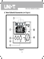
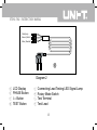
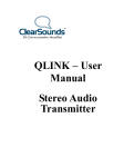
UT581/582
Digital RCD (ELCB)Tester
Instruction Manual
UT581/582 INSTRUCTION MANUAL
CONTENTS
Chapter
Page
1.Safety Instruction
2
2.Characteristics
6
3.General Specifications
8
4.Product Outlook & Accessories
12
5.Measurement Operation
14
6.Maintenance & Repair
18
1
UT581/582 INSTRUCTION MANUAL
1. Safety Instructions
This operation manual includes the user guidance and safety instruction
when using the tester, please read it before using.
Caution
● Before using the tester, please read and understand the operating
manual including the content.
● Keep the operating manual properly, and let it easy to get it for
reference during the process of testing.
● When using the tester, user must follow the testing procedure as
mentioned in the operating manual.
● Careful reading the operating manual regarding the safety information
and it is content.
● Must be followed all the related safety instructions, otherwise it may
cause accidents or damage the tester.
2
UT581/582 INSTRUCTION MANUAL
Safety sign“
”has three meaning in this manual, user has to pay the
attention to this sign“
”for operation.
Danger---identifies conditions and actions that most likely
pose hazard(s) or die.
Warning---identifies conditions and actions that will pose
hazard(s) or die.
Caution---identifies conditions and actions that will pose
hazard(s) or damage the tester.
Danger
● This test instrument unit is suitable for using under single phase
230V+10%-15%.(Operational Voltage Scope: 195 – 253 V)
● To avoid possible electric shock or personal inquiry. Do not use the
test instrument or test leads if they appear damaged or metal part is
exposed, or if test instrument is not operating properly. If in doubt,
please contact the instrument serviced.
3
UT581/582 INSTRUCTION MANUAL
● Do not use your finger to touch on any testing cable during the testing
stage.
● Put off the test leads after testing complete. P.S. test leads can not
always plugs on the test instrument.
Warning
● Do not open or disassemble the tester un-intentionally during the
measurement, it has a high voltage inside and cause a danger for the
user. If it needs service repairing, please contact our after-sales
services or our agents.
● If the test instrument appear abnormal ( for example, no completed
display, incorrect calculation, housing damage, noise issue during
the measurement etc….). please contact our after-sales services or
our agents.
● Do not use the tester if your hands are in wet.
4
UT581/582 INSTRUCTION MANUAL
Caution
● Ensure the test lead probe (need to be provided by UNI-TREND
Certified One) insert into the corresponding port in order to provide a
safe before measurement. It is not encourage to use third parties test
lead probe on our tester.
● Do not expose the tester in extreme temperature and wet environment.
● Soft cloth and mild detergent should be used to clean the surface of
the tester. No abrasive and solvent should be used when servicing.
● Dry the tester before storing if it is wet.
This Tester has the follow signs,please pay attention to the content when
using
Identifies danger, warning, caution
Identifies double or reinforced insulation
Grounding
CE conforms to Standards of European Union
5
UT581/582 INSTRUCTION MANUAL
2. Characteristics
2.0 This tester is suitable for using under single phase 230 V / 50 Hz.
(Operational Voltage Scope: 195 – 253 V)
2.1 It uses micro-controller with high accuracy, reliability and satiability.
2.2 Connectivity Checking: 3-LED Lamp signal is correct or not .
Correct connectivity: P-E & P-N display
two green light signal on but red light is off, If
not, you may incorrect to connect it.
2.3 Phrase Switch Selection: Can select positive (0°) or negative (180°)
semi-cycle commencing testing.
2.4 Over-range display“OL”indication. “OL mS” signal will be displayed on
LCD under the time limitation of the testing condition of over the time
limit.
2.5 Auto-data hold: Data hold for a while after each testing transaction.
2.6 Fast Trip Fixed: Current250mA (MAX: 40mS)(UT581 only).
2.7 AUTO RAMP Test: AUTO RAMP can test the trip test and trop current
6
UT581/582 INSTRUCTION MANUAL
in sync(UT582 only).
2.8 Power Off Buzzer: Buzzer alarm after turn off 3 minutes.
2.9 Environmental Protection Energy Conservation: This tester can not
use Battery operation, it can use cable to charge on under(under A/C
220V/50Hz only).
2.10 Fuse: Fused safety protection directly.
2.11 Double insulation or reinforced insulation safety manufacturing.
7
UT581/582 INSTRUCTION MANUAL
3. General Specifications
3.1 Measuring range & Tolerance. (Temperature: 23±5℃; Humidity:
45%~75% RH; Elevation below ≤2000 meter)
UT581:
Functions Voltage(AC)
X 1/2
X1
230V
(Tolerance:
-15%~+10%)
Frequency:
50Hz
Accuracy
Trip Time
(MAX)
Trip Current Trip Time
Trip Current
Setting (I△n)
10 / 20 / 30 /100 /
300 / 500mA
1000mS
10 / 20 / 30 /100 /
300 mA
1000mS
500mA
X5
10 / 20 / 30mA
300mS
1000mS
250mA
(Fast
Trip)
250mA(Fixed)
40 mS
8
Tolerance:
-10%~0%
Tolerance:
0%~+ 10%
Tolerance:
0%~+ 10%
±0.6% rdg
±4dgt
UT581/582 INSTRUCTION MANUAL
UT582:
Functions Voltage(AC)
X 1/2
X1
X5
AUTO
RAMP
TEST
Trip Current
Setting (I△n)
Trip Time
(MAX)
10 / 20 / 30 /100 /
300 / 500mA
230V
(Tolerance: 10 / 20 / 30 /100 /
-15%~+10%) 300 mA
Frequency:
500mA
50Hz
10 / 20 / 30mA
Accuracy
Trip Current Trip Time
1000mS
Tolerance:
-10%~0%
1000mS
±0.6% rdg
Tolerance: ±4dgt
0%~+ 10%
300mS
1000mS
(RAMP
Tolerance:
10 / 20 / 30 /100 increase to
-10%~+10%
/ 300 / 500mA
10%) I△n from
20%~110%
300*10 mS
9
UT581/582 INSTRUCTION MANUAL
3.2 Measuring Range (Functions)
×1/2
as disconnecting measurement, test RCD
sensitive.
×1
as connecting measurement of the response
time.
×5
as fast connecting measurement of I△n×5
time.
250mA
as connecting measurement of the response
time. (UT581 only)
AUTO RAMP TEST
as connecting measurement of the size of
the current. (UT582 only)
3.3 Application Standard:
IEC 61010-1 CAT III 300V Polluting Grade: Grade II
IEC 61557-1,5
IEC 61010-2-31
3.4 Operational Voltage: 230VAC/50Hz (Voltage Range: 195 – 253 V)
10
UT581/582 INSTRUCTION MANUAL
3.5 Working Environment: Temperature: 0℃~40℃
Relative Humidity: ≤80%RH
Elevation: ≤2000 meter
3.6 Storage Condition:
Temperature: -20℃~60℃
Relative Humidity: ≤75%RH
3.7 Product Size: 160mmx70.5mmx100mm
3.8 Product Net Weight: About 500g
3.9 Standard Accessories:
Test Leads(1.5 meter)
1 piece
English Mnaual
1 piece
Carrying Case
1 set
11
UT581/582 INSTRUCTION MANUAL
4. Tester Outlook & Accessories (see Diagram)
Diagram 1
12
UT581/582 INSTRUCTION MANUAL
Red (Live)
Green ( Earth )
Blue ( Neutral )
Diagram 2
①
②
③
④
LCD Display
PHASE Button
I△n Button
TEST Button
⑤
⑥
⑦
⑧
Connecting Lead Testing LED Signal Lamp
Rotary Mode Switch
Test Terminal
Test Lead
13
UT581/582 INSTRUCTION MANUAL
5. Measurements
5.1 Test Lead Connection
Test terminal is / are for connecting the correct lead of the tested
installation: L to L(Live); N to N(Neutral); E to E(Earthing).
5.2 Test Lead Checking
After connected the test leads with the testers, please plug the power
cable on (220V/50Hz current socket), so you can 3-LED lamp
whether it is correct. If P-E & P-N are displayed green signal light, but
the red color LED do not light up. It is in good normal condition. If
not, it may be incorrectly connect with P and N. You need to put off
those test leads and check it then plug into the correct one.
Connecting inadequately terminal P & terminal N during the measurement
it may cause to have a leakage.
Caution:Please check all the relative terminal and settle down it, you
can continue the next measurement.
14
UT581/582 INSTRUCTION MANUAL
Danger
● If the connecting measurement is incorrect, please don’t proceed the
next measurement (press TEST button). Otherwise, it causes
measuring result incorrect or in other dangerous.
5.3 Press I△n button switch, it causes RCD breakers for the nominal
residual currents (I△n) as the previous trip current in constant
Below LCD display the default connecting current value.
Default Value: I△n
30mA
0°/180°
0°
5.4 Measuring Methods
5.4.1Setting Index For Measurement
• Disconnecting Test
×1/2: Maximum Measuring Time 1000ms
• Connecting Test
×1: Maximum Measuring Time 1000ms
( Except 500mA)
• Connecting Test
×1 (500mA): Maximum Measuring Time
300ms
15
UT581/582 INSTRUCTION MANUAL
• Rapid Connecting Test
×5 (10,20,30mA only): Maximum
Measuring Time 1000ms
• Rapid Connecting Test
250 mA: Maximum Measuring
Time1000ms(UT581 only)
• AUTO RAMP TEST
Auto Ramp Test(UT582 only).
20%~110% Default nominal residual
currents(I△n).
Maximum measuring time 300ms×10.
5.4.2 Press TEST(Measure)button
• Disconnecting Test
Breaker should not be connected.
•Connecting Test
Breaker should be connected.
•Fast Connecting Test
Breaker should be connected.
•250mA Fast Test
Breaker should be connected.
(UT581 only)
•AUTO RAMP TEST
Breaker should be connected; can
display the connected current and time
in sync. (UT582 only)
16
UT581/582 INSTRUCTION MANUAL
5.4.3 Press PHASE (0°/180°) button, phase switch as repeated Step
(5.4.2 ) to get the fast connecting time.
5.4.4 Need to phase switch and repeated the Step (5.4.2).
Warning
● Do not use the tester if it is damaged or metal part is exposed.
● During the long hours and continually use, the tester may arise in
more heating and cause to the unit damage or / and other danger
arises, so we do not encourge to use in long hours and it is used on
sample random testing purpose only.
● Connecting current 300mA / 500 mA (Main current connecting
measurement) measure need to have at least 5-minutes variation for
next new measurement.
17
UT581/582 INSTRUCTION MANUAL
6. Maintenance & Repair
6.1 Soft cloth and mild detergent should be used to clean the surface of
the tester because solvent will corrosive the display and avoid
moisture.
6.2 Repair
Contact our after-sales service department or agent when the
following thing happens:
A.The tester case is being damage or broken.
B.LCD display is in abnormal.
C.Unreasonable deviation when in normal use.
D.Buttons do not function properly and confusion.
E.Sound during the testing.
This operating manual is subject to change without notice
18
UT581/582 INSTRUCTION MANUAL
19