1
ScanMaster for Scanner Configuration
For 1 Series Barcode Scanners:
1070, 1500, 1502 (1D, tethered)
1560, 1562, 1660, 1661 (1D, cordless)
1504, 1704 (2D, tethered)
1564, 1664 (2D, cordless)
Version 1.30
Copyright © 2008~2011 CIPHERLAB CO., LTD.
All rights reserved
The software contains proprietary information of CIPHERLAB CO., LTD.; it is provided
under a license agreement containing restrictions on use and disclosure and is also
protected by copyright law. Reverse engineering of the software is prohibited.
Due to continued product development this information may change without notice. The
information and intellectual property contained herein is confidential between CIPHERLAB
and the client and remains the exclusive property of CIPHERLAB CO., LTD. If you find
any problems in the documentation, please report them to us in writing. CIPHERLAB
does not warrant that this document is error-free.
No part of this publication may be reproduced, stored in a retrieval system, or
transmitted in any form or by any means, electronic, mechanical, photocopying,
recording or otherwise without the prior written permission of CIPHERLAB CO., LTD.
For product consultancy and technical support, please contact your local sales
representative. Also, you may visit our web site for more information.
The CipherLab logo is a registered trademark of CIPHERLAB CO., LTD.
All brand, product and service, and trademark names are the property of their registered
owners.
The editorial use of these names is for identification as well as to the benefit of the
owners, with no intention of infringement.
CIPHERLAB CO., LTD.
Website: http://www.cipherlab.com
RELEASE NOTES
Version
Date
Notes
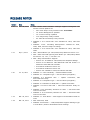
1.30
Dec. 08, 2011
1.21
1.20
Sep. 7, 2011
Jul. 13, 2011
New model 1664 included. Changes applied throughout the
manual. Critical updates are:
o
“RTC Time Setup” newly inserted under Tools Menu
o
1.2 “Power Management” updated
o
1.2.2 “Power-Saving” updated
o
1.14 “Pager Beep” newly inserted
o
5.3 “Date & Time Stamp” newly inserted
Modified: 1.13.1 “Fixed Gain” isn’t available for 1504, 1564 and
1664.
Modified: 1.13.2: “Decoding Autoexposure” enabled for 1504,
1564, 1664, and isn’t subject to change.
Modified: 1.13.2 “Fixed Gain” isn’t available for 1504, 1564 and
1664.
New: “Picklist Mode” (for 1504/1564/1704) added for section 1.11.
New: “Kanji Transmission” Support:
New: “Auto Power Off Ignoring Scan Mode” (for 1560/1564) added
for sections 1.2, 1.2.1, 1.2.2 and 1.2.3.
o
Section 2.1.10 added for 1504/1564/1704 Keyboard Wedge
o
Section 2.4.9 added for 1564 Bluetooth HID and section 2.7
added for 1564 USB HID via 3656.
o
Screenshot modified in section 2.7.
o
Screenshot modified in section 2.9.
o
Section 2.9.4 added for 1504/1704 Direct USB HID.
Modified: 1.1.4 Re-read Delay — add Presentation Mode
Modified: 2.4.1 Keyboard Type — add #77 PCAT (Hungarian)
Modified: 2.9.3 Secondary Interface for 1661 — add Send Data
Time-out for 1661
Modified: 2.10.3 Secondary Interface for 1661 — add Send Data
Time-out for 1661
Modified: 2.1.1 Keyboard Type — add #31 PCAT (Hungarian)
Modified: 2.4 Bluetooth
Inter-Character Delay
HID
—
update
screenshot,
add
Modified: 2.7 USB HID via 3656/3610 — update screenshot
Modified: 2.9 Direct USB HID — add Inter-Character Delay for
1070
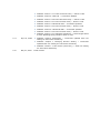
1.19
Mar. 04, 2011
Modified: 1.1 Scan Mode — add support of Presentation Mode for
1704
1.18
Mar. 02, 2011
New: add 1504, 1564
Modified: Introduction — 1560/1562/1660 supports Settings Type
in Tools Menu | Read or Download scanner settings
1.17
1.16
1.15
1.14
Jan. 10, 2011
Nov. 29, 2010
Sep. 29, 2010
May 12, 2010
New: add 1070
Modified: 1.8.2 Send Data & Clear Memory (Secondary Interface
for 1661)
New: 2.9.2 Manual Switch of Interface for 1070
Modified: 5.2.4 Examples — add Pause, update screenshots
Modified: 1.2 Power Management (1560/1562/1660) — add
Bluetooth SPP Master Mode for 1560/1562
Modified: 1.7 Auto Sense (1500/1560) — updated
Modified: 2.4.2 Keyboard Settings — add “Alphabets Layout” for
Bluetooth HID and USB HID
New: 2.6 Bluetooth SPP Master Mode — supports 1560/1562
Modified: Introduction — 1661 supports Settings Type in Tools
Menu | Read or Download scanner settings
New: 2.9.3 Secondary Interface for 1661
New: 2.10.2 Manual Switch of Interface for 1070
New: 2.10.3 Secondary Interface for 1661
New: 2.11 Direct USB CDC Virtual COM
Modified: 3.10 GS1-128 (EAN-128) — Decode behavior
New: add 1661
New: Introduction — add System Requirements
Modified: 1.2 Power Management — supports 1661
Modified: 1.2.3 Low Battery Alarm — supports 1661
Modified: 1.8 Memory Mode — supports 1661
Modified: 1.10 Transmit Buffer — supports 1661
New: add 1502
New: 2.9 Direct USB HID
New: 2.10 Direct USB Virtual COM
Modified: 3.16 GS1 DataBar (RSS Family)
Modified: 5.2.2 Field Settings — add Pause Field Time
Modified: 5.2.3 Transmission Sequence — add Pause, update
screenshot
Support 1704
Modified: Download Menu changed to Tools Menu and add “2D
Image Processing”
New: 1.11 More Settings (1704)
New: 1.12 2D Decode Settings (1704)
Modified: 2.1.1 Keyboard Type — add Turkish
Modified: 2.4.1 Keyboard Type — add Turkish for Bluetooth HID
and USB HID
New: Appendix I 2D Image Processing
1.13
Feb. 04, 2010
1.12
Jul. 31, 2009
1.11
Jul. 07, 2009
1.10
1.05
1.04
1.03
1.02
Modified: 1.2 Power Management (1560/1562/1660) — add
Bluetooth SPP Master Mode for 1660
Modified: 2.4.1 Keyboard Type — add Turkish for 1660, Bluetooth
HID and USB HID
New: 2.4.7 Character Transmit Mode
Modified: 1.2.1 Auto Power Off
New: 2.6 Bluetooth SPP Master Mode (1660 Only)
Modified: 3 Changing Symbology Settings — update screenshot
Modified: 3.9 EAN-13 — add Security Level
Modified: 3.11 ISBT 128 — ISBT 128 enabled by default
Modified: 4.1 Length Code — update screenshot
Modified: 4.4 Code ID — update screenshot
Modified: 4.5 Code Length — update screenshot
Modified: 4.7 Remove Special Character — update screenshot
Modified: 5.2.1 Applicable Conditions — update screenshot
1560/1562 supports keyboard wedge and RS-232 via 3656
New: 1.2 Power Management
(1560/1562/1660)
—
add
Power-Saving
setting
2.4.4 Authentication
2.5.1 Authentication
Apr. 21, 2009
Support 1560/1562
New: 1.10 Transmit Buffer (1560/1562/1660)
Mar. 02, 2009
Modified: 5.2.1 Applicable Conditions — Data length includes
prefix, suffix, length code, etc.
Modified: Scanner Information — screenshot updated with new
setting for Good Read LED duration
Modified: Chapter 1 Changing Scanner Setting — screenshot
updated with new setting for Good Read LED duration
Modified: section 1.3.3 Good Read LED — adds new setting for
Good Read LED duration
Modified: section 2.1 Keyboard Wedge — screenshot updated
Feb. 11, 2009
Dec. 19, 2008
Nov. 14, 2008
New: 2.6 USB HID (1560/1562/1660)
New: 2.7 USB Virtual COM (1560/1562/1660)
New: 4.6 Remove Special Character
Modified: 3.10 GS1-128 (EAN-128)
Modified: 3.16 GS1 DataBar (RSS Family)
Modified: 1.1 Scan Modes — add Alternate Mode
Modified: 1.1.4 Re-read Delay — add Alternate Mode
Modified: 4.6 Multi-Barcode Editor — 4-digit length excludes prefix,
suffix, length code, etc.
Modified: section 2.1.10 Inter-Character Delay — allows 0~254
1.01
1.00
Sep. 16, 2008
May 27, 2008
Modified: section 2.1.11 Inter-Function Delay — allows 0~254
Modified: Scanner Information — screenshot updated with new
setting for Auto-Sense Sensitivity
Modified: Chapter 1 Changing Scanner Setting — screenshot
updated with new setting for Auto-Sense Sensitivity
Modified: section 1.7 Auto Sense (1500 Only) — adds new setting
for Auto-Sense Sensitivity
Modified: section 2.2 RS-232 — screenshot updated
Modified: section 2.2.6 Inter-Character Delay — allows 0~254
Modified: section 2.2.7 Inter-Function Delay — allows 0~254
Modified: section 2.4 Bluetooth HID — screenshot updated
Modified: section 2.4.3 Inter-Function Delay — allows 0~254
Modified: section 2.5 Bluetooth SPP — screenshot updated
Modified: section 2.5.4 Inter-Function Delay — allows 0~254
Modified: section 5.2.1 Applicable Conditions — Data Length allows
0~254; Matching String Location allows 0~254
Initial release
CONTENTS
RELEASE NOTES .............................................................................................................................. - 3 INTRODUCTION .................................................................................................................................... 1
System Requirements ....................................................................................................................... 2
Using ScanMaster .............................................................................................................................3
How to Configure the Scanner?................................................................................................... 4
Setup Barcodes ............................................................................................................................ 6
Scanner Information ....................................................................................................................8
Menu Bar............................................................................................................................................9
File Menu ...................................................................................................................................... 9
Configure Menu ..........................................................................................................................10
Tools Menu .................................................................................................................................11
Help Menu...................................................................................................................................13
Toolbar .............................................................................................................................................14
CHANGING SCANNER SETTINGS .......................................................................................................15
1.1 Scan Mode ................................................................................................................................17
1.1.1 Scanning Timeout.............................................................................................................19
1.1.2 Continuous Mode Decode Delay .....................................................................................19
1.1.3 Aiming Timeout .................................................................................................................19
1.1.4 Re-read Delay ...................................................................................................................20
1.1.5 Read Redundancy ............................................................................................................20
1.1.6 Addon Security for UPC/EAN ...........................................................................................20
1.2 Power Management (1560/1562/1564/1660/1661/1664) .............................................21
1.2.1 Before/After Bluetooth Connection.................................................................................21
1.2.2 Power-Saving ....................................................................................................................22
1.2.3 Auto Power Off ..................................................................................................................23
1.2.4 Auto Power off Ignoring Scan Mode (1560/1564) ........................................................23
1.2.5 Low Battery Alarm ............................................................................................................23
1.3 Status Indicator.........................................................................................................................24
1.3.1 Beeper Volume .................................................................................................................24
1.3.2 Good Read Beep...............................................................................................................24
1.3.3 Good Read LED.................................................................................................................24
1.4 "No Read" Support (Send "NR" to Host) ..................................................................................24
1.5 Read Negative Barcode............................................................................................................24
1.6 CCD Always Active (1560 Only) ................................................................................................24
1.7 Auto Sense (1500/1560/1564) .............................................................................................25
1.8 Memory Mode (1560/1562/1564/1660/1661/1664).......................................................26
1.8.1 Data Delay.........................................................................................................................26
1.8.2 Send Data & Clear Memory .............................................................................................26
1.9 Effective Decoding Area ...........................................................................................................27
1.10 Transmit Buffer (1560/1562/1564/1660/1661/1664) ..................................................28
1.11 Picklist Mode (1504/1564/1664/1704) ............................................................................29
1.12 More Settings (1664/1704)..................................................................................................29
ScanMaster User Guide
1.13 2D Decode Settings (1704) ...................................................................................................29
1.13.1 Image Mode....................................................................................................................30
1.13.2 Decode Mode .................................................................................................................32
1.13.3 Video Mode.....................................................................................................................35
1.14 Pager Beep (1664) .................................................................................................................36
1.14.1 Windows-based PC.........................................................................................................36
1.14.2 Smart Handheld .............................................................................................................37
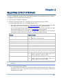
SELECTING OUTPUT INTERFACE .......................................................................................................39
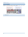
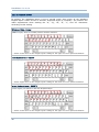
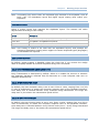
2.1 Keyboard Wedge.......................................................................................................................41
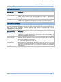
2.1.1 Keyboard Type ..................................................................................................................42
2.1.2 Alternate Composing ........................................................................................................42
2.1.3 Alphabets Transmission...................................................................................................43
2.1.4 Digits Transmission ..........................................................................................................44
2.1.5 Capital Lock Type..............................................................................................................45
2.1.6 Capital Lock State ............................................................................................................45
2.1.7 Alphabets Layout ..............................................................................................................46
2.1.8 Digits Layout .....................................................................................................................47
2.1.9 Laptop Support .................................................................................................................47
2.1.10 Kanji Transmission (1504/1564/1704)......................................................................47
2.1.11 Inter-Character Delay .....................................................................................................47
2.1.12 Inter-Function Delay.......................................................................................................47
2.1.12 Sniff Mode (via 3656)....................................................................................................48
2.1.13 Cable Auto-Detec (1504/1704)....................................................................................48
2.2 RS-232.......................................................................................................................................49
2.2.1 Baud Rate .........................................................................................................................50
2.2.2 Data Bits ...........................................................................................................................50
2.2.3 Parity .................................................................................................................................50
2.2.4 Stop Bit..............................................................................................................................50
2.2.5 Flow Control ......................................................................................................................50
2.2.6 Inter-Character Delay .......................................................................................................50
2.2.7 Inter-Function Delay .........................................................................................................50
2.2.8 ACK/NAK Timeout ............................................................................................................51
2.2.9 Sniff Mode (via 3656) ......................................................................................................51
2.2.10 Cable Auto-Detec (1504/1704)....................................................................................51
2.3 Wand Emulation........................................................................................................................52
2.3.1 Margin Time ......................................................................................................................53
2.3.2 Module Time .....................................................................................................................53
2.3.3 Normal State.....................................................................................................................53
2.3.4 Bar State ...........................................................................................................................53
2.4 Bluetooth HID............................................................................................................................54
2.4.1 Keyboard Type ..................................................................................................................55
2.4.2 Keyboard Settings ............................................................................................................55
2.4.3 Character Transmit Mode ................................................................................................56
2.4.4 Inter-Character Delay .......................................................................................................56
2.4.5 Inter-Function Delay .........................................................................................................56
2.4.6 Authentication ..................................................................................................................57
2.4.7 Broadcasting.....................................................................................................................58
2.4.8 Sniff Mode.........................................................................................................................58
2.4.9 Kanji Transmission (1564) ..............................................................................................58
2.5 Bluetooth SPP Slave Mode.......................................................................................................59
2.5.1 Authentication ..................................................................................................................60
ScanMaster User Guide
2.5.2 Device Name Broadcasting .............................................................................................61
2.5.3 Sniff Mode.........................................................................................................................61
2.5.4 Inter-Function Delay .........................................................................................................61
2.5.5 ACK/NAK Timeout ............................................................................................................61
2.6 Bluetooth SPP Master Mode ....................................................................................................62
2.7 USB HID via 3656/3610..........................................................................................................64
2.8 USB Virtual COM via 3656/3610 ............................................................................................65
2.9 Direct USB HID ..........................................................................................................................66
2.9.1 Cable Auto-Detec for 1504/1704...................................................................................67
2.9.2 Manual Switch of Interface for 1070 ..............................................................................67
2.9.3 Secondary Interface for 1661/1664 ..............................................................................67
2.9.4 Kanji Transmission for 1504/1704................................................................................67
2.10 Direct USB VCOM....................................................................................................................68
2.10.1 Cable Auto-Detec for 1504/1704.................................................................................69
2.10.2 Manual Switch of Interface for 1070............................................................................69
2.10.3 Secondary Interface for 1661/1664............................................................................69
2.11 Direct USB VCOM_CDC...........................................................................................................70
CHANGING SYMBOLOGY SETTINGS ..................................................................................................71
3.1 Codabar .....................................................................................................................................73
3.1.1 For 1D Scanners...............................................................................................................73
3.1.2 For 2D Scanners...............................................................................................................74
3.2 Code 25 — Industrial 25 ...........................................................................................................75
3.2.1 For 1D Scanners...............................................................................................................75
3.2.2 For 2D Scanners...............................................................................................................76
3.3 Code 25 — Interleaved 25........................................................................................................77
3.3.1 For 1D Scanners...............................................................................................................77
3.3.2 For 2D Scanners...............................................................................................................78
3.4 Code 25 — Matrix 25 ................................................................................................................79
3.4.1 For 1D Scanners...............................................................................................................79
3.4.2 For 2D Scanners...............................................................................................................80
3.5 Code 39 .....................................................................................................................................81
3.5.1 For 1D Scanners...............................................................................................................81
3.5.2 For 2D Scanners...............................................................................................................82
3.6 Code 93 .....................................................................................................................................84
3.6.1 For 1D Scanners...............................................................................................................84
3.6.2 For 2D Scanners...............................................................................................................84
3.7 Code 128...................................................................................................................................85
3.7.1 For 1D Scanners...............................................................................................................85
3.7.2 For 2D Scanners...............................................................................................................85
3.8 EAN-8 .........................................................................................................................................86
3.8.1 For 1D Scanners...............................................................................................................86
3.8.2 For 2D Scanners...............................................................................................................87
3.9 EAN-13.......................................................................................................................................88
3.9.1 For 1D Scanners...............................................................................................................88
3.9.2 For 2D Scanners...............................................................................................................89
3.10 GS1-128 (EAN-128)................................................................................................................90
3.10.1 For 1D Scanners ............................................................................................................90
ScanMaster User Guide
3.10.2 For 2D Scanners ............................................................................................................91
3.11 ISBT 128 .................................................................................................................................92
3.11.1 For 1D Scanners ............................................................................................................92
3.11.2 For 2D Scanners ............................................................................................................92
3.12 MSI ..........................................................................................................................................93
3.12.1 For 1D Scanners ............................................................................................................93
3.12.2 For 2D Scanners ............................................................................................................94
3.13 French Pharmacode ...............................................................................................................95
3.13.1 For 1D Scanners ............................................................................................................95
3.13.2 For 2D Scanners ............................................................................................................95
3.14 Italian Pharmacode ................................................................................................................96
3.14.1 For 1D Scanners ............................................................................................................96
3.14.2 For 2D Scanners ............................................................................................................96
3.15 Plessey ....................................................................................................................................97
3.15.1 For 1D Scanners ............................................................................................................97
3.15.2 For 2D Scanners ............................................................................................................97
3.16 GS1 DataBar (RSS Family).....................................................................................................98
3.16.1 For 1D Scanners ............................................................................................................99
3.16.2 For 2D Scanners ......................................................................................................... 101
3.17 Telepen................................................................................................................................. 103
3.17.1 For 1D Scanners ......................................................................................................... 103
3.17.2 For 2D Scanners ......................................................................................................... 103
3.18 UPC-A .................................................................................................................................... 104
3.18.1 For 1D Scanners ......................................................................................................... 104
3.18.2 For 2D Scanners ......................................................................................................... 105
3.19 UPC-E.................................................................................................................................... 106
3.19.1 For 1D Scanners ......................................................................................................... 106
3.19.2 For 2D Scanners ......................................................................................................... 107
3.20 1D More (1504/1564/1664/1704) ................................................................................. 108
3.20.1 Chinese 25 .................................................................................................................. 108
3.20.2 Trioptic Code 39 .......................................................................................................... 108
3.20.3 Code 11 ....................................................................................................................... 109
3.20.4 Coupon Code ............................................................................................................... 110
3.20.5 Composite Code .......................................................................................................... 111
3.20.6 Postal Code.................................................................................................................. 112
3.21 2D Symbologies (1504/1564/1664/1704)..................................................................... 113
DEFINING OUTPUT FORMAT ........................................................................................................... 115
4.1 Letter Case ............................................................................................................................. 116
4.2 Character Substitution........................................................................................................... 117
4.2.1 Applicable Code Types .................................................................................................. 118
4.3 Prefix/Suffix Code .................................................................................................................. 119
4.4 Code ID ................................................................................................................................... 120
4.4.1 Code ID Set 1~5 ............................................................................................................ 121
4.4.2 Change Code ID ............................................................................................................. 122
4.4.3 Clear ............................................................................................................................... 122
4.5 Code Length ........................................................................................................................... 123
4.6 Output Sequence (Multi-Barcode Editor) ............................................................................. 124
ScanMaster User Guide
4.7 Remove Special Character.................................................................................................... 126
APPLYING EDITING FORMATS ........................................................................................................ 127
5.1 Format Selection.................................................................................................................... 128
5.1.1 Enable Editing Formats ................................................................................................. 128
5.1.2 Exclusive Data Editing ................................................................................................... 128
5.2 Configure Editing Format....................................................................................................... 129
5.2.1 Applicable Conditions.................................................................................................... 129
5.2.2 Field Settings ................................................................................................................. 131
5.2.3 Transmission Sequence................................................................................................ 133
5.2.4 Examples........................................................................................................................ 134
5.3 Date & Time Stamp (1664) ................................................................................................... 136
Options ..................................................................................................................................... 136
More Button ............................................................................................................................. 137
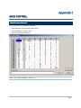
GRID CONTROL ............................................................................................................................... 139
Original Grid Control ..................................................................................................................... 139
Special Grid Control for Keyboard Interface ............................................................................... 140
Grid Control — Normal Key...................................................................................................... 140
Grid Control — Scan Code ....................................................................................................... 141
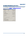
2D IMAGE PROCESSING (1704 ONLY)........................................................................................... 143
Transmission Properties .............................................................................................................. 144
Receive Mode .......................................................................................................................... 144
COM Port Setting ..................................................................................................................... 144
Save to File.................................................................................................................................... 145
Auto File Name ............................................................................................................................. 145
Image Capture & Signature ......................................................................................................... 145
Start 2D Image Processing .......................................................................................................... 146
Retrieving an Image ................................................................................................................ 146
Retrieving a Video.................................................................................................................... 147
Retrieving a Signature............................................................................................................. 148
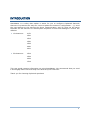
INTRODUCTION
ScanMaster is a utility that makes it easier for you to configure CipherLab Barcode
Scanners. It presents two ways for users to update the scanner’s configuration – (1) send
the new settings to the scanners by direct communication, and (2) print out the setup
barcodes for the scanners to read anytime anywhere to load new settings or recover the
defaults.
1D Scanners:
1070
1500
1502
1560
1562
1660
1661
2D Scanners:
1504
1564
1664
1704
This user guide contains information on using ScanMaster. We recommend that you read
it thoroughly before use and keep it at hand for quick reference.
Thank you for choosing CipherLab products!
1
ScanMaster User Guide
SYSTEM REQUIREMENTS
To run the ScanMaster, one of the Windows operating systems is required:
2
Windows 2000
Windows XP
Windows Vista
Windows 7
Introduction
USING SCANMASTER
The ScanMaster is installed with a folder that contains two programs, ScanMaster.exe
and PrintBarcode.exe. They function for the configuration of the scanners. First, run
ScanMaster.exe on your computer. Select the model you are going to configure, and its
configuration can be done by (A) starting a new configuration, (B) opening an existing
configuration file, or (C) reading the configuration from a scanner. Then send the
configuration to other scanners directly, or generate a file named Barcode.prn to keep a
copy of the setup barcodes for the configuration.
Refer to Chapter 4
Defining Output Format
Refer to Chapter 3
Changing Symbology Settings
Refer to Chapter 5
Applying Editing Formats
Refer to Chapter 2
Selecting Output Interface
Refer to Chapter 1
Changing Scanner Settings
Note: (1) When you choose to generate the setup barcodes, a file named Barcode.prn is
brought about inside the directory where the ScanMaster.exe and
PrintBarcode.exe co-exists. If you wish to keep the Barcode.prn file, you need to
rename it; otherwise it is overwritten each time a new set of setup barcodes is
generated again.
(2) The *.prn file is printable. Open a *.prn file with the PrintBarcode.exe.
3
ScanMaster User Guide
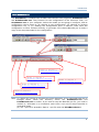
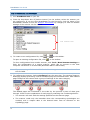
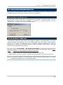
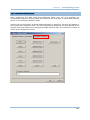
HOW TO CONFIGURE THE SCANNER?
1) Run ScanMaster.exe on your PC.
2) From the drop-down box of [Select Scanner] on the toolbar, select the scanner you
are configuring. If you are using ScanMaster for the first time, click the items in the
ScanMaster window to see the Scanner Information by category so that the default
settings of the scanner can be viewed.
The scanner info
3) To create a new configuration file, click
To open an existing configuration file, click
or
on the toolbar.
on the toolbar.
To clone configuration from another scanner, click Tools | Read Scanner Settings to
fetch the configuration of a source scanner, which has to connect to the host
computer via RS-232 or Virtual COM (Bluetooth SPP or USB VCOM).
Note: If you are using USB Virtual COM for the first time, you must install its driver from
the CD-ROM.
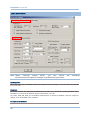
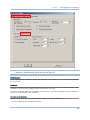
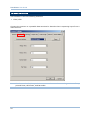
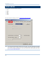
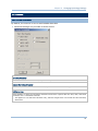
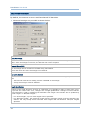
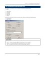
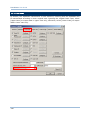
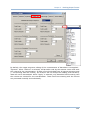
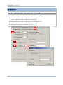
4) To configure the scanner. Select Configure from the menu bar. The window [Scanner
Settings] displays presenting a series of tabbed page as illustrated below. Each tabbed
page configures the scanner with a group of settings of the same category.
The tabbed pages are numbered in the order by the process a piece of data goes
through. Check out the explanation of each page by matching the numberings below:
1. The scanner will work with the settings specified on the Scanner page.
2. The scanner reads only the barcodes when the corresponding symbologies are
enabled, and it outputs data in the desired letter case as selected on the
Symbology page.
4
Introduction
3. The scanner checks one by one whether the read barcode meets the criteria for a
concatenation of barcodes as configured on the Output Sequence page.
4. The scanner performs character substitution as defined on the Format Editing
page.
5. The scanner adds a 2-digit length code to the desired symbologies as selected on
the Code Length page.
6. The scanner adds a 1- or 2-character identifier to the desired symbologies as
selected on the Code ID page.
7. The scanner applies editing formats to the desired symbologies that meet the
criteria as configured on the Format Editing page.
8. The scanner adds a prefix/suffix code to the enabled symbologies as selected on
the Symbology page.
9. Finally the scanner outputs data via the desired interface.
5) If the scanner is connected to the host computer via RS-232 or Virtual COM
(Bluetooth SPP or USB VCOM), you can directly download the settings; otherwise you
button on the menu bar to print out the setup barcodes to apply
need to click the
the settings to the scanner by reading setup barcodes.
Note: The program PrintBarcode.exe must be in the same folder of ScanMaster.
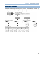
6) When the scanner is configured successfully, connect it to the host computer via a
proper interface: Keyboard wedge, RS-232, Wand Emulation, Bluetooth HID,
Bluetooth SPP, USB HID, or USB Virtual COM.
Note: If the scanner is set to the Wand Emulation mode, you need to connect it to a
portable data terminal or a decoder that is expecting input from a wand scanner.
5
ScanMaster User Guide
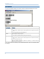
SETUP BARCODES
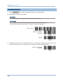
To recover the default settings, the scanner needs to read these barcodes one by one.
Setup Barcodes
Indication
Enter Setup
Scan this barcode to put the scanner into configuration mode. Upon scanning –
Restore
Settings
the scanner responds with six beeps (high-low tone repeats three times),
and
the LED indicator becomes flashing red
Default Scan this barcode to restore the scanner to default state. When the scanner
has successfully read the barcode –
Update
the scanner responds with two beeps (low-high tone)
Scan this barcode to confirm the updating –
the scanner responds with six beeps (high-low tone repeats three times),
and
the LED indicator goes off.
When the scanner successfully updates the settings, it restarts itself and
responds with one long beep.
If you want to load new settings, scan associated barcodes. Take the screenshot below
for example.
6
Introduction
You can always restore the default settings.
The setup barcodes are categorized into groups of related settings, such as Scanner
Settings, Prefix/Suffix Settings, Interface Settings, Code ID Settings, etc.
After making any change to the settings, you need to scan the "Update" barcodes to
confirm such change. However, if a decimal or hexadecimal value is involved in the
setting, you need to scan the "Validate" barcode prior to the "Update" barcode.
7
ScanMaster User Guide
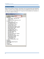
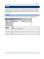
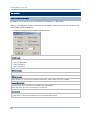
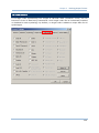
SCANNER INFORMATION
After a scanner model is selected, a drop-down tree will be presented in the ScanMaster
window. It enables user’s quickly view through the categorized information about the
scanner. Select one of the available themes to see the default settings of the scanner. If
you open an existing configuration file or change the current settings, the information in
this tree gets updated accordingly.
8
Introduction
MENU BAR
The menu bar contains a number of menus that cause the program to take actions. Each
menu contains a list of commands. Some of the options carry out commands immediately
while others display their windows to which you input information further. If a submenu is
labeled with an ellipsis [...], it displays a window that requires your further configuration
when it is selected; otherwise it deals with a command that causes an action to be carried
out immediately.
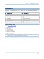
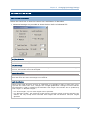
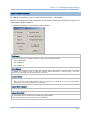
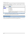
FILE MENU
The File Menu contains the commands that produce the actions as tabulated below:
Command
Action
New
To create a new configuration file.
Open
To open an existing configuration file. File path needs to be specified.
Save
To save the current settings.
Save As
To save the current settings to a new configuration file.
Exit
To close the ScanMaster program.
9
ScanMaster User Guide
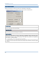
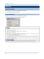
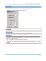
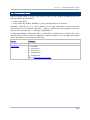
CONFIGURE MENU
The Configure Menu contains one command that displays the [Scanner Settings] dialog
box that accesses the settings as tabulated below:
Command
Action
Configure
Scanner
Configures the current settings for the target scanner.
Refer to the following sections –
10
Chapter 1 – Changing Scanner Settings
Chapter 2 – Selecting Output Interface
Chapter 3 – Changing Symbology Settings
Chapter 4 – Defining Output Format
Chapter 5 – Applying Editing Formats
Introduction
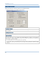
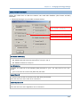
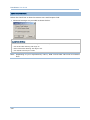
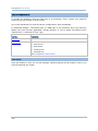
TOOLS MENU
The Tools Menu contains the submenus that launch the actions as tabulated below:
Command
Action
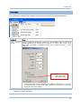
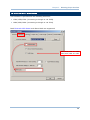
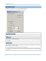
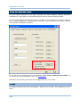
Read
Scanner Displays [COM Port Properties] dialog box that enables users to fetch the
Settings
settings applied on the scanner at the moment. For 1504, 1560, 1562, 1564,
1660, 1661 and 1664, it supports to fetch user’s defined settings (= “User
Defaults”).
For 1504
1560/1562/1564
1660/1661/1664
A dialog box pops up for configuring the COM port properties on your PC.
For Bluetooth SPP or USB Virtual COM, specify the COM port for connection
and ignore the other settings.
Note: To clone settings, first read settings from a specific scanner, and then send the
settings to other scanners.
11
ScanMaster User Guide
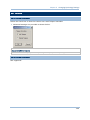
2D
Image
Processing
Refer to 1.13 2D Decode Settings (1704) and Appendix I — 2D Image
Processing (1704 Only).
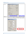
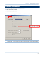
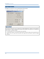
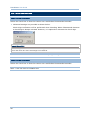
Download
Scanner Settings
Displays the [COM Port Properties] dialog box that enable users to send the
settings made in the ScanMaster to the target scanner when the scanner is
connected to your PC via RS-232 or Virtual COM (Bluetooth SPP or USB VCOM).
For 1504, 1560, 1562, 1564, 1660, 1661, and 1664, it supports sending the
settings to the scanner as “User Defaults”.
For 1504
1560/1562/1564
1660/1661/1664
12
Introduction
The [COM Port Properties] dialog box provides the access to set the COM
port properties on your PC. For Bluetooth SPP or USB Virtual COM, specify
COM port for connection and ignore the other settings.
Print
Scanner Runs PrintBarcode.exe to print out the Setup Barcodes based on the settings
Settings
made in the ScanMaster which are automatically saved in the Barcode.prn file.
If the scanner is not connected to the host computer via RS-232 or Virtual COM
(Bluetooth SPP or USB VCOM), scanner configuration can be changed by
scanning the setup barcodes.
RTC Time Setup
The setup barcodes are categorized into groups of related settings.
Sets clock / calendar time for the 1664 scanner to affix date/time stamps to
scanned barcodes. See also 5.3 Date & Time Stamp (1664).
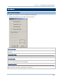
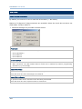
HELP MENU
The Help Menu contains the command “About ScanMaster”.
13
ScanMaster User Guide
Command
Action
About
ScanMaster
Provides the information about the version, copyright and developer of the
ScanMaster.
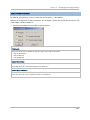
TOOLBAR
The toolbar enables the quick access to most of the commands with the following
buttons:
From left to right, the buttons invoke the following commands:
14
New
Open
Save
Configure
Print
Download Settings
Select among the scanners – 1070, 1500, 1502, 1504,
1560, 1562, 1564, 1660, 1661, 1664, 1704
Chapter 1
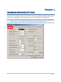
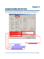
CHANGING SCANNER SETTINGS
The [Scanner Settings] dialog box features a number of tabbed property pages which
enable your configuration to the barcode scanner that optimizes your application.
Note: The options available slightly differ from model to model. For example, “Low
Battery Alarm” is provided for 1560/1562/1564/1660/1661/1664 only.
15
ScanMaster User Guide
IN THIS CHAPTER
1.1 Scan Mode ................................................................ 17
1.2 Power Management (1560/1562/1564/1660/1661/1664). 21
1.3 Status Indicator ......................................................... 24
1.4 "No Read" Support (Send "NR" to Host) ........................ 24
1.5 Read Negative Barcode ............................................... 24
1.6 CCD Always Active (1560 Only).................................... 24
1.7 Auto Sense (1500/1560/1564)..................................... 25
1.8 Memory Mode (1560/1562/1564/1660/1661/1664) ........ 25
1.9 Effective Decoding Area .............................................. 27
1.10 Transmit Buffer (1560/1562/1564/1660/1661/1664) .... 28
1.11 Picklist Mode (1504/1564/1664/1704)......................... 29
1.12 More Settings ......................................................... 29
1.13 2D Decode Settings (1704)........................................ 29
1.14 Pager Beep (1664) .................................................. 36
16
Chapter 1
Changing Scanner Settings
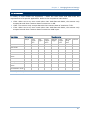
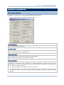
1.1 SCAN MODE
A variety of scan modes are supported – select the scan mode that best suits the
requirements of a specific application. Refer to the comparison table below.
1504: When set to any scan mode other than Multi-Barcode Mode, the scanner only
accepts barcode that contains data of maximum 10 KB.
1564: The scanner only accepts barcode that contains data of maximum 7 KB.
1704: When set to any scan mode other than Multi-Barcode Mode, the scanner only
accepts barcode that contains data of maximum 4084 bytes.
Start to Scan
Scan Mode
Always
Press
trigger
once
Stop Scanning
Hold
trigger
Press
trigger
twice
Release
trigger
Press
trigger
once
Barcode Timeout
being
read
Continuous mode
Test mode
Laser mode
Auto Off mode
Auto Power
mode
Off
Alternate mode
Aiming mode
Multi-Barcode
mode
Presentation mode
Note: By default, the scan mode is set to Laser mode.
17
ScanMaster User Guide
Continuous Mode
The scanner is always scanning.
To decode the same barcode repeatedly, shift the scan beam away and target on the barcode
for each scanning.
Note: Refer to “Decode Delay” and “Delay between Re-read”.
Test Mode
The scanner is always scanning.
Capable of decoding the same barcode repeatedly, for testing purpose.
Laser Mode
The scanning is activated as long as the trigger is pulled down.
The scanning won't get deactivate until (1) a barcode is decoded, (2) the pre-set timeout
expires, or (3) you release the trigger.
Note: Refer to “Scanning Timeout”.
Auto Off Mode
The scanner will start scanning once the trigger is pressed.
The scanning won't stop until (1) a barcode is decoded, and (2) the pre-set timeout expires.
Note: Refer to “Scanning Timeout”.
Auto Power Off Mode
The scanner will start scanning once the trigger is pressed.
The scanning won't stop until the pre-set timeout expires, and, the pre-set timeout period
re-counts after each successful decoding.
Note: Refer to “Delay between Re-read” and “Scanning Timeout”.
Alternate Mode
The scanner will start scanning once the trigger is pressed.
The scanning won't stop until you press the trigger again.
Aiming Mode
The scanner will aim at a barcode once the trigger is pressed, and start scanning when the trigger
is pressed again within one second.
The scanning won't stop until (1) a barcode is decoded, (2) the pre-set timeout expires, or (3)
you release the trigger.
Note: Refer to “Aiming Timeout”.
18
Chapter 1
Changing Scanner Settings
Multi-Barcode Mode
The scanner will be scanning as long as the trigger is held down, capable of decoding one single
barcode, as well as a multiple unique barcodes one at a time. While decoding a bunch of unique
barcodes, if a barcode is decoded twice, its subsequent decoding will be ignored and the scanner
is expecting another unique barcode.
For the 2D scanners to decode multiple unique barcodes, the maximum output data length of all
the barcodes is 10 KB (1504/1564/1664) and 2042 bytes (1704) after configuration. When the
output length exceeds the maximum length allowed, Multi-Barcode Mode will not take effect.
The scanning won't stop until you release the trigger.
Note: (1) A barcode is considered unique when its Code Type or data is different from
others. (2) Multi-Barcode Mode has nothing to do with the Multi-Barcode Editor.
Presentation Mode (1504, 1564 and 1704 only)
The scanner will be expecting barcodes. Whenever a barcode is brought within range, the scanner
will be able to decode it. It is suggested to seat it in the Auto-Sense Stand for hands-free
operation.
1.1.1 SCANNING TIMEOUT
Specify the scanning time interval (1~254 sec.; 0= disable) when the scan mode is set to
any of the following scan mode –
Laser mode
Auto Off mode
Auto Power Off mode
Aiming mode
1.1.2 CONTINUOUS MODE DECODE DELAY
Set the time interval between each decoding when in Continuous Mode.
1.1.3 AIMING TIMEOUT
You can limit the aiming time interval (1~15 sec.) when in Aiming Mode. By default, the
scanner time-out is set to 1 second.
19
ScanMaster User Guide
1.1.4 RE-READ DELAY
This is also referred to as the “Blocking Time”, which is used to prevent the scanner from
accidentally reading the same barcode twice when the scan mode is set to any of the
following scan mode —
Continuous mode
Auto Power Off mode
Alternate mode
Presentation Mode
1.1.5 READ REDUNDANCY
Select the level of reading security. For example,
If "No Redundancy" is selected, one successful decoding will make the reading valid
and induce the "READER Event".
If "Three Times" is selected, it will take a total of four consecutive successful
decodings of the same barcode to make the reading valid. The higher the reading
security is (that is, the more redundancy the user selects), the slower the reading
speed gets.
It is obvious that the more redundancy you select, the higher the reading security is, and
thus, the slower the reading speed becomes. You will have to compromise between
reading security and decoding speed.
1.1.6 ADDON SECURITY FOR UPC/EAN
This option is available on the Symbology property tab. You may like to enforce
redundant reading (1~30 times; 0= disable) on UPC/EAN barcodes with addons only.
Note: UPC/EAN Addon 2 and Addon 5 must be enabled individually for this setting to take
effect.
20
Chapter 1
Changing Scanner Settings
1.2 POWER MANAGEMENT (1560/1562/1564/1660/1661/1664)
The Bluetooth-enabled models such as 1560, 1562, 1564, 1660, 1661, and 1664 feature
the management of power consumption. Such management enables the scanner to
control its power state in response to the input from the user. By the scanner’s power
management, the power consumption goes through the following transition:
1) The scanner stays active with full CPU speed right after power-on.
2) The scanner shifts to low CPU speed. (“Power-Saving”. See 1.2.2 Power-Saving)
3) The scanner finally shuts down. (“Auto Power Off”. See 1.2.3 Auto Power Off & 1.2.4
Auto Power off Ignoring Scan Mode (1560/1564).
Note there are a few eccentric cases:
The “Power-Saving” is inoperative for the Bluetooth HID or SPP on all concerned
models except for 1664. The 1664 is able to deliver Power-Saving for Bluetooth HID
and SPP.
For the 1661 and 1664 set to Direct USB for output, the “Power-Saving” and “Auto
Power Off” only comes to service when the USB cable gets loosened or connects
improperly.
1.2.1 BEFORE/AFTER BLUETOOTH CONNECTION
Before and after the Bluetooth connection is made, the scanner features similar power
managing mechanism. The following details how it is achieved.
Before establishing a WPAN connection successfully…
1.
The scanner stays active for a time (2 minutes by default) attempting either of the following.
The CPU runs at full speed, and the LED blinks blue (On/Off ratio 0.5 s: 0.5 s).
(a) waiting for a connection request from the host (Bluetooth SPP Slave Mode)
(b) trying to connect to the host (Bluetooth HID or Bluetooth SPP Master Mode)
(c) trying to connect to 3656 or 3610
Note in the cases of (a) and (b), you may need to search for the scanner again on your
computer.
2.
If the scanner fails to connect throughout the active time (2 minutes by default), the CPU
slows down and the scanner becomes inactive to save power. The LED starts to blink red
(On/Off ratio 0.3 s: 2.5 s).
Pull the scan trigger or press the scan button to resume the scanner.
3.
Failing to make connection, the scanner shifts to inactive state when it is the time (the
Power-Saving time). Then scanner keeps inactive and finally turns off to conserve battery
power when it is the time (the Auto Power Off time).
Pull & hold the scan trigger or press & hold the [Power/Delete] button to turn the scanner
back on.
21
ScanMaster User Guide
After establishing a WPAN connection successfully…
1.
Once a WPAN connection is established successfully, the scanner stays active for a time (2
minutes by default) for data transmission. The CPU runs at full speed, and the LED blinks blue
(On/Off ratio 0.02 s: 3 s).
2.
If the scanner is left idle throughout the active time (2 minutes by default), the scanner shifts
to inactive state to save power. The CPU runs at low speed, and the LED blinks red (On/Off
ratio 0.3 s: 2.5 s).
Press and hold the [Trigger] button to recover the scanner’s activity.
3.
There is no transition from full CPU speed to low CPU speed for Bluetooth HID and SPP,
however when the connection is based on a 3656 or 3610, the scanner will go through a
low CPU speed stage in order to save power.
1664 is an exception from the said behavior. The 1664 goes through low CPU speed to
save power for Bluetooth HID and SPP
Being left idle, the scanner shifts to inactive state when it is the time (the Power-saving time).
Then the scanner keeps inactive and finally turns off with three short beeps, tone descending
from high to low, when it is the time (the Auto Power Off time).
Press & hold the [Power/Delete] button to turn the scanner back on. When the scanner
re-powers on, it attempts reconnecting to the host:
For Bluetooth HID, the scanner resumes connection with the host upon powering on again
as long as the host application is still running. You will hear three short beeps, tone
ascending from low to high. If the scanner fails to resume the connection, it tries every 5
seconds unless the scanner reads the “Reset Connection” barcode.
For Bluetooth SPP Slave Mode, the scanner must wait for the host to re-connect.
Interfacing with 3656 or 3610, the scanner tries re-connecting to 3656 or 3610 unless you
turn off the scanner.
For Bluetooth SPP Master Mode, the scanner resumes the connection with the host upon
powering on again as long as the host application is running. You will hear three short
beeps, tone ascending from low to high. If the scanner fails to resume the connection, it
tries every 5 seconds unless the scanner read the “Reset Connection” or “Restore System
Defaults” barcode.
1.2.2 POWER-SAVING
“Power-Saving” is provided for all scan modes. Set up a time (1~254 min.; 0= disable)
after power-on for the scanner to enter low-speed mode to save power. By default, the
scanner keeps active for 2 minutes after power-on and before entering low-speed
power-saving.
Note either of the following cases will set the Power-Saving inefficacious:
1) the interface is Bluetooth HID or SPP
(the 1664 is an exception to feature Power-Saving as usual),
2) the scan mode is set to Test, Continuous or Alternate Mode,
3) 1560/1564 is in Auto-Sense mode and seated in the Auto-Sense Stand, or
4) the setting value of Power-Saving is greater than that of Auto Power Off.
22
Chapter 1
Changing Scanner Settings
1.2.3 AUTO POWER OFF
The setup of an “Auto Power Off” time is available to any scan mode other than
Continuous Mode, Test Mode and Alternate Mode.
Select “Auto Power Off” and assign a time (1~254 min.; 0= disable) for the scanner that
is set to none of the above mentioned modes to automatically shut down after power-on.
The default value is set to 10 minutes, which means the scanner automatically shuts
down 10 minutes after power-on by default.
Note: For 1560 and 1564, when they are set to Auto-Sense mode and seated in the
Auto-Sense Stand, “Auto Power Off” won’t work.
1.2.4 AUTO POWER OFF IGNORING SCAN MODE (1560/1564)
“Auto Power Off Ignoring Scan Mode” is provided for Continuous Mode, Test Mode and
Alternate Mode only.
Select “Auto Power Off Ignoring Scan Mode” and assign a time (1~254 min.; 0= disable)
to force a scanner set to any of the above mentioned modes to automatically shut down
at the assigned time after power-on.
The default value is set to 10 minutes, which means the scanner automatically shuts
down 10 minutes after power-on by default.
1.2.5 LOW BATTERY ALARM
By default, the low battery alarm is enabled. When the battery level drops below a
specified level, the scanner will respond with a warning beep.
For 1660, “Enable (Alkaline)” is selected for low battery level by default. If you are
using Ni-MH batteries, select “Enable (Ni-MH)”.
23
ScanMaster User Guide
1.3 STATUS INDICATOR
For 1704, refer to 1.12 More Settings for Good Read Vibrator.
1.3.1 BEEPER VOLUME
Beeping functions to alert users of various states of the scanner, such as Good Read,
buffer full status, configuration status, etc. Select a suitable volume.
1.3.2 GOOD READ BEEP
Good Read Beep is always enabled. By default, beeper frequency is set to 4 KHz and
duration is set to shortest. Select a different frequency and duration if necessary.
1.3.3 GOOD READ LED
By default, Good Read LED is enabled and its duration is set to 40 milliseconds. When
reading a barcode successfully, the LED on the scanner will become solid green and go off
quickly. Enter a value ranging from 1 to 254, in units of 10 milliseconds.
1.4 "NO READ" SUPPORT (SEND "NR" TO HOST)
The scanner will send the “NR” string to the host to notify the No Read event.
1.5 READ NEGATIVE BARCODE
Normally, barcodes are printed with the color of the bars darker than that of the spaces.
However, for negative barcodes, they are printed in the opposite sense just like negative
films. The spaces of negative barcodes are printed with a color darker than that of the
bars. You can configure the scanner to be able to read negative barcodes.
1.6 CCD ALWAYS ACTIVE (1560 ONLY)
This feature intends to keep the CCD sensor always active so that the scanner can decode
more efficiently.
Note: For the 1500 scanner, the CCD sensor is set to “Always Active” and isn’t subject to
change.
24
Chapter 1
Changing Scanner Settings
1.7 AUTO SENSE (1500/1560/1564)
This mode is only applicable when you want to seat the 1500/1560/1564 scanner in the
Auto-Sense Stand. The scanner will be scanning as long as it is seated in the Auto-Sense
Stand, as shown below. Whenever a barcode is brought within the coverage, the scanner
will be able to decode it.
When the ambient light is too dim to activate the sensor, you may change the sensitivity
from “Normal” to “High” to improve performance of 1500/1560.
Warning:
When you disable this mode later, proceed to select a scan mode best suits
your application.
Note: For Auto-Sense mode to work for 1560/1564, you must connect (1) the power
supply cord and (2) the interface cable to the Auto-Sense Stand.
25
ScanMaster User Guide
1.8 MEMORY MODE (1560/1562/1564/1660/1661/1664)
Memory mode is disabled by default. When the scanner is in memory mode, it means any
connection established with host is disabled.
The scanner keeps flash memory for memory mode operation.
1560/1562/1661:512 KB
1564/1664:
4 MB
1660:
256 KB
Warning:
No connection is allowed unless the memory mode is disabled.
1.8.1 DATA DELAY
You may set a delay between each data record while transmitting data back to the
server.
1.8.2 SEND DATA & CLEAR MEMORY
When flash memory is run out, the scanner will respond with two short beeps (high-low
tone) as a warning. You are advised to send data to the server immediately by having the
scanner read the setup barcodes. Refer to a separate manual.
For 1560/1562/1564/1660/1664, the scanner will resume the previous WPAN
connection with the host computer temporarily.
For 1661 and 1664, the scanner can send data via “Direct USB” interface when the
cable is connected. Otherwise, it will resume the previous WPAN connection with the
host computer temporarily. When you connect the cable in Memory Mode, the scanner
is set to the output interface of “Direct USB Virtual COM” by default. Refer to 2.9.3
Secondary Interface for 1661.
Unless you erase the memory by having the scanner read two setup barcodes – “Clear
Data” and “Confirm”, the flash memory won’t be cleared up even if the data is sent to the
host computer.
26
Chapter 1
Changing Scanner Settings
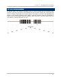
1.9 EFFECTIVE DECODING AREA
In default state, the effective decoding area is 100% covered by the scanned area.
However, you may narrow down the decoding area to prevent reading the wrong barcode
when a number of barcodes are printed closely. The scanner will only read barcodes that
appear in the effective decoding area. Select “Centering Window” and the percentage to
narrow down the decoding area. For example, read “Left 10%” and then “Right 30%” for
the scanner to decode barcode “A” only.
27
ScanMaster User Guide
1.10 TRANSMIT BUFFER (1560/1562/1564/1660/1661/1664)
By default, transmit buffer is enabled and ready for use when the scanner is carried out
of the effective Bluetooth range. Upon reading a barcode successfully within the effective
range, the scanner responds with one short beep (high tone) and its LED indicator
becomes solid green and goes off quickly. However, the host computer may not receive
the data immediately if getting out of the effective range.
For 1560/1562 with 4 KB transmit buffer, the scanner can ignore the transmission
status and keep on reading barcodes until the buffer is full.
For 1564 and 1664 with 10 KB transmit buffer, the scanner can ignore the
transmission status and keep on reading barcodes until the buffer is full.
For 1660/1661 with 1 KB transmit buffer, the scanner can ignore the transmission
status and keep on reading barcodes until the buffer is full.
When transmit buffer is enabled…
When the scanner is carried out of Bluetooth coverage, it will respond with two short beeps,
high-low tone, upon reading a barcode successfully.
When transmit buffer is full, the scanner will respond with one long beep (low tone) and its LED
indicator will become solid red and go off quickly. You are advised to back in the coverage.
When transmit buffer is disabled…
When the scanner is carried out of the coverage, it will respond with one long beep (low tone) and
its LED indicator will become solid red and go off quickly. You are advised to back in the coverage.
28
Chapter 1
Changing Scanner Settings
1.11 PICKLIST MODE (1504/1564/1664/1704)
Picklist Mode is deselected by default. Select it to enable the scanner to decode only the
barcodes aligned at the centre under the laser aiming pattern.
1.12 MORE SETTINGS (1664/1704)
For 1664 and 1704, the scanner is equipped with a vibrator. You may enable it for the
annunciator of Good Read. When enabled, it vibrates for 1 second. Specify a value,
ranging from 1 to 254 in units of 100 milliseconds.
1.13 2D DECODE SETTINGS (1704)
1704 supports different scan modes and signature capture in Decode Mode. Two more
operation modes are supported, which are Image Mode and Video Mode. Image capture
occurs in all modes of operation, and it requires software applications, such as
ScanMaster, to capture and download images to PC for decoding. Please refer to separate
manual for OCX programming support.
For 1704, go to Tools Menu | 2D Image Processing to start with the retrieval of
signature, image or video. Both active and passive modes are supported. Refer to Tools
Menu and Appendix I — 2D Image Processing (1704 Only).
Active Mode: Control the scanner from the software on the host.
Passive Mode: Have the scanner read the setup barcodes for the desired operation.
Note: For signature capture in Decode Mode, Image Mode and Video Mode, the output
interface must be RS-232 or USB Virtual COM.
29
ScanMaster User Guide
1.13.1 IMAGE MODE
Note: When
selecting
Image
Mode,
you
can
ignore
Illumination/Auto-exposure settings in [Preferences] group box.
the
Decoding
Fixed Exposure
When autoexposure is disabled, specify the exposure time (2~5000), in unit of 100 µs. By default,
it is set to 100.
Fixed Gain
For 1704, deselect the “Decoding Autoexposure” to make the “Fixed Gain” setting available. Once
available, it is set to 50 by default. Assign a value from 1 to 100.
For 1504, 1564 and 1664, the “Decoding Autoexposure” is selected (enabled), and isn’t subject to
change. The “Fixed Gain” isn’t available.
Illumination Bank Control
30
Chapter 1
Changing Scanner Settings
This is used to control the illumination banks on the scan engine. Options are –
Full: Enables the full illumination system.
Auto: Switches the illumination from left to right bank.
Left: Enables the left bank, which is on the left when facing the scan window.
Right: Enables the right bank, which is on the right when facing the scan window.
Note: When the ambient light is too dim on the left (or right), you may enable the left
(or right) illumination bank to add lighting.
Image Capture Illumination
Decide whether to cause the decoder to flash illumination on every image capture to aid decoding.
Enabling illumination usually results in superior images. The effectiveness of the illumination
decreases as the distance to the target increases.
Image Capture Autoexposure
Decide whether to manually specify the gain and exposure time (only recommended for advanced
users with difficult image capture situations). By default, exposure value is set to 10 ms and gain
value is set to 50 when autoexposure is disabled.
Bits per Pixel
Select the number of significant bits per pixel (BPP) to use when capturing an image. Select 1 BPP
for a black and white image, 4 BPP to assign 1 of 16 levels of grey to each pixel, or 8 BPP to
assign 1 of 256 levels of grey to each pixel. By default, it is set to 8 BPP. The decoder ignores
these settings for JPEG files, which always use 8 BPP.
Resolution
This feature alters image resolution before compression. Multiple pixels are combined to one pixel,
resulting in a smaller image containing the original content with reduced resolution.
Options for 1704:
Full: 1280 x 1024
(uncropped image size)
1/2: 640 x 512
(uncropped image size)
1/4: 320 x 160
(uncropped image size)
Enhancement
This feature uses a combination of edge sharpening and contrast enhancement to produce an
image that is visually pleasing.
File Format
Select an image format for storing captured images. By default, it is set to JPEG.
Brightness (Target White)
Decide whether to set the Target White value (1~240) when using autoexposure. White and black
are defined as 255 decimal and 0, respectively. If the value is 180, which is the factory default,
the white level of the image is ~180.
Aiming Pattern
Decide whether to allow the decoder to project the aiming pattern in Image Mode.
31
ScanMaster User Guide
Timeout
Set the amount of time the decoder remains in Image Mode. The decoder exits Image Mode upon
a trigger event, or when the Image Mode Timeout elapses. By default, the time-out value is set to
30 seconds.
Gain/Exposure Priority
Alter the decoder’s gain/exposure priority when it acquires an image in Image Mode with auto
exposure enabled.
Low Gain Priority: The decoder favors longer exposure time rather than higher gain to capture
an image. This ensures that the image is less noisy and produces fewer artifacts during
post-processing activities like image enhancement (sharpening). This mode is ideal for fixed
mount/fixed object image capture since the image acquired is susceptible to motion blur.
Low Exposure Priority: The decoder favors higher gain over exposure to capture an image.
This results in an image that is less susceptible to motion blur at the expense of noise
artifacts. However, for most applications, the amount of noise is acceptable.
Preview before Image Capture
Decide whether to enable Image Mode with View Finder, which the decoder behaves as a video
camera until a trigger event is activated.
Select the number of 100-byte blocks. Values range from 800 to 3000 bytes. Selecting a
smaller value transmits more frames per second; selecting a larger value increases video
quality. By default, it is set to 1700 bytes.
JPEG Image Options
Optimize JPEG images for either size or quality.
JPEG Target File Size: Specify the target JPEG file size in terms of 1 Kilobytes (1024 bytes). By
default, it is set to 160 Kilobytes
JPEG Quality: Specify the JPEG quality value (5~100). By default, it is set to 65.
Crop to Pixel Address
This is used to crop a captured image to the pixel addresses specified. When no cropping, it
presents the full 1280 x 1024 pixels for 1704.
For image cropping on 1704, set the pixel addresses from (0,0) to (1279, 1023) to crop to.
Columns are numbered from 0 to 1279, rows from 0 to 1023. Specify four values for Top, Left,
Bottom, and Right, where Top and Bottom correspond to row pixel addresses, and Left and
Right correspond to column pixel addresses. For example, for a 4 row x 8 column image in the
extreme bottom-right section of the image, set the following values:
Top = 1020, Bottom = 1023, Left = 1272, Right = 1279
Note: The scanner has a cropping resolution of 4 pixels. Setting the cropping area to less
than 3 pixels transfers the entire image.
1.13.2 DECODE MODE
By default, this is the normal operation mode. The decoder attempts to locate and decode
any barcode within its field of view upon a trigger event. Refer to 1.1 Scan Mode.
32
Chapter 1
Changing Scanner Settings
Note: When selecting Decode Mode, the Image Capture Illumination/Auto-exposure
settings in [Preferences] group box can be ignored.
Fixed Exposure
When autoexposure is disabled, specify the exposure time (2~5000), in unit of 100 µs. By default,
it is set to 100.
Fixed Gain
For 1704, deselect the “Decoding Autoexposure” to make the “Fixed Gain” setting available. Once
available, it is set to 50 by default. Assign a value from 1 to 100.
For 1504, 1564 and 1664, the “Decoding Autoexposure” is selected (enabled), and isn’t subject to
change. The “Fixed Gain” isn’t available.
Illumination Bank Control
This is used to control the illumination banks on the scan engine. Options are –
Full: Enables the full illumination system.
33
ScanMaster User Guide
Auto: Switches the illumination from left to right bank.
Left: Enables the left bank, which is on the left when facing the scan window.
Right: Enables the right bank, which is on the right when facing the scan window.
Note: When the ambient light is too dim on the left (or right), you may enable the left
(or right) illumination bank to add lighting.
Decoding Illumination
Decide whether to cause the decoder to flash illumination on every image capture to aid decoding.
Enabling illumination usually results in superior images. The effectiveness of the illumination
decreases as the distance to the target increases.
Decoding Autoexposure
Decide whether to manually specify the gain and exposure time (only recommended for advanced
users with difficult image capture situations). By default, exposure value is set to 10 ms and gain
value is set to 50 when autoexposure is disabled.
For 1504, 1564, and 1664, Decoding Autoexposure is selected (enabled) and isn’t subject to
change.
Fuzzy 1D Processing
By default, this option optimizes decode performance on 1D barcodes, including damaged and
poor quality barcodes. Disable this only if you experience time delays when decoding 2D barcodes,
or in detecting a no decode.
Aiming Pattern
Decide whether to allow the decoder to project the aiming pattern during a barcode capture.
Signature Capture
A signature capture barcode is a special-purpose symbology, which delineate a signature capture
area in a document with a machine-readable format. The recognition pattern is variable so it can
optionally provide an index to various signatures. The region inside the barcode pattern is
considered the signature capture area.
Go to Tools Menu | 2D Image Processing to allow the decoder to capture signature in Decode
Mode. Refer to Tools Menu.
Width (1~640) & Height (1~480): The aspect ratio of the Signature Capture Width and
Signature Capture Height parameters must match that of the signature capture area. For
example a 4 x 1 inch signature capture area would require a 4 to 1 aspect ratio of width to
height. By default, it is set to 400 and 100 respectively.
File Format: Select an image format for storing captured signatures. By default, it is set to
JPEG.
Bits per Pixel: Select the number of significant bits per pixel (BPP) to use when capturing a
signature. Select 1 BPP for a black and white image, 4 BPP to assign 1 of 16 levels of grey to
each pixel, or 8 BPP to assign 1 of 256 levels of grey to each pixel. By default, it is set to 8
BPP. The decoder ignores these settings for JPEG files, which always use 8 BPP.
JPEG Quality: Specify the JPEG quality value (5~100). By default, it is set to 65.
34
Chapter 1
Changing Scanner Settings
1.13.3 VIDEO MODE
Target Video Frame Size
Select the number of 100-byte blocks to transmit per second. Values range from 800 to 3300
bytes. Selecting a smaller value transmits more frames per second but reduces video quality;
selecting a larger value increases video quality but slows transmission. By default, it is set to 2200
bytes.
35
ScanMaster User Guide
1.14 PAGER BEEP (1664)
This function helps track down the 1664 scanner should it be misplaced or fall out of sight.
The Pager Beep relies on a host computer such as your Windows-based PC, smartphone,
or tablet to initiate some Bluetooth-based action to make the lost property beep so it
becomes noticeable.
In default state, the Pager Beep parameter is set to 5, which means Pager Beep is
enabled and between each beep are five seconds.
In the Pager Beep Duration spin box, set a number between 0 and 15. “0” will disable the
Pager Beep while the other numbers set the second(s) between each beep. (0~15
configurable, 0=disable)
The following describes what to do on different host computers to trace the 1664
scanner:
1.14.1 WINDOWS-BASED PC
When the host is a Windows-based PC, the transmission interfaces supported are
Bluetooth HID and Bluetooth SPP. Deviated from other 1-series Bluetooth-based models,
the 1664 scanner is able to deliver Power-Saving service for Bluetooth HID and SPP.
However the Pager Beep only comes to the rescue when the 1664 sits in low-speed
Power-Saving mode (see 1.2.2 Power-Saving). Hence a well provided Auto-Power Off
time is necessary for the Pager Beep to work because it isn’t possible once the scanner
powers off. (See also 1.2.3 Auto Power Off.)
The following describes what to do to locate the scanner for different interfaces:
BLUETOOTH HID
When it is the Bluetooth HID that interfaces the 1664 scanner, press either “Scroll Lock”,
“Num Lock”, or “Caps Lock” on the PC’s keyboard to revive the scanner afar. The scanner
will respond with 2 short beeps on a regular time basis (every 5 seconds by default) and
won’t stop until either of the following happens:
1) The scan button or power button is pressed.
2) It is the defined time for Power-Saving again. (The scanner returns to power-saving.)
Note: Only Windows PC’s keyboards are supported currently.
BLUETOOTH SPP
When it is the Bluetooth SPP that interfaces the 1664 scanner, initiate any
Bluetooth-based data transmission on the host computer by way of serial ports. The
scanner will recover the activity and respond with 2 short beeps on a regular time basis
(every 5 seconds by default) and won’t stop until either of the following happens:
1) The scan button or the power button is pressed.
36
Chapter 1
Changing Scanner Settings
2) It is the defined time for Power-Saving again. (The scanner returns to power-saving.)
1.14.2 SMART HANDHELD
Whether it is a smartphone or an ultra portable tablet PC, as long as it is paired and stays
connected with the lost 1664, either disconnection or reconnection from your smart
handheld will reactivate the scanner afar. The scanner will respond with 2 short beeps on
a regular time basis (every 5 seconds by default) and won’t stop until either of the
following happens:
1) The scan button or the power button is pressed.
2) It is the defined time for Power-Saving again. (The scanner returns to power-saving.)
Note it has to be the scanner’s last Bluetooth-connected device to be able to resume the
scanner through disconnection/reconnection.
37
ScanMaster User Guide
38
Chapter 2
SELECTING OUTPUT INTERFACE
In order to establish a proper wired connection between your computer and the scanner,
we suggest that you follow these instructions –
1) Turn off your computer or laptop.
2) Connect the scanner and your computer with the provided interface cable.
If using the RS-232 cable, join the power supply cord.
If you are connecting the scanner to the USB port of the host computer via USB
HID cable (part # 307), refer to 2.1 Keyboard Wedge for related settings.
If you are connecting the scanner to the USB port of the host computer via USB
Virtual COM cable (part # 308), refer to 2.2 RS-232 related settings.
If you are connecting the scanner to the IBM POS 4683/4694 via the converter
cable (part # 346), refer to 2.1 Keyboard Wedge for related settings.
Scanner
Output Interface
1070
(1)
Keyboard Wedge if using the "Y-shaped" cable
(2)
USB HID if using USB cable
1500/1502
Default: Keyboard Wedge
1560/1562/1564
Default: Bluetooth HID
1660/1661/1664
Default: Bluetooth HID
1504
Capable of detecting the interface
1704
Capable of detecting the interface
1560/1562 via 3656
Default: USB HID
1660 via 3610
Default: USB HID
1661 via 3610
(1)
Default: USB HID
(2)
Default: Direct USB Virtual COM if using the
“Direct” USB cable in Memory Mode
(1)
Default: USB HID
(2)
Default: Direct USB Virtual COM if using the
“Direct” USB cable in Memory Mode
1664 via 3610
Note: If a different interface is desired, change the interface setting and send it to the
scanner.
3) Turn on your computer or laptop.
For 1560/1562/1564 scanners, install the battery and hold down the trigger for 2
seconds to turn it on. They also support the output by the RS-232 or Keyboard
Wedge cable via 3656.
39
ScanMaster User Guide
For
1660/1661/1664 scanners,
[Power/Delete] key to turn it on.
install
batteries,
and
IN THIS CHAPTER
2.1 Keyboard Wedge........................................................ 41
2.2 RS-232..................................................................... 49
2.3 Wand Emulation ........................................................ 52
2.4 Bluetooth HID ........................................................... 54
2.5 Bluetooth SPP Slave Mode ........................................... 59
2.6 Bluetooth SPP Master Mode ......................................... 62
2.7 USB HID via 3656/3610 .............................................. 64
2.8 USB Virtual COM via 3656/3610 ................................... 65
2.9 Direct USB HID .......................................................... 66
2.10 Direct USB VCOM ..................................................... 68
2.11 Direct USB VCOM_CDC.............................................. 70
40
press
&
hold
the
Chapter 2
Selecting Output Interface
2.1 KEYBOARD WEDGE
This interface is for the following scanners:
1070/1500/1502/1504/1704
1560/1562/1564 (via 3656)
Use a “Y-shaped” keyboard wedge cable to connect between the scanners (models
1070/1500/1502/1504/1704 or 3656), the host computer, and the keyboard. The
scanned data will be transmitted to the host computer through the keyboard port as if it
is manually entered via the keyboard.
1560/1562/1564 via 3656
41
ScanMaster User Guide
2.1.1 KEYBOARD TYPE
By default, the keyboard type is set to PCAT (US). The following keyboard types are
supported –
No.
Keyboard Type
No.
Keyboard Type
1
PCAT (US)
16
PS55 001-2
2
PCAT (French)
17
PS55 001-82
3
PCAT (German)
18
PS55 001-3
4
PCAT (Italian)
19
PS55 001-8A
5
PCAT (Swedish)
20
PS55 002-1, 003-1
6
PCAT (Norwegian)
21
PS55 002-81, 003-81
7
PCAT (UK)
22
PS55 002-2, 003-2
8
PCAT (Belgium)
23
PS55 002-82, 003-82
9
PCAT (Spanish)
24
PS55 002-3, 003-3
10
PCAT (Portuguese)
25
PS55 002-8A, 003-8A
11
PS55 A01-1
26
IBM 3477 Type 4 (Japanese)
12
PS55 A01-2 (Japanese)
27
PS2-30
13
PS55 A01-3
28
IBM 34XX/319X, Memorex Telex 122 Keys
14
PS55 001-1
29
User-defined table
15
PS55 001-81
30
PCAT (Turkish)
31
PCAT (Hungarian)
2.1.2 ALTERNATE COMPOSING
By default, Alternate key composing is disabled. Select [Yes] to allow emulating Alternate
key code of a specific keyboard character. For example, [Alt] + [065] will be sent to host
for the character “A” regardless the keyboard type you are using.
42
Chapter 2
Selecting Output Interface
2.1.3 ALPHABETS TRANSMISSION
By default, the alphabets transmission is case-sensitive, which means the alphabets will
be transmitted according to their original case, the status of Caps Lock on the keyboard,
as well as the Capital Lock setting. Select [Ignore Case] to have alphabets transmitted
according to the status of Caps Lock on the keyboard only.
43
ScanMaster User Guide
2.1.4 DIGITS TRANSMISSION
By default, the alphanumeric keypad is used for transmitting digits. Select “Numeric
Keypad” if you wish to use the keys on the numeric keypad.
Note: If you select “Numeric Keypad”, the Num Lock status of the physical keyboard
should be "ON".
44
Chapter 2
Selecting Output Interface
2.1.5 CAPITAL LOCK TYPE
Cap Lock Type
Description
Normal
Normal type
Capital Lock
When enabled, the keys of alphabetic characters will be interpreted as
capital letters. However, this does not affect the number or punctuation
keys.
Shift Lock
When enabled, the keys of alphabetic characters will be interpreted as
capital letters. In addition, this affects the number or punctuation keys.
2.1.6 CAPITAL LOCK STATE
In order to send the alphabets with correct case, the scanner needs to know the status of
Caps Lock on the keyboard. Incorrect settings may result in reversed case of the
alphabets being transmitted.
Capital Lock State
Description
Capital Lock OFF
Assuming that the status of Caps Lock on the keyboard is OFF, transmitted
characters are exactly the same as in the barcode (when "case-sensitive" is
selected for Alphabets Transmission).
Capital Lock ON
Assuming that the status of Caps Lock on the keyboard is ON, transmitted
characters are exactly the same as in the barcode (when "case-sensitive" is
selected for Alphabets Transmission).
Auto Detection
Refer to the Capital Lock Type above.
The scanner will automatically detect the status of Caps Lock on the
keyboard before data is transmitted; transmitted characters are exactly the
same as in the barcode (when "case-sensitive" is selected for Alphabets
Transmission).
45
ScanMaster User Guide
2.1.7 ALPHABETS LAYOUT
By default, the alphabets layout is set to normal mode, also known as the standard
English layout. Select French or German keyboard layout if necessary. The scanner will
make adjustments when sending the "A", "Q", "W", "Z", "Y", and "M" characters
according to this setting.
US Keyboard Style – Normal
QWERTY layout, which is normally used in western countries.
Select “Lower Row” for the “Digits Layout” setting for the upper row is for special characters.
French Keyboard Style – AZERTY
French layout; see below for French Keyboard Style.
Select “Upper Row” for the “Digits Layout” setting for the lower row is for special characters.
German Keyboard Layout – QWERTZ
German layout; see below for German Keyboard Style.
46
Select “Lower Row” for the “Digits Layout” setting for the upper row is for special characters.
Chapter 2
Selecting Output Interface
Note: This setting only works when the keyboard type selected is US keyboard, such as
PCAT (US). The Alphabets Layout and Digits Layout setting must match your
keyboard.
2.1.8 DIGITS LAYOUT
Select a proper layout that matches the alphabets layout. The scanner will make
adjustments according to this setting.
Options
Description
Normal
Depends on the [Shift] key or [Shift Lock] setting
Lower Row
For QWERTY and QWERTZ keyboards
Upper Row
For AZERTY keyboards
Note: This setting is meant to be used with the Alphabets Layout, and perhaps the
Character Substitution setting when support to certain keyboard types (languages)
is unavailable but required.
2.1.9 LAPTOP SUPPORT
By default, laptop support is disabled. Select the check box if you connect the wedge
cable to a laptop without an external keyboard being inter-connected.
2.1.10 KANJI TRANSMISSION (1504/1564/1704)
Kanji Transmission is deselected by default. Select it to enable the scanner to transmit
the Japanese characters collected from 2D barcodes to a host computer that runs on
Japanese Windows O.S.
2.1.11 INTER-CHARACTER DELAY
By default, the inter-character delay is set to zero. Enter a value, ranging from 0 to 254
in units of millisecond, to match the computer response time of the keyboard interface.
Such delay time is inserted between every character being transmitted. The longer the
delay time is, the slower the transmission speed will be.
2.1.12 INTER-FUNCTION DELAY
By default, the inter-function delay is set to zero. Enter a value, ranging from 0 to 254 in
units of millisecond, to match the computer response time of the keyboard interface.
Such delay time is inserted between every function code (0x01 ~ 0x1F) being transmitted.
The longer the delay time is, the slower the transmission speed will be.
47
ScanMaster User Guide
2.1.12 SNIFF MODE (VIA 3656)
By default, this power-saving feature is enabled for 1560/1562/1564, meaning the
scanner will listen to the wireless network at a reduced rate while connecting via 3656.
2.1.13 CABLE AUTO-DETEC (1504/1704)
For 1504/1704, the scanner will detect the interface automatically. Find the interface
cable provided inside the package. Connect it to the scanner. Refer to Chapter 2 —
Selecting Output Interface.
Cable Auto-Detect
Defaults
Keyboard Wedge
PCAT (US) for keyboard type
RS-232
115200 bps, 8 bits, No parity, 1 stop bit
USB
USB HID and PCAT (US) for keyboard type
Note: If “USB Virtual COM” is desired, select it and download the setting to the scanner.
48
Chapter 2
Selecting Output Interface
2.2 RS-232
This interface is for the following scanners:
1500/1502/1504/1704
1560/1562/1564 (via 3656)
Connect 1500/1502/1504/1704 or 3656 to the serial port of the host computer using the
RS-232 cable and join the power adaptor to the RS-232 connector. The associated
RS-232 parameters must match those configured on the computer. The scanned data will
be transmitted to the serial port.
1560/1562/1564 via 3656
49
ScanMaster User Guide
2.2.1 BAUD RATE
By default, it is set 9600 bps for 1500/1502, but 115200bps for 1504/1704 and 3656.
Select other value that matches your computer settings.
2.2.2 DATA BITS
By default, it is set 8 bits of data. Select 7 bits of data if necessary.
2.2.3 PARITY
By default, it is set no parity bit. Select other parity setting, even or odd parity bit.
2.2.4 STOP BIT
By default, it is set 1 stop bit. Select 2 stop bits if necessary.
2.2.5 FLOW CONTROL
By default, there is no flow control in use. Select the flow control (handshake) method.
Options
Description
No
No flow control
Scanner Ready
The scanner will activate the RTS signal upon powering on. After each good
read, the scanner will then wait for the CTS signal to become active. Data
will not be sent until the CTS signal becomes active.
Data Ready
The RTS signal will be activated after each good read. The scanner will then
wait for the CTS signal to become active. Data will not be sent until the CTS
signal becomes active.
Inverted Data Ready
It works the same as the Data Ready flow control, except that the RTS
signal level is inverted.
2.2.6 INTER-CHARACTER DELAY
By default, the inter-character delay is set to zero. Enter a value, ranging from 0 to 254
in units of millisecond, to match the computer response time of the RS-232 interface.
Such delay time is inserted between every character being transmitted. The longer the
delay time is, the slower the transmission speed will be.
2.2.7 INTER-FUNCTION DELAY
By default, the inter-function delay is set to zero. Enter a value, ranging from 0 to 254 in
units of millisecond, to match the computer response time of the RS-232 interface. Such
delay time is inserted between every function code (0x01 ~ 0x1F) being transmitted. The
longer the delay time is, the slower the transmission speed will be.
50
Chapter 2
Selecting Output Interface
2.2.8 ACK/NAK TIMEOUT
By default, the scanner sends data to the host without waiting for an ACK/NAK response
before sending more data. Enter a value, ranging from 1 to 99 in units of 0.1 second. If
no response within the specified period of time, the scanner will attempt to send the
same data three more times. If all the attempts fail without any notification, data loss will
occur.
Note: We suggest that you enable the error beep so that you will be notified of such data
loss and have the scanner re-read data.
2.2.9 SNIFF MODE (VIA 3656)
By default, this power-saving feature is enabled for 1560/1562/1564, meaning the
scanner will listen to the wireless network at a reduced rate while connecting via 3656.
2.2.10 CABLE AUTO-DETEC (1504/1704)
For 1504/1704, the scanner will detect the interface automatically. Find the interface
cable provided inside the package. Connect it to the scanner. Refer to Chapter 2 —
Selecting Output Interface.
Cable Auto-Detect
Defaults
Keyboard Wedge
PCAT (US) for keyboard type
RS-232
115200 bps, 8 bits, No parity, 1 stop bit
USB
USB HID and PCAT (US) for keyboard type
Note: If “USB Virtual COM” is desired, select it and download the setting to the scanner.
51
ScanMaster User Guide
2.3 WAND EMULATION
This interface is for the following scanners:
1500/1502
Connect the scanner to a portable data terminal or decoder that is expecting input from a
wand scanner.
Note: Wands are handheld optical character readers used to read typewritten fonts,
printed fonts, OCR fonts, and barcodes.
52
Chapter 2
Selecting Output Interface
2.3.1 MARGIN TIME
By default, it is set 20 milliseconds as the time span for the change in state for bar and
space modules. Select other value for the margin time.
2.3.2 MODULE TIME
By default, it is set 1 millisecond as the time span for bar and space modules. Select
other value for the module time, in units of micro-second or millisecond.
2.3.3 NORMAL STATE
By default, the signal level is set "Low" for the normal state when not transmitting any
barcode.
2.3.4 BAR STATE
By default, the signal level is set "High" for a bar when transmitting a barcode. Select
"Low" for a bar if "High" for a space is desired.
53
ScanMaster User Guide
2.4 BLUETOOTH HID
This interface is provided for the following scanners:
1560/1562/1564 (connecting to dongle or via 3656)
1660/1661/1664 (connecting to dongle or via 3610)
In this mode, re-connection is made easy and reliable, just like connecting with 3610 (for
1660/1661/1664) or 3656 (for 1560/1562/1564). As a HID device, the scanner will
resume connection with the host upon powering on again, as long as the host application
is running. You will hear three short beeps, tone ascending from low to high. If the
scanner fails to resume connection, it will try every 5 seconds to re-connect to the host
unless you change the interface to Bluetooth SPP Slave and download settings to the
scanner.
Note: One alternative to stopping re-connection is to have the scanner read the “Reset
Connection” or “Restore System Defaults” barcode. Refer to a separate manual for
instructions.
1560/1562/1564 via 3656
1660/1661/1664 via 3610
54
Chapter 2
Selecting Output Interface
2.4.1 KEYBOARD TYPE
By default, the keyboard type is set to PCAT (US). The following keyboard types are
supported –
No.
Keyboard Type
No.
Keyboard Type
64
PCAT (US)
70
PCAT (UK)
65
PCAT (French)
71
PCAT (Belgium)
66
PCAT (German)
72
PCAT (Spanish)
67
PCAT (Italy)
73
PCAT (Portuguese)
68
PCAT (Swedish)
74
PS55 A01-2 (Japanese)
69
PCAT (Norwegian)
76
PCAT (Turkish)
77
PCAT (Hungarian)
2.4.2 KEYBOARD SETTINGS
Refer to 2.1 Keyboard Wedge.
Alphabets Layout
Digits Layout
Capital Lock Type
Capital Lock Setting
Alphabets Transmission
Digits Transmission
Note: Bluetooth HID does not support these functions on PDAs – (1) Capital Lock Setting:
Auto Detection (2) Digits Transmission: Numeric Key
55
ScanMaster User Guide
2.4.3 CHARACTER TRANSMIT MODE
By default, HID interface sends data to the host in batch. You may change it to process
data one character at a time.
2.4.4 INTER-CHARACTER DELAY
By default, the inter-character delay is set to zero. Enter a value, ranging from 0 to 254
in units of millisecond, to match the computer response time of the keyboard interface.
Such delay time is inserted between every character being transmitted. The longer the
delay time is, the slower the transmission speed will be.
2.4.5 INTER-FUNCTION DELAY
By default, the inter-function delay is set to zero. Enter a value, ranging from 0 to 254 in
units of millisecond, to match the computer response time of the RS-232 interface. Such
delay time is inserted between every function code (0x01 ~ 0x1F) being transmitted. The
longer the delay time is, the slower the transmission speed will be.
56
Chapter 2
Selecting Output Interface
2.4.6 AUTHENTICATION
When any changes are made to authentication and PIN code on the scanner side, you will
have to remove the scanner from the paired device list (called unpairing) and go through
the whole process to re-establish the connection.
The scanner allows up to 16 characters for a PIN code and provides two options for
authentication:
Enable Authentication with Preset PIN
Select the check box of “Authentication”, and enter exactly the same string in the “PIN Code” field
as the preset PIN for your computer or PDA to connect to the scanner. If the PIN or passkey is
incorrect, any connection attempt will be turned down by the scanner.
Enable Authentication with Random PIN or No Authentication
By default, it is set to “No PIN or use random PIN”, which depends on the setting of the target
device. (No PIN = No authentication.)
Use random PIN
No PIN required
57
ScanMaster User Guide
Note: When using Bluetooth HID, some device driver may not support pre-defined PIN
code for authentication. In this case, make sure you cancel the check box of
“Authentication” to have the scanner set to “No PIN or use random PIN” before
pairing. While pairing, the host PIN code will be displayed on the computer screen.
Have the scanner read the setup barcode “Enter PIN Code in Decimal” or “Enter
PIN Code in Hexadecimal” to input the matching PIN code.
2.4.7 BROADCASTING
The scanner can be configured to hide itself from other devices equipped with Bluetooth®
wireless technology. Simply disable the device name broadcasting setting so that it won’t
be discovered by any other computer or PDA. However, broadcasting must be enabled for
establishing an initial connection with the scanner.
For example, you can disable device name broadcasting after successfully connecting the
scanner to WorkStation1. Such connection will be maintained automatically unless the
scanner is removed from the paired device list (called unpairing) by WorkStation1 or any
changes made to authentication and the PIN code. If you want WorkStation2 to connect
to the scanner, you will have to enable device name broadcasting first.
Note: By default, device name broadcasting is enabled (which is required for initial
connection).
2.4.8 SNIFF MODE
By default, this power-saving feature is enabled for 1560/1562/1564/1660/1661/1664,
meaning the scanner will listen to the wireless network at a reduced rate.
Note: When connecting more than two scanners to a notebook computer or PDA with
Bluetooth® wireless technology, we suggest that you disable the power-saving
setting for a more reliable connection.
2.4.9 KANJI TRANSMISSION (1564)
Kanji Transmission is deselected by default. Select it to enable the scanner to transmit
the Japanese characters collected from 2D barcodes to a host computer that runs on
Japanese Windows O.S.
58
Chapter 2
Selecting Output Interface
2.5 BLUETOOTH SPP SLAVE MODE
This interface is provided for the following scanners:
1560/1562/1564 (connecting to dongle or via 3656)
1660/1661/1664 (connecting to dongle or via 3610)
Both Bluetooth SPP Master and Slave Mode are supported.
1560/1562/1564 via 3656
1660/1661/1664 via 3610
59
ScanMaster User Guide
2.5.1 AUTHENTICATION
When any changes are made to the authentication and PIN code on the scanner side, you
have to remove the scanner from the paired device list (called unpairing) and go through
the whole process to re-establish the connection. The scanner allows up to 16 characters
for a PIN code and provides two options for authentication:
Enable Authentication with Preset PIN
Select the check box of “Authentication”, and enter exactly the same string in the “PIN Code” field
as the preset PIN for your computer or PDA to connect to the scanner. If the PIN or passkey is
incorrect, any connection attempt will be turned down by the scanner.
Enable Authentication with Random PIN or No Authentication
By default, it is set to “No PIN or use random PIN”, which depends on the setting of the target
device. (No PIN = No authentication.)
Use random PIN
No PIN required
Note: For Bluetooth HID, some device driver may not support pre-defined PIN code for
authentication. In this case, make sure you cancel the check box of
“Authentication” to have the scanner set to “No PIN or use random PIN” before
pairing. While pairing, the host PIN code will display on the computer screen. Have
the scanner read the setup barcode “Enter PIN Code in Decimal” or “Enter PIN
Code in Hexadecimal” to input the matching PIN code.
60
Chapter 2
Selecting Output Interface
2.5.2 DEVICE NAME BROADCASTING
Device Name Broadcasting is selected by default. Deselect it to hide the scanner from
other Bluetooth®-enabled devices such as PC or PDA. However, broadcasting must be
enabled for establishing an initial connection with other Bluetooth®-enabled devices.
For example, you can disable device name broadcasting after successfully connecting the
scanner to WorkStation1. Such connection will be maintained automatically unless the
scanner is removed from the paired device list (called unpairing) by WorkStation1 or any
changes made to authentication and the PIN code. If you want WorkStation2 to connect
to the scanner, you have to enable device name broadcasting first.
Note: Device Name Broadcasting is selected by default (as it is required for initial
connection).
2.5.3 SNIFF MODE
This power-saving feature is selected by default for 1560/1562/1564/1660/1661/1664,
meaning the scanner will listen to the wireless network at a reduced rate.
Note: When connecting more than two scanners to a notebook computer or PDA with
Bluetooth® wireless technology, we suggest that you disable the power-saving
setting for a more reliable connection.
2.5.4 INTER-FUNCTION DELAY
By default, the inter-function delay is set to zero. Enter a value ranging from 0 to 254 by
the unit of millisecond to match the computer response time of the RS-232 interface.
Such delay time is inserted between every function code (0x01 ~ 0x1F) being transmitted.
The longer the delay time is, the slower the transmission speed will be.
2.5.5 ACK/NAK TIMEOUT
By default, the scanner sends data to the host without waiting for an ACK/NAK response
before sending more data. Set a value ranging from 1 to 99 by the unit of 0.1 second for
the time that the scanner waits for the host computer’s ACK/NAK response. If no
response is received before the specified timeout, the scanner will attempt to send the
same data three more times. If all attempts fail without any notification, data loss will
occur.
Note: We suggest that you enable the error beep so that you will be notified of such data
loss and have the scanner re-read the data.
61
ScanMaster User Guide
2.6 BLUETOOTH SPP MASTER MODE
This interface is provided for the following scanners:
1560/1562/1564 (connecting to dongle or via 3656)
1660/1661/1664 (connecting to dongle or via 3610)
In this mode, re-connection is made easy and reliable, just like connecting with 3610 (for
1660/1661) or 3656 (for 1560/1562/1564). Being SPP master, the scanner will resume
connection with the host upon powering on again as long as the host application is
running. You will hear three short beeps, tone ascending from low to high. If the scanner
fails to resume connection, it will try every 5 seconds to re-connect the host unless you
change the interface to Bluetooth SPP Slave and download settings to the scanner.
Note: One alternative to stopping re-connection is to have the scanner read the “Reset
Connection” or “Restore System Defaults” barcode. Refer to a separate manual for
instructions.
For the connection settings, refer to 2.5 Bluetooth SPP Slave Mode.
1560/1562/1564 via 3656
1660/1661/1664 via 3610
Go to Download | Print scanner settings to
produce the “Set Connection” and “MAC Address”
barcodes for printout.
62
Chapter 2
Selecting Output Interface
Note: In SPP Master Mode, if it fails to re-connect within the specified period of time (2
minutes by default), the scanner will become inactive to save power. Once the
re-connection is established successfully, the scanner will not go through transition
from full CPU speed to low CPU speed even though it is idle during the specified
time interval for Auto Power Off. It will automatically turn off when the time is up.
Refer to 1.2 Power Management (1560/1562/1564/1660/1661/1664).
How to connect with the target device?
Produce two setup barcodes for the target SPP slave device, just like what we do for 3610 or
3656.
“Set Connection” barcode
“MAC Address” barcode
Usage:
1.
Change the interface to Bluetooth SPP Master and download settings to the scanner.
2.
Click the field of “MAC Address of Remote Device” to choose characters from the pop-up
window of Grid Control (see Appendix I Grid Control). It requires 12 characters.
3.
Click [OK] to complete all the settings.
4.
Go to Download | Print scanner settings to produce the “Set Connection” and “MAC
Address” barcodes for printout.
5.
Have the scanner read the “Set Connection” and “MAC Address” barcodes. It will respond
with one beep upon reading each of the barcodes.
Note: (1) It will automatically add a prefix of “0x” to the real MAC address of the target
device.
(2) Read the “Set Connection” barcode first, and then the “MAC Address” barcode
within 10 seconds.
Switch between Master/Slave Mode
After the scanner has established a connection as a SPP slave device, change the interface to
Bluetooth SPP Master and download settings to the scanner. It will work as a SPP master device
then.
Note: Switching from SPP Slave to SPP Master does not require a new PIN code. You
must leave it blank or enter exactly the same PIN code for SPP Slave; otherwise, it
will fail to resume connection if a different PIN code is specified.
Exit SPP Master Mode
To stop re-connection, change the interface to Bluetooth SPP Slave and download settings to the
scanner. Alternatively, you may have the scanner read “Reset Connection” or “Restore System
Defaults” barcode so that the current connection record (= MAC Address) will be cleared. Then,
the scanner will restart itself automatically. Refer to a separate manual for instructions.
63
ScanMaster User Guide
2.7 USB HID VIA 3656/3610
This interface is provided for the following scanners:
1560/1562/1564 (via 3656)
1660/1661/1664 (via 3610)
1560/1562/1564 via 3656
1660/1661/1664 via 3610
Kanji Transmission is made available for 1564 when the output interface is set to USB
HID via 3656. Select Kanji Transmission to enable the scanner to transmit the Japanese
characters collected from 2D barcodes to a host computer that runs on Japanese
Windows O.S.
For the complete interface settings for USB HID via 3656/3610, refer to 2.4 Bluetooth
HID.
64
Chapter 2
Selecting Output Interface
2.8 USB VIRTUAL COM VIA 3656/3610
This interface is provided for the following scanners:
1560/1562/1564 (via 3656)
1660/1661/1664 (via 3610)
For the connection settings, refer to 2.5 Bluetooth SPP Slave Mode.
1560/1562/1564 via 3656
1660/1661/1664 via 3610
Note: If you are using USB Virtual COM for the first time, you must install its driver from
the CD-ROM. Driver version 5.3 or later is required. Please remove older versions!
65
ScanMaster User Guide
2.9 DIRECT USB HID
This interface is provided for the following scanners:
1070
1504
1661
1664
1704
For the connection settings, refer to 2.4 Bluetooth HID.
66
Chapter 2
Selecting Output Interface
2.9.1 CABLE AUTO-DETEC FOR 1504/1704
For 1504/1704, the scanner will detect the interface automatically. Find the interface
cable provided inside the package. Connect it to the scanner. Refer to Chapter 2 —
Selecting Output Interface.
Cable Auto-Detect
Defaults
Keyboard Wedge
PCAT (US) for keyboard type
RS-232
115200 bps, 8 bits, No parity, 1 stop bit
USB
USB HID and PCAT (US) for keyboard type
Note: If “USB Virtual COM” is desired, select it and download the setting to the scanner.
2.9.2 MANUAL SWITCH OF INTERFACE FOR 1070
Use the provided USB cable to connect 1070 to the USB port of PC. You have to select
the correct interface for use.
2.9.3 SECONDARY INTERFACE FOR 1661/1664
Only 1661 and 1664 supports “Direct” USB interface, referred to as “the Secondary
Interface”, for Memory Mode use.
Enable Secondary Interface
Use the provided USB cable to connect the scanner to the USB port of your PC. By default, it is set
to use “Direct USB Virtual COM” when you connect the cable in Memory Mode. You may change it to
“Direct USB HID” if necessary.
For Send Data Time-out setting, if a value other than zero is given, it will first try to send data via
the “Direct” USB interface within the specified period of time. You must connect the cable before it
times out. When the attempt fails, it will try to temporarily resume the previous WPAN connection
with the host, if there is any. If the scanner has never been connected to the host wirelessly, it will
not be able to send data until you connect the Direct USB cable!
Disable Secondary Interface
You may disable “the Secondary Interface” in advance to avoid sending data to host in memory
mode via the cable. It will then allow charging the battery only.
2.9.4 KANJI TRANSMISSION FOR 1504/1704
Kanji Transmission is deselected by default. Select it to enable the scanner to transmit
the Japanese characters collected from 2D barcodes to a host computer that runs on
Japanese Windows O.S.
67
ScanMaster User Guide
2.10 DIRECT USB VCOM
This interface is for the following scanners:
1070
1504
1661
1664
1704
For the connection settings, refer to 2.5 Bluetooth SPP Slave Mode.
Note: If you are using USB Virtual COM for the first time, you must install its driver from
the CD-ROM. Driver version 5.3 or later is required. Please remove older versions!
For 1070 to connect to Windows PC, you must select Direct USB VCOM_CDC. Refer
to 2.11 Direct USB VCOM_CDC.
68
Chapter 2
Selecting Output Interface
2.10.1 CABLE AUTO-DETEC FOR 1504/1704
For 1504/1704, the scanner will detect the interface automatically. Find the interface
cable provided inside the package. Connect it to the scanner. Refer to Chapter 2 —
Selecting Output Interface.
Cable Auto-Detect
Defaults
Keyboard Wedge
PCAT (US) for keyboard type
RS-232
115200 bps, 8 bits, No parity, 1 stop bit
USB
USB HID and PCAT (US) for keyboard type
Note: If “USB Virtual COM” is desired, select it and download the setting to the scanner.
2.10.2 MANUAL SWITCH OF INTERFACE FOR 1070
Use the provided USB cable to connect 1070 to the USB port of PC. You have to select
the correct interface for use.
Note: For 1070 to connect to Windows PC, you must select Direct USB VCOM_CDC. Refer
to 2.11 Direct USB VCOM_CDC.
2.10.3 SECONDARY INTERFACE FOR 1661/1664
Only 1661 and 1664 supports “Direct” USB interface, referred to as “the Secondary
Interface”, for Memory Mode use.
Enable Secondary Interface
Use the provided USB cable to connect the scanner to the USB port of your PC. By default, it is set
to use “Direct USB Virtual COM” when you connect the cable in Memory Mode. You may change it to
“Direct USB HID” if necessary.
For Send Data Time-out setting, if a value other than zero is given, it will first try to send data via
the “Direct” USB interface within the specified period of time. You must connect the cable before it
times out. When the attempt fails, it will try to temporarily resume the previous WPAN connection
with the host, if there is any. If the scanner has never been connected to the host wirelessly, it will
not be able to send data until you connect the Direct USB cable!
Disable Secondary Interface
You may disable “the Secondary Interface” in advance to avoid sending data to host in memory
mode via the cable. It will then allow charging the battery only.
69
ScanMaster User Guide
2.11 DIRECT USB VCOM_CDC
This interface is for the following scanners:
1070
1504
Use the provided USB cable to connect 1070/1504 to the USB port of PC.
For the connection settings, refer to 2.5 Bluetooth SPP Slave Mode.
Note: If you are using USB Virtual COM for the first time, you must install its driver from
the CD-ROM. USB CDC driver installer is available in the “Windows” folder for
1070/1504, which will copy a vendor-supplied INF file to Windows.
70
Chapter 3
CHANGING SYMBOLOGY SETTINGS
Barcode symbologies are application-dependent. You may enable or disable any of them,
and configure their parameters according to the requirements of a specific application.
Refer 4.3 Prefix/Suffix Code
Refer to 4.1 Letter Case
Refer to 1.1.6 Addon Security for UPC/EAN
Refer to 4.7 Remove Special Character
71
ScanMaster User Guide
IN THIS CHAPTER
3.1 Codabar.................................................................... 73
3.2 Code 25 — Industrial 25 ............................................. 75
3.3 Code 25 — Interleaved 25 ........................................... 77
3.4 Code 25 — Matrix 25 .................................................. 79
3.5 Code 39.................................................................... 81
3.6 Code 93.................................................................... 84
3.7 Code 128 .................................................................. 85
3.8 EAN-8 ...................................................................... 86
3.9 EAN-13..................................................................... 88
3.10 GS1-128 (EAN-128) ................................................ 90
3.11 ISBT 128 ................................................................ 92
3.12 MSI ........................................................................ 93
3.13 French Pharmacode .................................................. 95
3.14 Italian Pharmacode................................................... 96
3.15 Plessey ................................................................... 97
3.16 GS1 DataBar (RSS Family) ........................................ 98
3.17 Telepen .................................................................103
3.18 UPC-A....................................................................104
3.19 UPC-E....................................................................106
3.20 1D More.................................................................108
3.21 2D Symbologies (1504/1564/1664/1704) ...................113
72
Chapter 3
Changing Symbology Settings
3.1 CODABAR
3.1.1 FOR 1D SCANNERS
By default, the scanner is set to read Codabar barcodes.
Advanced settings are provided as shown below.
Start/Stop Character
Select one of the four different start/stop character pairs.
Transmit Start/Stop Character
Decide whether to include the selected start/stop characters in the data being transmitted.
CLSI Conversion
Decide whether to strip the start/stop characters and insert a space after the first, fifth, and tenth
characters of a 14-character barcode.
This applies to 14-character barcodes only; barcode length does not include the start and stop
characters.
73
ScanMaster User Guide
3.1.2 FOR 2D SCANNERS
By default, the scanner is set to read Codabar barcodes.
Advanced settings are provided as shown below.
Transmit Start/Stop Character
Decide whether to include the start/stop characters in the data being transmitted.
CLSI Conversion
Decide whether to strip the start/stop characters and insert a space after the first, fifth, and tenth
characters of a 14-character barcode.
This applies to 14-character barcodes only; barcode length does not include the start and stop
characters.
Length Qualification
To prevent the "short scan" error, define the "Length Qualification" settings to ensure that the
correct barcode is read by qualifying the allowable code length. The barcode can be qualified by
"Fixed Length" or "Max/Min Length".
74
For "Fixed Length", up to 2 fixed lengths can be specified.
For "Max/Min Length", the maximum length and the minimum length must be specified. The
scanner will only accept those barcodes with lengths that fall between max/min lengths
specified.
Chapter 3
Changing Symbology Settings
3.2 CODE 25 — INDUSTRIAL 25
3.2.1 FOR 1D SCANNERS
By default, the scanner is set to read Industrial 25 barcodes.
Advanced settings are provided as shown below.
Start/Stop Selection
Select a desired start/stop pattern. For example, flight tickets actually use an Industrial 25
barcode but with Interleaved 25 start/stop pattern. In order to read this barcode, the start/stop
pattern selection of Industrial 25 should set to Interleaved 25.
Verify Check Digit
Decide whether to verify check digit when decoding Industrial 25 barcodes. If the check digit is
incorrect, the barcode will not be accepted.
Transmit Check Digit
The check digit will be included in the data being transmitted.
Cancel the check box if the check digit is not desired.
Length Qualification
Because of the weak structure of the 2 of 5 barcodes, it is possible to make a "short scan" error.
To prevent the "short scan" error, configure the "Length Qualification" settings to ensure that the
correct barcode is read by qualifying the allowable code length. The barcode can be qualified by
"Fixed Length" or "Max/Min Length".
For "Fixed Length", up to 2 fixed lengths can be specified.
For "Max/Min Length", the maximum length and the minimum length must be specified. The
scanner will only accept those barcodes with lengths that fall between max/min lengths
specified.
75
ScanMaster User Guide
3.2.2 FOR 2D SCANNERS
By default, the scanner is set to read Industrial 25 barcodes.
Advanced settings are provided as shown below.
Length Qualification
Because of the weak structure of the 2 of 5 barcodes, it is possible to make a "short scan" error.
To prevent the "short scan" error, configure the "Length Qualification" settings to ensure that the
correct barcode is read by qualifying the allowable code length. The barcode can be qualified by
"Fixed Length" or "Max/Min Length".
76
For "Fixed Length", up to 2 fixed lengths can be specified.
For "Max/Min Length", the maximum length and the minimum length must be specified. The
scanner will only accept those barcodes with lengths that fall between max/min lengths
specified.
Chapter 3
Changing Symbology Settings
3.3 CODE 25 — INTERLEAVED 25
3.3.1 FOR 1D SCANNERS
By default, the scanner is set to read Interleaved 25 barcodes.
Advanced settings are provided as shown below.
Start/Stop Selection
Select a desired start/stop pattern.
Verify Check Digit
Decide whether to verify check digit when decoding Industrial 25 barcodes. If the check digit is
incorrect, the barcode will not be accepted.
Transmit Check Digit
The check digit will be included in the data being transmitted.
Cancel the check box if the check digit is not desired.
Length Qualification
Because of the weak structure of the 2 of 5 barcodes, it is possible to make a "short scan" error.
To prevent the "short scan" error, configure the "Length Qualification" settings to ensure that the
correct barcode is read by qualifying the allowable code length. The barcode can be qualified by
"Fixed Length" or "Max/Min Length".
For "Fixed Length", up to 2 fixed lengths can be specified.
For "Max/Min Length", the maximum length and the minimum length must be specified. The
scanner will only accept those barcodes with lengths that fall between max/min lengths
specified.
77
ScanMaster User Guide
3.3.2 FOR 2D SCANNERS
By default, the scanner is set to read Interleaved 25 barcodes.
Advanced settings are provided as shown below.
Verify Check Digit
Decide whether to verify the check digit. When desired, select one of the algorithms, USS or
OPCC. If the check digit is incorrect, the barcode will not be accepted.
Transmit Check Digit
The check digit will be included in the data being transmitted.
Cancel the check box if the check digit is not desired.
Convert to EAN-13
Decide whether to convert a 14-character barcode to EAN-13 if the following requirements are
met:
The barcode must have a leading 0 and a valid EAN-13 check digit.
“Verify Check Digit” must be disabled.
Length Qualification
Because of the weak structure of the 2 of 5 barcodes, it is possible to make a "short scan" error.
To prevent the "short scan" error, configure the "Length Qualification" settings to ensure that the
correct barcode is read by qualifying the allowable code length. The barcode can be qualified by
"Fixed Length" or "Max/Min Length".
78
For "Fixed Length", up to 2 fixed lengths can be specified.
For "Max/Min Length", the maximum length and the minimum length must be specified. The
scanner will only accept those barcodes with lengths that fall between max/min lengths
specified.
Chapter 3
Changing Symbology Settings
3.4 CODE 25 — MATRIX 25
3.4.1 FOR 1D SCANNERS
Select the check box so that the scanner can read Matrix 25 barcodes.
Advanced settings are provided as shown below. Refer to Industrial 25.
Start/Stop Selection
Select a desired start/stop pattern.
Verify Check Digit
Decide whether to verify check digit when decoding Matrix 25 barcodes. If the check digit is
incorrect, the barcode will not be accepted.
Transmit Check Digit
The check digit will be included in the data being transmitted.
Cancel the check box if the check digit is not desired.
Length Qualification
Because of the weak structure of the 2 of 5 barcodes, it is possible to make a "short scan" error.
To prevent the "short scan" error, configure the "Length Qualification" settings to ensure that the
correct barcode is read by qualifying the allowable code length. The barcode can be qualified by
"Fixed Length" or "Max/Min Length".
For "Fixed Length", up to 2 fixed lengths can be specified.
For "Max/Min Length", the maximum length and the minimum length must be specified. The
scanner will only accept those barcodes with lengths that fall between max/min lengths
specified.
79
ScanMaster User Guide
3.4.2 FOR 2D SCANNERS
Select the check box so that the scanner can read Matrix 25 barcodes.
Advanced settings are provided as shown below. Refer to Industrial 25.
Verify Check Digit
Decide whether to verify check digit when decoding Matrix 25 barcodes. If the check digit is
incorrect, the barcode will not be accepted.
Transmit Check Digit
The check digit will be included in the data being transmitted.
Cancel the check box if the check digit is not desired.
Length Qualification
Because of the weak structure of the 2 of 5 barcodes, it is possible to make a "short scan" error.
To prevent the "short scan" error, configure the "Length Qualification" settings to ensure that the
correct barcode is read by qualifying the allowable code length. The barcode can be qualified by
"Fixed Length" or "Max/Min Length".
80
For "Fixed Length", up to 2 fixed lengths can be specified.
For "Max/Min Length", the maximum length and the minimum length must be specified. The
scanner will only accept those barcodes with lengths that fall between max/min lengths
specified.
Chapter 3
Changing Symbology Settings
3.5 CODE 39
3.5.1 FOR 1D SCANNERS
By default, the scanner is set to read Code 39 barcodes.
Advanced settings are provided as shown below.
Code 39 Full ASCII
Decide whether to support Code 39 Full ASCII that includes all the alphanumeric and special
characters.
Transmit Start/Stop
Decide whether to include the start/stop characters in the data being transmitted.
Verify Check Digit
Decide whether to verify check digit when decoding Code 39 barcodes. If the check digit is
incorrect, the barcode will not be accepted.
Transmit Check Digit
The check digit will be included in the data being transmitted.
Cancel the check box if the check digit is not desired.
81
ScanMaster User Guide
3.5.2 FOR 2D SCANNERS
By default, the scanner is set to read Code 39 barcodes.
Advanced settings are provided as shown below.
Code 39 Full ASCII
Decide whether to support Code 39 Full ASCII that includes all the alphanumeric and special
characters.
Verify Check Digit
Decide whether to verify check digit when decoding Code 39 barcodes. If the check digit is
incorrect, the barcode will not be accepted.
Transmit Check Digit
The check digit will be included in the data being transmitted.
Cancel the check box if the check digit is not desired.
82
Chapter 3
Changing Symbology Settings
Length Qualification
To prevent the "short scan" error, define the "Length Qualification" settings to ensure that the
correct barcode is read by qualifying the allowable code length. The barcode can be qualified by
"Fixed Length" or "Max/Min Length".
For "Fixed Length", up to 2 fixed lengths can be specified.
For "Max/Min Length", the maximum length and the minimum length must be specified. The
scanner will only accept those barcodes with lengths that fall between max/min lengths
specified.
83
ScanMaster User Guide
3.6 CODE 93
3.6.1 FOR 1D SCANNERS
By default, the scanner is set to read Code 93 barcodes.
No advanced settings are available.
3.6.2 FOR 2D SCANNERS
By default, the scanner is set to read Code 93 barcodes.
Advanced settings are provided as shown below.
Length Qualification
To prevent the "short scan" error, define the "Length Qualification" settings to ensure that the
correct barcode is read by qualifying the allowable code length. The barcode can be qualified by
"Fixed Length" or "Max/Min Length".
84
For "Fixed Length", up to 2 fixed lengths can be specified.
For "Max/Min Length", the maximum length and the minimum length must be specified. The
scanner will only accept those barcodes with lengths that fall between max/min lengths
specified.
Chapter 3
Changing Symbology Settings
3.7 CODE 128
3.7.1 FOR 1D SCANNERS
By default, the scanner is set to read Code 128 barcodes.
No advanced settings are available.
3.7.2 FOR 2D SCANNERS
By default, the scanner is set to read Code 128 barcodes.
No advanced settings are available.
85
ScanMaster User Guide
3.8 EAN-8
3.8.1 FOR 1D SCANNERS
By default, the scanner is set to read EAN-8 barcodes. (= No Addon)
Options of 2-digit and 5-digit extensions are available. Select the check box so that it can
read Addon 2 and/or Addon 5.
Advanced settings are provided as shown below.
EAN-8 Family
Select the check box to enable at least one type of the EAN-8 barcodes.
EAN-8 (No Addon)
EAN-8 Addon 2
EAN-8 Addon 5
Convert to EAN-13
Decide whether to expand the read EAN-8 barcode, as well as its addons, into EAN-13.
After conversion, the data follows EAN-13 format and is affected by EAN-13 programming
selections (e.g. Check Digit).
Transmit Check Digit
The check digit will be included in the data being transmitted.
Cancel the check box if the check digit is not desired.
86
Chapter 3
Changing Symbology Settings
3.8.2 FOR 2D SCANNERS
By default, the scanner is set to read EAN-8 barcodes. (= No Addon)
Options of 2-digit and 5-digit extensions are available. Select the check box so that it can
read Addon 2 and/or Addon 5.
Advanced settings are provided as shown below.
EAN-8 Family
Select the check box to enable at least one type of the EAN-8 barcodes.
EAN-8 (No Addon)
EAN-8 Addon 2
EAN-8 Addon 5
87
ScanMaster User Guide
3.9 EAN-13
3.9.1 FOR 1D SCANNERS
By default, the scanner is set to read EAN-13 barcodes. (= No Addon)
Options of 2-digit and 5-digit extensions are available. Select the check box so that it can
read Addon 2 and/or Addon 5.
Advanced settings are provided as shown below.
EAN-13 Family
Select the check box to enable at least one type of the EAN-13 barcodes.
EAN-13 (No Addon)
EAN-13 Addon 2
EAN-13 Addon 5
ISBN Conversion
Decide whether to convert the read EAN-13 barcode, which starts with 978 and 979, to ISBN.
ISSN Conversion
Decide whether to convert the read EAN-13 barcode, which starts with 977, to ISSN.
Transmit Check Digit
The check digit will be included in the data being transmitted.
Cancel the check box if the check digit is not desired.
Security Level
Select the security level for reading EAN-13 barcodes. High security results in slow reading speed.
You will have to compromise between security and decoding speed.
88
Chapter 3
Changing Symbology Settings
3.9.2 FOR 2D SCANNERS
By default, the scanner is set to read EAN-13 barcodes. (= No Addon)
Options of 2-digit and 5-digit extensions are available. Select the check box so that it can
read Addon 2 and/or Addon 5.
Advanced settings are provided as shown below.
EAN-13 Family
Select the check box to enable at least one type of the EAN-13 barcodes.
EAN-13 (No Addon)
EAN-13 Addon 2
EAN-13 Addon 5
ISBN Conversion
Decide whether to convert the read EAN-13 barcode, which starts with 978 and 979, to ISBN.
ISSN Conversion
Decide whether to convert the read EAN-13 barcode, which starts with 977, to ISSN.
89
ScanMaster User Guide
3.10 GS1-128 (EAN-128)
GS1-128 barcodes can be decoded only when this setting is enabled. However, for the
following scanners with a specific firmware version, GS1-128 barcodes are taken as Code
128 when this setting is disabled.
1500 with firmware version no later than version 1.10
1560 with firmware version no later than version 1.01
1660 with firmware version no later than version 1.30
3.10.1 FOR 1D SCANNERS
Select the check box so that the scanner can read GS1-128 (also known as EAN-128)
barcodes.
Advanced settings are provided as shown below.
Transmit Code ID
Decide whether to include the default Code ID ("]C1") in the data being transmitted.
Field Separator
The FNC1 character is used to separate fields in the barcode. It is not represented in the readable
text. To replace the FNC1 character with readable characters, click the field and choose characters
from the pop-up window of Grid Control (see Appendix I Grid Control).
Up to 2 characters can be chose from the Grid Control.
Note: GS1-128 barcodes start with the FNC1 control character to distinguish themselves
from other uses of Code 128. FNC1 is also used to separate data fields in the
GS1-128 barcodes.
90
Chapter 3
Changing Symbology Settings
3.10.2 FOR 2D SCANNERS
Select the check box so that the scanner can read GS1-128 (also known as EAN-128)
barcodes.
Advanced settings are provided as shown below.
Transmit Code ID
Decide whether to include the default Code ID ("]C1") in the data being transmitted.
Field Separator
The FNC1 character is used to separate fields in the barcode. It is not represented in the readable
text. To replace the FNC1 character with readable characters, click the field and choose characters
from the pop-up window of Grid Control (see Appendix I Grid Control).
Up to 2 characters can be chose from the Grid Control.
Note: GS1-128 barcodes start with the FNC1 control character to distinguish themselves
from other uses of Code 128. FNC1 is also used to separate data fields in the
GS1-128 barcodes.
91
ScanMaster User Guide
3.11 ISBT 128
3.11.1 FOR 1D SCANNERS
By default, the scanner is set to read ISBT 128 barcodes.
No advanced settings are available.
3.11.2 FOR 2D SCANNERS
By default, the scanner is set to read ISBT 128 barcodes.
Advanced settings are provided as shown below.
Concatenation
Decide whether to decode and concatenates pairs of ISBT barcodes.
Disable ISBT Concatenation
It will not concatenate pairs of ISBT barcodes it encounters.
Enable ISBT Concatenation
There must be two ISBT barcodes in order for the scanner to decode and perform
concatenation. It does not decode single ISBT barcodes.
Auto-discriminate ISBT Concatenation
It decodes and concatenates pairs of ISBT barcodes immediately. If only a single ISBT barcode
is present, the scanner must decode 10 times before transmitting its data to confirm that there
is no additional ISBT barcode.
Concatenation Redundancy
Specify the concatenation redundancy (2~20 times) when ISBT concatenation is enabled.
92
Chapter 3
Changing Symbology Settings
3.12 MSI
3.12.1 FOR 1D SCANNERS
Select the check box so that the scanner can read MSI barcodes.
Advanced settings are provided as shown below.
Check Digit Verification
Select the calculation used to verify MSI barcodes. If the check digit is incorrect, the barcode will
not be accepted.
Check Digit Transmission
Select the way the check digits will be included in the data being transmitted.
Length Qualification
Because of the weak structure of MSI barcodes, it is possible to make a "short scan" error. To
prevent the "short scan" error, configure the "Length Qualification" settings to ensure that the
correct barcode is read by qualifying the allowable code length. The barcode can be qualified by
"Fixed Length" or "Max/Min Length".
For "Fixed Length", up to 2 fixed lengths can be specified.
For "Max/Min Length", the maximum length and the minimum length must be specified. The
scanner will only accept MSI barcodes with lengths that fall between max/min lengths
specified.
93
ScanMaster User Guide
3.12.2 FOR 2D SCANNERS
Select the check box so that the scanner can read MSI barcodes.
Advanced settings are provided as shown below.
Check Digit Verification
Select the calculation used to verify MSI barcodes. If the check digit is incorrect, the barcode will
not be accepted.
Check Digit Transmission
Select the way the check digits will be included in the data being transmitted.
Length Qualification
Because of the weak structure of MSI barcodes, it is possible to make a "short scan" error. To
prevent the "short scan" error, configure the "Length Qualification" settings to ensure that the
correct barcode is read by qualifying the allowable code length. The barcode can be qualified by
"Fixed Length" or "Max/Min Length".
94
For "Fixed Length", up to 2 fixed lengths can be specified.
For "Max/Min Length", the maximum length and the minimum length must be specified. The
scanner will only accept MSI barcodes with lengths that fall between max/min lengths
specified.
Chapter 3
Changing Symbology Settings
3.13 FRENCH PHARMACODE
3.13.1 FOR 1D SCANNERS
Select the check box so that the scanner can read French Pharmacode barcodes.
Advanced settings are provided as shown below.
Check digit verification will be performed when decoding French Pharmacode because
a check digit is always included. However, it is optional to transmit the check digit.
Transmit Check Digit
The check digit will be included in the data being transmitted.
Cancel the check box if the check digit is not desired.
Note: These barcodes share the Transmit Start/Stop setting with Code 39.
3.13.2 FOR 2D SCANNERS
Not supported.
95
ScanMaster User Guide
3.14 ITALIAN PHARMACODE
3.14.1 FOR 1D SCANNERS
Select the check box so that the scanner can read Italian Pharmacode barcodes.
Advanced settings are provided as shown below.
Check digit verification will be performed when decoding Italian Pharmacode because
a check digit is always included. However, it is optional to transmit the check digit.
Transmit Check Digit
The check digit will be included in the data being transmitted.
Cancel the check box if the check digit is not desired.
Note: These barcodes share the Transmit Start/Stop setting with Code 39.
3.14.2 FOR 2D SCANNERS
Select the check box so that the scanner can read Italian Pharmacode barcodes.
Note: Code 39 must be enabled first.
96
Chapter 3
Changing Symbology Settings
3.15 PLESSEY
3.15.1 FOR 1D SCANNERS
Select the check box so that the scanner can read Plessey barcodes.
Advanced settings are provided as shown below.
Convert to UK Plessey
Decide whether to change each occurrence of the character "A" to character "X" in the barcodes.
Transmit Check Digit
The two check digits will be included in the data being transmitted.
Cancel the check box if the check digits are not desired.
3.15.2 FOR 2D SCANNERS
Not supported.
97
ScanMaster User Guide
3.16 GS1 DATABAR (RSS FAMILY)
It is categorized into three groups:
Group I — GS1 DataBar Omnidirectional (RSS-14)
This group consists of the following:
GS1 DataBar Omnidirectional
GS1 DataBar Expanded
GS1 DataBar Limited
GS1 DataBar Truncated
GS1 DataBar Stacked
GS1 DataBar Stacked Omnidirectional
Group II — GS1 DataBar Expanded (RSS Expanded)
This group consists of the following:
GS1 DataBar Expanded Stacked
Group III — GS1 DataBar Limited (RSS Limited)
This group consists of the following:
98
Chapter 3
Changing Symbology Settings
3.16.1 FOR 1D SCANNERS
Select the check box so that the scanner can read GS1 DataBar (also known as RSS)
barcodes.
Advanced settings are provided as shown below.
GS1 DataBar Omnidirectional
Also known as RSS-14
Also known as RSS Expanded
Also known as RSS Limited
GS1 DataBar (RSS Family)
Select the check box to enable at least one group of the GS1 DataBar barcodes.
GS1 DataBar Omnidirectional & Expanded for Groups I and II
GS1 DataBar Limited for Group III
Code ID Selection
By default, the Code ID of GS1 DataBar (RSS) barcodes is “]e0”. You may select to use “]C1”
instead.
“]C1” is the Code ID of GS1-128 (EAN-128) barcodes.
Transmit Code ID
The selected Code ID will be included in the data being transmitted.
Cancel the check box if the Code ID is not desired.
Transmit Application ID
The Application ID will be included in the data being transmitted.
Cancel the check box if the Application ID is not desired.
99
ScanMaster User Guide
Transmit Check Digit
The check digit will be included in the data being transmitted.
Cancel the check box if the check digit is not desired.
100
Chapter 3
Changing Symbology Settings
3.16.2 FOR 2D SCANNERS
Select the check box so that the scanner can read GS1 DataBar (also known as RSS)
barcodes.
Advanced settings are provided as shown below.
GS1 DataBar Omnidirectional
Also known as RSS-14
Also known as RSS Expanded
Also known as RSS Limited
GS1 DataBar (RSS Family)
Select the check box to enable at least one group of the GS1 DataBar barcodes.
GS1 DataBar Omnidirectional & Expanded for Groups I and II
GS1 DataBar Limited for Group III
Code ID Selection
By default, the Code ID of GS1 DataBar (RSS) barcodes is “]e0”. You may select to use “]C1”
instead.
“]C1” is the Code ID of GS1-128 (EAN-128) barcodes.
Transmit Code ID
The selected Code ID will be included in the data being transmitted.
Cancel the check box if the Code ID is not desired.
Transmit Application ID
The Application ID will be included in the data being transmitted.
Cancel the check box if the Application ID is not desired.
101
ScanMaster User Guide
Convert to UPC/EAN
This only applies to GS1 DataBar Omnidirectional and GS1 DataBar Limited barcodes not decoded
as part of a Composite barcode.
Convert to EAN-13: It will strip the leading “010” from barcodes.
“01” is the Application ID and must be followed by a single zero (the first digit encoded).
Convert to UPC-A: It will strip the leading “0100” from barcodes.
“01” is the Application ID and must be followed by two or more zeros (but not six zeros)
102
Chapter 3
Changing Symbology Settings
3.17 TELEPEN
3.17.1 FOR 1D SCANNERS
Select the check box so that the scanner can read Telepen barcodes.
Advanced settings are provided as shown below.
Telepen Full ASCII or Numeric
Select whether AIM Telepen (Full ASCII) or Original Telepen (Numeric) is supported.
3.17.2 FOR 2D SCANNERS
Not supported.
103
ScanMaster User Guide
3.18 UPC-A
3.18.1 FOR 1D SCANNERS
By default, the scanner is set to read UPC-A barcodes. (= No Addon)
Options of 2-digit and 5-digit extensions are available. Select the check box so that it can
read Addon 2 and/or Addon 5.
Advanced settings are provided as shown below.
UPC-A Family
Select the check box to enable at least one type of the UPC-A barcodes.
UPC-A (No Addon)
UPC-A Addon 2
UPC-A Addon 5
Convert to EAN-13
Decide whether to expand the read UPC-A barcode, as well as its addons, to EAN-13.
After conversion, the data follows EAN-13 format and is affected by EAN-13 programming
selections (e.g. Check Digit).
Transmit Check Digit
The UPC-A check digit will be included in the data being transmitted.
Cancel the check box if the check digit is not desired.
Transmit System Number
The system number will be included in the data being transmitted.
Cancel the check box if the system number is not desired.
104
Chapter 3
Changing Symbology Settings
3.18.2 FOR 2D SCANNERS
By default, the scanner is set to read UPC-A barcodes. (= No Addon)
Options of 2-digit and 5-digit extensions are available. Select the check box so that it can
read Addon 2 and/or Addon 5.
Advanced settings are provided as shown below.
UPC-A Family
Select the check box to enable at least one type of the UPC-A barcodes.
UPC-A (No Addon)
UPC-A Addon 2
UPC-A Addon 5
Transmit Check Digit
The UPC-A check digit will be included in the data being transmitted.
Cancel the check box if the check digit is not desired.
Transmit System Number
The system number will be included in the data being transmitted.
Cancel the check box if the system number is not desired.
105
ScanMaster User Guide
3.19 UPC-E
3.19.1 FOR 1D SCANNERS
By default, the scanner is set to read UPC-E barcodes. (= No Addon)
Options of 2-digit and 5-digit extensions are available. Select the check box so that it can
read Addon 2 and/or Addon 5.
Advanced settings are provided as shown below.
UPC-E Family
Select the check box to enable at least one type of the UPC-E barcodes.
UPC-E (No Addon)
UPC-E Addon 2
UPC-E Addon 5
System Number
By default, the scanner is set to read the ordinary UPC-E barcodes (= UPC-E0 only). You may
change it to read both UPC-E0 and UPC-E1 barcodes.
Convert to UPC-A
Decide whether to expand the read UPC-E barcode, as well as its addons, to UPC-A.
After conversion, the data follows UPC-A format and is affected by UPC-A programming
selections (e.g. System Number, Check Digit).
Transmit System Number
Decide whether to include the system number in the data being transmitted.
Transmit Check Digit
The check digit will be included in the data being transmitted.
Cancel the check box if the check digit is not desired.
106
Chapter 3
Changing Symbology Settings
3.19.2 FOR 2D SCANNERS
By default, the scanner is set to read UPC-E barcodes. (= No Addon)
Options of 2-digit and 5-digit extensions are available. Select the check box so that it can
read Addon 2 and/or Addon 5.
Advanced settings are provided as shown below.
UPC-E Family
Select the check box to enable at least one type of the UPC-E barcodes.
UPC-E (No Addon)
UPC-E Addon 2
UPC-E Addon 5
System Number
By default, the scanner is set to read the ordinary UPC-E barcodes (= UPC-E0 only). You may
change it to read both UPC-E0 and UPC-E1 barcodes.
Convert to UPC-A
Decide whether to expand the read UPC-E barcode, as well as its addons, to UPC-A.
After conversion, the data follows UPC-A format and is affected by UPC-A programming
selections (e.g. System Number, Check Digit).
Transmit System Number
Decide whether to include the system number in the data being transmitted.
Transmit Check Digit
The check digit will be included in the data being transmitted.
Cancel the check box if the check digit is not desired.
107
ScanMaster User Guide
3.20 1D MORE (1504/1564/1664/1704)
3.20.1 CHINESE 25
Select the check box so that the scanner can read Chinese 25 barcodes.
3.20.2 TRIOPTIC CODE 39
Select the check box so that the scanner can read Trioptic Code 39 barcodes.
Trioptic Code 39 is a variant of Code 39 used in the marking of computer tap
cartridges. It always contains six characters.
Note: Trioptic Code 39 and Code 39 Full ASCII cannot be enabled at the same time.
108
Chapter 3
Changing Symbology Settings
3.20.3 CODE 11
Select the check box so that the scanner can read Code 11 barcodes.
Advanced settings are provided as shown below.
Verify Check Digit
Decide whether to verify the check digit(s). If incorrect, the barcode will not be accepted.
Transmit Check Digit
Decide whether to include the check digit(s) in the data being transmitted.
Length Qualification
To prevent the "short scan" error, configure the "Length Qualification" settings to ensure that the
correct barcode is read by qualifying the allowable code length. The barcode can be qualified by
"Fixed Length" or "Max/Min Length".
For "Fixed Length", up to 2 fixed lengths can be specified.
For "Max/Min Length", the maximum length and the minimum length must be specified. The
scanner will only accept those barcodes with lengths that fall between max/min lengths
specified.
109
ScanMaster User Guide
3.20.4 COUPON CODE
Select the check box so that the scanner can read Coupon Code.
Advanced settings are provided as shown below.
Coupon Code Settings
Decide whether to decode the following barcodes as Coupon Code.
UPC-A barcodes starting with digit “5”
EAN-13 barcodes starting with digits “99”
UPC-A/EAN-128 Coupon Codes
Note: Depending on your requirements, UPC-A, EAN-13 and EAN-128 must be enabled
first!
110
Chapter 3
Changing Symbology Settings
3.20.5 COMPOSITE CODE
Select the check box so that the scanner can read Composite Code.
Composite CC-A/B
Composite CC-C
Composite TLC-39
UPC Composite Mode
UPC barcodes can be “linked” with a 2D barcode during transmission as if they were one barcode.
UPC Never Linked
Transmit UPC barcodes regardless of whether a 2D barcode is detected.
UPC Always Linked
Transmit UPC barcodes and the 2D portion. If the 2D portion is not detected, the UPC barcode
will not be transmitted.
Note: CC-A/B or CC-C must be enabled!
Auto-discriminate UPC Composites
Transmit UPC barcodes as well as the 2D portion if present
GS1-128 Emulation Mode for UCC/EAN Composite Codes
Decide whether to transmit UCC/EAN Composite Code data as if it was encoded in GS1-128
barcodes.
111
ScanMaster User Guide
3.20.6 POSTAL CODE
By default, the scanner is set to read the following Postal Code:
US Postnet
US Planet
UK Postal
Japan Postal
Australian Postal
Dutch Postal
Select the check box so that the scanner can read the following Postal Code:
USPS 4CB/One Code/Intelligent Mail
UPU FICS Postal
Transmit Check Digit for US/UK Postal
Decide whether to include the check digit in the data being transmitted.
112
Chapter 3
Changing Symbology Settings
3.21 2D SYMBOLOGIES (1504/1564/1664/1704)
By default, the scanner is set to read the following 2D symbologies:
Aztec
Data Matrix
QR Code
MicroQR
Maxicode
PDF417
Select the check box so that the scanner can read the following 2D symbologies:
MicroPDF417
Macro PDF
Data Matrix Mirror
Decide whether to decode mirror image Data Matrix barcodes.
Never — do not decode Data Matrix barcodes that are mirror images.
Always — decode only Data matrix barcodes that are mirror images.
Auto — decode both mirrored and unmirrored Data Matrix barcoes.
113
ScanMaster User Guide
Macro PDF
Macro PDF is a special feature for concatenating multiple PDF barcodes into one file, known as
Macro PDF417 or Macro MicroPDF417.
Decide how to handle Macro PDF decoding.
Buffer All Symbols / Transmit Macro PDF When Complete
Transmit all decoded data from an entire Macro PDF sequence only when the entire sequence is
scanned and decoded. If the decoded data exceeds the limit of 50 symbols, no transmission
because the entire sequence was not scanned!
Transmit Any Symbol in Set / No Particular Order
Transmit data from each Macro PDF symbol as decoded, regardless of the sequence.
Passthrough All Symbols
Transmit and decode all Macro PDF symbols and perform no processing. In this mode, the host
is responsible for detecting and parsing the Macro PDF sequences.
Escape Characters
When enabled, it uses the backslash "\" as an Escape character for systems that can process
transmissions containing special data sequences. It will format special data according to the Global
Label Identifier (GLI) protocol, which only affects the data portion of a Macro PDF symbol
transmission. The Control Header, if enabled, is always sent with GLI formatting.
Note: When printing barcodes, keep each Macro PDF sequence separate, as each has a
unique identifier. Do not mix barcodes from several Macro PDF sequences, even if
they encode the same data. When you scan Macro PDF sequences, scan the entire
Macro PDF sequence without interruption!
114
Chapter 4
DEFINING OUTPUT FORMAT
You may configure in which format the collected data will be output to the host computer.
Barcode read by the scanner will be processed in the following sequence –
1) Perform character substitution on the data scanned.
2) Add Code ID and Code Length to the front of the data: [Code ID][Length Code][Data]
3) Process the whole data in step 2 with user formats. Data is now divided into fields by
user specified rules.
4) Add Prefix Code and Suffix Code before transmission: [Prefix Code][Processed
Data][Suffix Code]
Refer to How to Configure the Scanner for the flow chart of data process.
IN THIS CHAPTER
4.1
4.2
4.3
4.4
4.5
4.6
4.7
Letter Case ..............................................................116
Character Substitution ...............................................117
Prefix/Suffix Code .....................................................119
Code ID ...................................................................120
Code Length.............................................................123
Output Sequence (Multi-Barcode Editor).......................124
Remove Special Character ..........................................126
115
ScanMaster User Guide
4.1 LETTER CASE
By default, the alphabets transmission is case-sensitive, meaning that the alphabets will
be transmitted according to their original case. Ignoring the original letter case, select
[Upper Case] to output data in upper case only; otherwise, select [Lower Case] to output
data in lower case only.
116
Chapter 4
Defining Output Format
4.2 CHARACTER SUBSTITUTION
“Character Substitution” replaces a character that comes up in a collected data whatever
the position is. Click on the “String” field to pop up the Grid Control window (see
Appendix I Grid Control). Into such “String” field, first assign the character to be replaced.
Following the previous character assigned to be replaced, in the same “String” field go on
assigning one or more character(s) to replace the foregoing character.
If only one character is assigned into the “String” field, the character will be gone from
the data collected when it identifies with the assigned character.
The second character (and the character thereafter) assigned in the “String” field will
replace the first character.
Up to three sets of character substitution can be configured.
Note: “Character Substitution” works for the collected data only and is applied before the
data goes through editing formats. “Character Substitution” is therefore not
applicable to the Prefix/Suffix Code, Code ID, Length Code, or any Additional Field.
The character “0” in the read barcode
will be replaced by “Space”.
The character “9” in the read barcode
will be replaced by “$9”.
The character “W” in the read barcode
will be removed.
117
ScanMaster User Guide
If "Keyboard Wedge", “Bluetooth HID” or “USB HID” is the interface, Key Type and Key
Status will then become applicable. Decide whether to apply Key Status or not when
“Normal Key” is selected for Key Type.
Key Type
Key Status
Scan Code
N/A
Normal Key
Add Shift
Add Left Ctrl
Add Left Alt
Add Right Ctrl
Add Right Alt
For example, choose [A], and then select one of the above keys, say,
[Add Shift], and choose the character [B] from the Grid Control. It will
replace the character [A] with [Shift+B].
Note: It only allows choosing one scan code value. However, you may choose an ASCII
character, and then switch from “Normal Key” to “Scan Code” and choose a scan
code to replace the ASCII character with scan code value.
4.2.1 APPLICABLE CODE TYPES
By default, character substitution will be performed on all symbologies. If it is not desired
with one or more symbologies, click this button and then cancel the check box of each
undesired symbologies and all the three sets will not be applied to them.
118
Chapter 4
Defining Output Format
4.3 PREFIX/SUFFIX CODE
Click the Prefix Code or Suffix Code field so that you can choose characters from the
pop-up window of Grid Control.
Prefix Code: None
Suffix Code: By default, [ENTER] or [CR] (Carriage Return) is entered.
Originally, “Normal Key” is in use by default, Up to eight characters can be chose from
the Grid Control. For example, “Barcode_”, and you will have the string appear in front of
the barcode read, like this — “Barcode_1234567890”.
If "Keyboard Wedge", “Bluetooth HID” or “USB HID” is configured for interface, Key Type
and Key Status will then become applicable. Decide whether or not to apply Key Status
when “Normal Key” is selected for Key Type.
Key Type
Key Status
Scan Code
N/A
Normal Key
Add Shift
Add Left Ctrl
Add Left Alt
Add Right Ctrl
Add Right Alt
Refer to Appendix I Grid Control.
119
ScanMaster User Guide
4.4 CODE ID
To make the Code ID configuration easier, we provide five pre-defined Code ID sets that
you can make necessary changes.
Note: “]C1” is the Code ID of GS1-128 (EAN-128) barcodes; “]e0” is the default Code ID
of GS1 DataBar (RSS) barcodes.
120
Chapter 4
Defining Output Format
4.4.1 CODE ID SET 1~5
For 1504/1564/1664/1704, click the button [1D More…] or [2D Code ID…] for more
symbologies.
Code ID options
Set 1
Set 2
Set 3
Set 4
Set 5
Code 39
A
C
Y
M
A
Italian Pharmacode
A
C
Y
M
A
French Pharmacode
A
C
Y
M
A
Industrial 25
C
H
H
H
S
Interleaved 25
D
I
Z
I
S
Matrix 25
E
G
G
G
S
Codabar
F
N
X
N
F
Code 93
I
L
L
L
G
ISBT 128
H
K
K
K
C
Code 128
H
K
K
K
C
UPC-E
S
E
C
E
E
EAN-8
P
B
B
FF
E
EAN-13
M
A
A
F
E
UPC-A
J
A
A
A
E
MSI
V
V
D
P
M
Plessey
W
W
E
Q
P
Telepen
Z
---
---
---
---
121
ScanMaster User Guide
4.4.2 CHANGE CODE ID
To modify the Code ID, click the field next to a symbology. Then, choose your Code ID
from the pop-up window of Grid Control.
Up to two characters for Code ID can be configured for each symbology.
If "Keyboard Wedge", “Bluetooth HID” or “USB HID” is the interface, Key Type and Key
Status will then become applicable. Decide whether or not to apply Key Status when
“Normal Key” is selected for Key Type.
Key Type
Key Status
Scan Code
N/A
Normal Key
Add Shift
Add Left Ctrl
Add Left Alt
Add Right Ctrl
Add Right Alt
Refer to Appendix I Grid Control.
4.4.3 CLEAR
Click this button to clear the current settings. Default settings will be loaded. That is, the
Code ID settings are empty.
122
Chapter 4
Defining Output Format
4.5 CODE LENGTH
A two-digit code representing the length of barcode data (character count) can be
inserted in front of data being transmitted. Such length code can be individually enabled
or disabled for each symbology. By default, no length code is added to output data for all
symbologies.
123
ScanMaster User Guide
4.6 OUTPUT SEQUENCE (MULTI-BARCODE EDITOR)
The Multi-Barcode Editor allows you to decide the output sequence of a concatenation of
barcodes. Up to five barcodes can be specified. When you enable this mode, it will force
the scanner to apply Laser mode as the scan mode.
1504/1564/1664
For 1504/1564/1664 to concatenate barcodes, the maximum output data length of all the
barcodes is 10 KB after configuration. When the data length exceeds 10 KB, the concatenation will
not apply.
1704
For 1704 to concatenate barcodes, the maximum output data length of all the barcodes is 2042
bytes after configuration. When the data length exceeds 2042 bytes, the concatenation of
barcodes will not apply
Note: The Multi-Barcode Editor has nothing to do with Multi-Barcode Mode.
The barcodes found meeting the specified criteria below will be arranged in the desired
sequence.
Code Type
Barcode length, excluding prefix, suffix, length code, etc. — set “0” to ignore length.
Matching the first character of data — leave it blank to ignore character matching.
124
Chapter 4
Defining Output Format
By default, the output sequence editing of the concatenation of barcodes is not applied –
“Ignored”. When “Enforce” is selected, all barcodes read by the scanner must meet with
the criteria for the concatenation. If data is found excluded from all output sequence sets
(= not meeting with the criteria), the scanner will not accept the reading, and therefore,
data will not be transmitted. When “Apply” is selected, only barcodes found meeting with
the criteria are counted for the concatenation. Those found not meeting with the criteria
are processed normally and individually.
125
ScanMaster User Guide
4.7 REMOVE SPECIAL CHARACTER
You can only specify 1 character, but it will remove every matching character
encountered from the starting position of barcode data until a different character is met.
Choose a character from the pop-up window of Grid Control (see Appendix I Grid
Control).
For example, if it is specified to remove the character “0”, one or more zeros will be
stripped off the barcode data “012345” and “00012345”. However, for barcode data
“010333”, only the first zero will be stripped off.
126
Chapter 5
APPLYING EDITING FORMATS
The scanner allows advanced data editing by applying user-configured editing formats.
Data is divided into fields by user-specified rules. These fields together with the
user-configurable additional fields consist of the data actually sent to the host computer.
Up to five different formats can be specified.
1504/1564
For 1504/1564 to concatenate barcodes, the maximum output data length of all the barcodes is 7
KB after configuration. When the data length exceeds 7 KB, the concatenation will not take effect.
1704
For 1704 to apply any editing format, the maximum output data length of a barcode is 4084 bytes
after configuration. When the data length exceeds 4084 bytes, editing format will not take effect.
The maximum output data length will be reduced to 2042 bytes if Multi-Barcode Mode or
Multi-Barcode Editor is in use.
IN THIS CHAPTER
5.1 Format Selection ......................................................128
5.2 Configure Editing Format ...........................................129
5.3 Date & Time Stamp (1664) .......................................136
127
ScanMaster User Guide
5.1 FORMAT SELECTION
5.1.1 ENABLE EDITING FORMATS
If you have already configured any editing format before, you may directly apply the
editing format. If not, you must start with configuring an editing format first, and then,
select the check box to enable any of the five editing formats when it is desired in use.
5.1.2 EXCLUSIVE DATA EDITING
By default, only barcodes found meeting with the criteria are processed by the editing
formats. Those found not meeting with the criteria are processed normally.
Select the check box to apply “Exclusive Data Editing”. When applied, all barcodes read
by the scanner must be processed by the editing formats. If data is found excluded from
all enabled editing formats (= not meeting with the specified criteria), the scanner will
not accept the reading, and therefore, data will not be transmitted.
128
Chapter 5
Applying Editing Formats
5.2 CONFIGURE EDITING FORMAT
Three applicable conditions can be configured to check whether the data read by the
scanner can be processed by a particular editing format.
Note: Data editing cannot be performed unless the three conditions are all met.
5.2.1 APPLICABLE CONDITIONS
Applicable Code Type
By default, barcodes of all the supported symbologies are eligible for data editing.
Cancel the check box next to a symbology for which data editing is not desired.
Note: For quick configuration, you may first clear all, and then select the desired
symbologies. However, you must have at least one symbology selected.
129
ScanMaster User Guide
Data Length
The length must include prefix, suffix (0x0d by default), length code, etc. By default, barcodes
with length (character count) ranging from 0 to 127 are eligible for data editing.
Enter a value from 0 to 254.
When zero is given to both, the scanner will not perform the length qualification.
Matching String & Location
By default, no matching string is entered, and therefore, it is disabled. You may enable this
feature by entering a matching string. Choose up to four characters from the pop-up window of
Grid Control. Refer to Appendix I Grid Control.
When the Matching String Location is zero, the scanner will only check for the existence of the
matching string in the barcode data.
Enter a value from 1 to 254 to indicate where the matching string starts in the barcode data.
130
Chapter 5
Applying Editing Formats
5.2.2 FIELD SETTINGS
Number of Fields
Data can be divided into at most 6 fields; each of them is numbered from F1 to F6 accordingly.
However, only F1~F5 can be configured.
The total number of fields must be entered correctly. If three fields are configured for the
editing format, the data characters after F3 will be assigned to F4 automatically. This feature
is quite useful especially when data of variable lengths is processed by editing formats.
Length Adjustment
You may apply equal length to all fields, if necessary. Select the check box and enter a desired
length. It will add “Space” (0x20) to field when data is found shorter than specified.
Pause Field Time
You can limit the pause time interval (1~16). By default, it is set to 1 second.
131
ScanMaster User Guide
Field Setting
Data eligible for editing formats is divided into fields by user-specified rules – either using the field
terminating string or specified field length.
Enter the field terminating string. Choose up to two characters from the pop-up window of Grid
Control. Refer to Appendix I Grid Control. The scanner will search for the occurrence of this
particular string in the data. Alternatively, you may simply enter the field length. The scanner will
assign the next specified number of characters into the field.
By default, this terminating string, if exists, will be included in the field. If you wish to discard
it, cancel the check box.
Additional Fields
Up to five additional fields can be created for each editing format; each of them is numbered from
AF1 to AF5 accordingly. To configure the Additional Fields setting, click the associated field and
choose up to four characters from the pop-up window of Grid Control. Refer to Appendix I Grid
Control.
Note: The number of configurable fields is always one less than the total number of
fields specified. The extra data characters beyond the last field configured will be
automatically assigned to the next field.
132
Chapter 5
Applying Editing Formats
5.2.3 TRANSMISSION SEQUENCE
After configuring the data fields and additional fields, user can now program the
transmission sequence of these fields that comprise the final data. It also allows inserting
pause or null character between fields.
Simply click on the buttons of these fields and pause in sequence, and they will appear in
the Transmission Sequence field. This field transmission sequence can be assigned in any
desired order and fields can be assigned multiple times as well. The maximum number of
fields can be assigned is twelve.
133
ScanMaster User Guide
5.2.4 EXAMPLES
Example 1 — Extract data from the 10th character to the 19th character...
The editing format should be configured as follows:
1. Set Number of Fields to "3".
2. Set Field1 Parameters: divide field by Length, and set length to "10".
Field1 = from the 1st character to the 10th character
3. Set Field2 Parameters: divide field by Length, and set length to "9".
Field2 = from the 11th character to the 19th character
4. Set Transmission Sequence to transmit "F2" only.
4
1
2
3
134
Chapter 5
Applying Editing Formats
Example 2 — Extract the date code, item number, and quantity information from barcodes.
Data is encoded in the barcode like this:
— From the 1st character to the 6th character is the date code.
— From the 7th character to the "-" character is the item number.
— After the "-" character is the quantity information.
Data will be transmitted like this:
—
The item number goes first, then a TAB character, followed
then another TAB character, and finally the quantity information.
by
the
date
code,
The editing format should be configured as follows:
1. Set Number of Fields to "3".
2. Set Field1 Parameters: divide field by Length, and set length to "6".
Field1 = from the 1st character to the 6th character
3. Set Field2 Parameters: divide field by Terminating String, and set the string to "-".
Field2 = from the 7th character to the "-" character
4. Set Additional Field 1 to one "TAB" character.
5. Set Transmission Sequence to transmit "F2 A1 F1 A1 F3".
5
1
4
2
3
135
ScanMaster User Guide
5.3 DATE & TIME STAMP (1664)
For your better analysis of the data collected, the 1664 supports affixing date/time
information to each piece of scanned data gone through Format Editing already.
On the Format Editing tabbed page, there is a [Date & Time Stamp] group box encloses a
set of related options to enable/disable date/time info and define the format. Date &
Time Stamp is disabled by default.
To set the clock / calendar time for the scanner, select Tools | Scanner RTC setup from
the menu bar of the ScanMaster. See also Tools Menu.
Reference the following and make the setting best suits your needs.
OPTIONS
The options featured are “No Time Stamp”, “Add to front of data”, and “Append to end of
data”:
136
Chapter 5
Applying Editing Formats
Option
Description
No Time Stamp
Disables Date & Time Stamp. The default.
Add to front of data
Enables Date & Time Stamp and prefixes date/time information to each
data decoded and formatted already.
Append to end of data
Enables Date & Time Stamp and suffixes date/time information to each
data decoded and formatted already.
MORE BUTTON
A More button is presented within the [Date & Time Stamp] group box. Press it to pop up
the [Data & Time Stamp Settings] dialog and proceed to define the output format you
desire for the date/time info.
137
ScanMaster User Guide
138
Appendix I
GRID CONTROL
ORIGINAL GRID CONTROL
This is used for the following settings:
MAC address for Bluetooth SPP Master
Field Separator for GS1-128
Remove Special Character
Note: For a TAB character, click “HT”.
139
ScanMaster User Guide
SPECIAL GRID CONTROL FOR KEYBOARD INTERFACE
This is used for the following settings:
Character Substitution
Prefix/Suffix Code
Code ID
Additional Fields for configuring editing format
Note: This is available only when "Keyboard Wedge", “Bluetooth HID” or “USB HID” is
selected for interface.
GRID CONTROL — NORMAL KEY
By default, each character programmed is a "Normal Key". Such a character can have
associate status settings by adding the Shift/Control/Alternate keys.
Note: For a TAB character, click “HT”.
140
Appendix I
Grid Control
For example, if you want to program "Ctrl-Shift-B", "C" for Prefix Code, the programming
sequence is as follows:
1) Click the Prefix Code field.
2) Select "Normal Key" for Key Type in the Grid Control window.
3) Select the check box of "Add Left Ctrl" and "Add Shift" for Key Status.
4) Choose "B" from the ASCII table.
5) Cancel the check box of "Add Left Ctrl" and "Add Shift".
6) Choose "C" from the ASCII table.
7) Click [OK] to confirm the setting.
GRID CONTROL — SCAN CODE
Select "Scan Code" so that the scanner is configured to program a character by its scan
code value.
141
ScanMaster User Guide
142
Appendix II
2D IMAGE PROCESSING (1704 ONLY)
Go to Tools Menu | 2D Image Processing to start with the retrieval of signature,
image or video. Refer to Tools Menu and 1.13 2D Decode Settings (1704).
143
ScanMaster User Guide
TRANSMISSION PROPERTIES
RECEIVE MODE
Both active and passive modes are supported.
Active Mode
Application on the host will send command to instruct the scanner to stay in a specific operation
mode (Image Mode/Video Mode/Signature Capture) and wait for image data.
Passive Mode
First, it requires the scanner to read the setup barcodes for the desired operation — signature
Capture, Image Mode or Video Mode. Then, it will passively wait for image data.
COM PORT SETTING
For signature capture in Decode Mode, Image Mode and Video Mode, the output interface
must be RS-232 or USB Virtual COM.
Configure the COM port properties on your computer. For USB Virtual COM, specify
COM port for connection and ignore the rest settings.
144
Appendix II
2D Image Processing (1704 Only)
SAVE TO FILE
Auto Save
Select the check box so that it will automatically save to file upon completion of receiving image or
video.
Default Image Location
When Auto Save is enabled, specify the default file location for storing received image or video.
By default, it is set to save files to “C:\\DefaultFile”. When it failed to save files to user-defined
folder as specified, the image or video will be saved to the default folder.
AUTO FILE NAME
When Auto Save is enabled, specify the rule for creating a filename.
Use Date & Time: YYYYMMDDhhmmss
The filename will be “YYYYMMDD_hhmmss”.
User-defined Format: File Title + 4 digits
The filename will be “File Title” plus 4-digit sequential number starting from “0001” to “9999”, such
as “YourFileTitle0001”.
Note: For Image Mode, the image file can be saved as JPEG, BMP or TIFF files.
For Video Mode, the video file is saved as AVI files.
IMAGE CAPTURE & SIGNATURE
Show Received Image
Select the check box so that it will automatically display the image upon completion of receiving
image.
145
ScanMaster User Guide
START 2D IMAGE PROCESSING
RETRIEVING AN IMAGE
1) Click
to start with image processing in Image Mode.
2) Depending on the Receive Mode:
Active Mode
Press the trigger for the scanner to capture and send an image.
Passive Mode
First, it requires the scanner to read the following setup barcodes one by one.
Then, press the trigger for the scanner to capture and send an image.
Enter Setup
Image Mode
Update
3) Once the software application finishes the task of receiving an image, the scanner
returns to Decode Mode.
You may click [Abort] at any time to end the task.
146
Appendix II
2D Image Processing (1704 Only)
RETRIEVING A VIDEO
1) Click
to start with image processing in Video Mode.
2) Depending on the Receive Mode:
Active Mode
Press the trigger for the scanner to temporarily enter Video Mode.
Passive Mode
First, it requires the scanner to read the following setup barcodes one by one.
Then, press and hold the trigger for the scanner to behave as a video camera.
Enter Setup
Video Mode
Update
3) When you release the trigger, the scanner returns to Decode Mode.
You may click [Abort] at any time to end the task.
147
ScanMaster User Guide
RETRIEVING A SIGNATURE
1) Click
to start with image processing in Decode Mode.
2) Depending on the Receive Mode:
Active Mode
Press the trigger for the scanner to capture and send a signature.
Passive Mode
First, it requires the scanner to read the following setup barcodes one by one.
Then, press the trigger for the scanner to capture and send a signature.
Enter Setup
Enable Signature
Capture
Update
3) If signature capture is not desired any more, you may click [Abort] at any time to end
the task. Alternatively, you may have the scanner read the setup barcode:
Disable Signature
Capture
148