1
CÓPIA NÃO CONTROLADA
G065
SERVICE MANUAL
001269MIU
RICOH GROUP COMPANIES
CÓPIA NÃO CONTROLADA
CÓPIA NÃO CONTROLADA
CÓPIA NÃO CONTROLADA
CÓPIA NÃO CONTROLADA
G065
SERVICE MANUAL
RICOH GROUP COMPANIES
CÓPIA NÃO CONTROLADA
CÓPIA NÃO CONTROLADA
CÓPIA NÃO CONTROLADA
CÓPIA NÃO CONTROLADA
G065
SERVICE MANUAL
001269MIU
CÓPIA NÃO CONTROLADA
CÓPIA NÃO CONTROLADA
CÓPIA NÃO CONTROLADA
CÓPIA NÃO CONTROLADA
It is the reader's responsibility when discussing the information contained
within this document to maintain a level of confidentiality that is in the best
interest of Ricoh Corporation and its member companies.
NO PART OF THIS DOCUMENT MAY BE REPRODUCED IN ANY
FASHION AND DISTRIBUTED WITHOUT THE PRIOR
PERMISSION OF RICOH CORPORATION.
All product names, domain names or product illustrations, including
desktop images, used in this document are trademarks, registered
trademarks or the property of their respective companies.
They are used throughout this book in an informational or editorial fashion
only and for the benefit of such companies. No such use, or the use of
any trade name, or web site is intended to convey endorsement or other
affiliation with Ricoh products.
2001 RICOH Corporation. All rights reserved.
CÓPIA NÃO CONTROLADA
CÓPIA NÃO CONTROLADA
CÓPIA NÃO CONTROLADA
CÓPIA NÃO CONTROLADA
WARNING
The Service Manual contains information
regarding service techniques, procedures,
processes and spare parts of office equipment
distributed by Ricoh Corporation. Users of this
manual should be either service trained or
certified by successfully completing a Ricoh
Technical Training Program.
Untrained and uncertified users utilizing
information contained in this service manual to
repair or modify Ricoh equipment risk personal
injury, damage to property or loss of warranty
protection.
Ricoh Corporation
CÓPIA NÃO CONTROLADA
CÓPIA NÃO CONTROLADA
CÓPIA NÃO CONTROLADA
CÓPIA NÃO CONTROLADA
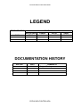
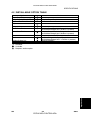
LEGEND
PRODUCT CODE
G065
GESTETNER
P7145
COMPANY
LANIER
RICOH
2145
Aficio AP4510
SAVIN
MLP45
DOCUMENTATION HISTORY
REV. NO.
*
DATE
12/2001
COMMENTS
Original Printing
CÓPIA NÃO CONTROLADA
CÓPIA NÃO CONTROLADA
CÓPIA NÃO CONTROLADA
CÓPIA NÃO CONTROLADA
G065
TABLE OF CONTENTS
INSTALLATION
1. INSTALLATION........................................................................... 1-1
1.1 INSTALLATION REQUIREMENTS .......................................................... 1-1
1.1.1 ENVIRONMENT .............................................................................. 1-1
1.1.2 MACHINE LEVEL ............................................................................ 1-1
1.1.3 MACHINE SPACE REQUIREMENTS ............................................. 1-2
1.1.4 POWER REQUIREMENTS.............................................................. 1-3
1.2 MACHINE INSTALLATION....................................................................... 1-3
1.3 OPTIONAL UNIT INSTALLATION............................................................ 1-3
1.4 SYMBOLS USED IN TEXT....................................................................... 1-3
1.5 LCT INSTALLATION (A683)..................................................................... 1-4
1.5.1 ACCESSORY CHECK ..................................................................... 1-4
1.5.2 INSTALLATION PROCEDURE........................................................ 1-5
1.6 BRIDGE UNIT INSTALLATION (B397)..................................................... 1-7
1.6.1 ACCESSORY CHECK ..................................................................... 1-7
1.6.2 INSTALLATION PROCEDURE........................................................ 1-8
1.7 1000-SHEET FINISHER INSTALLATION (A681)................................... 1-10
1.7.1 ACCESSORY CHECK ................................................................... 1-10
1.7.2 INSTALLATION PROCEDURE...................................................... 1-11
1.8 3000-SHEET FINISHER INSTALLATION (A697)................................... 1-14
1.8.1 ACCESSORY CHECK ................................................................... 1-14
1.8.2 INSTALLATION PROCEDURE...................................................... 1-15
1.9 PUNCH UNIT INSTALLATION (A812).................................................... 1-19
1.9.1 ACCESSORY CHECK ................................................................... 1-19
1.9.2 INSTALLATION PROCEDURE...................................................... 1-20
1.10 MAILBOX INSTALLATION (G909) ....................................................... 1-23
1.10.1 ACCESSORY CHECK ................................................................. 1-23
1.10.2 REQUIREMENT OPTIONS FOR MAIN MACHINE ..................... 1-23
1.10.3 INSTALLATION PROCEDURE.................................................... 1-24
1.11 BRIDGE UNIT FOR MAILBOX INSTALLATION (G912)....................... 1-27
1.11.1 ACCESSORY CHECK ................................................................. 1-27
1.11.2 INSTALLATION PROCEDURE.................................................... 1-28
PREVENTIVE MAINTENANCE
2. PREVENTIVE MAINTENANCE SCHEDULE............................... 2-1
2.1 PM TABLES.............................................................................................. 2-1
2.1.1 PM TABLES FOR THE PRINTER ................................................... 2-1
2.1.2 PM TABLES FOR OPTIONS ........................................................... 2-3
SM
i
CÓPIA NÃO CONTROLADA
G065
CÓPIA NÃO CONTROLADA
REPLACEMENT AND ADJUSTMENT
3. REPLACEMENT AND ADJUSTMENT........................................ 3-1
3.1 GENERAL CAUTIONS ............................................................................. 3-1
3.1.1 LASER UNIT.................................................................................... 3-1
3.1.2 USED TONER ................................................................................. 3-1
3.2 SPECIAL TOOLS AND LUBRICANTS ..................................................... 3-2
3.2.1 SPECIAL TOOLS............................................................................. 3-2
3.2.2 LUBRICANTS .................................................................................. 3-2
3.2.3 SYMBOLS USED IN TEXT .............................................................. 3-2
3.3 FRONT DOOR.......................................................................................... 3-3
3.4 DUPLEX UNIT .......................................................................................... 3-3
3.5 UPPER RIGHT COVER............................................................................ 3-4
3.6 BY-PASS TRAY UNIT .............................................................................. 3-5
3.7 REAR COVERS........................................................................................ 3-6
3.7.1 REAR UPPER COVER.................................................................... 3-6
3.7.2 REAR LOWER COVER ................................................................... 3-6
3.8 LEFT COVERS......................................................................................... 3-7
3.8.1 LEFT UPPER COVER ..................................................................... 3-7
3.8.2 OPERATION PANEL ....................................................................... 3-8
3.8.3 PAPER OUTPUT TRAY .................................................................. 3-9
No Bridge Unit Installed ....................................................................... 3-9
Bridge Unit Installed ............................................................................. 3-9
3.9 LASER UNIT........................................................................................... 3-10
3.9.1 CAUTION DECAL LOCATIONS .................................................... 3-10
3.9.2 LASER UNIT.................................................................................. 3-11
3.9.3 POLYGON MIRROR MOTOR ....................................................... 3-12
3.9.4 LASER SYNCHRONIZATION DETECTOR ................................... 3-13
3.9.5 LD UNIT ......................................................................................... 3-13
Laser Beam Pitch Adjustment ............................................................ 3-14
3.10 PCDU.................................................................................................... 3-15
3.10.1 PHOTOCONDCUTOR CLEANING/DEVELOPMENT UNIT ........ 3-15
3.10.2 DRUM .......................................................................................... 3-16
3.10.3 PICK-OFF PAWLS....................................................................... 3-17
3.10.4 CHARGE ROLLER AND CLEANING ROLLER ........................... 3-18
3.10.5 DRUM CLEANING BLADE .......................................................... 3-19
3.10.6 ID SENSOR ................................................................................. 3-20
3.11 DEVELOPMENT................................................................................... 3-21
3.11.1 DEVELOPMENT UNIT ................................................................ 3-21
3.11.2 DEVELOPMENT FILTER............................................................. 3-22
3.11.3 DEVELOPMENT ROLLER........................................................... 3-23
3.11.4 DEVELOPER ............................................................................... 3-24
3.11.5 TD SENSOR ................................................................................ 3-26
3.12 TRANSFER UNIT ................................................................................. 3-27
3.12.1 TRANSFER BELT UNIT .............................................................. 3-27
3.12.2 TRANSFER BELT........................................................................ 3-28
3.12.3 CLEANING BLADE/TONER OVERFLOW SENSOR................... 3-29
G065
ii
CÓPIA NÃO CONTROLADA
SM
CÓPIA NÃO CONTROLADA
Transfer Belt Cleaning Blade ............................................................. 3-29
Toner Overflow Sensor ...................................................................... 3-29
3.13 PAPER FEED ....................................................................................... 3-30
3.13.1 PICK-UP, SEPARATION, AND FEED ROLLERS........................ 3-30
3.13.2 LOWER RIGHT COVER .............................................................. 3-31
3.13.3 RELAY/UPPER PAPER FEED AND LOWER PAPER FEED
CLUTCHES ................................................................................. 3-32
3.13.4 UPPER PAPER FEED UNIT FOR TRAY 1.................................. 3-33
3.13.5 LOWER PAPER FEED UNIT FOR TRAY 2................................. 3-34
3.13.6 PAPER END/PAPER LIFT/RELAY SENSORS............................ 3-35
3.13.7 REGISTRATION SENSOR .......................................................... 3-36
3.13.8 TRAY LIFT MOTOR..................................................................... 3-38
3.13.9 FEED/DEVELOPMENT MOTOR ................................................. 3-39
3.14 FUSING ................................................................................................ 3-40
3.14.1 FUSING UNIT .............................................................................. 3-40
3.14.2 FUSING UNIT EXIT GUIDE......................................................... 3-41
3.14.3 HOT ROLLER STRIPPERS......................................................... 3-41
3.14.4 FUSING LAMPS .......................................................................... 3-42
Left Side............................................................................................. 3-42
Right Side .......................................................................................... 3-43
3.14.5 THERMISTORS AND THERMOSTATS ...................................... 3-44
3.14.6 HOT ROLLER/PRESSURE ROLLER .......................................... 3-45
3.15 BY-PASS TRAY.................................................................................... 3-47
3.15.1 COVER REPLACEMENT ............................................................ 3-47
3.15.2 BY-PASS FEED/PICK-UP ROLLER ............................................ 3-48
3.15.3 BY-PASS SEPARATION ROLLER REPLACEMENT .................. 3-49
3.15.4 PAPER END SENSOR/PICK-UP SOLENOID ............................. 3-50
3.15.5 PAPER SIZE SENSOR BOARD REPLACEMENT ...................... 3-51
3.15.6 BY-PASS TABLE REMOVAL....................................................... 3-52
3.15.7 PAPER FEED CLUTCH REPLACEMENT ................................... 3-53
3.16 DUPLEX UNIT ...................................................................................... 3-54
3.16.1 DUPLEX COVER REMOVAL ...................................................... 3-54
3.16.2 DUPLEX ENTRANCE SENSOR REPLACEMENT ...................... 3-55
3.16.3 DUPLEX EXIT SENSOR REPLACEMENT.................................. 3-56
3.17 DRIVE AREA ........................................................................................ 3-57
3.17.1 REGISTRATION/TRANSFER BELT CONTACT CLUTCHES ..... 3-57
3.17.2 MAIN MOTOR.............................................................................. 3-58
3.17.3 FUSING/EXIT MOTOR ................................................................ 3-59
3.17.4 FUSING/EXIT CLUTCH ............................................................... 3-60
3.17.5 TONER SUPPLY MOTOR ........................................................... 3-61
3.18 PRINTED CIRCUIT BOARDS .............................................................. 3-62
3.18.1 HIGH VOLTAGE POWER SUPPLY ............................................ 3-62
3.18.2 I/O BOARD .................................................................................. 3-63
3.18.3 BICU BOARD............................................................................... 3-64
3.18.4 PSU ............................................................................................. 3-64
3.19 HARD DISK/CONTROLLER BOARD ................................................... 3-65
To Format the HDD............................................................................ 3-65
3.20 PRINTING ADJUSTMENTS ................................................................. 3-66
3.21 PARALLELOGRAM IMAGE ADJUSTMENT......................................... 3-67
SM
iii
CÓPIA NÃO CONTROLADA
G065
CÓPIA NÃO CONTROLADA
TOUBLESHOOTING
4. TROUBLESHOOTING................................................................. 4-1
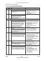
4.1 SERVICE CALL CONDITIONS................................................................. 4-1
4.1.1 SUMMARY....................................................................................... 4-1
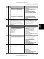
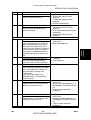
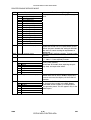
4.1.2 SC CODE DESCRIPTIONS............................................................. 4-2
4.2 ELECTRICAL COMPONENT DEFECTS................................................ 4-13
4.2.1 SENSORS ..................................................................................... 4-13
4.2.2 SWITCHES .................................................................................... 4-14
4.3 BLOWN FUSE CONDITIONS................................................................. 4-15
4.4 LEDS ...................................................................................................... 4-15
BICU .................................................................................................. 4-15
4.5 TEST POINTS ........................................................................................ 4-15
Controller Board ................................................................................. 4-15
SERVICE TABLES
5. SERVICE TABLES ...................................................................... 5-1
5.1 SERVICE PROGRAM MODE................................................................... 5-1
5.1.1 ENTERING AND LEAVING THE SERVICE PROGRAM MODE ..... 5-1
5.2 PRINTER CONTROLLER SERVICE MODE ............................................ 5-2
5.2.1 CONTROLLER SERVICE MODE MENUS ...................................... 5-2
5.2.2 BIT SWITCH PROGRAMMING ....................................................... 5-2
5.2.3 PRINTER CONTROLLER BIT SWITCH SETTINGS ....................... 5-3
5.3 PRINTER ENGINE SERVICE MODE ....................................................... 5-4
Leaving the SP Mode............................................................................. 5-5
5.3.1 SERVICE PROGRAM MODE TABLES ........................................... 5-6
1. Feed (SP1000-00) ............................................................................. 5-6
2. Drum (SP2000-00)........................................................................... 5-10
3. Process (SP3000-00)....................................................................... 5-20
4. HDD (SP4000-00)............................................................................ 5-21
5. Mode (SP5000-00)........................................................................... 5-21
6. Peripherals (SP6000-00) ................................................................. 5-25
7. Data Log (SP7000-00) ..................................................................... 5-26
5.3.2 TEST PATTERN PRINTING .......................................................... 5-29
Test Pattern Table: SP2902-03 Printing Test Patterns ...................... 5-30
5.3.3 INPUT CHECK............................................................................... 5-31
Table 1: By-pass Feed Table Paper Size........................................... 5-34
5.3.4 OUTPUT CHECK........................................................................... 5-35
SP5804 Output Check Table ............................................................. 5-36
5.3.5 MEMORY ALL CLEAR: SP5801.................................................... 5-37
5.3.6 SMC PRINT OUT LISTS: SP5990 ................................................. 5-38
5.4 SOFTWARE DOWNLOAD ..................................................................... 5-39
5.4.1 DOWNLOADING THE SOFTWARE .............................................. 5-39
5.4.2 POWER FAILURE DURING SOFTWARE DOWNLOAD............... 5-40
5.5 SELF-DIAGNOSTIC MODE.................................................................... 5-41
5.5.1 SELF-DIAGNOSTIC MODE AT POWER ON ................................ 5-41
G065
iv
CÓPIA NÃO CONTROLADA
SM
CÓPIA NÃO CONTROLADA
Self-Diagnostic Test Flow .................................................................. 5-41
5.5.2 DETAILED SELF-DIAGNOSTIC MODE ........................................ 5-42
5.6 DIP SWITCHES...................................................................................... 5-43
Controller: DIP SW2........................................................................... 5-43
I/O Board: DIP SW101 ....................................................................... 5-43
DETAILED DESCRIPTIONS
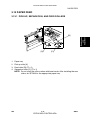
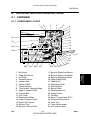
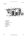
6. DETAILED SECTION DESCRIPTIONS....................................... 6-1
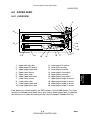
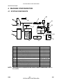
6.1 OVERVIEW .............................................................................................. 6-1
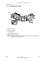
6.1.1 COMPONENT LAYOUT .................................................................. 6-1
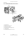
Paper Path ........................................................................................... 6-2
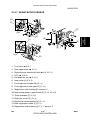
DRIVE LAYOUT................................................................................... 6-3
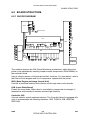
6.2 BOARD STRUCTURE .............................................................................. 6-4
6.2.1 BLOCK DIAGRAM ........................................................................... 6-4
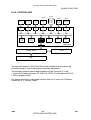
6.2.2 CONTROLLER ................................................................................ 6-6
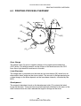
6.3 PRINTING PROCESS OVERVIEW .......................................................... 6-8
Drum Charge........................................................................................ 6-8
Laser Exposure .................................................................................... 6-8
Development ........................................................................................ 6-8
Image Transfer..................................................................................... 6-9
Separation............................................................................................ 6-9
ID Sensor ............................................................................................. 6-9
Cleaning............................................................................................... 6-9
Quenching............................................................................................ 6-9
6.4 LASER EXPOSURE ............................................................................... 6-10
6.4.1 OVERVIEW ................................................................................... 6-10
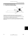
6.4.2 AUTO POWER CONTROL (APC) ................................................. 6-11
6.4.3 DUAL BEAM WRITING.................................................................. 6-12
6.4.4 LASER BEAM PITCH CHANGE MECHANISM ............................. 6-13
6.4.5 LD SAFETY SWITCHES ............................................................... 6-14
6.5 PHOTOCONDUCTOR UNIT (PCU)........................................................ 6-15
6.5.1 OVERVIEW ................................................................................... 6-15
6.5.2 DRIVE MECHANISM ..................................................................... 6-16
6.5.3 DRUM PAWLS............................................................................... 6-16
6.5.4 DRUM TONER SEALS .................................................................. 6-16
6.6 DRUM CHARGE..................................................................................... 6-17
6.6.1 OVERVIEW ................................................................................... 6-17
6.6.2 CHARGE ROLLER VOLTAGE CORRECTION ............................. 6-18
Correction for Environmental Conditions............................................ 6-18
Correction for Paper Width and Thickness (By-pass Tray only)......... 6-19
6.6.3 ID SENSOR PATTERN PRODUCTION TIMING ........................... 6-20
6.6.4 DRUM CHARGE ROLLER CLEANING ......................................... 6-21
6.7 DEVELOPMENT..................................................................................... 6-22
6.7.1 OVERVIEW ................................................................................... 6-22
DRIVE MECHANISM ......................................................................... 6-23
6.7.3 DEVELOPER MIXING ................................................................... 6-23
6.7.4 DEVELOPMENT BIAS................................................................... 6-24
SM
v
CÓPIA NÃO CONTROLADA
G065
CÓPIA NÃO CONTROLADA
Mechanism......................................................................................... 6-24
Correction for Paper Width and Thickness (By-pass Tray only)......... 6-24
6.7.5 TONER SUPPLY ........................................................................... 6-25
Toner Bottle Replenishment Mechanism ........................................... 6-25
Toner Supply Mechanism .................................................................. 6-26
Toner Density Control ........................................................................ 6-26
Sensor Control Mode ......................................................................... 6-27
Image Pixel Count Mode.................................................................... 6-27
6.7.6 TONER NEAR END/END DETECTION......................................... 6-28
Standard Method................................................................................ 6-28
Adjustable Near-end Warning Method ............................................... 6-28
6.7.7 TONER END RECOVERY............................................................. 6-29
6.7.8 TONER SUPPLY WITH ABNORMAL SENSORS.......................... 6-29
6.8 DRUM CLEANING AND TONER RECYCLING...................................... 6-30
6.8.1 DRUM CLEANING......................................................................... 6-30
6.8.2 TONER RECYCLING .................................................................... 6-30
6.9 PAPER FEED ......................................................................................... 6-31
6.9.1 OVERVIEW ................................................................................... 6-31
6.9.2 PAPER FEED DRIVE .................................................................... 6-32
6.9.3 PICK-UP/SEPARATION ROLLER RELEASE................................ 6-32
6.9.4 PAPER LIFT .................................................................................. 6-33
6.9.5 PAPER END DETECTION............................................................. 6-34
6.9.6 PAPER REGISTRATION............................................................... 6-34
6.9.7 PAPER SIZE DETECTION ............................................................ 6-35
6.9.8 PAPER HEIGHT DETECTION....................................................... 6-36
6.10 BY-PASS TRAY.................................................................................... 6-37
6.10.1 OVERVIEW ................................................................................. 6-37
6.10.2 BY-PASS TRAY OPERATION..................................................... 6-38
6.10.3 BY-PASS PAPER SIZE DETECTION.......................................... 6-39
6.11 DUPLEX UNIT ...................................................................................... 6-40
6.11.1 OVERVIEW ................................................................................. 6-40
6.11.2 DUPLEX DRIVE LAYOUT ........................................................... 6-41
6.11.3 DUPLEX BASIC OPERATION..................................................... 6-42
Larger than A4 Lengthwise/LT Lengthwise (SEF).............................. 6-42
Up to A4 Lengthwise/LT Lengthwise (SEF) ....................................... 6-42
6.11.4 DUPLEX UNIT FEED IN AND EXIT MECHANISM...................... 6-43
Feed-in............................................................................................... 6-43
Inversion and Exit............................................................................... 6-43
6.12 IMAGE TRANSFER AND PAPER SEPARATION ................................ 6-44
6.12.1 OVERVIEW ................................................................................. 6-44
6.12.2 BELT DRIVE MECHANISM ......................................................... 6-45
6.12.3 TRANSFER BELT UNIT CONTACT MECHANISM ..................... 6-45
6.12.4 IMAGE TRANSFER AND PAPER SEPARATION
MECHANISM ............................................................................... 6-46
6.12.5 TRANSFER BELT CHARGE ....................................................... 6-47
Mechanism......................................................................................... 6-47
Correction for Paper Width and Thickness......................................... 6-48
Transfer Currents to Leading Edge and Image Areas........................ 6-49
6.12.6 TRANSFER BELT CLEANING MECHANISM.............................. 6-50
G065
vi
CÓPIA NÃO CONTROLADA
SM
CÓPIA NÃO CONTROLADA
6.13 IMAGE FUSING AND PAPER EXIT ..................................................... 6-51
6.13.1 OVERVIEW ................................................................................. 6-51
6.13.2 FUSING DRIVE ........................................................................... 6-52
6.13.3 FUSING ENTRANCE GUIDE SHIFT MECHANISM .................... 6-52
6.13.4 EXIT GUIDE PLATE AND DE-CURLER ROLLERS .................... 6-53
6.13.5 PRESSURE ROLLER.................................................................. 6-53
6.13.6 CLEANING MECHANISM............................................................ 6-53
6.13.7 FUSING TEMPERATURE CONTROL......................................... 6-54
Temperature Control .......................................................................... 6-54
Fusing Idling Temperature ................................................................. 6-55
6.13.8 OVERHEAT PROTECTION......................................................... 6-55
6.14 ENERGY SAVER MODE...................................................................... 6-56
BRIDGE UNIT B397
1. OVERALL MACHINE INFORMATION ........................................ 7-1
1.1
1.2
1.3
1.4
1.5
SPECIFICATIONS .................................................................................... 7-1
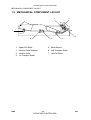
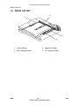
MECHANICAL COMPONENT LAYOUT................................................... 7-2
ELECTRICAL COMPONENT LAYOUT .................................................... 7-3
ELECTRICAL COMPONENT DESCRIPTION .......................................... 7-3
DRIVE LAYOUT ....................................................................................... 7-4
2. DETAILED DESCRIPTION.......................................................... 7-5
2.1 JUNCTION GATE MECHANISM .............................................................. 7-5
3. REPLACEMENT AND ADJUSTMENT........................................ 7-6
3.1 EXIT SENSOR REPLACEMENT.............................................................. 7-6
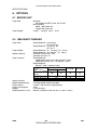
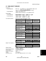
SPECIFICATIONS
8. SPECIFICATIONS....................................................................... 8-1
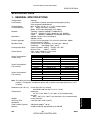
1. GENERAL SPECIFICATIONS.................................................................... 8-1
2. SUPPORTED PAPER SIZES ..................................................................... 8-2
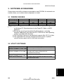
3. SOFTWARE ACCESSORIES..................................................................... 8-3
3.1 PRINTER DRIVERS ........................................................................... 8-3
3.2 UTILITY SOFTWARE ......................................................................... 8-3
. MACHINE CONFIGURATION ...................................................................... 8-4
4.1 SYSTEM COMPONENTS .................................................................. 8-4
4.2 INSTALLABLE OPTION TABLE ......................................................... 8-5
5. OPTIONS.................................................................................................... 8-6
5.1 BRIDGE UNIT..................................................................................... 8-6
5.2 1000-SHEET FINISHER ..................................................................... 8-6
5.3 3000-SHEET FINISHER ..................................................................... 8-7
5.4 LARGE CAPACITY TRAY (LCT) ........................................................ 8-8
5.5 MAILBOX............................................................................................ 8-8
5.6 PAPER TRAY UNIT............................................................................ 8-8
SM
vii
CÓPIA NÃO CONTROLADA
G065
CÓPIA NÃO CONTROLADA
CÓPIA NÃO CONTROLADA
CÓPIA NÃO CONTROLADA
!IMPORTANT SAFETY NOTICES
PREVENTION OF PHYSICAL INJURY
1. Before disassembling or assembling parts of the printer and peripherals,
make sure that the printer power cord is unplugged.
2. The wall outlet should be near the printer and easily accessible.
3. Note that some components of the printer and the paper tray unit are
supplied with electrical voltage even if the main power switch is turned off.
4. If any adjustment or operation check has to be made with exterior covers off
or open while the main switch is turned on, keep hands away from electrified
or mechanically driven components.
5. The inside and the metal parts of the fusing unit become extremely hot while
the printer is operating. Be careful to avoid touching those components with
your bare hands.
HEALTH SAFETY CONDITIONS
Toner and developer are non-toxic, but if you get either of them in your eyes by
accident, it may cause temporary eye discomfort. Try to remove with eye drops
or flush with water as first aid. If unsuccessful, get medical attention.
OBSERVANCE OF ELECTRICAL SAFETY STANDARDS
1. The printer and its peripherals must be installed and maintained by a
customer service representative who has completed the training course on
those models.
2. The NVRAM on the system control board has a lithium battery which can
explode if replaced incorrectly. Replace the NVRAM only with an identical
one. The manufacturer recommends replacing the entire NVRAM. Do not
recharge or burn this battery. Used NVRAM must be handled in accordance
with local regulations.
SAFETY AND ECOLOGICAL NOTES FOR DISPOSAL
1. Do not incinerate toner bottles or used toner. Toner dust may ignite suddenly
when exposed to an open flame.
2. Dispose of used toner, developer, and organic photoconductors in
accordance with local regulations. (These are non-toxic supplies.)
3. Dispose of replaced parts in accordance with local regulations.
4. When keeping used lithium batteries in order to dispose of them later, do not
put more than 100 batteries per sealed box. Storing larger numbers or not
sealing them apart may lead to chemical reactions and heat build-up.
CÓPIA NÃO CONTROLADA
CÓPIA NÃO CONTROLADA
LASER SAFETY
The Center for Devices and Radiological Health (CDRH) prohibits the repair of
laser-based optical units in the field. The optical housing unit can only be repaired
in a factory or at a location with the requisite equipment. The laser subsystem is
replaceable in the field by a qualified Customer Engineer. The laser chassis is not
repairable in the field. Customer engineers are therefore directed to return all
chassis and laser subsystems to the factory or service depot when replacement of
the optical subsystem is required.
!WARNING
Use of controls, or adjustment, or performance of procedures other than
those specified in this manual may result in hazardous radiation exposure.
!WARNING
WARNING: Turn off the main switch before attempting any of the
procedures in the Laser Unit section. Laser beams can seriously damage
your eyes.
Caution Labels
G065RLW.WMF
LASER-3.WMF
LASER-1.WMF
CÓPIA NÃO CONTROLADA
CÓPIA NÃO CONTROLADA
Lithium Batteries (Memory Back-up)
!CAUTION
The danger of explosion exists if a battery of this type is incorrectly
replaced. Replace only with the same or an equivalent type recommended
by the manufacturer. Discard used batteries in accordance with the
manufacturer’s instructions.
Warning Concerning Copyright
Many documents are copyrighted. Such documents may not be reproduced by
copying or in any other form without the express permission of the copyright holder.
Conventions in this Manual
This manual uses several symbols and some simple abbreviations.
Symbol
☛
!
"
#
$
%
HP
T/S
What it means
Refer to section number
See Core Tech Manual for details
Screw
Connector
E-ring
C-ring
Home Position
Transfer/Separation
The following notations are used in text to describe the direction of paper feed:
lengthwise and sideways. The annotations “SEF” and “LEF” denote “Short Edge
Feed” and “Long Edge Feed’. (The arrows indicate the direction of paper feed.)
Lengthwise (SEF)
Sideways (LEF)
CÓPIA NÃO CONTROLADA
CÓPIA NÃO CONTROLADA
CÓPIA NÃO CONTROLADA
REPLACEMENT AND ADJUSTMENT G065
TAB
POSITION 2
SERVICE TABLES G065
TAB
POSITION 5
DETAILED DESCRIPTIONS G065
TAB
POSITION 6
TROUBLESHOOTING G065
TAB
POSITION 3
PREVENTIVE MAINTENANCE G065
TAB
POSITION 4
INSTALLATION G065
TAB
POSITION 1
CÓPIA NÃO CONTROLADA
SPECIFICATIONS G065
CÓPIA NÃO CONTROLADA
TAB
POSITION 8
TAB
POSITION 7
BRIDGE UNIT B397
CÓPIA NÃO CONTROLADA
CÓPIA NÃO CONTROLADA
CÓPIA NÃO CONTROLADA
INSTALLATION
CÓPIA NÃO CONTROLADA
CÓPIA NÃO CONTROLADA
CÓPIA NÃO CONTROLADA
CÓPIA NÃO CONTROLADA
INSTALLATION REQUIREMENTS
Installation
1. INSTALLATION
1.1 INSTALLATION REQUIREMENTS
1.1.1 ENVIRONMENT
1. Temperature Range: 10°C to 32°C (50°F to 89.6°F)
2. Humidity Range:
15 % to 80 % RH
3. Ambient Illumination: Less than 1,500 lux (do not expose to direct sunlight).
4. Ventilation:
3 times/hr/person
5. Avoid areas which are exposed to sudden temperature changes. This includes:
1) Areas directly exposed to cool air from an air conditioner.
2) Areas directly exposed to heat from a heater.
6. Do not place the machine in an area where it will be exposed to corrosive
gases.
7. Do not install the machine at any location over 2,500 m (8,125 ft.) above sea
level.
8. Place the machine on a strong and level base. (Inclination on any side should
be no more than 5 mm.)
9. Do not place the machine where it may be subjected to strong vibrations.
1.1.2 MACHINE LEVEL
Front to back: Within 5 mm (0.2") of level
Right to left:
SM
Within 5 mm (0.2") of level
1-1
CÓPIA NÃO CONTROLADA
G065
CÓPIA NÃO CONTROLADA
INSTALLATION REQUIREMENTS
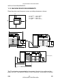
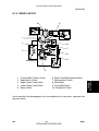
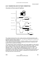
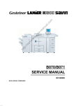
1.1.3 MACHINE SPACE REQUIREMENTS
Place the printer near the power source, providing clearance as shown:
C
A:
B:
C:
D:
In Front:
Left:
To Rear:
Right:
> 75 cm (29.6")
> 10 cm (4")
> 10 cm (4")
> 45 cm (17.8")
D
B
G065I000.WMF
A
630 mm (24.8")
540 mm (21.3")
360 mm (14.2")
625 mm (24.6")
530 mm (20.9")
G065I002.WMF
G065I001.WMF
970 mm (38.2")
625 mm (24.6")
720 mm (28.4")
600 mm (23.6")
1320 mm (52")
G065I003.WMF
The 75 centimeters recommended for the space at the front is for pulling out the
paper tray only. If an operator stands in front of the printer, more space is required.
G065
1-2
CÓPIA NÃO CONTROLADA
SM
CÓPIA NÃO CONTROLADA
1.1.4 POWER REQUIREMENTS
!CAUTION
1. Make sure the plug is firmly inserted in the outlet.
2. Connect the printer to an independent power source. Avoid connecting
the printer to a power supply shared with another machine.
3. Always ground the machine.
1. Input voltage level: 120 V, 60 Hz: More than 12 A
220 V ~ 240 V, 50 Hz/60 Hz: More than 8 A
2. Permissible voltage fluctuation: ±10%
3. Do not set anything on the power cord.
1.2 MACHINE INSTALLATION
Refer to the Operating Instructions for details.
1.3 OPTIONAL UNIT INSTALLATION
The following options are available for this machine. Refer to the Operating
Instructions for how to install these options.
• PTU (Paper Tray Unit)
• 64/128/256 MB DIMMs
• HDD (Hard Disk)
• IEEE 1394
1.4 SYMBOLS USED IN TEXT
Screw: !
SM
Connector: "
1-3
CÓPIA NÃO CONTROLADA
G065
Installation
MACHINE INSTALLATION
CÓPIA NÃO CONTROLADA
LCT INSTALLATION (A683)
1.5 LCT INSTALLATION (A683)
1.5.1 ACCESSORY CHECK
Check the quantity and condition of the accessories in the box against the following
list:
Description
Q’ty
1. Joint Pin ................................................................................. 2
2. Stepped Screw - M3x18......................................................... 4
3. Magnet Cover ........................................................................ 1
4. NECR (-17, -27 machines)..................................................... 1
5. Installation Procedure ............................................................ 1
G065
1-4
CÓPIA NÃO CONTROLADA
SM
CÓPIA NÃO CONTROLADA
LCT INSTALLATION (A683)
Installation
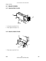
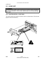
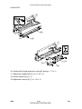
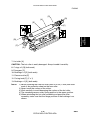
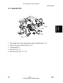
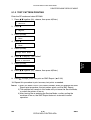
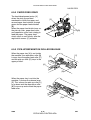
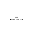
1.1.2 INSTALLATION PROCEDURE
A683I501.WMF
[C]
[B]
A683I500.WMF
[A]
A683I604.WMF
!CAUTION
Switch off the main machine and unplug its power cord before starting the
following procedure.
NOTE: The Paper Tray Unit (G520) must be installed before installing the LCT.
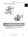
1. Unpack the LCT and remove the tapes.
2. Open the right cover [A] of the paper tray unit.
3. Open the lower right cover [B] and cut the holding band [C].
NOTE: When cutting the holding band, the upper part of the band should be
cut as shown. Otherwise, paper jams may occur.
4. Remove the right lower cover.
SM
1-5
CÓPIA NÃO CONTROLADA
G065
CÓPIA NÃO CONTROLADA
LCT INSTALLATION (A683)
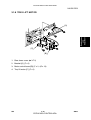
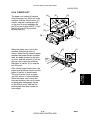
[A]
[E]
[B]
[D]
[C]
A683I503.WMF
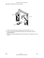
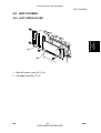
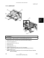
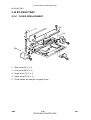
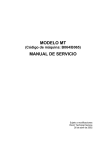
5. Install the joint pins [A].
6. Push the release lever [B] and slide the LCT to the right (front view).
7. Hang the LCT [C] on the joint pins, then secure the brackets [D] (! x 4).
8. Return the LCT to the previous position and connect the LCT cable [E].
9. Open the LCT cover and load the paper.
10. Turn on the ac switch and check the LCT operation.
G065
1-6
CÓPIA NÃO CONTROLADA
SM
CÓPIA NÃO CONTROLADA
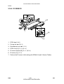
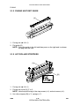
1.6 BRIDGE UNIT INSTALLATION (B397)
1.6.1 ACCESSORY CHECK
Check the quantity and condition of the accessories in the box against the following
list:
Description
Q’ty
1. Stepped Screw ...................................................................... 2
2. Connector Cover.................................................................... 1
3. Exit Mylar ............................................................................... 2
4. Installation Procedure ............................................................ 1
SM
1-7
CÓPIA NÃO CONTROLADA
G065
Installation
BRIDGE UNIT INSTALLATION (B397)
CÓPIA NÃO CONTROLADA
BRIDGE UNIT INSTALLATION (B397)
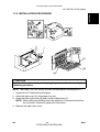
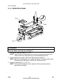
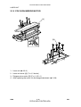
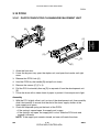
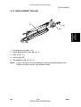
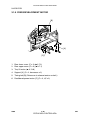
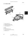
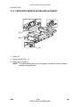
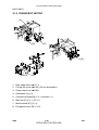
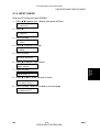
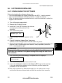
1.1.2 INSTALLATION PROCEDURE
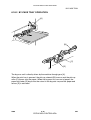
[A]
[B]
[E]
B397I401.WMF
[F]
[C]
[D]
B397I407.WMF
B397I500.WMF
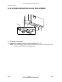
!CAUTION
Switch off the main machine and unplug its power cord before starting the
following procedure.
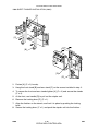
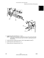
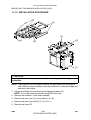
1. Unpack the bridge unit [A] and remove all tapes and shipping retainers.
2. Remove the inner tray [B].
3. On the side of the machine, remove the three small covers [C].
If the optional external output tray (A825) will be installed (instead of a
finisher), do Step 4.
4. Remove the two small covers [D].
5. Remove the cover [E] (! x 1)
6. Remove the cap [F].
7. Remove the paper height sensor (! x 2, " x 1)
G065
1-8
CÓPIA NÃO CONTROLADA
SM
CÓPIA NÃO CONTROLADA
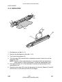
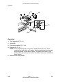
BRIDGE UNIT INSTALLATION (B397)
Installation
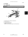
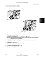
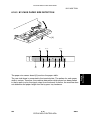
[A]
[E]
[B]
B397I402.WMF
[D]
[C]
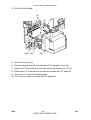
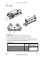
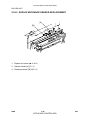
B397I444.WMF
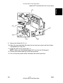
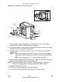
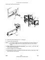
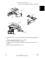
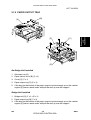
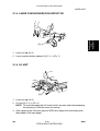
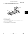
8. If an optional finisher is to be installed, attach two mylars [A] to the bridge unit.
9. Remove the cover [B].
10. Install the bridge unit [C] (! x 2).
11. Connect the bridge unit I/F harnesses [D] (" x 2).
12. Install the connector cover [E].
13. Turn on the main switch and check the bridge unit operation (make sure that
there are no paper jams).
SM
1-9
CÓPIA NÃO CONTROLADA
G065
CÓPIA NÃO CONTROLADA
1000-SHEET FINISHER INSTALLATION (A681)
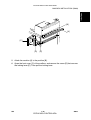
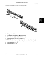
1.7 1000-SHEET FINISHER INSTALLATION (A681)
1.7.1 ACCESSORY CHECK
Check the quantity and condition of the accessories in the box against the following
list:
Description
Q’ty
1. Front Stand ............................................................................ 1
2. Rear Stand............................................................................. 1
3. Knob Screw ........................................................................... 1
4. Screw - M4x12....................................................................... 6
5. NECR (-17 machine) ............................................................. 1
6. Installation Procedure ............................................................ 1
7. Screw - M4x10....................................................................... 1
8. Tray ....................................................................................... 1
9. Snap ring ............................................................................... 1
G065
1-10
CÓPIA NÃO CONTROLADA
SM
CÓPIA NÃO CONTROLADA
1000-SHEET FINISHER INSTALLATION (A681)
Installation
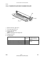
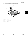
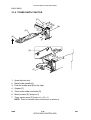
1.1.2 INSTALLATION PROCEDURE
A681I701.WMF
A681I702.WMF
!CAUTION
Switch off the main machine and unplug its power cord before starting the
following procedure.
NOTE: The bridge unit (B397) and paper tray unit (G520) must be installed before
installing this finisher.
If the mailbox (G909) will be installed, first install the mailbox, then the
bridge unit for the mailbox (G912), and finally install the finisher.
1. Unpack the finisher and remove the tapes and retainers.
SM
1-11
CÓPIA NÃO CONTROLADA
G065
CÓPIA NÃO CONTROLADA
1000-SHEET FINISHER INSTALLATION (A681)
[A]
[C]
[B]
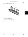
A681I704.WMF
[D]
[E]
A681I705.WMF
2. Fasten [A] (! x 2) loosely.
3. Hang the front stand [B] and rear stand [C] on the screws installed in step 2.
4. To secure the front and rear stands tighten [A] (! x 2) and secure the stands
(! x 4).
5. At the front, use handle [D] to pull out the stapler unit.
6. Remove the locking lever [E] (! x 1).
7. Align the finisher on the stands, and lock it in place by pushing the locking
lever.
8. Secure the locking lever (! x 1) and push the stapler unit into the finisher.
G065
1-12
CÓPIA NÃO CONTROLADA
SM
CÓPIA NÃO CONTROLADA
Installation
1000-SHEET FINISHER INSTALLATION (A681)
[F]
[C]
[A]
[D]
A681I706.WMF
[E]
[B]
9. Secure the finisher [A] (! x 1).
10. Adjust the securing knobs [B] under the front and rear stands until the finisher
is perpendicular to the floor.
11. Install the shift tray [C] (snap ring x 1).
NOTE: Make sure that the three pegs [D] fit into the slots [E] properly.
12. Connect the finisher cable [F] to the main machine.
13. Turn on the main power switch and check the finisher operation.
SM
1-13
CÓPIA NÃO CONTROLADA
G065
CÓPIA NÃO CONTROLADA
3000-SHEET FINISHER INSTALLATION (A697)
1.8 3000-SHEET FINISHER INSTALLATION (A697)
1.8.1 ACCESSORY CHECK
Check the quantity and condition of the accessories in the box against the following
list:
Description
Q’ty
1. Front joint bracket .................................................................. 1
2. Rear joint bracket................................................................... 1
3. Entrance guide plate.............................................................. 1
4. Shift tray................................................................................. 1
5. Shift tray guide....................................................................... 1
6. Staple position decal.............................................................. 1
7. Screw - M3x6......................................................................... 2
8. Screw - M4x14....................................................................... 4
9. Screw - M3x8......................................................................... 4
10. Cushion ................................................................................. 1
11. Upper grounding plate ........................................................... 1
12. Lower grounding plate ........................................................... 2
13. NECR (-17 machine) ............................................................. 1
14. Installation procedure ............................................................ 1
G065
1-14
CÓPIA NÃO CONTROLADA
SM
CÓPIA NÃO CONTROLADA
3000-SHEET FINISHER INSTALLATION (A697)
Installation
1.1.2 INSTALLATION PROCEDURE
A697I506.WMF
A697I507.WMF
!CAUTION
Unplug the main machine power cord before starting the following
procedure.
NOTE: The bridge unit (B397) and paper tray unit (G520) must be installed before
installing this finisher.
If the mailbox (G909) will be installed, first install the mailbox, then the
bridge unit for the mailbox (G912), and finally install the finisher.
1. Unpack the finisher and remove the tapes.
SM
1-15
CÓPIA NÃO CONTROLADA
G065
CÓPIA NÃO CONTROLADA
3000-SHEET FINISHER INSTALLATION (A697)
[B]
[A]
[C]
A697I558.WMF
2. Install the front joint bracket [A] and rear joint bracket [B] (! x 2 ea.).
3. Peel off the backing of the double-sided tape that is attached to the lower
grounding plate [C].
4. Attach one lower grounding plate to the center position of the paper tray unit as
shown.
G065
1-16
CÓPIA NÃO CONTROLADA
SM
CÓPIA NÃO CONTROLADA
Installation
3000-SHEET FINISHER INSTALLATION (A697)
[B]
[A]
[C]
A697I559.WMF
5. Attach the cushion [A] at the position [B].
6. Install the entrance guide plate [C] (! x 2).
SM
1-17
CÓPIA NÃO CONTROLADA
G065
CÓPIA NÃO CONTROLADA
3000-SHEET FINISHER INSTALLATION (A697)
[C]
A697I534.WMF
[G]
[D]
[B]
[A]
[E]
[F]
A697I550.WMF
7. If the customer requires the punch unit, install it now, before attaching the
finisher to the machine. See ‘Punch Unit Installation’.
8. Open the front door of the finisher, and remove the screw [A] that secures the
locking lever [B]. Then pull the locking lever.
9. Align the finisher on the joint brackets, and lock it in place by pushing the
locking lever.
NOTE: 1) Before securing the locking lever, make sure that the top edges of
the finisher and the copier are parallel from front to rear as shown
[C].
2) Secure the locking lever (! x 1) and close the front door.
10. Install the shift tray guide [D] on the shift tray. If the customer does not wish to
install it on the shift tray, store it at the location [E].
NOTE: The shift tray guide helps to properly stack exiting paper. However, it
reduces the capacity of the shift tray by 50, from 3,000 to 2,950.
11. Install the shift tray [F] (! x 4).
12. Connect the finisher cable [G] to the main machine.
13. Turn on the main power switch and check the finisher operation.
G065
1-18
CÓPIA NÃO CONTROLADA
SM
CÓPIA NÃO CONTROLADA
1.9 PUNCH UNIT INSTALLATION (A812)
1.9.1 ACCESSORY CHECK
Check the quantity and condition of the accessories in the box against the following
list:
Description
Q’ty
1. Spacer - 2 mm ....................................................................... 1
2. Spacer - 1 mm ....................................................................... 2
3. Stepped screw - Short ........................................................... 1
4. Stepped screw - Long............................................................ 1
5. Punch unit knob ..................................................................... 1
6. Spring .................................................................................... 1
7. Harness - Long ...................................................................... 1
8. Harness - Short...................................................................... 1
9. Hopper................................................................................... 1
10. Punch position decal.............................................................. 1
11. Tapping screw - M4x10.......................................................... 2
12. Screw with flat washer - M4x6 ............................................... 1
13. NECR..................................................................................... 1
SM
1-19
CÓPIA NÃO CONTROLADA
G065
Installation
PUNCH UNIT INSTALLATION (A812)
CÓPIA NÃO CONTROLADA
PUNCH UNIT INSTALLATION (A812)
1.1.2 INSTALLATION PROCEDURE
[A]
[D]
[B]
A812I761.WMF
[C]
A812I763.WMF
!CAUTION
Unplug the copier power cord and remove the 3,000-sheet finisher from the
copier before starting the following procedure.
1. Unpack the punch unit and remove the shipping retainers [A] (! x 4) and [B] (!
x 1).
2. Open the front door and remove the hopper cover [C] (! x 2).
3. Remove the finisher rear cover (! x 2) and remove the transport guide plate
[D] (! x 4).
G065
1-20
CÓPIA NÃO CONTROLADA
SM
CÓPIA NÃO CONTROLADA
Installation
PUNCH UNIT INSTALLATION (A812)
[A]
[B]
A812I510.WMF
[D]
[C]
A812I765.WMF
4. Install the spacer [A] (thickness = 2 mm).
NOTE: There are three spacers in the accessory box. Do not lose the other
two spacers (1-mm) because they are used for adjusting the punch
hole position.
5. Install the punch unit [B] and secure it with a long stepped screw [C].
6. Install the punch unit knob [D] (! x 1).
7. Secure the rear of the punch unit (! x 2).
SM
1-21
CÓPIA NÃO CONTROLADA
G065
CÓPIA NÃO CONTROLADA
PUNCH UNIT INSTALLATION (A812)
[E]
[B]
[C]
[A]
A812I767.WMF
[D]
A812I511.WMF
[F]
A812I512.WMF
8. Install the sensor bracket [A] (! x 1, spring x1).
9. Connect the harnesses [B].
NOTE: 1) The harness binders [C] must not be between the harness clamps [D].
2) The harness binder [E] must be positioned to the left of the harness
clamp.
10. When a three-punch-hole unit is installed: Turn on switch 1 of DIP SW 100
on the finisher control board.
11. Slide the hopper [F] into the finisher.
12. Reassemble the finisher and attach the 3000-sheet finisher to the copier, then
check the punch unit function.
G065
1-22
CÓPIA NÃO CONTROLADA
SM
CÓPIA NÃO CONTROLADA
1.10 MAILBOX INSTALLATION (G909)
1.10.1 ACCESSORY CHECK
Check the quantity and condition of the accessories in the box against the following
list:
Description
Q’ty
1. Front joint bracket .................................................................. 1
2. Rear joint bracket................................................................... 1
3. Exit guide mylar ..................................................................... 1
4. Proof tray attachment ............................................................ 1
5. Upper grounding plate ........................................................... 1
6. Lower grounding plate ........................................................... 2
7. Cushion ................................................................................. 1
8. Tapping screw - M4x14.......................................................... 4
9. Bin decals .............................................................................. 1
10. Installation procedure ............................................................ 1
1.1.2 REQUIREMENT OPTIONS FOR MAIN MACHINE
When the mailbox is going to be installed on this printer, the following options must
be installed first.
• Bridge unit type 450 (B397)
• Paper tray unit - PS430 (G520)
SM
1-23
CÓPIA NÃO CONTROLADA
G065
Installation
MAILBOX INSTALLATION (G909)
CÓPIA NÃO CONTROLADA
MAILBOX INSTALLATION (G909)
1.1.3 INSTALLATION PROCEDURE
G909I500.WMF
[B]
[A]
[C]
G909I559.WMF
!CAUTION
Unplug the main machine power cord before starting the following
procedure.
NOTE: If a finisher will be installed, first install this mailbox, then the bridge unit for
the mailbox (G912), and finally install the finisher.
1. Unpack the finisher and remove the pieces of tape.
2. Attach the front joint bracket [A] and rear joint bracket [B] to the main machine
(! x 2 ea.).
3. Peel off the backing of the double-sided tape that is attached to the lower
grounding plate [C].
4. Attach one lower grounding plate to the center of the bottom edge of the paper
tray unit as shown.
G065
1-24
CÓPIA NÃO CONTROLADA
SM
CÓPIA NÃO CONTROLADA
Installation
MAILBOX INSTALLATION (G909)
[B]
[A]
[C]
[D]
[E]
G909I550.WMF
5. Attach the cushion [A] to the position [B].
6. Open the front cover [C] of the mailbox, and remove the screw [D] that secures
the locking lever [E]. Then pull the locking lever.
SM
1-25
CÓPIA NÃO CONTROLADA
G065
CÓPIA NÃO CONTROLADA
MAILBOX INSTALLATION (G909)
[B]
[A]
[C]
G909I503.WMF
G909I552.WMF
7. Align the mailbox on the joint brackets, and lock it in place by pushing the
locking lever [A].
8. Secure the locking lever (! x 1) and close the front door.
9. Connect the mailbox cable [B] to the main machine.
10. Peel off the backing of the double-sided tape that is attached to the proof tray
attachment [C].
11. Install the proof tray attachment on the proof tray.
12. Turn on the main switch and check the mailbox operation.
G065
1-26
CÓPIA NÃO CONTROLADA
SM
CÓPIA NÃO CONTROLADA
1.11 BRIDGE UNIT FOR MAILBOX INSTALLATION (G912)
1.11.1 ACCESSORY CHECK
Check the quantity and condition of the accessories in the box against the following
list:
Description
Q’ty
1. Guide plate bracket ............................................................... 1
2. Cable..................................................................................... 1
3. Cover switch.......................................................................... 1
4. Grounding bracket................................................................. 1
5. Finisher shielding plate.......................................................... 1
6. Screw - M4x8 ........................................................................ 9
7. Screw - M4x4 ........................................................................ 4
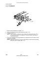
8. Screw - M3x6 ........................................................................ 2
SM
1-27
CÓPIA NÃO CONTROLADA
G065
Installation
BRIDGE UNIT FOR MAILBOX INSTALLATION (G912)
CÓPIA NÃO CONTROLADA
BRIDGE UNIT FOR MAILBOX INSTALLATION (G912)
1.11.2 INSTALLATION PROCEDURE
[A]
[D]
[A]
[E]
[B]
G912I506.WMF
[C]
G909I508.WMF
!CAUTION
Unplug the main machine power cord before starting the following
procedure.
NOTE: The bridge unit for the mailbox must be installed when both the mailbox
and a finisher will be installed. Install the mailbox first, then this bridge unit,
and finally the finisher
1. Unpack the bridge unit and remove the shipping retainers [A].
NOTE: Do not remove the protective sheet [B] at this time.
2. Remove the mailbox if it has been installed.
3. Remove the rear cover [C] of the mailbox (! x 8).
4. Remove the proof tray unit [D] (! x 6, " x 1).
5. Remove the cover [E].
G065
1-28
CÓPIA NÃO CONTROLADA
SM
CÓPIA NÃO CONTROLADA
Installation
BRIDGE UNIT FOR MAILBOX INSTALLATION (G912)
[B]
[C]
[A]
G912I503.WMF
[F]
[D]
G912I504.WMF
[E]
G912I505.WMF
[D]
6. Open the left front cover [A] of the mailbox, and remove the inner plate [B] (! x
3).
7. Install the guide plate bracket [C] (! x 4 - M4x4).
8. Route the cable [D] and clamp it as shown.
9. Connect the cover switch [E] to the cable then install the cover switch (! x 2 M4x8).
10. Remove the paper guide plate [F] (! x 2).
SM
1-29
CÓPIA NÃO CONTROLADA
G065
CÓPIA NÃO CONTROLADA
BRIDGE UNIT FOR MAILBOX INSTALLATION (G912)
[B]
[C]
[A]
G912I501.WMF
[D]
[F]
[E]
G912I507.WMF
[H]
[G]
[H]
G912I508.WMF
11. Pull up the tab [A] of the protective sheet.
NOTE: 1) Do not remove the protective sheet at this time.
2) Make sure that all mylars are held between the two folded halves of
the protective sheet.
12. Turn over the bridge unit [B] and insert the protective sheet [C] into the gap [D]
between the paper guides, then put the bridge unit on the mailbox [E].
NOTE: When holding the bridge unit, do not touch the timing belt. Otherwise
the timing belt may come off the gear.
13. Remove the tape [F] for the protective sheet.
14. Open the upper paper guide [G] then pull out the protective sheet [H].
NOTE: Check that all mylars are set into the gap between the paper guides.
G065
1-30
CÓPIA NÃO CONTROLADA
SM
CÓPIA NÃO CONTROLADA
Installation
BRIDGE UNIT FOR MAILBOX INSTALLATION (G912)
[B]
[C]
[E]
[B]
[A]
[D]
[C]
[B]
G912I509.WMF
[B]
G912I513.WMF
[G]
[F]
G912I510.WMF
15. Secure the bridge unit [A] (! x 4 - M4x8).
16. Route the cables [B] through the openings [C].
17. Route the solenoid harness [D] through the opening [E].
18. Connect the cables to the solenoid and sensors and clamp the cable as shown.
19. Reinstall the rear cover and proof tray unit.
20. Install the mailbox on the main machine (refer to the Mailbox Installation
procedure for more detail).
If installing the 3000-sheet finisher (A697), do steps 21 to 25.
21. Install the front joint bracket [F] and rear joint bracket [G] which are contained in
the finisher’s accessory box.
SM
1-31
CÓPIA NÃO CONTROLADA
G065
CÓPIA NÃO CONTROLADA
BRIDGE UNIT FOR MAILBOX INSTALLATION (G912)
[B]
G912I502.WMF
[A]
[C]
G912I512.WMF
22. Remove the seal [A].
23. Attach the grounding bracket [B] (! x 3 - M4x8).
24. Attach the shielding plate [C] to the finisher (! x 2 - M3x8).
25. Attach the finisher to the mailbox (refer to the finisher installation procedure).
26. Turn on the main switch of the main machine and check the bridge unit
operation. (Select a print mode that uses the finisher.)
G065
1-32
CÓPIA NÃO CONTROLADA
SM
CÓPIA NÃO CONTROLADA
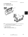
PREVENTIVE MAINTANENCE
CÓPIA NÃO CONTROLADA
CÓPIA NÃO CONTROLADA
CÓPIA NÃO CONTROLADA
CÓPIA NÃO CONTROLADA
PM TABLES
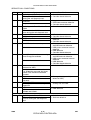
2. PREVENTIVE MAINTENANCE SCHEDULE
2.1 PM TABLES
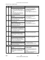
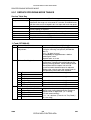
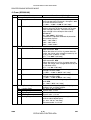
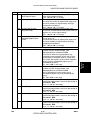
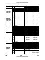
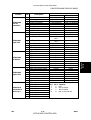
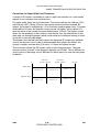
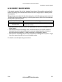
2.1.1 PM TABLES FOR THE PRINTER
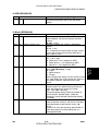
NAME
Maintenance Kit Type 4510A
Maintenance Kit Type 4510B
Preventive
Maintenance
Two maintenance kits are provided for customers.
CONTENTS
PCDU (Photo Conductor Cleaning/Development Unit)
Fusing Unit and Transfer Unit
Components marked with an asterisk (*) should be inspected, serviced, and
replaced without the maintenance kits.
NOTE: Amounts mentioned as the PM interval indicate the number of prints.
Symbol key: C: Clean, R: Replace, L: Lubricate, I: Inspect
EM
150K
300K
450K
R
R
R
R
R
C
R
R
C
R
C
C
C
C
R
R
R
C
C
C
Side Seal
I
I
I
DEVELOPMENT
Development Drive Gears
Development Filter*
Developer*
Entrance Seal
Side Seal
Development Roller
I
R
I
I
I
C
I
R
R
I
I
C
I
R
I
I
I
C
PCDU
DRUM (OPC) AREA
Charge Roller*
Cleaning Roller*
Quenching Lamp
Pick-off Pawls*
Spurs
ID Sensor
CLEANING UNIT
Drum Cleaning Blade*
Cleaning Entrance Seal
SM
NOTE
Dry cloth
R
C
Dry cloth or alcohol
Perform SP3001-02 after
blower brush cleaning.
Blower brush, replace if
required.
Replace every 5 PM (750 K)
Dry cloth
2-1
CÓPIA NÃO CONTROLADA
G065
CÓPIA NÃO CONTROLADA
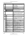
PM TABLES
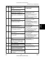
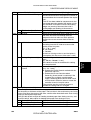
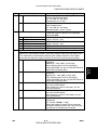
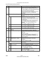
PAPER FEED
Registration Roller
Paper Feed Roller*
Separation Roller*
Pick-up Roller*
Paper Feed Roller
(By-pass feed table)*
Separation Roller
(By-pass feed table)*
Pick-up Roller
(By-pass feed table)
Paper Feed Guides
Relay Rollers
Bottom Plate Pad
Bottom Plate Pad
(By-pass feed)
Registration Sensor
Paper Feed Roller Gear
(By-pass feed)
EM
150K
300K
450K
NOTE
C
I
I
I
C
R
R
R
C
R
R
R
C
R
R
R
I
R
R
R
Water or alcohol.
Check counter value for each
(SP7204). If ≥ 150 K, replace
roller. After replacing the roller,
do SP7816 to reset counter.
I
R
R
R
I
R
R
R
C
C
C
C
C
C
C
C
C
C
C
C
C
C
C
L
L
L
C
C
C
C
C
C
Water or alcohol.
Water or alcohol.
R
R
R
Dry cloth
R
R
R
C
C
C
C
C
C
C
C
C
C
C
C
C
C
C
R
R
R
C
L
C
C
C
R
R
R
C
L
R
C
C
R
R
R
C
L
C
C
C
DUPLEX UNIT
Upper Transport Roller
Lower Transport Roller
TRANSFER BELT UNIT
Transfer Belt*
Transfer Belt Cleaning
Blade*
Transfer Belt Rollers
Entrance Seal
Transfer Entrance Guide
Used Toner Tank
FUSING UNIT/PAPER EXIT
Fusing Entrance and Exit
Guide Plates
Hot Roller*
Pressure Roller*
Fusing Thermistors*
Cleaning Roller
Cleaning Roller Bushings
Hot Roller Strippers*
Paper Exit Guide Ribs
Exit Sensor
C
C
I
DRIVE
Drive Belts
G065
I
Water or alcohol.
Water or alcohol.
Water or alcohol.
Water or alcohol.
Blower brush
Silicone Grease G-501.*
Dry cloth
Dry cloth
Dry cloth
Empty the tank.
Water or alcohol.
Water or alcohol.
Grease: Barrierta JFE 55/2
Water or alcohol.
Water or alcohol.
Blower brush
Replace if necessary
2-2
CÓPIA NÃO CONTROLADA
SM
CÓPIA NÃO CONTROLADA
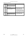
PM TABLES
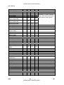
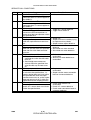
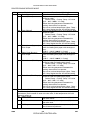
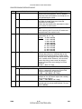
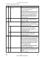
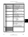
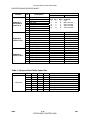
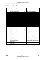
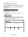
2.1.2 PM TABLES FOR OPTIONS
NOTE: Amounts mentioned as the PM interval indicate the number of prints.
EM
PAPER TRAY UNIT G520
Paper Feed Rollers
Pick-up Rollers
Separation Rollers
Relay Rollers
Bottom Plate Pad
EM
150K
300K
450K
NOTE
R
R
R
R
R
R
R
C
C
R
C
C
R
C
C
Check counter with SP7204. If
≥ 150 K, replace roller. After
replacing the roller, do SP7816
to reset counter.
Dry or damp cloth
Dry or damp cloth
150K
300K
450K
NOTE
Check counter with SP7204. If
≥ 150 K, replace roller. After
replacing the roller, do SP7816
to reset counter.
LCT A683
Paper Feed Roller
Pick-up Roller*
Separation Roller*
Bottom Plate Pad
R
R
R
R
R
C
R
R
C
R
R
C
300K
450K
I
C
I
C
I
I
I
I
EM
150K
1000-SHEET/3000-SHEET FINISHER
Rollers
C
Brush Roller (A681)
I
I
Discharge Brush
C
C
Sensors
C
Jogger Fences
I
I
Punch Waste Hopper
I
I
Dry or damp cloth
NOTE
Water or alcohol.
Replace if required.
Dry cloth
Blower brush
Replace if required.
Empty hopper.
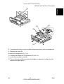
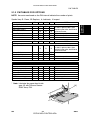
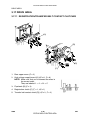
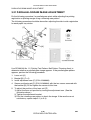
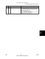
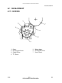
* Note: Lubricate the paper feed clutch
gear [A] with Silicone Grease
G501 every P.M.
[A]
G065P500.WMF
SM
2-3
CÓPIA NÃO CONTROLADA
G065
Preventive
Maintenance
Symbol key: C: Clean, R: Replace, L: Lubricate, I: Inspect
CÓPIA NÃO CONTROLADA
CÓPIA NÃO CONTROLADA
CÓPIA NÃO CONTROLADA
REPLACEMENT AND ADJUSTMENT
CÓPIA NÃO CONTROLADA
CÓPIA NÃO CONTROLADA
CÓPIA NÃO CONTROLADA
CÓPIA NÃO CONTROLADA
GENERAL CAUTIONS
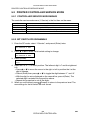
3. REPLACEMENT AND ADJUSTMENT
3.1 GENERAL CAUTIONS
!CAUTION
To avoid damage to the transfer belt, drum, or development unit when it is
removed or re-installed, never turn off either power switch while electrical
components are active.
Turn off the main power switch and unplug the machine before attempting
any of the procedures in this section.
3.1.1 LASER UNIT
1. Do not loosen the screws that secure the LD drive board to the laser diode
casing. Doing so would throw the LD unit out of adjustment.
2. Do not adjust the variable resistors on the LD unit, as they are adjusted in the
factory.
3. The polygon mirror and F-theta lenses are very sensitive to dust. Do not open
the optical housing unit.
4. Do not touch the glass surface of the polygon mirror motor unit with bare
hands.
5. After replacing the LD unit, do the laser beam pitch adjustment. Otherwise, an
SC condition will be generated.
3.1.2 USED TONER
1. Dispose of used toner in accordance with local regulations. Never throw toner
into an open flame, for toner dust may ignite.
SM
3-1
CÓPIA NÃO CONTROLADA
G065
Replacement
and
Adjustment
!CAUTION
CÓPIA NÃO CONTROLADA
SPECIAL TOOLS AND LUBRICANTS
3.2 SPECIAL TOOLS AND LUBRICANTS
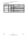
3.2.1 SPECIAL TOOLS
Part Number
A2309003
A2309004
A2309352
A2309351
G0219350
Description
Adjustment Cam – Laser Unit
Positioning Pin – Laser Unit
Flash Memory Card – 4MB
Case – Flash Memory Card
Parallel Loopback Connector
Q’ty
1
1
1
1
1
3.2.2 LUBRICANTS
Part Number
A2579300
52039501
Description
Grease Barrierta S552R
Silicone Grease G-501
Q’ty
1
1
3.2.3 SYMBOLS USED IN TEXT
Screw: !
G065
Connector: " C-clamp (snap ring): # E-clamp: $
3-2
CÓPIA NÃO CONTROLADA
SM
CÓPIA NÃO CONTROLADA
FRONT DOOR
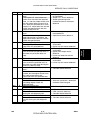
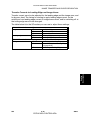
3.3 FRONT DOOR
Replacement
and
Adjustment
[A]
[B]
G065R951.WMF
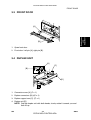
1. Open front door.
2. Front door. Left pin [A], right pin [B].
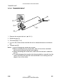
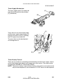
3.4 DUPLEX UNIT
[A]
[C]
[B]
[D]
G065R003.WMF
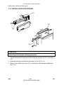
1. Connector cover [A] (! x 1)
2. Duplex connectors [B] (" x 2)
3. Duplex support arm [C] (# x 1)
4. Duplex unit [D]
NOTE: Grip the duplex unit with both hands, slowly rotate it towards you and
then lift up.
SM
3-3
CÓPIA NÃO CONTROLADA
G065
CÓPIA NÃO CONTROLADA
UPPER RIGHT COVER
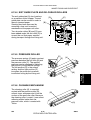
3.5 UPPER RIGHT COVER
[C]
[B]
[A]
G065R945.WMF
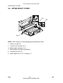
NOTE: Work carefully to avoid damaging the development roller.
1. Duplex unit (☛ 3.4)
2. Transfer belt unit (☛ 3.12.1)
3. Metal support arm [A] (! x 1)
4. Band support arm [B] (loop fastener)
5. Connector [C] (" x 1)
6. Upper right cover (# x 1, bushing x 1)
G065
3-4
CÓPIA NÃO CONTROLADA
SM
CÓPIA NÃO CONTROLADA
BY-PASS TRAY UNIT
3.6 BY-PASS TRAY UNIT
[B]
Replacement
and
Adjustment
[C]
[D]
[A]
G065R952.WMF
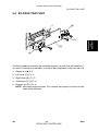
Use this procedure to remove the complete by-pass tray unit from the machine. If
you wish to remove only the table, or some of the components of this unit, ☛ 3.15.
1. Duplex unit (☛ 3.4)
2. Left cover [A] (! x 1)
3. Right cover [B] (! x 1)
4. Connectors [C] (" x 2)
5. By-pass unit [D] (! x 4)
NOTE: After removing the screws, lift to unhook the by-pass tray unit from the
frame of the machine.
SM
3-5
CÓPIA NÃO CONTROLADA
G065
CÓPIA NÃO CONTROLADA
REAR COVERS
3.7 REAR COVERS
3.7.1 REAR UPPER COVER
[B]
[A]
G065R953.WMF
1. Left corner cover [A] (! x 2)
2. Rear upper cover [B] (! x 2)
3.7.2 REAR LOWER COVER
[A]
G065R954.WMF
1. Rear lower cover [A] (! x 4)
G065
3-6
CÓPIA NÃO CONTROLADA
SM
CÓPIA NÃO CONTROLADA
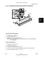
LEFT COVERS
3.8 LEFT COVERS
Replacement
and
Adjustment
3.8.1 LEFT UPPER COVER
[A]
[B]
G065R955.WMF
1. Rear left corner cover [A] (! x 2)
2. Left upper cover [B] (! x 4)
SM
3-7
CÓPIA NÃO CONTROLADA
G065
CÓPIA NÃO CONTROLADA
LEFT COVERS
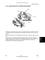
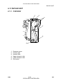
3.1.2 OPERATION PANEL
[A]
[D]
[B]
[C]
G065R919.WMF
!WARNING
The fusing unit below the cover is hot. Allow the machine to cool for a few
minutes before you begin the procedure.
1. Fusing unit cover [A] (caps x 2, ! x 2)
NOTE: Insert the tip of a screwdriver into the slot to release the plastic hook
and lift. Exert very little pressure to avoid breaking the hooks.
2. After removing the screws, slide cover [B] forward to remove it.
NOTE: Before re-installing the cover, open the duplex unit and carefully insert
the brackets on the bottom of the cover into the slots [C].
3. Operation panel [D] (! x 2, " x 2)
NOTE: Turn over the fusing unit cover and pull off the operation panel to
expose the connector.
G065
3-8
CÓPIA NÃO CONTROLADA
SM
CÓPIA NÃO CONTROLADA
LEFT COVERS
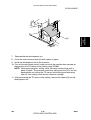
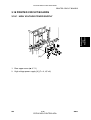
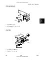
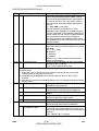
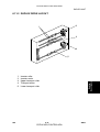
3.1.3 PAPER OUTPUT TRAY
[B]
[D]
Replacement
and
Adjustment
[A]
[C]
G065R920.WMF
[E]
G065R921.WMF
No Bridge Unit Installed
1. Sub copy tray [A]
2. Paper sensor ass’y [B] (! x 2)
3. Cover [C] (! x 1)
4. Paper output tray [D] (! x 3)
5. If the duct on the bottom of the paper output tray base hangs up on the vertical
support [E] below, reach under and pull the duct up over the support.
Bridge Unit Installed
1. Bridge unit [A] (! x 2, " x 2)
2. Paper output tray [B] (! x 3)
3. If the duct on the bottom of the paper output tray base hangs up on the vertical
support [E] below, reach under and pull the duct up over the support.
SM
3-9
CÓPIA NÃO CONTROLADA
G065
CÓPIA NÃO CONTROLADA
LASER UNIT
3.9 LASER UNIT
!WARNING
Turn off the main power switch and unplug the machine before attempting
any of the procedures in this section. Laser beams can seriously damage
your eyes.
3.9.1 CAUTION DECAL LOCATIONS
Two caution decals are located in the laser section as shown below. (See the next
page for removal instructions.)
G060R951.WMF
LASER-3.WMF
LASER-1.WMF
G065RLW.WMF
G065
3-10
CÓPIA NÃO CONTROLADA
SM
CÓPIA NÃO CONTROLADA
LASER UNIT
3.1.2 LASER UNIT
[A]
[C]
[D]
Replacement
and
Adjustment
[B]
[F]
[B]
G065R211.WMF
[G]
[E]
G065R962.WMF
!WARNING
Turn off the main power switch and unplug the machine before attempting
this procedure. Laser beams can seriously damage your eyes.
1. Open the front door and raise the toner bottle holder handle [A].
2. Front door (pins [B] x 2)
3. Inner cover [C] (! x 2, " x 2)
4. Shield glass [D]
5. Shield plate [E] (! x 2)
6. Laser unit connectors [F] (" x 5, " x 1 flat cable)
NOTE: Hold the LD board securely when disconnecting connectors.
7. Laser unit [G] (! x 2)
NOTE: When sliding out the laser unit, do not hold the LD board. Hold the
laser unit casing.
SM
3-11
CÓPIA NÃO CONTROLADA
G065
CÓPIA NÃO CONTROLADA
LASER UNIT
3.1.3 POLYGON MIRROR MOTOR
[A]
[B]
G065R994.WMF
G065R201.WMF
1. Laser unit (☛ 3.9.2)
2. Laser unit cover [A] (! x 4, 2 hooks)
3. Polygon mirror motor [B] (! x 4, " x 1)
4. After replacing the motor, do the image adjustment. (☛ 3.20)
G065
3-12
CÓPIA NÃO CONTROLADA
SM
CÓPIA NÃO CONTROLADA
LASER UNIT
Replacement
and
Adjustment
3.1.4 LASER SYNCHRONIZATION DETECTOR
[A]
G065R206.WMF
1. Laser unit (☛ 3.9.2)
2. Laser synchronization detector [A] (! x 1, " x 1).
3.1.5 LD UNIT
[A]
G065R513.WMF
1. Laser unit (☛ 3.9.2)
2. LD unit [A] (! x 3, " x 1)
NOTE: To avoid damaging the LD board, hold it securely when disconnecting
the connectors. Hold the laser unit casing.
3. After replacing the LD board, perform SP2109 to adjust the laser beam pitch
(described on the next page).
SM
3-13
CÓPIA NÃO CONTROLADA
G065
CÓPIA NÃO CONTROLADA
LASER UNIT
Laser Beam Pitch Adjustment
After replacing the LD board, do the laser beam pitch adjustment. There are two
procedures: one for 400 dpi, and one for 600 dpi. These use the following SPs.
SP2110
SP2109-01
SP2109-02
SP2109-03
SP2109-04
Test Mode Dpi (0: 400 dpi, 8: 600 dpi)
LD Beam Pitch Adjustment – 400 dpi
LD Beam Pitch Adjustment – 600 dpi
LD Beam Pitch Adjustment – 400 dpi Initial Setting
LD Beam Pitch Adjustment – 600 dpi Initial Setting
NOTE: If you do not have an SMC Report for reference, print the SMC Report so
you can look up and match the SP numbers below with the correct name.
1. Set SP2110 to 0 (for 400 dpi), or to 8 (for 600 dpi).
2. Execute SP2109-08 to reset all the beam pitch data.
3. For SP2109-01 input 144.
NOTE: The entry “144” is only a starting reference value that will allow the
machine to operate. It is only a starting point for adjustment.
4. Execute SP2109-03.
5. Print the test pattern onto A3 (11" x 17") paper using SP2902-03 no.15. (☛ 5
Service Tables, 5.1.2 Test Pattern Printing (SP2902).
6. On the test pattern write 144, the value of SP2109-01.
7. Change the value of SP2109-01 and then print another test pattern, repeating
steps 2 to 6. Print about 5 patterns with different values for SP2109-01 (e.g. 48,
96, 192, 240).
8. Check these test patterns. If the laser beam pitch is not correct, the image
looks like a black vertical stripe pattern (see the diagrams below).
NOTE: For example, if the pattern made with the value 192 has fewer obvious
stripes than the other printouts, the correct value is near 192.
9. Fine adjustment: Do steps 2 to 6 to adjust the laser beam pitch position until
thin lines are of uniform thickness (no stripes should appear on the printout).
NOTE: In step 3, input a value estimated to be correct (e.g., if 192 was the
closest, try 182), then do steps 4 and 5, then if necessary go back to
step 2 and try another value.
10. After adjusting the laser beam pitch for 400 dpi, adjust it for 600 dpi, using the
same procedure as for 400 dpi (use the SP modes for 600 dpi). Laser beam
pitch for 600 dpi should be 24 ~ 48 more than for 400 dpi.
Adjustment complete
Adjustment not complete
G065
G065R552.WMF
3-14
G065R553.WMF
CÓPIA NÃO CONTROLADA
SM
CÓPIA NÃO CONTROLADA
PCDU
3.10 PCDU
3.10.1 PHOTOCONDCUTOR CLEANING/DEVELOPMENT UNIT
[B]
[A]
Replacement
and
Adjustment
[C]
G065R905.WMF
[C]
[D]
[E]
G065R906.WMF
1. Open the front door.
2. Lower the by-pass tray, open the duplex unit, and open the transfer unit right
cover.
3. Release the PCDU lock [A].
4. Hold the PCDU by the handle [B] and pull out slowly.
5. Remove the screws [C] (! x 3).
6. Pull the PCU horizontally then up [D] to separate it from the development unit
[E].
7. Cover the drum with a clean sheet of paper to protect it from exposure to light.
Assembly
1. With the PCU slightly offset, set it on top of the development unit, then carefully
slide it horizontally to ensure that the end of the toner supply shutter at the
toner supply port opens.
2. Check the exposed spring on the back of the PCDU.
• If the spring is spread open, the supply port is open.
• If the spring is not open, the supply port is shut. Slide the PCU back and
engage it correctly.
NOTE: If the supply port remains closed, no toner will reach the drum.
SM
3-15
CÓPIA NÃO CONTROLADA
G065
CÓPIA NÃO CONTROLADA
PCDU
3.10.2 DRUM
[C]
[B]
[A]
G065R907.WMF
G065R908.WMF
[D]
[E]
G065R304.WMF
1. PCDU (☛ 3.10.1)
CAUTION: Never touch the drum surface with bare hands.
2. Remove the toner cap [A] and use it to cover the toner port [B].
3. Turn the PCU upside down and remove the lower cover [C] (! x 2, pawls x 3)
4. Press at ➀ to release the charge roller [D], release the charge roller ➁, press
the drum [E] to the front, and then remove the drum ➂.
5. SP adjustments.
Charge Roller Bias Adjustment
2001-01
ID Sensor Initial Setting
Image Transfer Current – Image Face
Image Transfer Current – Image Back
Image Transfer Current – Lead Edge Face
Image Transfer Current – Image Face By-pass
G065
3001-02
2301 01
2301 02
2301 03
2301 04
3-16
CÓPIA NÃO CONTROLADA
Set to the standard value
to ensure carrier is not
attracted to the drum.
Initializes the ID sensor.
Set to the default
settings.
SM
CÓPIA NÃO CONTROLADA
PCDU
3.10.3 PICK-OFF PAWLS
Replacement
and
Adjustment
[A]
[B]
G065R305.WMF
1. Remove the drum. (☛ 3.10.2)
2. Pawl assembly [A]
3. Pick-off pawl [B] (spring x 1, spur x 1)
Pick-off pawl position adjustment
If the pick-off pawl has marked the drum with a line, adjust the position by:
• Changing the spur position.
• Changing the pick-off pawl assembly position
SM
3-17
CÓPIA NÃO CONTROLADA
G065
CÓPIA NÃO CONTROLADA
PCDU
3.10.4 CHARGE ROLLER AND CLEANING ROLLER
[B]
[A]
[C]
[D]
G065R500.WMF
1. Remove the drum. (☛ 3.10.2)
2. Two snap rings [A] (# x 2)
3. Charge roller holder [B]
4. Charge roller [C]
NOTE: Do not touch the charge roller.
5. Cleaning roller [D].
6. SP Adjustment:
Charge Roller Bias Adjustment
2001-01
Image Transfer Current - Image Face
Image Transfer Current - Image Back
Image Transfer Current - Lead Edge Face
Image Transfer Current - Image Face By-pass
G065
2301 01
2301 02
2301 03
2301 04
3-18
CÓPIA NÃO CONTROLADA
Set to the standard value
(–1,480 V) to ensure
carrier is not attracted to
the drum.
Set to the default
settings.
SM
CÓPIA NÃO CONTROLADA
PCDU
3.10.5 DRUM CLEANING BLADE
Replacement
and
Adjustment
[A]
G065R307.WMF
1. Remove the drum. (☛ 3.10.2)
2. Remove the charge roller. (☛ 3.10.4)
3. Remove the drum cleaning blade [A] (! x 2).
SM
3-19
CÓPIA NÃO CONTROLADA
G065
CÓPIA NÃO CONTROLADA
PCDU
3.10.6 ID SENSOR
[A]
[B]
G065R991.WMF
[C]
1. PCDU (☛ 3.10.1)
2. Fusing unit (☛ 3.14.1)
3. Development unit (☛ 3.11.1)
4. PCDU rail [A] (! x 2, " x 1)
5. ID sensor bracket [B] (! x 1, " x 1)
6. ID sensor [C] (! x 1)
7. Perform the ID sensor initial setting with SP3001-2 (☛ 5. Service Tables)
G065
3-20
CÓPIA NÃO CONTROLADA
SM
CÓPIA NÃO CONTROLADA
DEVELOPMENT
3.11 DEVELOPMENT
3.11.1 DEVELOPMENT UNIT
Replacement
and
Adjustment
[A]
[B]
G065R202.WMF
1. PCDU. (☛ 3.10.1)
NOTE: Spread paper on a clean flat surface that is free of pins, paper clips,
staples, screws or any other metal objects.
2. Separate the PCU [A] and development unit [B] (! x 3).
3. Set the development unit on the spread paper, and cover the exposed drum
with a clean piece of paper.
4. SP adjustment if you are temporarily installing a used development unit for test
purposes:
Vref Manual Set
TD Sensor Manual Setting
SP2220
SP2802-01
Set TD Sensor reference voltage to 4.0 V.
Adjusts TD sensor output.
(☛ 5. Service Tables)
SM
3-21
CÓPIA NÃO CONTROLADA
G065
CÓPIA NÃO CONTROLADA
DEVELOPMENT
3.1.2 DEVELOPMENT FILTER
[A]
[B]
G065R909.WMF
1. Development unit (☛ 3.11.1)
2. Upper development cover [A] (# x 2)
3. Development filter [B].
NOTE: Make sure that the surface with the red mark is facing up.
G065
3-22
CÓPIA NÃO CONTROLADA
SM
CÓPIA NÃO CONTROLADA
DEVELOPMENT
3.1.3 DEVELOPMENT ROLLER
[C]
[A]
Replacement
and
Adjustment
[B]
G065R910.WMF
1. Development unit (☛ 3.11.2)
2. Upper development cover (☛ 3.11.2)
3. Gear [A] (# x 1)
4. Joint bracket [B]
5. Development roller [C] (! x 2)
NOTE: 1) Work carefully to avoid scratching or nicking the development roller.
2) Make sure that the part is grounded correctly.
SM
3-23
CÓPIA NÃO CONTROLADA
G065
CÓPIA NÃO CONTROLADA
DEVELOPMENT
3.1.4 DEVELOPER
[B]
[A]
G065R404.WMF
[D]
[C]
G065R405.WMF
1. Development unit (☛ 3.11.1)
2. Remove the development roller (☛ 3.11.3)
3. Tip out the old developer [A]
4. Turn drive gear [B] to ensure that no developer remains in the unit or on the
developer roller.
NOTE: Dispose of the used developer in accordance with local regulations.
Work carefully to avoid scratching or nicking the development roller.
5. Pour approximately 1/3 of the developer [C] evenly along the length of the
development unit.
6. Rotate the drive gear [D] to work the developer into the unit. Repeat [C] and [D]
until all toner is in the unit and level with the edges.
G065
3-24
CÓPIA NÃO CONTROLADA
SM
CÓPIA NÃO CONTROLADA
Replacement
and
Adjustment
DEVELOPMENT
[A]
G065R518.WMF
7.
Reassemble the development unit
8. Cover the toner entrance hole [A] with a piece of paper.
9. Install the development unit in the machine.
10. Turn on the main power switch, make sure that the machine has warmed up,
then perform the TD sensor initial setting using SP2801.
NOTE: When performing this setting, cover the toner entrance hole with a
piece of paper. This prevents used toner falling from the PCU into the
development unit during the TD sensor initial setting and interfering
with the Vref setting (toner density reference voltage).
11. After performing the TD sensor initial setting, remove the sheet [A] from the
development unit.
SM
3-25
CÓPIA NÃO CONTROLADA
G065
CÓPIA NÃO CONTROLADA
DEVELOPMENT
3.1.5 TD SENSOR
[A]
G065R975.WMF
1. Remove the development unit (☛ 3.11.1)
2. Empty all developer from the development unit (☛ 3.11.4)
3. TD sensor [A] (! x 1)
NOTE: The TD sensor is attached to the casing with double-sided tape. Pry it
off with the flat head of a screwdriver. Use fresh double-sided tape to
re-attach the sensor.
4. Pour new developer into the development unit and perform the TD sensor initial
setting using SP2801.
NOTE: When performing the TD sensor initial setting, cover the toner entrance
hole with a piece of paper (☛ 3.11.4).
G065
3-26
CÓPIA NÃO CONTROLADA
SM
CÓPIA NÃO CONTROLADA
TRANSFER UNIT
3.12 TRANSFER UNIT
3.12.1 TRANSFER BELT UNIT
Replacement
and
Adjustment
[A]
[B]
G065R501.WMF
G065R522.WMF
NOTE: To avoid exposing the PCU drum to strong light, cover it with paper if the
right cover will be open for a long period.
1. Lower the by-pass tray, open the duplex unit, and open the right cover.
2. Transfer unit [A] (1 hook)
3. Transfer belt [B] (springs x 2, 1 hook)
NOTE: Avoid touching the transfer belt surface.
SM
3-27
CÓPIA NÃO CONTROLADA
G065
CÓPIA NÃO CONTROLADA
TRANSFER UNIT
3.12.2 TRANSFER BELT
[B]
[A]
[E]
[C]
[D]
G065R524.WMF
[B]
1. Remove the transfer belt unit. (☛ 3.12.1)
2. Belt drive gear [A]
3. Set screws [B] (! x 2)
4. Lay on a flat, clean surface and fold the unit to release the tension on the belt
[C].
5. Transfer belt [D]
NOTE: 1) Avoid touching the transfer belt surface.
2) Before installing the new transfer belt, clean all the rollers and shafts
with alcohol to prevent the belt from slipping.
3) When reinstalling the transfer belt, make sure that the belt is under the
pin [E].
4) To avoid damaging the transfer belt during installation, manually turn the
rollers and make sure that the new transfer belt is not running over the
edges of any of the rollers.
G065
3-28
CÓPIA NÃO CONTROLADA
SM
CÓPIA NÃO CONTROLADA
TRANSFER UNIT
3.12.3 CLEANING BLADE/TONER OVERFLOW SENSOR
[B]
Replacement
and
Adjustment
[A]
G065R911.WMF
Transfer Belt Cleaning Blade
1. Transfer belt unit. (☛ 3.12.1)
2. Transfer belt. (☛ 3.12.2)
3. Transfer belt cleaning blade [A] (! x 3)
NOTE: Avoid touching the edge of the new blade. Check the new blade for
dust or damage.
Toner Overflow Sensor
1. Transfer belt unit. (☛ 3.12.1)
2. Transfer belt. (☛ 3.12.2)
3. Transfer belt cleaning blade [A] (! x 3)
4. Turn over the transfer unit and empty the used toner in the transfer unit.
5. Toner overflow sensor [B] (! x 1, " x 3)
SM
3-29
CÓPIA NÃO CONTROLADA
G065
CÓPIA NÃO CONTROLADA
TRANSFER UNIT
NOTE: Re-install the color-coded wires in the correct order.
R: Red, P: Purple, B: Blue
G065
3-30
CÓPIA NÃO CONTROLADA
SM
CÓPIA NÃO CONTROLADA
PAPER FEED
3.13 PAPER FEED
3.13.1 PICK-UP, SEPARATION, AND FEED ROLLERS
Replacement
and
Adjustment
[B]
[A]
[C]
G065R918.WMF
1. Paper tray
2. Pick-up roller [A]
3. Feed roller [B] (# x 1)
4. Separation roller [C] (# x 1)
NOTE: Do not touch the roller surface with bare hands. After installing the new
rollers, do SP7816 for the appropriate paper tray.
SM
3-31
CÓPIA NÃO CONTROLADA
G065
CÓPIA NÃO CONTROLADA
PAPER FEED
3.13.2 LOWER RIGHT COVER
[A]
[B]
G065R904.WMF
1. Duplex unit (☛ 3.4)
2. By-pass tray (☛ 3.6)
3. LCT (if installed)
4. Lower right cover [A] (! x 5)
5. Vertical transport cover [B]
NOTE: Push the cover completely to the left and then press in on the right tab
to release the peg from the hole.
G065
3-32
CÓPIA NÃO CONTROLADA
SM
CÓPIA NÃO CONTROLADA
PAPER FEED
3.13.3 RELAY/UPPER PAPER FEED AND LOWER PAPER FEED
CLUTCHES
Replacement
and
Adjustment
[D]
[E]
[A]
[F]
[C]
G065R973.WMF
[B]
1. Rear lower cover (☛ 3.7.2)
2. First paper feed clutch bracket [A] (! x 2, bushing x 1)
3. Second paper feed clutch bracket [B] (! x 2, bushing x 1)
4. Drive bracket [C] (! x 1, spring x 1, bearing x 1)
5. Relay clutch [D] (" x 1)
6. Upper paper feed clutch [E] (" x 1)
7. Lower paper feed clutch [F] (" x 1)
SM
3-33
CÓPIA NÃO CONTROLADA
G065
CÓPIA NÃO CONTROLADA
PAPER FEED
3.13.4 UPPER PAPER FEED UNIT FOR TRAY 1
[B]
[B]
[A]
[B]
G065R900.WMF
[C]
G065R941.WMF
1. Upper paper tray
2. Right lower cover (☛ 3.13.2)
3. Upper right cover (☛ 3.5)
4. Upper paper feed clutch [A] (☛ 3.13.3)
5. 3 relay gears [B]
6. Upper paper feed unit [C] (! x 2, " x 1)
G065
3-34
CÓPIA NÃO CONTROLADA
SM
CÓPIA NÃO CONTROLADA
PAPER FEED
G065R974.WMF
Replacement
and
Adjustment
3.13.5 LOWER PAPER FEED UNIT FOR TRAY 2
[A]
[B]
[C]
[E]
[D]
G065R943.WMF
1. Lower the paper trays
2. Lower right cover (☛ 3.13.2)
3. Lower paper feed clutch [A] (☛ 3.13.3)
4. Relay gears [B] (x 3)
5. Cover [C] (! x 2)
6. Gear [D] (x 1)
7. Lower paper feed unit [E] (! x 2, " x 1)
SM
3-35
CÓPIA NÃO CONTROLADA
G065
CÓPIA NÃO CONTROLADA
PAPER FEED
3.13.6 PAPER END/PAPER LIFT/RELAY SENSORS
[B]
[A]
[C]
[D]
G065R944.WMF
1. Appropriate paper feed unit (☛ 3.13.4, 3.13.5)
2. Paper lift sensor [A] (" x 1)
3. Paper end sensor [B] (" x 1)
4. Relay sensor bracket [C] (! x 1, " x 1)
5. Relay sensor [D]
G065
3-36
CÓPIA NÃO CONTROLADA
SM
CÓPIA NÃO CONTROLADA
PAPER FEED
3.13.7 REGISTRATION SENSOR
[D]
[C]
[F]
[A]
G065R992.WMF
[G]
[I]
[E]
G065R922.WMF
[J]
[H]
G065R993.WMF
1. Front door (☛ 3.3• )
2. Rear upper cover (☛ 3.7.1)
3. Right door and transfer belt unit (☛ 3.5, 3.12.1)
4. PCU (☛ 3.10.1)
5. Development unit (☛ 3.12.1)
6. Inner cover [A] (! x 2)
7. Front registration holder [B] (! x 1)
8. Front registration roller gear [C] ($ x 1)
9. Registration roller bushing [D] (spring x 1)
10. High voltage power supply board [E] (! x 3, " x 6)
11. Three flywheels [F] (! x 3)
12. Right rear cover [G] (! x 3)
13. Right cover switch bracket [H] (! x 1)
14. Rear registration holder [I] (! x 1)
15. Registration roller bushing [J] ($ x 1, spring x 1)
SM
3-37
CÓPIA NÃO CONTROLADA
G065
Replacement
and
Adjustment
[B]
CÓPIA NÃO CONTROLADA
PAPER FEED
[B]
[A]
G065R934.WMF
[C]
[D]
[E]
G065R935.WMF
16. Guide plate [A] and registration roller [B] (spring x 1, # x 1)
17. Registration guide plate [C] (! x 2, " x 1)
18. Sensor bracket [D] (! x 1)
19. Registration sensor [E] (! x 1, " x 1)
G065
3-38
CÓPIA NÃO CONTROLADA
SM
CÓPIA NÃO CONTROLADA
PAPER FEED
3.1.8 TRAY LIFT MOTOR
Replacement
and
Adjustment
[A]
[C]
[B]
G065R964.WMF
1. Rear lower cover (☛ 3.7.2)
2. Bracket [A] (! x 2)
3. Motor control board [B] (! x 2, " x 13)
4. Tray lift motor [C] (! x 2)
SM
3-39
CÓPIA NÃO CONTROLADA
G065
CÓPIA NÃO CONTROLADA
PAPER FEED
3.1.9 FEED/DEVELOPMENT MOTOR
[B]
[A]
[C]
G065R982.WMF
1. Rear lower cover (! x 4) (☛3.7.2)
2. Rear upper cover (! x 4) (☛3.7.1)
3. Tray lift motor (☛ 3.13.8)
4. Support [A] (! x 2, harnesses x 2)
5. Timing belt [B] (Raise arm to release tension on belt.)
6. Feed/development motor [C] (! x 3, " x 2)
G065
3-40
CÓPIA NÃO CONTROLADA
SM
CÓPIA NÃO CONTROLADA
FUSING
3.14 FUSING
3.14.1 FUSING UNIT
!CAUTION
Allow the unit to cool before doing the following procedure.
Replacement
and
Adjustment
[B]
[C]
[A]
G065R901.WMF
1. Open the front door, duplex unit, and right door.
2. Set screw [A] (! x 1)
3. Fusing unit release lever [B]
4. Slide out the fusing unit [C]
NOTE: After removing the fusing unit, close the right cover.
SM
3-41
CÓPIA NÃO CONTROLADA
G065
CÓPIA NÃO CONTROLADA
FUSING
3.1.2 FUSING UNIT EXIT GUIDE
[A]
G065R912.WMF
1. Fusing unit (☛ 3.14.1)
2. Exit guide [A]
NOTE: Press the guide to the left and then press on the right end to release
the peg from the hole.
3.1.3 HOT ROLLER STRIPPERS
[A]
[B]
G065R913.WMF
1. Fusing unit (☛ 3.14.1)
2. Fusing unit cover [A] (! x 4)
NOTE: Note the positioning of the step screws (x 2) and set screws (x 2).
3. Hot roller strippers [B] (x 7), springs (x 7)
G065
3-42
CÓPIA NÃO CONTROLADA
SM
CÓPIA NÃO CONTROLADA
FUSING
3.1.4 FUSING LAMPS
Replacement
and
Adjustment
[B]
[C]
[A]
G065R914.WMF
[E]
[D]
G065R915.WMF
1. Fusing unit (☛ 3.14.1)
2. Fusing unit cover (☛ • 3.14.3)
3. Fusing entrance guide [A] (! x 2)
4. Lower cover [B] (! x 1)
Left Side
5. Two terminals [C] (! x 2)
6. Center fusing lamp lead [D] (3 clamps)
7. Bracket [E] (! x 1)
SM
3-43
CÓPIA NÃO CONTROLADA
G065
CÓPIA NÃO CONTROLADA
FUSING
[C]
[D]
[A]
[B]
G065R607.WMF
Right Side
1. Two terminals [A] (! x 2)
2. Spring [B]
3. Connector bracket [C] (! x 2)
4. Bracket [D] (! x 2)
NOTE: To avoid breaking the fusing lamps, handle them with care. Avoid
touching the lamps with your fingers. Note the top/bottom positioning of
the fusing lamps as you remove them. The sizes of the holes in the
holder match the sizes of the ends of the 650 W lamp (red) and 550 W
lamp (brown).
5. Remove both fusing lamps.
G065
3-44
CÓPIA NÃO CONTROLADA
SM
CÓPIA NÃO CONTROLADA
FUSING
3.1.5 THERMISTORS AND THERMOSTATS
Replacement
and
Adjustment
[B]
[A]
G065R917.WMF
1. Fusing unit (☛ 3.14.1)
2. Fusing upper and lower cover (☛ 3.14.3, 3.14.4)
3. Center thermistor [A] (! x 1, " x 1, holder x 1)
4. End thermistor [B] (! x 1, " x 1, holder x 1)
CAUTION: The thermistors are thinly coated and extremely fragile. Handle with
care to avoid damaging them. They should be replaced every 150K.
5. Center thermostat [C] (! x 2)
6. End thermostat [D] (! x 2)
SM
3-45
CÓPIA NÃO CONTROLADA
G065
CÓPIA NÃO CONTROLADA
FUSING
3.1.6 HOT ROLLER/PRESSURE ROLLER
[C]
[A]
[B]
G065R902.WMF
1. Fusing unit (☛ 3.14.1)
2. Fusing upper and lower cover (☛ 3.14.3, 3.14.4)
3. Fusing lamp. (☛ 3.14.4)
4. Springs x 2 [A] (both sides)
5. Arms x 2 [B] (both sides)
6. Pawl bracket [C] (! x 4)
G065
3-46
CÓPIA NÃO CONTROLADA
SM
CÓPIA NÃO CONTROLADA
FUSING
[D]
[A]
[B]
[E]
Replacement
and
Adjustment
[C]
[B]
[F]
[G]
G065R903.WMF
7. Hot roller [A]
CAUTION: The hot roller is easily damaged. Always handle it carefully.
8. C-rings x 2 [B] (both ends)
9. Drive gear [C]
10. Bushings x 2 [D] (both ends)
11. Pressure roller [E]
12. Fusing knob [F] (! x 1)
13. Bushings x 2 [G] (both ends)
NOTE:
SM
1) Before installing the new hot roller, peel off 3 cm (1 inch) from both
ends of the protective sheet on the new roller.
2) Never touch the surface of the rollers.
3) Work carefully to avoid damaging the surface of the hot roller.
4) The standard pressure roller spring position is the upper position.
5) When reinstalling the hot roller assembly and pressure roller
assembly, make sure that the flange position of the bushings is as
shown.
3-47
CÓPIA NÃO CONTROLADA
G065
CÓPIA NÃO CONTROLADA
BY-PASS TRAY
3.15 BY-PASS TRAY
3.15.1 COVER REPLACEMENT
[D]
[A]
[C]
[B]
1. Rear cover [A] (! x 1)
2. Front cover [B] (! x 1)
3. Hinge cover [C] (! x 1)
4. Upper cover [D] (! x 2)
5. Close duplex unit and pull out upper cover.
G065
3-48
CÓPIA NÃO CONTROLADA
SM
CÓPIA NÃO CONTROLADA
BY-PASS TRAY
3.15.2 BY-PASS FEED/PICK-UP ROLLER
[C]
[B]
Replacement
and
Adjustment
[A]
G065R541.WMF
1. Upper cover (☛ 3.15.1)
2. Lift up paper end feeler [A] to lock feeler in position.
NOTE: Before reinstalling the upper cover, return the paper end feeler to its
original position.
3. Replace the paper feed roller [B] (# x 1)
4. Replace the pick-up roller [C].
NOTE: Do not touch the roller surface with bare hands. After installing the new
rollers, do SP7816 for the bypass tray.
SM
3-49
CÓPIA NÃO CONTROLADA
G065
CÓPIA NÃO CONTROLADA
BY-PASS TRAY
3.1.3 BY-PASS SEPARATION ROLLER REPLACEMENT
[A]
G065R542.WMF
1. Close the by-pass table.
2. Remove the separation roller [A] from the bottom (# x 1)
NOTE: Do not touch the roller surface with bare hands. After installing the new
rollers, do SP7816 for the bypass tray.
G065
3-50
CÓPIA NÃO CONTROLADA
SM
CÓPIA NÃO CONTROLADA
BY-PASS TRAY
3.1.4 PAPER END SENSOR/PICK-UP SOLENOID
[C]
[A]
Replacement
and
Adjustment
[B]
G065R543.WMF
1. Upper cover (☛ 3.15.1)
2. Lift paper end feeler [A].
NOTE: Before reinstalling the upper cover, return the paper end feeler to its
original position.
3. Paper end sensor [B] (" x 1).
4. Pick-up solenoid [C] (! x 1, " x 1, spring x 1)
SM
3-51
CÓPIA NÃO CONTROLADA
G065
CÓPIA NÃO CONTROLADA
BY-PASS TRAY
3.1.5 PAPER SIZE SENSOR BOARD REPLACEMENT
[C]
[B]
[A]
G065R544.WMF
1. Hook [A]
2. Paper tray [B] (" x 1).
3. Size sensor board [C].
NOTE: To avoid breaking the hook of the paper size sensor board, handle it
carefully during removal.
G065
3-52
CÓPIA NÃO CONTROLADA
SM
CÓPIA NÃO CONTROLADA
BY-PASS TRAY
3.1.6 BY-PASS TABLE REMOVAL
[A]
Replacement
and
Adjustment
[B]
[C]
G065R505.WMF
Note: To remove the entire by-pass tray unit, and not just the table, ☛ 3.6
1. Hinge cover (☛ 3.15.1)
2. Harness [A] (" x 1).
3. Screws [B] (! x 2)
4. By-pass table [C].
CAUTION: To relieve pressure on the spring during removal, depress it as shown
in the illustration.
SM
3-53
CÓPIA NÃO CONTROLADA
G065
CÓPIA NÃO CONTROLADA
BY-PASS TRAY
3.1.7 PAPER FEED CLUTCH REPLACEMENT
[A]
G065R546.WMF
[C]
[B]
G065R547.WMF
1. By-pass tray
2. Paper feed unit [A] (! x 2, " x 1)
3. Rear bracket [B] (! x 3, clip x 1, bushing x 1)
4. Paper feed clutch [C] (" x 1)
G065
3-54
CÓPIA NÃO CONTROLADA
SM
CÓPIA NÃO CONTROLADA
DUPLEX UNIT
3.16 DUPLEX UNIT
3.16.1 DUPLEX COVER REMOVAL
Replacement
and
Adjustment
[A]
G065R101.WMF
1. Duplex unit cover [A] (! x 4)
SM
3-55
CÓPIA NÃO CONTROLADA
G065
CÓPIA NÃO CONTROLADA
DUPLEX UNIT
3.16.2 DUPLEX ENTRANCE SENSOR REPLACEMENT
[A]
[B]
G065R102.WMF
1. Duplex unit cover (☛ 3.16.1)
2. Sensor holder [A] (! x 1)
3. Entrance sensor [B] (" x 1)
G065
3-56
CÓPIA NÃO CONTROLADA
SM
CÓPIA NÃO CONTROLADA
DUPLEX UNIT
3.1.3 DUPLEX EXIT SENSOR REPLACEMENT
[A]
Replacement
and
Adjustment
[B]
G065R103.WMF
1. Duplex unit (☛3.4)
2. Sensor bracket [A] (! x 1)
3. Exit sensor [B] (" x 1)
SM
3-57
CÓPIA NÃO CONTROLADA
G065
CÓPIA NÃO CONTROLADA
DRIVE AREA
3.17 DRIVE AREA
3.17.1 REGISTRATION/TRANSFER BELT CONTACT CLUTCHES
[A]
[B]
G065R965.WMF
[D]
[C]
G065R923.WMF
1. Rear upper cover (! x 2)
2. High voltage supply board [A] (" x 6, ! x 6)
NOTE: Make sure that you re-connect the wires in
the correct order.
They are labeled 1 → 2 → B → C
3. Flywheels [B] (! x 3)
4. Registration clutch [C] ($ x 1, " x 1)
5. Transfer belt contact clutch [D] (" x 2, ! x 2)
G065
3-58
CÓPIA NÃO CONTROLADA
G065R502.WMF
SM
CÓPIA NÃO CONTROLADA
DRIVE AREA
Replacement
and
Adjustment
3.1.2 MAIN MOTOR
[A]
[D]
[C]
[B]
G065R924.WMF
1. Rear upper cover, high voltage power supply, flywheels (☛ 3.17.1)
2. Remove the main cooling fan [A] (! x 2).
3. Timing belt [B] x 1
4. Bracket [C] (! x 2)
5. Main motor [D] (" x 2, ! x 3)
SM
3-59
CÓPIA NÃO CONTROLADA
G065
CÓPIA NÃO CONTROLADA
DRIVE AREA
3.1.3 FUSING/EXIT MOTOR
[A]
G065R925.WMF
[C]
[B]
[D]
G065R926.WMF
[E]
G065R927.WMF
1. Rear upper cover (☛3.7.1)
2. Fusing unit cover (☛3.8.2) (Do not disconnect.)
3. Paper output tray (☛3.8.3)
4. Harnesses [A] (x 3)
5. Connector bracket [B] (! x 1, harness x 1)
6. Main fan [C] (! x 1, " x 1)
7. Motor bracket [D] (! x 1)
8. Fusing/exit motor [E] (! x 5)
G065
3-60
CÓPIA NÃO CONTROLADA
SM
CÓPIA NÃO CONTROLADA
DRIVE AREA
[A]
Replacement
and
Adjustment
3.1.4 FUSING/EXIT CLUTCH
G065R928.WMF
[B]
[C]
G065R929.WMF
1. Rear upper cover (☛3.7.1)
2. Fusing unit fan (harnesses x 2, ! x 2, " x 1) (☛3.17.3)
NOTE: You may need to loosen the screws of the right upper cover to see the
right screw of the fan bracket.
3. HVPS (High Voltage Power Supply) (! x3) (Do not remove connectors.)
(☛3.17.1)
4. Flywheels (! x 3) (☛3.17.1)
5. Transfer belt contact clutch [A] (! x 2, " x 2)
6. Fusing/exit clutch brackets [B] (! x 3)
7. Fusing/exit clutch [C] (" x 1)
SM
3-61
CÓPIA NÃO CONTROLADA
G065
CÓPIA NÃO CONTROLADA
DRIVE AREA
3.1.5 TONER SUPPLY MOTOR
[C]
[B]
[D]
[A]
G065R971.WMF
[E]
[F]
G065R972.WMF
1. Open the front door.
2. Raise holder handle [A].
3. Push the holder lever [B] to the right.
4. Stopper [C]
5. Toner bottle holder and bottle [D]
6. Motor harness [E] (clamps x 2)
7. Toner supply motor [F] (hooks x 2, " x 1)
NOTE: Press in on both sides of the motor to release it.
G065
3-62
CÓPIA NÃO CONTROLADA
SM
CÓPIA NÃO CONTROLADA
PRINTED CIRCUIT BOARDS
3.18 PRINTED CIRCUIT BOARDS
Replacement
and
Adjustment
3.18.1 HIGH VOLTAGE POWER SUPPLY
[A]
G065R965.WMF
1. Rear upper cover (☛ 3.7.1)
2. High voltage power supply [A] (! x 3, " x 6)
SM
3-63
CÓPIA NÃO CONTROLADA
G065
CÓPIA NÃO CONTROLADA
PRINTED CIRCUIT BOARDS
3.1.2 I/O BOARD
[A]
G065R930.WMF
[B]
G065R968.WMF
1. Rear upper cover (☛ 3.7.1)
2. Expansion box [A] (! x 5, " x 1)
3. I/O board [B] (! x 2, " x all)
NOTE: Make sure that the DIP switch settings on the new board are the same
as those on the old board.
G065
3-64
CÓPIA NÃO CONTROLADA
SM
CÓPIA NÃO CONTROLADA
PRINTED CIRCUIT BOARDS
Replacement
and
Adjustment
3.1.3 BICU BOARD
[A]
G065R931.WMF
1. I/O board (☛ 3.18.2)
2. BICU board [A] (! x 4, " x all)
3.1.4 PSU
[A]
G065R970.WMF
1. Left upper cover (☛ 3.8.1)
2. PSU [A] (! x 5, " x all)
SM
3-65
CÓPIA NÃO CONTROLADA
G065
CÓPIA NÃO CONTROLADA
HARD DISK/CONTROLLER BOARD
3.19 HARD DISK/CONTROLLER BOARD
[B]
[C]
[A]
G065R933.WMF
G065R932.WMF
1. Left rear corner cover (☛ 3.8.1)
2. Expansion spacer [A] (! x 2)
3. HDD unit bracket [B] (" x 2)
4. HDD unit [C] (! x4)
NOTE: Work carefully to avoid dropping or hitting the HDD.
To Format the HDD
The first time the machine is powered on with the new HDD installed, a message
prompts you to format the hard disk.
1. Press
(Menu).
2. Press &' to display “Maintenance” and then press #(Enter).
3. Press &' to display “HDD Format”, and then press #(Enter).
4. Press #(Enter).
HDD Format
Press # to Start
5. Press #(Enter).
Completed
Restart Printer
6. Switch the printer off and on.
G065
3-66
CÓPIA NÃO CONTROLADA
SM
CÓPIA NÃO CONTROLADA
PRINTING ADJUSTMENTS
3.20 PRINTING ADJUSTMENTS
Perform the appropriate adjustments after replacing any of the following items:
• Polygon mirror motor
• Paper side fence
• Memory all clear
• Rollers and gears
• Paper feed unit
Replacement
and
Adjustment
For details about how to perform the adjustments, refer to the Operating
Instructions. See ‘Maintenance Menu’ in Section 6 (‘Making Printer Settings with
the Operation Panel’) of the Operating Instructions (Printer Reference).
SM
3-67
CÓPIA NÃO CONTROLADA
G065
CÓPIA NÃO CONTROLADA
PARALLELOGRAM IMAGE ADJUSTMENT
3.21 PARALLELOGRAM IMAGE ADJUSTMENT
Do the following procedure if a parallelogram prints while adjusting the printing
registration or printing margin using a trimming area pattern.
The following procedure should be done after adjusting the side-to-side registration
for each paper tray station.
[C]
[B]
[D]
[A]
[E]
G065R207.WMF
G065R515.WMF
Use SP2902 03 No. 11 (Printing Test Pattern: Belt Pattern Trimming Area) to
determine whether a parallelogram image appears. If the parallelogram pattern
appears, perform the following procedure.
1. Laser unit [A]
2. Bracket [B] (! x 2)
3. Install adjustment cam [C] (P/N: A2309003)
4. Secure positioning pin [D] (P/N: A2309004) with the two screws removed with
the bracket [B]. Do not tighten the screws at this time.
5. To adjust the position of the laser unit [E]
1) Adjust the laser unit position by turning the adjustment cam. (See the
illustration above.)
2) Tighten the adjustment bracket.
3) Print the trimming area pattern to check the image. If the results are not
satisfactory, repeat steps 5-1) to 5-3).
G065
3-68
CÓPIA NÃO CONTROLADA
SM
CÓPIA NÃO CONTROLADA
TROUBLESHOOTING
CÓPIA NÃO CONTROLADA
CÓPIA NÃO CONTROLADA
CÓPIA NÃO CONTROLADA
CÓPIA NÃO CONTROLADA
SERVICE CALL CONDITIONS
4. TROUBLESHOOTING
CAUTION
To avoid damaging the hard disk or memory, never turn off the main power
switch when the Data In LED is lit or flashing.
4.1 SERVICE CALL CONDITIONS
4.1.1 SUMMARY
There are 4 levels of service call conditions.
A
B
C
D
Definition
To prevent damage to the machine, the main
machine cannot be operated until the SC has
been reset by a service representative (see the
note below).
If the SC was caused by incorrect sensor
detection, the SC can be reset by powering the
main power switch off and on.
The main machine can be operated as usual,
excluding the unit related to the service call.
The SC history is updated. The machine can be
operated as usual.
Reset Procedure
Enter SP mode, execute
SP5810, then exit the SP mode.
Turn the operation switch and
main power switch off and on.
Turn the operation switch off
and on.
The SC will not be displayed.
Only the SC history is updated.
NOTE: 1) If there is problem with one of the electrical circuit boards, before
replacing the board, first disconnect then reconnect the connectors to
see if this solves the problem.
2) If the problem concerns a motor lock, first check the mechanical load on
the component before replacing motors or sensors.
SM
4-1
CÓPIA NÃO CONTROLADA
G065
Troubleshooting
Level
CÓPIA NÃO CONTROLADA
SERVICE CALL CONDITIONS
4.1.2 SC CODE DESCRIPTIONS
SC Level
Symptom
CHARGE ROLLER
302
C
Charge roller current leak
A charge roller current leak signal
was detected.
304
C
Charge roller current correction error
The charge roller bias correction is
performed twice even if the
maximum charge roller bias (–2kV) is
applied to the roller.
EXPOSURE UNIT
320
C
Polygon motor error
The polygon motor does not reach
the ready state (it does not reach
operating speed within 25 seconds
after the polygon motor on signal, or
the lock signal is still activated for
more than 2 seconds after the
polygon motor off signal).
321
C
F-GATE error (no laser writing
signal)
The laser writing signal (F-GATE)
does not go LOW for more than 30
seconds after the paper reaches the
registration sensor.
322
C
1st laser synchronization error
The LD1 synchronization signal
cannot be detected by the main scan
synchronization detector board even
after the laser diodes are activated.
323
C
LD (Laser Diode) drive current too
high
The LD drive board applies more
than 110 mA to the LD.
326
C
2nd laser synchronization error
The LD2 synchronization signal
cannot be detected by the main scan
synchronization detector board even
after the laser diodes are activated.
G065
Possible Cause
• Charge roller damaged
• High voltage supply board
defective
• PCU harness defective or
disconnected
• ID sensor defective
• Harness at the polygon mirror
motor disconnected or defective
• Polygon motor or polygon motor
driver defective
• Polygon motor drive pulse not
output correctly
• LOCK signal could not be
detected
• BICU board defective
• PCI harness between the
controller board and the BICU
defective or disconnected
• Poor harness connection between
the laser synchronization detector
board and the LD unit.
• Laser synchronization detector
board out of position and angle of
reflection not correct
• Laser synchronization detector
board defective
• LD unit defective
• LD unit defective (not enough
power, due to aging)
• Poor connection between the LD
unit and the BICU board
• BICU defective
• Poor connection between the laser
synchronization detector board
and the LD unit.
• Laser synchronization detector
board out of position
• Laser synchronization detector
board defective
• LD unit defective
4-2
CÓPIA NÃO CONTROLADA
SM
CÓPIA NÃO CONTROLADA
SERVICE CALL CONDITIONS
Level
B
Symptom
LD unit H.P. error 1
The LD unit H.P. sensor does not
detect the on condition when the LD
unit moves to its home position.
328
B
LD unit H.P. error 2
The LD unit H.P. sensor does not
detect an off condition when the LD
unit moves from its home position.
329
B
LD unit beam pitch adjusted
incorrectly
The LD unit H.P. sensor does not
detect the ON condition while
changing the LD unit position to
correct the LD position or to adjust
the dpi.
ID SENSOR
350
C
ID sensor pattern test error
One of the following ID sensor output
voltages was detected twice
consecutively when checking the ID
sensor pattern.
Vsp ≥ 2.5 V
Vsg ≤ 2.5 V
Vsp = 0 V
351
C
ID sensor Vsg test error
When ID sensor checks the drum
surface, VSG = 0, or PWM = 0
352
C
ID sensor edge detect pattern error
At 800 ms intervals, the value of the
ID sensor edge pattern voltage was
not 2.5 V for 2 consecutive attempts.
SM
Possible Cause
• H.P. sensor/harness defective
• LD unit home position sensor
defective
• LD positioning motor harness
defective
• LD unit movement blocked
because of incorrect connector
routing
• H.P. sensor/harness defective
• LD positioning/harness motor
defective
• LD unit movement blocked
because of incorrect connector
routing
• After initialization of the SP
modes, SP2109-03 or SP2109-04
was not executed.
• The harness is blocking the LD
drive (PCB), preventing
adjustment of the pitch
• ID sensor defective
• ID sensor connector defective
• Poor ID sensor connector
connection
• I/O board (IOB) defective
• High voltage supply board
defective
• ID sensor dirty
• Defect at ID sensor pattern writing
area of the drum
• ID sensor defective
• ID sensor connector defective
• Poor ID sensor connection
• I/O board (IOB) defective
• Scanning system defective
• High voltage supply board
defective
• ID sensor dirty
• Defect at the ID sensor pattern
writing area of the drum
• ID sensor defective
• ID sensor connector defective
• Poor ID sensor connector
connection
• I/O board (IOB) defective
• High voltage supply board
defective
• Dirty ID sensor
• Defect at the ID sensor pattern
writing area of the drum
4-3
CÓPIA NÃO CONTROLADA
G065
Troubleshooting
SC
327
CÓPIA NÃO CONTROLADA
SERVICE CALL CONDITIONS
SC
353
Level
C
Symptom
LED current abnormal at initialization
during ID sensor adjustment
At ID sensor initialization, one of the
following is detected:
At PWM = 255, VSG < 4.0 V
At PWM = 0, VSG ≥ 4.0 V
354
C
ID sensor adjustment timeout error
VSG out of the adjustment target
range (4.0 ± 0.2 V) within 20 s at VSG
initialization.
•
•
•
•
•
•
•
•
•
•
•
•
•
•
•
•
DEVELOPMENT UNIT
390
C
TD sensor error: Test value
abnormal
TD sensor output voltage is less than
0.5 V or more than 4.8 V after 10
consecutive times during printing.
391
C
TD sensor error: Auto adjust error
At initialization of the TD sensor,
VT < 1.8 V or VT > 4.8 V.
395
C
Development bias abnormal
A development bias leak signal is
detected. High voltage output to the
development unit exceeded the
upper limit (65%) for 60 ms.
TRANSFER UNIT
401
C
Transfer roller bias output abnormal
A transfer roller current leak signal is
detected.
402
G065
C
Transfer roller open error
The transfer roller current feedback
signal is not detected.
Possible Cause
ID sensor defective
ID sensor harness defective
ID sensor connector defective
Poor ID sensor connection
I/O board (IOB) defective
Exposure system defective
High voltage supply board
defective
Dirty ID sensor
ID sensor defective
ID sensor harness defective
ID sensor connector defective
I/O board (IOB) defective
Exposure system defective
Poor ID sensor connector
connection
High voltage supply board
defective
Dirty ID sensor
• TD sensor defective
• TD sensor not connected or
connector damaged
• Poor connection between the TD
sensor and the I/O board (IOB)
• I/O board (IOB) defective
• Toner supply defective
• TD sensor abnormal
• TD sensor disconnected
• Poor TD sensor connection
• I/O board (IOB) defective
• Toner supply defective
• High voltage supply board
defective
• Poor connection at the
development bias terminal
• Poor connection at the high
voltage supply board
• High voltage supply board
defective
• Poor cable connection or defective
cable
• Transfer connector defective
• High voltage supply board
defective
• Transfer connector cable defective
• Transfer connector defective
• Poor PCU connection
4-4
CÓPIA NÃO CONTROLADA
SM
CÓPIA NÃO CONTROLADA
SERVICE CALL CONDITIONS
Level
C
405
C
MAIN DRIVE
440
C
442
C
450
490
C
492
C
SM
Symptom
Transfer belt H.P. abnormal
H.P. is not detected after the T/S
clutch is switched on twice.
Transfer belt position abnormal
The transfer belt does not separate
from the drum during ID sensor
pattern checking.
Possible Cause
• Main motor/drive malfunction
• Transfer belt contact clutch
defective
• Transfer belt position sensor
defective
• Harness disconnected
• Main motor/drive malfunction
• Transfer belt position sensor
defective
• Poor transfer belt position sensor
connection
• Transfer belt contact clutch
defective
Main motor abnormal
(1) During motor rotation before the
start of printing, the H.P. of the T/S
clutch is detected, the main motor
lock signal (PLL) goes low, and 5
retries are not successful, resulting in
an internal lock. (2) A main motor
lock signal is not detected within 2
seconds after the main motor turns
on.
PCU new unit detection error
After the main motor turns on, the
PCU new unit detection sensor
remains on for 2 or more seconds.
Feed/Development motor abnormal
(1) During motor rotation before the
start of printing, the motor lock signal
(PLL Lock) goes low, 5 retries are
not successful, resulting in an
internal lock.
(2) A motor lock signal is not
detected within 2 s after the main
motor turns on.
Exhaust fan motor lock
An exhaust fan motor lock signal is
detected within 5 seconds after the
exhaust fan motor turns on.
• Too much load on the drive
mechanism
• Main motor defective
Cooling fan motor lock
A cooling fan motor lock signal is
detected within 5 seconds after the
cooling fan motor turns on.
• Too much load on the drive
mechanism
• Cooling fan motor defective or a
loose object is interfering with the
fan
• Poor fan motor connector
connection
Troubleshooting
SC
403
• New unit detection sensor
defective.
• PCU defective
• Feed/development motor defective
• Too much load on the drive
mechanism
• Exhaust fan motor defective or a
loose object is interfering with the
fan
• Poor fan motor connector
connection
4-5
CÓPIA NÃO CONTROLADA
G065
CÓPIA NÃO CONTROLADA
SERVICE CALL CONDITIONS
SC Level
PAPER FEED
501
C
502
C
503
C
G065
Symptom
Possible Cause
1st tray lift malfunction
Paper height sensor does not
activate after the tray lift motor is on
for 10 s. If the main power switch is
turned on when the paper is already
at feed height, the paper height
position is detected again, and the
paper height sensor should deactivate within 5 s after the paper
bottom plate starts to drop. If it does
not deactivate within 5 s after 4
consecutive attempts, a message
prompts the user to reset Tray 1.
After two attempts to release the
error by re-setting the paper tray,
then this SC is issued.
2nd tray lift malfunction
Paper height sensor does not
activate after the tray lift motor is on
for 10 s. If the main power switch is
turned on when the paper is already
at feed height, the paper height
position is detected again, and the
paper height sensor should deactivate within 5 s after the paper
bottom plate starts to drop. If it does
not deactivate within 5 s after 4
consecutive attempts, a message
prompts the user to reset Tray 1.
After two attempts to release the
error by re-setting the paper tray,
then this SC is issued.
3rd tray lift malfunction (optional
paper tray unit)
Paper height sensor does not
activate after the tray lift motor is on
for 13 s. If the main power switch is
on when the paper is already at the
feed height, the paper height position
is detected again, and the paper
height sensor should de-activate
within 5 s after the paper bottom
plate starts to drop. If it does not
deactivate within 5 s after four
consecutive attempts, the tray lift
motor halts. After two attempts to reset the paper tray, this SC is issued
and tray control halts.
• Lift motor malfunction or
disconnected
• Height sensor abnormal, or
connector loose
• Loose paper or object between the
tray and motor
• Pick-up arm malfunction
• Lift motor abnormal or
disconnected
• Height sensor defective or
disconnected
• Loose paper or object between the
tray and motor
• Pick-up arm malfunction
• Tray lift motor defective or
disconnected
• Height sensor defective or
disconnected
4-6
CÓPIA NÃO CONTROLADA
SM
CÓPIA NÃO CONTROLADA
SERVICE CALL CONDITIONS
Level
C
Symptom
4th tray lift malfunction (optional
paper tray unit)
Paper height sensor does not activate
after the tray lift motor is on for 13 s. If
the main power switch is on when the
paper is already at the feed height, the
paper height position is detected
again, and the paper height sensor
should de-activate within 5 s after the
paper bottom plate starts to drop. If it
does not deactivate within 5 s after
four consecutive attempts, the tray lift
motor halts. After two attempts to reset the paper tray, this SC is issued
and tray control halts.
506
C
Paper tray unit main motor lock
(optional paper tray)
A main motor lock signal is detected
for more than 50 ms during rotation.
507
C
LCT main motor lock (optional LCT)
A main motor lock signal is detected
for more than 50 ms during rotation.
510
C
LCT tray malfunction
• LCT lift sensor does not activate
within 18 seconds after the LCT lift
motor turns on.
• After paper end, LCT lift sensor
does not activate within 4 s after 4
consecutive attempts.
• After lowering, tray motor does not
switch off within 5 s.
520
C
Fusing/Exit
A Fusing/Exit motor lock signal is
detected within 2 seconds after the
Fusing/Exit motor turns on.
Possible Cause
• Tray lift motor defective or
disconnected
• Height sensor defective or
disconnected
• Paper tray unit main motor
defective
• Paper tray unit main motor
connection loose
• Too much load on the drive
mechanism
• LCT main motor defective
• Paper tray unit main motor
connection loose
• Too much load on the drive
mechanism
• LCT lift motor defective or
disconnected.
• Upper limit sensor defective or
disconnected
• Pick-up solenoid defective or
disconnected
• Paper end sensor defective
• Too much load on the drive
mechanism
• Fusing/Exit motor defective
FUSING UNIT
NOTE: When an SC error is issued for the fusing system (SC54x), the printer cannot be released
from the SC status by cycling the machine off and on. The service technician must
execute SP5810 to restore the printer to normal operation.
541
SM
A
Fusing thermistor open
• The fusing temperature detected
by the thermistor was below 7°C
(44.6°F) for 5 seconds
• 2 seconds after reaching 45°C
(113°F) the temperature does not
reach an additional 15oC (59°F)
after checking twice.
• Fusing thermistor disconnected
• Fusing thermistor connector
defective
• Fusing thermistor damaged or
warped
• Fusing temperature signal –15%
less than the standard input
voltage
4-7
CÓPIA NÃO CONTROLADA
G065
Troubleshooting
SC
504
CÓPIA NÃO CONTROLADA
SERVICE CALL CONDITIONS
SC
542
Symptom
Fusing temperature warm-up error
• Fusing temperature does not
reach fusing standby temperature
of 45°C (113°F) within 14 s at
main power on or closing the front
cover.
• 20 seconds after reaching 50°C
the fusing roller does not reach
warm-up temperature.
543
A
Fusing overheat error (software
detection)
Fusing temperature of over 230°C
(446°F) is detected for 5 s by the
fusing thermistors at center or either
end of the fusing roller.
Fusing overheat error (hardware
544
A
circuit detection)
Dual-monitor circuitry of the BICU
detects an extremely high
temperature of 240°C (464°F) and
trips the relay circuit off.
545
A
Fusing lamp remains on
After reaching warm-up temperature
with main motor on, the end fusing
lamp remains on at full power for 15
s, or the center fusing lamp remains
on at full power for 10s
546
A
Fusing ready temperature unstable
After reaching warm-up temperature,
temperature fluctuations of 50°C
(122°F) within 1 s occur 2 times or
more.
547
B
Zero cross signal malfunction
The applied power supply ac
frequency detection is over 66 Hz or
below 45 Hz, and the zero cross
signals are not detected within 500
ms after the main power on.
548
A
Fusing unit installation error
The machine cannot detect the
fusing unit when the front cover and
right cover are closed.
COMMUNICATION AND CONTROL
620
C
Communication timeout error
between BICU and finisher or
mailbox
The BICU does not receive a
response after 3 attempts within 100
ms to send data to the finisher or
mailbox.
G065
Level
A
•
•
•
•
•
•
Possible Cause
Fusing lamp defective
Poor fusing unit connector
Thermistor warped or broken
Thermostat has tripped
BICU defective
Power supply board defective
•
•
•
•
Power supply unit defective
I/O board (IOB) defective
BICU defective
Fusing thermistor defective
•
•
•
•
Power supply unit defective
I/O board (IOB) defective
BICU defective
Fusing thermistor defective
• Thermistor out of position.
• Thermistor connection loose
• Fusing unit connector loose
• Power supply board defective
• Noise on the ac power line
• Fusing unit is not installed, or is
installed incorrectly
• Fusing unit connection loose
• Serial line connecting BICU and
finisher unstable
• External noise
• BICU board and finisher main
board connection defective or
loose
• Finisher main board defective
• BICU board defective
4-8
CÓPIA NÃO CONTROLADA
SM
CÓPIA NÃO CONTROLADA
SERVICE CALL CONDITIONS
Level
C
623
C
624
C
Communication break error between
BICU and paper tray unit
The BICU cannot communicate with
the paper tray unit because it has
received a break signal.
626
C
Communication timeout error
between BICU and LCT
The BICU does not receive a
response after 3 attempts within 100
ms to send data to the LCT.
627
C
Communication break error between
BICU and LCT
The BICU cannot communicate with
the LCT unit because it has received
a break signal.
640
D
641
D
670
C
690
A
BICU control data transfer sumcheck
error
A sampling of control data sent from
the BICU to the controller reveals a
sumcheck error. Only the logging
count is performed.
BICU control data transfer abnormal
Data send from BICU to controller
failed after 3 attempts.
Engine response error
After powering on the machine, a
response is not received from the
engine within the specified time.
GAVD block I2C bus error
An error is detected in the GAVD
communication I2C control register of
the GABIC2.
SM
Symptom
Communication timeout error
between BICU and finisher or
mailbox
A break (low) signal is received from
the finisher or the mailbox.
Communication timeout error
between BICU and paper tray unit
The BICU does not receive a
response after 3 attempts within 100
ms to send data to the paper tray
unit.
Possible Cause
• Serial line connecting BICU and
finisher unstable
• External noise
• Serial line connecting BICU and
paper tray unit unstable
• External noise
• BICU board and paper tray main
board connection defective or
loose
• Paper tray main board defective
• BICU board defective
• Serial line connecting BICU and
paper tray unit unstable
• External noise
• BICU board and LCT main board
connection defective or loose
• Optional paper feed unit interface
board defective
• BICU board defective
• Serial line connecting BICU and
LCT unit unstable
• External noise
• BICU board and LCT main board
connection defective or loose
• LCT interface board defective
• BICU board defective
• Serial line connecting BICU and
LCT unit unstable
• External noise
• BICU board and LCT main board
connection defective or loose
• LCT interface board defective
• BICU board defective
• Controller board defective
• External noise
• BICU board defective
•
•
•
•
Controller board defective
External noise
BICU board defective
BICU defective
• Controller board defective
• I2C bus on BICU defective
4-9
CÓPIA NÃO CONTROLADA
G065
Troubleshooting
SC
621
CÓPIA NÃO CONTROLADA
SERVICE CALL CONDITIONS
SC
691
Level
A
692
A
722
B
724
B
725
B
726
B
727
B
729
B
G065
Symptom
GAVD FCI block I2C bus error
An error is detected in the FCI
communication I2C control register of
the GABIC2.
CDIC GAVD block I2C bus error
An error is detected in the CDIC
communication I2C control register of
the GABIC2.
Finisher jogger motor error
The finisher jogger H.P. sensor does
not return to the home position, or
move out of the home position, within
the specified time.
Finisher staple hammer motor error
Stapling not complete within 600 ms
after the staple hammer motor turns
on.
Finisher stack feed-out motor error
The stack feed-out belt H.P. sensor
does not activate within the specified
time after the stack feed-out motor
turns on.
Finisher shift tray 1 lift motor error
• Tray shift does not finish within the
specified time after the shift motor
turns on
• Stack height sensor does not
activate within the specified time
after the shift tray lift motor turns
on.
Finisher stapler rotation motor error
The H.P. sensor does not switch on
or off within the specified time, i.e.
stapler rotation does not finish within
the specified time after the staple
rotation motor turns on, or the stapler
does not return to its H.P. within the
specified time after stapling finishes.
Finisher punch motor error
After the punch motor turns on, the
punch H.P. sensor does not activate
within the specified time.
Possible Cause
• I2C bus on BICU defective
• I2C bus on BICU defective
• Jogger H.P. sensor defective
• Jogger motor defective
• Staple jam
• Stapler overload caused by trying
to staple too many sheets
• Staple hammer motor defective
• Stack feed-out H.P. sensor
defective
• Stack feed-out motor overload
• Stack feed-out motor defective
• Shift motor defective or
overloaded
• Shift tray lift motor defective or
overloaded
• Stapler rotation motor defective or
overloaded
• Stapler rotation motor connection
loose or connector defective
• Punch motor defective or
overloaded
• Punch H.P. sensor defective
• Punch motor connection loose or
connector defective
4-10
CÓPIA NÃO CONTROLADA
SM
CÓPIA NÃO CONTROLADA
SERVICE CALL CONDITIONS
Level
B
731
B
732
C
733
C
734
C
800
B
818
B
819
B
822
B
823
B
SM
Symptom
Finisher stapler positioning motor
error
The stapler H.P. sensor does not
switch on or off within the specified
time, i.e. after the stapler motor turns
on, the stapler does not return to its
H.P. within the specified time, or the
stapler H.P. sensor does not activate
within the specified time after the
stapler motor turns on.
Finisher exit guide open/close motor
error
After the finisher exit guide
open/close motor is turned on, the
open/close sensor does not activate
within the specified time.
Finisher upper tray shift motor error
The upper tray shift motor does not
stop within the specified time.
Finisher lower tray lift motor error
The stack height sensor does not
activate within the specified time, i.e.
the lower tray lift motor does not
stop.
Finisher lower tray shift motor error
The lower tray shift sensor does not
activate with the specified time, i.e.
the lower tray shift motor driving the
lower tray does not stop.
Startup without video output end
error
Video transfer to the engine is
started, but the engine did not issue
the video transmission end
command within the specified time.
Watchdog error
The CPU does not access the
watchdog register within the
specified time.
Kernel mismatch error
Software bug
Self-Diagnostic Error: HDD
The hard disk drive returned an error
during the self-diagnostic test.
Self-diagnostic Error: NIB
The network interface board returned
an error during the self-diagnostic
test.
Possible Cause
• Stapler positioning motor defective
or overloaded
• Stapler H.P. sensor defective
• Stapler positioning motor
connection loose or connector
defective
• Finisher exit guide open/close
motor defective
• Open/close sensor defective
• Upper tray shift motor defective or
overloaded
• Upper tray shift sensor defective
• Lower tray lift motor defective or
overloaded
• Upper stack height sensor
defective
• Lower tray lower limit sensor
defective
• Lower tray shift motor defective or
overloaded
• Lower tray shift sensor defective
• Controller board defective
• Controller board defective
• Software malfunction –download
controller firmware again
• Software application error
• HDD defective
• HDD connector defective
• Controller board defective
• Network interface board defective
• Controller board defective
4-11
CÓPIA NÃO CONTROLADA
G065
Troubleshooting
SC
730
CÓPIA NÃO CONTROLADA
SERVICE CALL CONDITIONS
SC
829
Level
B
835
B
836
B
850
B
851
B
860
C
Symptom
Self-diagnostic Error: Optional RAM
The optional RAM returned an error
during the self-diagnostic test.
Self-Diagnostic Error: Parallel
Interface
Loopback test error.
Possible Cause
• RAM DIMM defective
• Controller board defective
Self-diagnostic Error: Resident Font
ROM
The resident font ROM returned an
error during the self-diagnostic test.
Network I/F Abnormal
NIB interface error.
IEEE 1394 I/F Abnormal
IEEE1394 interface error
• Controller board defective
No HDD detection at main power on
Hard disk is not detected.
861
C
No HDD detection when recovering
from Energy Saver Mode
Hard disk is not detected.
862
A
863
B
864
B
865
B
Maximum number of bad sectors
detected on HDD
101 bad sectors have been detected,
i.e. SC863 has occurred 101 times,
which is the maximum allowable
number.
Bad sector
HDD sector data cannot be read
correctly.
HDD data CRC error
HDD reports CRC error during HDD
operation.
HDD access error
HDD error detected other than
SC863 and SC864.
CONTROLLER
820
B
Self-Diagnostic Error: CPU
The central processing unit returned
an error during the self-diagnostic
test.
G065
• Loopback connector not detected
• IEEE1284 connector defective
• Controller board defective
• NIB defective
• Controller board defective
• IEEE1384 interface board
defective
• Controller board defective
• Cable between controller board
and HDD loose or defective
• HDD power connector loose or
defective
• HDD defective
• Controller board defective
• Cable between controller board
and HDD loose or defective
• HDD power connector loose or
defective
• HDD defective
• Controller board defective
• Defective HDD
• Damaged data (potentially
defective HDD).
• Abnormal data transfer when
reading from the HDD.
• HDD defective
• Controller board defective
• Software defective
4-12
CÓPIA NÃO CONTROLADA
SM
CÓPIA NÃO CONTROLADA
SERVICE CALL CONDITIONS
Level
B
824
B
827
B
828
B
OTHER
900
B
951
C
954
B
955
C
966
984
SM
B
Symptom
Self-Diagnostic Error: ASIC
The ASIC returns an error during the
self-diagnostic test at power on
because the ASIC and CPU timer
interrupts were compared and
determined to be out of range.
Self-diagnostic Error: NVRAM
The resident non-volatile RAM
returns an error during the selfdiagnostic test at power on.
Self-diagnostic Error: RAM
The resident RAM returned a verify
error during the self-diagnostic test at
power on.
Self-diagnostic Error: ROM
The resident read-only memory
returned an error during the selfdiagnostic test at power on.
Electronic total count error
• The value of the total count has
already exceeded its limit
(9,999,999)
• During counting, a defect was
detected at the mechanical
counter.
F-GATE error at write request
After the IPU receives an F-GATE
signal, it receives another F-GATE
signal (software timeout error)
Printer setting error
The IPU does not respond with the
settings required to start printer
image processing.
Memory setting error
The IPU does not respond with the
settings required to start memory
image processing.
No ready signal from the polygon
motor.
At the start of printing, no ready
signal is received for the polygon
motor from the LD unit.
Print image data transfer error
The image transfer from the
controller to the engine via the PCI
bus does not end within 15 s after
startup.
Possible Cause
• Controller board defective
• NVRAM damaged or abnormal
• Backup battery has discharged
• NVRAM socket damaged
• Memory malfunction
• Controller board defective
• Firmware defective
Troubleshooting
SC
821
• NVRAM defective
• Software defective
• BICU defective
• Software defective
• Software defective
•
Defective polygon mirror motor
• Controller board defective
• BICU defective
• Connectors between BICU and
controller loose or defective
4-13
CÓPIA NÃO CONTROLADA
G065
CÓPIA NÃO CONTROLADA
SERVICE CALL CONDITIONS
SC
986
Level
C
990
B
Symptom
Software write parameter setting
error
An unstable area at the storage
destination in the settings table is set
NULL for the parameter received by
the write module.
Software performance error
The software attempted to perform
an unexpected operation.
991
G065
D
Software continuity error
The software attempted to perform
and unexpected operation. Unlike
SC990, continuity of the software is
the problem.
Possible Cause
• Software defective
• Software defective
• Internal parameter incorrect
• Insufficient working memory
• When this SC occurs, the file
name, address, and data will be
stored in NVRAM. Note the above
data and the situation in which this
SC occurs. Report this information
to the technical control center.
• Software bug
• Internal parameter incorrect
• Insufficient working memory
4-14
CÓPIA NÃO CONTROLADA
SM
CÓPIA NÃO CONTROLADA
ELECTRICAL COMPONENT DEFECTS
4.2 ELECTRICAL COMPONENT DEFECTS
4.2.1 SENSORS
Toner Density (TD)
(S7)
CN
Condition
Open
220-2
(IOB)
Shorted
Open
205-5
(IOB)
Shorted
Paper Exit (S8)
203-B2
(IOB)
Registration (S9)
207-B2
(IOB)
Image Density (ID)
(S10)
Upper Paper
Height (S11)
Open
Shorted
Open
Shorted
219-5
(IOB)
Open
Shorted
235-2
(PFB)
Open
Shorted
Lower Paper
Height (S12)
Open
236-2
(PFB)
Shorted
Upper Paper End
(S13)
Lower Paper End
(S14)
Open
235-8
(PFB)
Shorted
Open
236-8
(PFB)
Shorted
Upper Relay (S15)
Open
235-5
(PFB)
Shorted
Lower Relay (S16)
Open
236-5
(PFB)
Transfer Belt
Position (S17
SM
Shorted
203-A10
(IOB)
Open
Shorted
Symptom
SC328 is displayed when the laser beam
pitch is changed.
SC327 is displayed when the laser beam
pitch is changed.
The Add Toner indicator blinks even if there
is toner in the development unit.
SC390 is displayed.
The Paper Jam indicator lights whenever a
print is made.
The Paper Jam indicator lights even if there is
no paper.
The Paper Jam indicator lights even if there is
no paper.
The Paper Jam indicator lights whenever a
print is made.
SC352 is displayed after printing.
SC350 is displayed after printing.
Add Paper is displayed even if there is paper.
If this condition occurred four times, SC501
will be displayed.
SC501 is displayed.
Add Paper is displayed even if there is paper.
If this condition occurred four times, SC502
will be displayed.
SC502 is displayed.
The Paper End indicator lights even if paper
is placed in the upper paper tray.
The Paper End indicator does not light even if
there is no paper in the upper paper tray.
The Paper End indicator lights even if paper
is placed in the lower paper tray.
The Paper End indicator does not light even if
there is no paper in the lower paper tray.
The Paper Jam indicator lights whenever a
print is made.
The Paper Jam indicator lights even if there is
no paper.
The Paper Jam indicator lights whenever a
print is made.
The Paper Jam indicator lights even if there is
no paper.
No symptom
SC403 is displayed
4-15
CÓPIA NÃO CONTROLADA
G065
Troubleshooting
Component
(Symbol)
LD Unit Home
Position (S6)
CÓPIA NÃO CONTROLADA
ELECTRICAL COMPONENT DEFECTS
4.2.2 SWITCHES
Component
(Symbol)
Right Lower Cover
(SW1)
Main (SW3)
Front Cover Safety
(SW4)
G065
CN
Condition
Open
232-3
(PFB)
Shorted
102-1~4
(PSU)
107-1
107-1
(PSU)
Open
Shorted
Open
Shorted
Symptom
“Doors/Covers Open” is displayed even if the
right lower cover is closed.
LCD goes blank when the lower cover is
opened.
The machine does not turn on.
The machine does not turn off.
“Doors/Covers Open” is displayed even if the
front cover is closed.
“Doors/Covers” Open is not displayed even if
the front cover is opened.
4-16
CÓPIA NÃO CONTROLADA
SM
CÓPIA NÃO CONTROLADA
BLOWN FUSE CONDITIONS
4.3 BLOWN FUSE CONDITIONS
Rating
115 V
210 ~ 230 V
Power Supply Board
FU1
6.3 A/125 V
6.3 A/250 V
FU2
6.3 A/125 V
6.3 A/250 V
FU3
6.3 A/125 V
4 A/250 V
FU4
6.3 A/125 V
6.3 A/250 V
FU5
6.3 A/125 V
6.3 A/250 V
FU101
15 A/125 V
—
FU102
10 A/12 5V
5 A/250 V
FU103
2 A/125 V
1 A/250 V
Fuse
Symptom at power on
“Doors/Covers Open” is displayed
“Doors/Covers Open” for the finisher is displayed
Paper end condition
SC121 is displayed
SC302, or SC403, or SC405 displayed
No response
No response
Normal operation (optional heaters do not work)
4.4 LEDS
Number
LED101
LED102
Monitored Signal
Monitors whether the program is working normally or not. The LED blinks in
normal conditions.
Flashes during program downloading.
4.5 TEST POINTS
Controller Board
No.
TP1
TP2
TP3
TP4
TP5
TP6
TP7
TP8
TP9
TP10
TP11
TP12
TP13
TP14
TP15
TP16
TP17
TP18
TP19
TP20
SM
Monitored Signal
GND
—
GND
—
—
GND
+3.3 VCG
DB0 RXD
DB0 TXD
GND
+5 VE
GND
+5 V
+5 VE
GND
R.FGATE
W.FGATE
+2.5 V
+1.65 VCP
+3.3 V
4-17
CÓPIA NÃO CONTROLADA
G065
Troubleshooting
BICU
CÓPIA NÃO CONTROLADA
CÓPIA NÃO CONTROLADA
CÓPIA NÃO CONTROLADA
SERVICE TABLES
CÓPIA NÃO CONTROLADA
CÓPIA NÃO CONTROLADA
CÓPIA NÃO CONTROLADA
CÓPIA NÃO CONTROLADA
SERVICE PROGRAM MODE
5. SERVICE TABLES
5.1 SERVICE PROGRAM MODE
!CAUTION
Before entering the service menu, make sure that the Data In lamp is off. If
the Data In lamp is lit or flashing, wait for it to go off. It will remain on until
the current print job has completed.
5.1.1 ENTERING AND LEAVING THE SERVICE PROGRAM MODE
Europe
North America
1. To set the printer in the service mode:
If the printer is off, press and hold down !(Online) and (Escape) then switch
the printer on.
Release the buttons when you see “1. Service” in the LCD.
-orIf the printer is on, press and hold down ! and " for over 5 seconds and
release.
Press #(Enter). You will see “1. Service” in the LCD. The printer is in the
service mode.
2. Press ! or " to display the menu titles.
1.Service
2.Engine
3.End
Controller service settings.
Engine service settings.
Leave the SP mode and return to normal operation.
(☛ 5.2)
(☛ 5.3)
3. With the item that you want to open displayed in the LCD, press #(Enter).
4. Press ! or " to display all the menus on the same level, then press #(Enter)
to open the submenus.
5. Press (Escape) to the highest level, ! or " to display “3.End” then press
#(Enter).
SM
5-1
CÓPIA NÃO CONTROLADA
G065
Service
Tables
G065S902.WMF
CÓPIA NÃO CONTROLADA
PRINTER CONTROLLER SERVICE MODE
5.2 PRINTER CONTROLLER SERVICE MODE
5.2.1 CONTROLLER SERVICE MODE MENUS
The controller service mode menu (1.Service) is the first item on the menu.
Item
Bit Switch
Clear Setting
Print Summary
Display Version
What It Does
Adjusts the bit switch settings.
Initializes the settings for the “System” menu of the user mode.
Prints a summary of all the controller settings.
Displays the current version number of the controller firmware.
5.2.2 BIT SWITCH PROGRAMMING
1. Enter the SP mode, select “1.Service”, and press #(Enter) twice.
SP1001-001
Bit Switch 1 Set
2. Press ! or " to select the bit switch setting to change.
SP1001-002
Bit Switch 2 Set
3. Press #(Enter).
Sw#2
bit0
00000000
_
4. Select the “0” or “1” for each position. The leftmost digit is 7 and the rightmost
is 0.
• Press ! or " to move the cursor to the right or left to position the it at the
digit to change.
• Press #(Enter) then press ! or " to toggle the digit between “1” and “0”.
• With the digit for entry displayed on the second line, press #(Enter). The
selected digit is entered into the position above.
• Repeat this procedure to set all the digits.
5. When you are finished, press (Escape) to return to the previous level. The
new settings for the bit switch are now stored.
G065
5-2
CÓPIA NÃO CONTROLADA
SM
CÓPIA NÃO CONTROLADA
PRINTER CONTROLLER SERVICE MODE
Rev. 10/2003
5.2.3 PRINTER CONTROLLER BIT SWITCH SETTINGS
Position:
7
6
5
4
3
2
1
0
Display:
0
0
0
0
0
0
0
0
⇒
⇒
SM
Default
0
0
1
0
0
0
0
0
0
0
0
0
0
0
0
0
0
0
0
0
0
0
0
0
0
0
0
0
0
0
0
0
Do not change.
Do not change.
PDL Sniffing. See PUB(C)-051 for details.
Do not change.
PS Fonts Download. See PUB(C)-045 for details.
Service
Tables
Bit Switch 1
0
1
2
3
4
5
6
7
Bit Switch 2
0
1
2
3
4
5
6
7
Bit Switch 3
0
1
2
3
4
5
6
7
Bit Switch 4
0
1
2
3
4
5
6
7
Do not change.
Do not change.
5-3
CÓPIA NÃO CONTROLADA
G065
CÓPIA NÃO CONTROLADA
PRINTER ENGINE SERVICE MODE
5.3 PRINTER ENGINE SERVICE MODE
The Printer Engine Service mode is used to check electrical data, change modes,
and adjust values.
Here is a quick summary of how to enter and use the Printer Engine Service mode
to change the settings listed in the Service Program Mode Tables. (☛ 5.3.1)
1. Press ! and " together, hold down for over 5 seconds, release and then press
#(Enter).
2. Press ! or " to display “2.Engine”.
3. Press #(Enter).
4. Press " or ! to display the SP code groups.
1. Feed
2. Drum
3. Process
4. HDD
5. Mode
6. Periphs
7. Data Log
SP1000
SP2000
SP3000
SP4000
SP5000
SP6000
SP7000
5. Press ! or " to select the group, and then press #(Enter).
NOTE: The 2-line display is rotational. If you press ! with “1.Feed” displayed,
the display will jump to “7.Data Log”, the last selection. Similarly, if you
press ! with “7.Data Log” displayed, the display will jump to “1.Feed”,
the first selection.
6. While referring to the Service Program Mode Tables, press ! or " to select the
SP that you want to change, and then press #(Enter).
NOTE: If you see > or >> to the right of a selection name, this means a menu
sublevel exists.
7. Follow one of the procedures below to change a setting.
• To change a single-digit number setting:
Press #(Enter). A number replaces the cursor.
Press ! or " to increase or decrease the number.
Press #(Enter). The number selected on the 2nd line replaces the number
above.
Press (Escape) to return to the previous level.
G065
5-4
CÓPIA NÃO CONTROLADA
SM
CÓPIA NÃO CONTROLADA
PRINTER ENGINE SERVICE MODE
• To change a multiple-digit number setting
Press ! or " to move the cursor to the digit that you want to change.
Press #(Enter). A number replaces the cursor.
Press ! or " to increase or decrease the number.
Press #(Enter). The number selected on the 2nd line replaces the number
above.
Repeat the procedure to enter numbers for the other digits.
Press #(Escape) to return to the previous level.
• To select an item from a list
The current selection is marked with a large asterisk (*).
Press ! or " to display on the 2nd line the item to select.
With the item that you want to select displayed on the second line, press
#(Enter). The selected item is marked with an asterisk.
Press #(Escape) to return to the previous level.
Leaving the SP Mode
1. When you are finished with SP selection, press
“2.Engine”.
(Escape) until you see
2. Press " to display “3.End”.
4. Press !(On Line) to set the printer online.
NOTE: Powering the printer off and on leaves the SP mode, and returns the
printer online in normal operation mode.
SM
5-5
CÓPIA NÃO CONTROLADA
G065
Service
Tables
3. Press #(Enter) to display “Offline”.
CÓPIA NÃO CONTROLADA
PRINTER ENGINE SERVICE MODE
5.3.1 SERVICE PROGRAM MODE TABLES
Service Table Key
Notation
[range / default / step]
italics
*
DFU
Japan only
(S)
(L)
What it means
Example: [–9 ~ +9 / +3.0 / 0.1 mm step]. The setting can be
adjusted in the range ±9, value reset to +3.0 after an NVRAM reset,
and the value can be changed in 0.1 mm steps with each key press.
Comments added for reference.
Value stored in NVRAM. After a RAM reset, this default value
(factory setting) is restored.
Denotes “Design or Factory Use”. Do not change this value.
The feature or item is for Japan only. Do not change this value.
Sideways feed direction (LEF)
Lengthwise feed direction (SEF)
1. Feed (SP1000-00)
SP1
1001*
Mode Number
Sub-Scan Registration
Adjustment
1002*
Side-to-Side Registration
1003*
G065
01 Tray 1
02 Tray 2
03 Tray 3
04 Tray 4
05 Duplex Tray
06 By-pass Tray
07 LCT
Registration Buckle Adjustment
01 Paper Feed Trays, LCT
02 Duplex Tray
03 By-pass Tray
04 Tray 1
05 By-pass Thick
Function and [Setting]
Adjusts the printing leading edge registration
using the trimming area pattern (SP2902-03,
No.11).
[+9 ~ –9 / 3.0 / 0.1 mm]
Use #(Enter) to toggle between ± before
entering the value.
Specification: 3 ±2 mm
Adjusts the printing side-to-side (main scan)
registration. Changing this setting adjusts the
printing starting position. These settings should
be adjusted after the optical unit or laser
synchronization detection board is replaced.
Reduce the value to move the image closer to
the operation panel side of the machine.
[–9 ~ +9/ +3.0 mm / 0.1 mm step]
[–9 ~ +9/ +2.0 mm / 0.1 mm/step]
[–9 ~ +9/ +0.0 mm / 0.1 mm/step]
[–9 ~ +9/ +3.0 mm / 0.1 mm/step]
[–9 ~ +9/ +1.5 mm / 0.1 mm/step]
Adjusts the relay clutch timing at registration.
Relay clutch timing determines the amount of
paper buckle at registration. (A “+” setting
causes more buckling.)
[–9 ~ +9 / +0.0 mm (1 mm for 1st Tray Feed) /
0.1 mm step]
5-6
CÓPIA NÃO CONTROLADA
SM
CÓPIA NÃO CONTROLADA
SP1
1012*
Mode Number
Exit Junction Solenoid Timing
1103*
1 Exit Junction Start Solenoid
2 Exit Junction End Solenoid
Fusing Idling
Function and [Setting]
Adjusts the operation timing of the solenoids at
the entrance and exit of the paper exit section to
accommodate the increased speed of the duplex
unit.
This SP has been added to compensate for the
increased operation speed of the duplex unit for
this machine. Increase the value if the leading
edges are jamming. Decrease the value if
trailing edges are bending at the entrance.
[200 ~ 450 / 370 / 10 ms]
[200 ~ 450 / 370 / 10 ms]
Switches hot roller idling on/off. When on (1), the
hot roller will rotate until enough time has
elapsed so the hot roller can reach optimum
temperature to ensure even heat on the hot
roller.
In a cold environment, switch on and then set
the idling time with SP1103-02 to ensure the
quality of the first prints.
[0 ~ 1 / 0 / 1 step]
0: No rotation
1: Rotation
Switch on if fusing on the 1st and 2nd prints is
incomplete (this may occur if the room is cold.)
Sets the idling time before the machine starts to
print.
[0 ~ 60 sec. / 30 sec. / 1 sec.]
SP1103 01 must be set on before this setting
can be performed.
Selects the fusing temperature control mode.
[0~1 / 0 / 1 step]
0: Enables the On/Off Control method with the
thermistor and CPU.
1: Enables the Phase Control method.
Generally, phase control is used only if the
customer has a slightly unstable power
supply. Selecting phase control could cause
and increase in electrical noise or cause the
controller to emit a low pitch noise.
The machine must be cycled off and on to
enable this setting after it is changed.
01
0:Off 1:On
02
Fusing Idling Interval (s)
1104*
01
Fusing Temperature
Control
1105*
Fusing Temperature Adjustment
Allows adjustment of the hot roller temperature at the center and ends of the roller
for the quality or thickness of the paper. The hot roller in this machine has two fusing
lamps: one heats the center of the roller, and the other heats both ends. Each fusing
lamp can be adjusted separately.
Use SP1105-03, 04 to adjust for feeding standard paper from the by-pass tray, and
use SP1105-07, 08 to adjust for feeding thick paper from the by-pass tray.
01 Center (Roller Center)
[120°C ~ 200°C / 180°°C / 1°C step]
02 Ends (Roller Ends)
[120°C ~ 200°C / 185°°C / 1°C step]
03 Center (By-pass)
[120°C ~ 220°C / 190°°C / 1°C step]
SM
5-7
CÓPIA NÃO CONTROLADA
G065
Service
Tables
PRINTER ENGINE SERVICE MODE
CÓPIA NÃO CONTROLADA
PRINTER ENGINE SERVICE MODE
SP1
1105*
1106
G065
04
05
Mode Number
Ends (By-pass)
Center (Reload)
06
Ends (Reload)
07
Roller Center (By-pass)
Thick Paper
08
Roller Ends (By-pass)
Thick Paper
09
Roller Center (Thick Paper)
10
Roller Ends (Thick Paper)
Function and [Setting]
[120°C ~ 220°C / 190°°C / 1°C step]
Adjusts the temperature for re-heating the center
of the hot roller:
Reload Temp. = Fusing. Temp – SP Value
[0°C ~ 60°C / 30°°C / 1°C step]
When the fusing temperature exceeds this
setting, the machine can operate.
Do not set a reload temperature (Spec. Temp –
SP Value) higher than the SP1105-02 setting.
Adjusts the temperature for re-heating the ends
of the hot roller:
Reload Temp. = Fusing. Temp – SP Value
[0°C ~ 60°C / 30°°C / 1°C step]
When the fusing temperature exceeds this
setting, the machine can operate.
Do not set a reload temperature (Spec. Temp –
SP Value) higher than the SP1105-02 setting.
Adjusts the temperature of the center of the hot
roller for feeding thick paper with the by-pass
tray.
[120°C ~ 220°C / 200°°C / 1°C step]
Adjusts the temperature of the ends of the hot
roller for feeding thick paper with the by-pass
tray.
[120°C ~ 220°C / 200°°C / 1°C step]
Adjusts the temperature for re-heating the center
of the hot roller for feeding thick paper:
Reload Temp. = Fusing. Temp – SP Value
[0°C ~ 60°°C / 5°°C / 1°C step]
When the fusing temperature exceeds this
setting, the machine can operate.
Do not set a reload temperature (Spec. Temp –
SP Value) higher than the SP1105-02 setting.
Adjusts the temperature for re-heating the ends
of the hot roller for feeding thick paper:
Reload Temp. = Fusing. Temp – SP Value
[0°C ~ 60°C / 5°°C / 1°C step]
When the fusing temperature exceeds this
setting, the machine can operate.
Do not set a reload temperature (Spec. Temp –
SP Value) higher than the SP1105-02 setting.
Temperature Display
Sets the temperature display to show the fusing temperature (monitored by
thermistors) for the center or ends of the hot roller, or the temperature of the I/O
Board at power on.
01 Roller Center
Monitors and displays temperature (°C) of the
hot roller center.
02 Roller Ends
Monitors and displays temperature (°C) of the
hot roller ends.
03 I/O Temp.
Monitors and displays the temperature (°C) of
the I/O board at power on.
5-8
CÓPIA NÃO CONTROLADA
SM
CÓPIA NÃO CONTROLADA
PRINTER ENGINE SERVICE MODE
01
01
Mode Number
Fusing Nip Band Check
Switchback Timing
Function and [Setting]
DFU
Adjusts the reverse timing of paper in the duplex
unit (stopping the rotation of the reverse roller
after the trailing edge of the paper passes the
duplex entrance sensor).
[+5 ~ –5 / 0 mm / 1 mm step]
Adjust the timing if paper frequently jams at the
inverter gate in the duplex unit.
Service
Tables
SP1
1109*
1111*
SM
5-9
CÓPIA NÃO CONTROLADA
G065
CÓPIA NÃO CONTROLADA
PRINTER ENGINE SERVICE MODE
2. Drum (SP2000-00)
SP2
2001*
Mode Number
Charge Roller Bias Adjustment
01 Image Pattern
02
2005*
2101*
Charge Roller Voltage
01 Correction 1
02
Correction 2
03
Adjustment 1
04
Adjustment 2
05
Step
Printing Erase Margin
01
02
03
04
05
G065
ID Sensor Pattern
Leading Edge
Trailing Edge
Right Edge
Left Edge
Trailing Edge – Back side
Function and [Setting]
Adjusts the voltage applied to the charge roller
for the image area to maintain a charge of –800
V on the OPC drum surface.
[–1,000 ~ –2,000 / –1,480 V / 10 V step]
Adjusts the voltage applied to the charge roller
when making the ID sensor pattern (for charge
roller voltage correction). The actual charge
roller voltage is this value plus the value of
SP2001-01.
[0 ~ 700 / 200 V / 10 V step]
The default is adjusted automatically based on
the number of prints.
00 K ~ 10 K: 200 V
10 K ~ 50 K: 230 V
50 K ~ 150 K: 340 V
Adjusts the lower threshold value for the charge
roller correction. DFU
When the value of VSP/VSG is greater than this
value, the charge roller voltage increases by 30
V (e.g., from –1,480 to –1,510).
[0.1 ~ 1.0 / 0.85 / 0.05 step]
Adjusts the upper threshold value for the charge
roller correction. DFU
When the value of VSP/VSG is greater than this
value, the charge roller voltage decreases by 30
V (absolute value).
[0.1 ~ 1.0 / 0.9 / 0.05 step]
Adjusts the lower limit value for charge roller
voltage correction. DFU
[–1,000 ~ –2,000 / 1,480 V / 10 V step]
Adjusts the upper limit value for charge roller
voltage correction. DFU
[–1,000 ~ –2,000 / 2,000 V / 10 V step]
Adjusts the correction voltage adjustment step
size. DFU
[0 ~ 100 V / 30 V / 10 V step]
Adjusts the leading edge (top), trailing edge
(bottom), left, and right margins.
[0 ~ 9.0 / 3 / 0.1 mm step]
Specification: ±2 mm
[0 ~ 9.0 / 2 / 0.1 mm step]
Specification: ±1.5 mm
Adjusts the trailing edge erase margin on the
reverse side of duplex prints.
[0 ~ 9.0 / 1.2 / 0.1 mm step]
Recommended: 2 ±1.5 mm
5-10
CÓPIA NÃO CONTROLADA
SM
CÓPIA NÃO CONTROLADA
PRINTER ENGINE SERVICE MODE
2103*
2109*
SM
06
Mode Number
Back Side – Right
07
Back Side – Left
LD Power Adjust
Function and [Setting]
Adjusts the right side erase margin in the
reverse side of duplex prints.
[0 ~ 9.0 / 0.3 / 0.1 mm step]
Recommend: 2 ±1.5 mm
Adjusts the left side erase margin in the reverse
side of duplex prints.
[0 ~ 9.0 / 0.3 / 0.1 mm step]
Recommended: 2 +2.5/–1.5 mm
Adjusts the intensity of the laser for the printer.
The printer and fax settings can be adjusted
separately.DFU
(–55 ~ +64 / –20 /1 LSB step)
Approx. 50/128 = 0.4%
(–55 ~ +64 / –5 /1 LSB step)
Approx. 50/128 = 0.4%
DFU
DFU
01 LD1 Print Control
02 LD2 Print Control
03 LD1 Printer
04 LD2 Printer
05 LD1 Adjustment Start/End
06 LD2 Adjustment Start/End
LD Beam Pitch Adjustment
Adjusts the beam gap for the dual beam system. After replacing the LD unit or
replacing or clearing the NVRAM, use this SP mode to adjust the laser beam pitch.
This adjustment is performed by specifying the number of pulses to the stepper
motor that will adjust the angle of rotation of the LD unit from the home position.
01 400 dpi
Adjusts the laser beam pitch value for 400 dpi
resolution.
400 dpi: [8 ~ 262 / 144 / 1 pulse step]
After replacing the LD unit or replacing or
clearing NVRAM, use this SP and SP2109-03 to
adjust the laser beam pitch.
Adjusts the laser beam pitch value for 600 dpi
02 600 dpi
resolution.
600 dpi: [28 ~ 284 / 168 / 1 pulse step]
After replacing the LD unit or replacing or
clearing NVRAM, use this SP and SP2109-04 to
adjust the laser beam pitch.
03 400 dpi Initial Setting
Initializes the laser beam pitch for 400 dpi using
the value for SP2109-01.
After entering a value for SP2109-1, this SP
must be executed.
04 600 dpi Initial Setting
Initializes the laser beam pitch for 600 dpi using
the value for SP2109-02.
After entering a value for SP2109-02, this SP
must be executed.
05 Auto Interval Set
Sets the interval for automatic laser beam pitch
adjustment.
[0 ~ 65,535 / 10,000 / 1 step]
When the number of times that the resolution
has been changed reaches this value, the laser
unit position is automatically corrected.
5-11
CÓPIA NÃO CONTROLADA
G065
Service
Tables
SP2
2101*
CÓPIA NÃO CONTROLADA
PRINTER ENGINE SERVICE MODE
SP2
2109*
2110
06
Mode Number
LD Unit Position
07
Pitch Change Count
08
Beam Pitch Data Reset
01
Test Mode dpi
Function and [Setting]
Displays the current LD unit position (number of
pulses from home position). If this is different
from the value of SP2109-01 or SP2109-02, LD
unit positioning has failed.
Displays how many times the LD unit position
has been changed (how many times the
resolution has changed.)
When the laser beam pitch adjustment is done,
this counter is reset to zero.
Resets the values of SP2109-06 and SP210907.
After replacing the LD unit, this SP mode must
be performed. See section 3.9.5.
Sets the scanning resolution (dpi).
[See below / 8 / 0 ~ 18]
Range
2112
01
2201*
Development Bias
01 Image Development Bias
2207
G065
Polygon Motor Off Timer
02
ID Sensor Pattern
01
Forced Toner Supply
0: 400 x 400 dpi
1: 391 x 406 dpi
2: 406 x 391 dpi
4: 300 x 300 dpi
8: 600 x 600 dpi
15: 439 x 430 dpi
16: 476 x 476 dpi
17: 483 x 465 dpi
18: 465 x 483 dpi
Input the time that the polygon motor is to switch
off after the printer has remained idle for the
specified time and entered the standby mode.
If set to zero, the polygon motor never switches
off in standby mode. However, if the machine
enters the energy saver mode, the polygon
motor will ignore the zero setting and switch
itself off.
[0~60 s / 10 s / 5 s step]
Adjusts the development bias for printing.
Use as a temporary measure to correct faint
images printed with an aging drum.
[–200 ~ –700 / 540 V / 10 V step]
Adjusts the development bias for the ID sensor
pattern for VSP (ID sensor output after reading
the ID sensor pattern).
[–200 ~ –700 / 380 V / 10 V step]
Forces the toner bottle to supply toner at 1second intervals for up to 30 seconds. To start,
press #(Enter).
5-12
CÓPIA NÃO CONTROLADA
SM
CÓPIA NÃO CONTROLADA
PRINTER ENGINE SERVICE MODE
2209*
2210*
SM
01
Mode Number
Toner Supply Mode
Toner Supply Rate
01 Toner Rate
02
Toner Rate
(Supply Correction Data)
01
Pattern Interval (ID Sensor)
Function and [Setting]
Selects the toner mode.
0: Sensor control
1: Image pixel count.
If you select 1, set SP2209-02 to its default
value. Use image pixel count mode only as a
temporary measure if the ID or TD sensor is
defective and a replacement is not available.
Adjusts the toner supply rate.
Sets the amount of toner supplied every second
by the toner supply motor.
Increasing this value reduces the toner supply
clutch on time. Use a lower value if the user
tends to make lots of prints that have a high
proportion of black.
[10 ~ 800 mg/s / 60 mg/s / 5 mg steps]
Displays the toner supply correction coefficient
(K). It can also be used to adjust K, but the value
is changed again when VT (VTD, the output of
the TD sensor) is measured for the next print.
The toner supply rate depends on the amount of
toner in the toner bottle. This change is
corrected using this coefficient. This SP can be
used to check the toner supply condition. The
lower the value of K, the lower the toner density.
[0.25 ~ 3.0 / 3.0 / 0.25 steps]
Sets the interval between ID sensor pattern
prints for toner control. This setting allows
adjustment for customers who do not make
many prints daily. Selecting zero cancels
creation of the ID sensor pattern.
[0 ~ 200 / 10 / 1 print step]
The ID sensor reads the sensor pattern and
outputs this reading as Vsp and sends it to the
CPU where it is used to calculate Vref (Vsp/Vsg
= Vref).
If the total count exceeds 10 during a print job,
for example “15”, the pattern is created and read
at completion of the print job.
5-13
CÓPIA NÃO CONTROLADA
G065
Service
Tables
SP2
2208*
CÓPIA NÃO CONTROLADA
PRINTER ENGINE SERVICE MODE
SP2
2210*
2213*
2220*
2223*
2301*
G065
Function and [Setting]
Sets the interval between ID sensor pattern
prints with the halftone pattern added. The ID
sensor reads the halftone pattern and outputs it
as Vsm to the CPU. The Vsm value is used in
the calculation Vsm/Vsg to adjust the power to
the LD.
[2 ~ 999 / 200 / 1 print step]
This SP executes at 200 prints (or at the
adjusted count) regardless of whether the print
job has completed. This method of adjusting the
power output and the amount of light emitted by
the LD ensures standard quality images by
ensuring that prints do not become faint, slows
the deterioration of the OPC drum over time, and
reduces scatter.
01 Toner End Count
Selects the number of prints that can be printed
once the copier has detected the toner near-end
condition.
[0 ~ 2 / 0 / 1 step]
0: 90 prints
1: No prints
2: 10 prints
Select 1 or 2 if the customer normally makes
prints of high density.
01 Vref Manual Set
Allows manual adjustment of Vref, the targeted
voltage for the TD sensor.
[1.0 ~ 5.0 V / 4.0 V / 0.01 V step]
Change this value after replacing the development unit with another unit that
contains toner.
1. Check the value of SP2220 in the machine containing the test unit and the
machine that you are going to move it to.
2. Install the test development unit, and then input the VREF for this unit into
SP2220.
3. After the test, put back the old development unit, and change SP2220 back to the
original value.
01 Vt Previous Copy
Displays the TD sensor output voltage for the
immediately previous print.
02 Vt Previous 10 Averaged
Displays the average of the most recent TD
sensor outputs (from the previous 10 prints).
Displays the rate of change in the TD sensor
03 Vt Change Rate
output.
04 Vt Gain
Displays the GAIN value used to calculate the
on time for the toner supply motor.
05 Image Pixel Count
Displays the image pixel count.
Adjusts the current applied to the transfer belt
Transfer Current Adjustment
during printing the 5 phases listed below.
01 Image Face
Printing the first side of the paper (image area).
(1st Side of Paper)
If the user uses thicker paper, the current may
have to be increased to ensure sufficient transfer
of toner.
[20 ~ 100 µA / 45 / 1 µA step]
02
Mode Number
Large Job
5-14
CÓPIA NÃO CONTROLADA
SM
CÓPIA NÃO CONTROLADA
PRINTER ENGINE SERVICE MODE
2309*
SM
02
Mode Number
Image Back
(2nd Side of Paper)
03
Leading Edge. Face
04
Image Face By-pass
(By-pass Feed)
05
Leading Face By-pass
(Leading Edge By-pass
Feed)
Transfer Current Correction
01 a (Paper Lower Width)
02
b (Paper Upper Width)
03
Alpha (Tray)
04
Beta (Tray)
05
Gamma (By-pass)
06
Delta (By-pass)
Function and [Setting]
Printing the second side of the paper (image
area) during duplex printing.
[20 ~ 100 µA / 45 / 1 µA step]
Printing at leading edge of the paper.
Increase the current to separate the paper from
the drum properly in high humidity and high
temperature conditions.
[20 ~ 100 µA / 45 / 1 µA step]
Printing from the by-pass tray (image area).
If the user normally feeds thicker paper from the
bypass tray, use a higher setting.
[20 ~ 100 µA / 45 / 1 µA step]
Printing at the leading edge of paper fed from
the by-pass tray.
Increase the current to separate the paper from
the drum properly in high humidity and high
temperature conditions.
[20 ~ 100 µA / 60 / 1 µA step]
Adjusts the lower paper width threshold for the
transfer current, charge voltage, and
development bias corrections. DFU
Use this SP when an image problem (e.g.,
insufficient toner transfer) occurs with a small
width paper. If the paper width is smaller than
this value, the transfer current will be multiplied
by the factor in SP2309-03 (paper tray) or
SP2309-05 (by-pass).
[0 ~ 297 / 150 / 1 mm step]
Adjusts the upper paper width threshold for the
transfer current, charge voltage, and
development bias corrections. DFU
As for SP2309-01, but the factors are in
SP2309-04 (paper tray) and SP2309-06 (bypass).
[0 ~ 297 / 216 / 1 mm step]
Adjusts the transfer current correction coefficient
used if the paper width is less than the setting of
SP2309-01. DFU
[1.0 ~ 3 / 1.2 / 0.1 mm step]
Adjusts the transfer current correction coefficient
used if the paper width is less than the setting of
SP2309-02. DFU
[1.0 ~ 3 / 1.2 / 0.1 mm step]
Adjusts the transfer current correction coefficient
used if the paper width is less than the setting of
SP2309-01. DFU
[1.0 ~ 3 / 1.5 / 0.1 mm step]
Adjusts the transfer current correction coefficient
used if the paper width is less than the setting of
SP2309-02. DFU
[1.0 ~ 3 / 1.5 / 0.1 mm step]
5-15
CÓPIA NÃO CONTROLADA
G065
Service
Tables
SP2
2301*
CÓPIA NÃO CONTROLADA
PRINTER ENGINE SERVICE MODE
SP2
2801*
Mode Number
TD Sensor Initial Setting
2802*
TD Sensor Manual Setting
01
Initial Vt
02
Vt Max
03
Vt Min
2805
01
2902
03
Initialize Process Control
Setting
Test Pattern (Printing)
2909
02
2911
Transfer Current Timing
G065
Print Main Scan
Magnification – Printer
01
La (On Timing)
02
Lb (Off Timing)
03
Lc (Off Timing)
Function and [Setting]
Performs the TD sensor initial setting. This SP
mode controls the voltage applied to the TD
sensor to make the TD sensor output about 4.0
V. Press #(Enter) to start. After execution the TD
sensor output voltage is displayed.
Use this mode only after installing the machine,
changing the TD sensor, or adding new
developer.
Allows you to adjust the TD sensor output VT
manually for the initial, maximum, and minimum
settings.
Adjusts the TD sensor output (VT).
Change this value after replacing the
development unit with another one that already
contains toner.
For example, when using a development unit
from another machine for test purposes. To
adjust VT, use a similar procedure as for
SP2220.
[1.0 ~ 5.00 V / 4.78 V / 0.02 V step]
Adjusts the maximum value for SP2802-01.
[1.0 ~ 5.00 V / 4.78 V / 0.02 V step]
Adjusts the minimum value for SP2802-01.
[1.0 ~ 5.00 V / 1.0 V / 0.02 V step]
Initializes all the process control settings.
Prints the printer test patterns. Select the
number of the test pattern that you want to print.
(☛ 5.3.2)
[0~38 / 0 / 1 step]
This SP mode is useful for finding whether the
LDB (Laser Diode Board) or the BICU is
defective. If the printout is not satisfactory, the
LDB is defective.
Adjusts the magnification in the main scan
direction when printing from a personal
computer.
[–2.0 ~ +2.0 / 0 / 1% step]
Adjusts the transfer current timing for the three
items below.
On timing at leading edge.
[–30 ~ +30 / 0 mm / 1 mm step]
Transfer current switch timing. This determines
when the leading edge stops and the image area
current begins (☛ SP2301).
[0 ~ +30 / 10 mm / 1 mm step]
Transfer current timing (e.g. –5 mm) is 5 mm
after the trailing edge.
[–30 ~ +30 / – 5 mm / 1 mm step]
5-16
CÓPIA NÃO CONTROLADA
SM
CÓPIA NÃO CONTROLADA
SP2
2912
01
Mode Number
Drum Reverse Rotation
Interval
2913*
01
Test Pattern Density
2914*
Process Control Setting
01
C alpha
02
C beta
03
B gamma
04
B delta
2920
01
LD Off Check
2960*
01
Toner Overflow Sensor
SM
Function and [Setting]
Adjusts the time the drum and belt are reversed
in order to prevent paper dust and toner from
collecting at the blade. DFU
[0 ~ 10 /3 / 1 step]
Example 1: If you enter 3, then:
3/2 = 2 (rounded up) x 10 + 10 = 30 ms
Example 2: If you enter 10, then:
10/2 = 5 x 10 + 10 = 60. However, the limit is 50
ms so in this case, 60 ms is reduced to 50 ms.
Sets the print density for the patterns printed
with SP2902-03. DFU
[0 ~ 15 / 15 / 1 ]
Adjusts the charge roller voltage for the following
items.
Adjusts the charge roller voltage used when
paper with a small width is fed from the by-pass
tray. The paper width below which the correction
starts depends on the value of SP2309-01.
Use this SP when an image problem (such as
white spots at the center of black dots or breaks
in thin black lines) occurs when paper with a
small width is fed from the by-pass feed tray.
[0 ~ 400 / 150 / 10 V step]
Adjusts the charge roller voltage used when
paper with a small width is fed from the by-pass
tray. The paper width below which the correction
starts depends on the value of SP2309-02.
Use this SP when an image problem
(☛ SP2914-01) occurs when paper with a small
width is fed from the by-pass feed tray.
[0 ~ 400 / 0 / 10 V step]
Adjusts the development bias used when paper
with a small width is fed from the by-pass tray.
The paper width below which the correction
starts depends on the value of SP2309-01.
Use this SP when an image problem
(☛ SP2914-01) occurs when paper with a small
width is fed from the by-pass feed tray.
[0 ~ 300 / 200 / 10 V step]
Adjusts the development bias used when paper
with a small width is fed from the by-pass tray.
The paper width below which the correction
starts depends on the value of SP2309-02.
Use this SP when an image problem
(☛ SP2914-01) occurs when paper with a small
width is fed from the by-pass feed tray.
[0 ~ 300 / 50 / 10 V step]
Used to confirm that the laser diode shuts off
when the cover is opened. DFU
Selects whether the toner overflow sensor is
activated or not.
0 = No, 1 = Yes
5-17
CÓPIA NÃO CONTROLADA
G065
Service
Tables
PRINTER ENGINE SERVICE MODE
CÓPIA NÃO CONTROLADA
PRINTER ENGINE SERVICE MODE
SP2
2964*
01
Mode Number
Transfer Cleaning Blade
Forming
2971
01
Toner Full Count
2972*
Grayscale Limit
01
Upper Limit
02
Lower Limit
2973*
01
Grayscale Check Interval
2974*
01
Image Density Adjustment
G065
Function and [Setting]
Applies a pattern of toner to the transfer belt at a
defined interval between sheets on the transfer
belt in order to reduce friction between the belt
surface and the cleaning blade.
[0 ~ 30 / 3 / 1 sheet]
Under conditions of high temperature and high
humidity, the density control feature may reduce
the amount of toner, which also reduces the
amount of toner on the surface of the transfer
belt. With less toner on the belt, the friction
between the belt and the blade increases, and
could cause the blade to bend or scour the
surface of the belt.
Counter that confirms that the contact of the
waste toner full sensor is operating normally.
Execution of SP5801 initializes this value by
setting it to 0. DFU
Controls the halftone density level to prevent
deterioration of the OPC. The halftone density is
detected by the ID sensor, and the machine
adjusts the intensity of the LD beam according to
the upper/lower limit setting.
Defines the upper limit for grayscale control.
A larger value allows a wider range of halftones
at the pale end of the scale. If the image
contains pale areas with fuzzy borders
surrounded by dark areas, reduce this value to
make the borders clearer.
[0 ~ 100 / 85 / 1 step]
Defines the lower limit for grayscale control.
A smaller value allows a wider range of
halftones at the dark end of the scale.
[0 ~ 100 / 65 / 1 step]
Determines how often (number of copies in the
copy cycle) the grayscale (intermediate halftone)
pattern is written on the drum and read by the ID
sensor. After the specified number of copies has
been exceeded, when the copy job ends, the
machine adds the intermediate halftone pattern
to the ID sensor pattern, reads it and outputs as
the value Vsm. The reading for Vsm is used to
calculate Vsm/Vsg, then this value is used to
adjust the LD power output.
[0 ~ 1,000 / 100 / 10 step]
The intermediate halftone pattern is also read
and the LD power adjusted when the machine
front door is opened and closed.
Adjusts image density. Changing this setting
adjusts development bias and ID sensor output
voltage that in turn raises or lowers image
density.
[1 ~ 5 / 3 / 1 step]
5-18
CÓPIA NÃO CONTROLADA
SM
CÓPIA NÃO CONTROLADA
SP2
2975
01
Mode Number
Toner End Time
2976
01
Toner Bottle On Count
2980*
01
Charge Counter
SM
Function and [Setting]
Sets a time limit for issuing the toner near end
warning on the operation panel. The time may
need to be shortened for customers who run
especially large print jobs to ensure earlier
warning of the toner near end condition.
[0 ~ 2,000 / 0 / 10 s step]
0: Normal end detection (90 sheets after nearend detected – SP2213)
Setting for 1300 s allows about 26 K prints at 5%
coverage starting with a new cartridge, before
the toner near-end warning is issued.
Displays the total ON time of the toner supply
motor, calculated from when the toner bottle was
replaced. Use this to check that the toner end
count when using SP2975 is working properly.
[0 ~ 2,000,000 / 0 / 1 ms Step]
When SP2975 is set to any value other than “0”,
this value is displayed when it matches the
setting set for SP2975. When SP2975 is set to
“0”, SP2976 is disabled. SP2976 is automatically
set to zero by toner end recovery.
Sets the number of pages to print after toner and
carrier initialization before the charge input is
increased to compensate for deterioration over
time in the polarity of the carrier.
[1 ~ 1,000K / 0 / 1 step]
The strength in the polarity of the carrier in the
toner will eventually decrease and cause lower
charge output. Setting the charge output to
increase after a specified number of prints can
compensate for this effect.
5-19
CÓPIA NÃO CONTROLADA
G065
Service
Tables
PRINTER ENGINE SERVICE MODE
CÓPIA NÃO CONTROLADA
PRINTER ENGINE SERVICE MODE
3. Process (SP3000-00)
SP3
3001*
Mode Number
ID Sensor Initial Setting
01 ID Sensor PWM Setting
02
3103*
G065
ID Sensor Initialization
ID Sensor Output Display
01
Vsg
02
Vsp
03
Vsdp
04
Vsm/Vsg
Function and [Setting]
Allows you to reset the PWM (Pulse Width
Modulation) of the ID sensor LED to avoid a
service call error after clearing NVRAM or
replacing the NVRAM.
[0 ~ 255 / 100 / 1 step]
The PWM data is stored by executing SP300102.
Executes the ID sensor initial setting. ID sensor
output for the bare drum (VSG) is adjusted
automatically to 4.0 ±0.2 V.
Press # to start. Perform this setting after
replacing or cleaning the ID sensor, replacing
the drum, or clearing NVRAM.
Displays the current Vsg, Vsp, Vsdp, and
grayscale control in the range 0 V ~ 5.00 V.
Press #(Enter), press !" to select the item to
display, then press #(Enter).
This SPs are for display only; you cannot adjust
the settings.
Vsg is the ID sensor output after reading the
bare drum surface.
Normal display: 4±0.5 V
SC350 (ID Sensor Pattern Test Error) is issued if
this reading is abnormal.
Vsp is the ID sensor output after reading the ID
sensor pattern:
Normal display: 0.1 ~ 0.3
SC351 (ID Sensor Vsg Test Error) is issued if
this reading is abnormal.
Vsdp is the ID sensor output immediately after
Vsp output when the charge potential drops.
This reading is used for design purposes to
determine the development characteristics. DFU
Normal display: 3.4 ~ 4.0
SC352 (ID Sensor Edge Detect Pattern Error) is
issued if this reading is abnormal.
Vsm is the ID sensor output after reading the
intermediate halftone pattern (grayscale) portion
of the ID sensor pattern.
Normal display: 65% ~ 85% (SP2972)
The addition of the intermediate halftone pattern
to the ID sensor pattern is a new feature. Vsm is
used (Vsm/Vsg) to determine the power level
adjustment of the LD. The LD power level is
adjusted automatically to ensure the quality of
images, slow deterioration of the OPC over time,
and reduce scatter.
5-20
CÓPIA NÃO CONTROLADA
SM
CÓPIA NÃO CONTROLADA
PRINTER ENGINE SERVICE MODE
4. HDD (SP4000-00)
SP4
4911
Mode Number
01
Format HDD
Function and [Setting]
Formats the hard disk. After execution, you must
cycle the machine off and on with the power
switch.
SP5
5024*
01
mm/inch Display
5104*
01
A3/DLT Double Count
5129
01
F Paper Selection
5131*
01
Paper Size Type Selection
5501
03
PCU Count
5801*
Memory Clear
SM
Mode Number
Function and [Setting]
Selects the unit of measurement.
After selection, turn the main power switch off
and on.
0: mm, 1: inch
Specifies whether the counter is doubled for
A3/DLT.
0: No, 1: Yes
If 1 is selected, the total counter and the current
user code counter count up twice when A3 or
DLT paper is used.
Three selections are available for F-size paper.
[0 ~2 / 0 / 1 step]
0: Foolscap 8" x 13" Lengthways (SEF)
1: Foolscap 81/2" x 13" Lengthways (SEF)
2: Folio 81/4" x 13" Lengthways (SEF)
Selects the paper size type for printing..
[0~2 / DIP SW setting / 1 step]
0: Japan
1: North America
2: Europe
After changing the setting, turn the copier off and
on. If the paper size of the archive files stored on
the HDD is different, abnormal prints could
result.
Sets the timing of the display warning for
replacing the PCU. When printing reaches this
total, the replace PCU warning is issued.
[40 ~ 150 / 150 / 10K step]
Using the default setting, when the number of
prints reaches 150,000 (150 x 1,000) the
warning is issued with the PM Counter Display
(SP7803).
Resets all correction data for process control
and all software counters, and returns all modes
and adjustments to their default values. (☛
5.3.5)
Use this SP only after replacing the NVRAM, or
after the printer has malfunctioned due to a
damaged NVRAM.
5-21
CÓPIA NÃO CONTROLADA
G065
Service
Tables
5. Mode (SP5000-00)
CÓPIA NÃO CONTROLADA
PRINTER ENGINE SERVICE MODE
SP5
5802*
Printer Free Run
Mode Number
5803*
Input Check
5804*
Output Check
5807*
5810
Option Connection Check
02 Bank
03 LCT
04 Finisher
SC Clear
5811*
01
Machine Serial Number
5812
02
Service Fax Number
5828*
25
Network Software Switch
27
Network SYSLOG Server
Address Setting
28
Network Time Server
Address Setting
30
Network Direct Port Number
Setting
32
Network IPX Address Setting
(NetWare)
Network Software Switch
Setting (NetWare)
34
G065
36
Network AppleTalk Module
Setting
37
Network NetNo Setting
(AppleTalk)
38
Network Object Name
Setting (AppleTalk)
Function and [Setting]
Performs a free run. The printer prints the
number of blank prints requested for testing.
[0 ~ 1 /0 / 1 step]
0: Free run mode off.
1: Free run mode on.
Displays the signals received from sensors and
switches. (☛ 5.3.3)
Turns on the electrical components individually
for test purposes. (☛ 5.3.4)
Checks the connectors to the optional peripheral
devices. Execution will return either a “1” or “0”:
0: Device not connected correctly.
1: Device connected correctly.
When an SC error is issued for the fusing
system (SC54x), the printer cannot be released
from the SC status by cycling the machine off
and on. The service technician must execute
SP5810 to restore the printer to normal
operation.
Used to input the machine serial number (limit:
11 digits). This is normally done at the factory.
DFU
Enter the telephone number of the service
representative. The fax number is printed
automatically when a service call error occurs.
The number entry is limited to 20 digits,
including hyphens.
Sets the information for the software used on the
network.
[00000000h ~ FFFFFFFh / 00000000h / 1 hex]
Sets the address for the Syslog Server.
[00000000h ~ FFFFFFFFh / 7F000001h / 1 step]
7F000001h (127.0.0.1)
Sets the time server address.
[00000000h / 00000000h / 1 step]
Sets the port number for TCP direct printing.
[1024 ~ 65535 / 9100 / 1 step]
Sets the IPX address used by NetWare on the
network. (Allowed entry: 12 numerics)
Sets the NetWare software information used by
the network.
[0000h ~ FFFFh / 0003h / 1 hex]
Sets the mode for the operation of AppleTalk on
the network with multiple protocols.
2: EtherTalk Phase2
Sets NetNo information using AppleTalk on a
network using multiple protocols. (Range: 12
characters)
Sets the object AppleTalk object name for a
network using multiple protocols.
5-22
CÓPIA NÃO CONTROLADA
SM
CÓPIA NÃO CONTROLADA
PRINTER ENGINE SERVICE MODE
5839
SM
Mode Number
47
Network Job Analysis
Timeout Setting (Centronics)
48
Network Job Timeout Setting
(Centronics)
49
Network Noise Cancel
Setting (Centronics)
50
Network 1284 Compatibility
Setting (Centronics)
51
Network Data Transfer
Speed Setting (Centronics)
52
Network ECP Setting
(Centronics)
53
Network Transmission
Speed Setting
66
Start Time Job Spool Clear
07
08
09
10
11
12
13
IEEE1394
BCR Mode
1394a Check for IRM
Unique ID Enumeration
Force Logout
Exclusive Login
Maximum Initiator Number
for Login
Function and [Setting]
Sets the Centronics job analysis timeout for the
network.
[0 ~ 4,200 s / 3 s / 1 sec. step]
Sets the Centronics job timeout for the network.
[0 ~ 4,200 s / 0 s / 1 sec. step]
Sets the noise cancel level for the network.
[4 ~ 7 / 4 / 1 clock per step]
Switches Centronics IEEE1284 compatibility
on/off for the network.
0: Disabled, 1: Enabled
Selecting “0” disables bi-directional data
transmission.
Sets the Centronics transfer speed for the
network.
0: Slow, 1: Fast
If you select “0” there will be a 120 µs delay from
the STP signal to the data transfer. (With 1:
FAST there is no delay.)
Switches the ECP setting for Centronics off/on.
0: Disabled, 1: Enabled
With “1” selected, SP5828-50 must be enabled
for 1284 mode compatibility.
Selects the Ethernet transmission speed.
[0x00 ~ 0x03 / 0x00 / 0x01 step]
Bit 1 Bit 2 Speed
0
0 Auto Sense
0
1 10Base-T
1
0 100Base-T
1
1 Auto
When the printer is powered off, spooled print
jobs on the hard disk remain there until the next
time the printer is powered on. This setting
determines whether to print spooled jobs from
the previous printing session the next time the
printer is powered on.
[0 ~ 1 / 1 / 1 step]
0: Job clear. Clears spooled jobs on the hard
disk when the printer is switched on.
1: Print jobs. Prints spooled jobs on the hard
disk when the printer is powered on.
IEEE 1394 settings.
5-23
CÓPIA NÃO CONTROLADA
G065
Service
Tables
SP5
5828*
CÓPIA NÃO CONTROLADA
PRINTER ENGINE SERVICE MODE
SP5
5907*
01
Plug & Play
Mode Number
5915
01
Mechanical Counter
Detection
5930
Meter Charge
5958
Feed Clutch Timing
5970
Debug Serial Output
Function and [Setting]
Sets the brand name and the production name
for Windows Plug & Play. This information is
stored in NVRAM. If the NVRAM is defective or
has been replaced, these names should be
registered again.
To set the plug and play model name, enter the
model number, and then press #(Enter).
Checks whether the mechanical counter inside
the inner cover is connected or not.
Display:
0: Not detected
1: Detected
2: Unknown
This is a total count system for the PCU, fusing
unit, etc. When this setting is set, the PCU
replace time status is not issued from the
engine. However, the internal copy count
continues to function.
Adjusts the clutch timing to optimize the intervals
between fed sheets to reduce jams in the feed
unit. DFU
[35 ~ 57.5 / 42.5 / 2.5mm step]
DFU
5990
SMC Printouts
DFU
1
2
4
5
7
G065
All (Data List)
SP (Mode Data List)
Provisionally
Diagnosis Report
NIB Summary
Prints all of the system parameter lists for the
item selected.
5-24
CÓPIA NÃO CONTROLADA
SM
CÓPIA NÃO CONTROLADA
PRINTER ENGINE SERVICE MODE
6. Peripherals (SP6000-00)
SP6
6105*
01
Mode Number
6113*
Punch Position Adjustment
Staple Adjustment
2 Hole
02
3 Hole
Service
Tables
01
Function and [Setting]
Adjusts the staple position in the main scan
direction when using the 3000-sheet finisher.
[–3.5 ~ +3.5 / 0 / 0.5 mm step]
A larger value shifts the staple toward the edge
of the paper.
Adjusts the punch hole position.
[–7.5 ~ +7.5 / 0 / 0.5 mm steps]
A larger value shifts the holes toward the edge
of the paper.
2-hole punches for Japan, North America,
Europe, and 4-hole punches for Northern
Europe.
3-hole punches for North America, and 4-hole
punches for Europe.
SM
5-25
CÓPIA NÃO CONTROLADA
G065
CÓPIA NÃO CONTROLADA
PRINTER ENGINE SERVICE MODE
7. Data Log (SP7000-00)
SP7
7001*
7003*
Mode Number
01
Main Motor Operation Time
01
04
05
7204*
Total Counter
Counter
Others
Charge Counter
01 Duplex Count
02 A3/DLT Count
03 Staple Count
Print Count
005 A4 H (Sideways)
006 A5 H (Sideways)
014 B5 H (Sideways)
038 LT H (Sideways)
044 HLT H (Sideways)
132 A3 V (Lengthwise)
133 A4 V (Lengthwise)
134 A5 V (Lengthwise)
141 B4 V (Lengthwise)
142 B5 V (Lengthwise)
160 DLT V (Lengthwise)
164 LG V (Lengthwise)
166 LT V (Lengthwise)
172 HLT V (Lengthwise)
255 Others
Tray Print Count
7206*
01
02
03
04
05
06
01
7209*
7401*
01
01
Paper Tray 1
Paper Tray 2
Paper Tray 3
Paper Tray 4
LCT
By-pass
Staple Counter – Normal
Staple
Punch Counter
Total SC Count
7502*
01
Jam Count Total
7007
7101*
G065
Function and [Setting]
The number of prints and drive time for drum
revolutions can be obtained by counting the
main motor revolution time. If the amount of the
time required for the drum to revolve to print 1
copy increases, this data combined with the
number of prints can be used to analyze
problems and could be useful for future product
development.
Display: 00000000 ~ 99999999 min.
Select a number to display the total print count
for the selected item.
Displays the count total for the selected item.
Displays the total number of prints by paper size.
Displays the total number of sheets fed from
each paper feed tray.
Printer
Printer
Paper Tray Unit (Option)
Paper Tray Unit (Option)
Large Capacity Tray (Option)
Copier
Displays the total number of staples fired.
Displays the total times the punch has fired.
Displays the total number of service calls that
have occurred. Display range: 0000 ~ 9999
Displays the total number of copy jams.
Display range: 0000 ~ 9999
5-26
CÓPIA NÃO CONTROLADA
SM
CÓPIA NÃO CONTROLADA
PRINTER ENGINE SERVICE MODE
Mode Number
Jam Count by Location
Function and [Setting]
Displays the total number of copy jams by
location.
Display range: 0000 ~ 9999
A “Paper Late” error occurs when the paper fails
to activate the sensor at the precise time. A
“Paper Lag” paper jam occurs when the paper
remains at the sensor for longer than the
prescribed time.
Paper Late
Error No.
01
03
04
05
06
07
08
09
10
Paper Lag
Error No.
13
14
57
58
59
60
61
63
64
16
66
17
67
18
68
19
69
23
24
25
26
27
28
29
73
74
30
31
32
33
35-41
SM
5-27
CÓPIA NÃO CONTROLADA
Error
Power on
Tray 1 Misfeed
Tray 2 Misfeed
Tray 3 Misfeed
Tray 4 Misfeed
LCT Tray Sensor
Relay Sensor 1
Relay Sensor 2
Relay Sensor 3
Relay Sensor 4
Registration Sensor
Fusing Exit Sensor
Exit/Entrance
Sensor
Relay Sensor 1
(option)
Relay Sensor 2
(option)
Duplex Entrance
Sensor
Duplex Exit Sensor
1-Bin Tray Sensor
Finisher Entrance
Finisher Proof Tray
Finisher Shift Tray
Finisher Staple Tray
Finisher Tray
Mailbox Entrance
Sensor
Mailbox Proof
Sensor
Mailbox Relay
Sensor
Mailbox Exit Sensor
Booklet Finisher
(Japan Only)
G065
Service
Tables
SP7
7504*
CÓPIA NÃO CONTROLADA
PRINTER ENGINE SERVICE MODE
SP7
7506*
Mode Number
7803*
Jam Count by Copy Size
05 A4 H (Sideways)
06 A5 H (Sideways)
14 B5 H (Sideways)
38 LT H (Sideways)
44 HLT H (Sideways)
132 A3 V (Lengthwise)
133 A4 V (Lengthwise)
134 A5 V (Lengthwise)
141 B4 V (Lengthwise)
142 B5 V (Lengthwise)
160 DLT V (Lengthwise)
164 LG V (Lengthwise)
166 LT V (Lengthwise)
172 HLT V (Lengthwise)
255 Other
02 PM Counter Display
7807
SC/Jam Counter Reset
7808
Counter Reset
7816
Print Counter Reset
01 Tray 1
02 Tray 2
03 Tray 3
04 Tray 4
05 LCT
06 By-pass
Self-Diagnosis Result Display
7832
7910
G065
ROM Number
01 System
02 Engine
07 Finisher
09 Bank
10 LCT
11 Print Post
Function and [Setting]
Displays the total number of copy jams by paper
size.
Displays the PM counter since the last PM and
resets the counter for PCU replacement to zero.
When the count exceeds the setting for SP550103, the PCU count warning for replacement is
displayed.
Resets the SC and jam counters. To reset, press
#(Enter).
Resets all counters excluding SP7003-***, 7006***, 7007-***. Press #(Enter) to reset.
Resets the total copy count by paper tray. To
reset, press #(Enter).
Use these SP modes when replacing the pickup, feed, and separation rollers.
Displays the results of self-diagnostic testing.
When there are no errors, 00/00 is displayed. If
an error occurred, the display will show the SC
number.
Acquires the ROM section number and records
it, and prints the number in the SMC Report.
The ROM section number is not displayed on
the operation panel. This SP appears only in the
SMC report.
5-28
CÓPIA NÃO CONTROLADA
SM
CÓPIA NÃO CONTROLADA
PRINTER ENGINE SERVICE MODE
5.1.2 TEST PATTERN PRINTING
Enter the SP mode and select SP2902.
1. Press !" together (5s), release, then press #(Enter).
System Ver.1.00
1. Service
2. Press "
System Ver. 1.00
2. Engine
3. Press #(Enter).
<Engine>
1. Feed
4. Press ".
<Engine>
2. Drum
5. Press #(Enter).
SP2001>>
Charge Roll Bias
6. Press " to display “Test Pattern”
SP2902
Print T Pattern
Service
Tables
7. Press #(Enter).
00
_
8. Press !" together (5s), release, then press #(Enter).
01
_
9. Press
(Escape) twice then print an SMC Report. (☛ 5.3.6)
10. Repeat this procedure to print as many test prints as needed.
NOTE: 1) After you enter a Print Test Pattern number, when you execute the SMC
Report print procedure, the test pattern prints, not the SMC Report.
2) The machine will remain in this mode until you leave the Service Mode,
or switch the printer off an on.
3) After leaving the re-entering the Service Mode, or after cycling the
machine off an on, the SMC Report feature is restored to normal
operation.
SM
5-29
CÓPIA NÃO CONTROLADA
G065
CÓPIA NÃO CONTROLADA
PRINTER ENGINE SERVICE MODE
Test Pattern Table: SP2902-03 Printing Test Patterns
No.
00
01
02
03
04
05
06
07
08
09
10
11
12
13
14
15
16
17
18
19
20
21
22
23
24
25
26
27
28
29
30
31
32
33
34
35
36
37
38
G065
Test Pattern
None
Vertical Line (1-dot)
Horizontal Line (1-dot)
Vertical Line (2-dot)
Horizontal Line (2 dot)
Grid Pattern (1-dot)
Grid Pattern (1-dot pair)
(not used)
(not used)
Full Dot Pattern
Black band
Trimming Area
Trimming Area (2-dot)
Argyle Pattern
Argyle Pattern (2-dot_)
Hound’s Tooth Check (2-dot Horizontal)
Checked Flag Pattern
Point Black Pattern
Black Band (Vertical)
Independent Pattern (4-dot)
Horizontal Line (1-dot) (Reversed LD1, LD2)
Grid Pattern (1-dot) (Reversed LD1, LD2)
Grid Pattern (1-dot pair) (Reversed LD1, LD2)
Independent Pattern (1-dot) (Reversed LD1, LD2)
3 Grayscale
Grayscale (Horizontal)
Grayscale (Vertical)
Grayscale (Vertical/Horizontal)
Grayscale (Grid)
Grayscale (Horizontal Extension)
Grayscale (Vertical Extension)
Grayscale (Horizontal Margin)
Grayscale (Vertical Margin)
Grayscale (Vertical/Horizontal Margin)
Grayscale (Horizontal Extension Margin)
Grayscale (Vertical Extension Margin)
White Pattern
Grid (1-dot pair) (OR Outside Data 1)
Trimming Area (OR Outside Data)
5-30
CÓPIA NÃO CONTROLADA
SM
CÓPIA NÃO CONTROLADA
PRINTER ENGINE SERVICE MODE
5.1.3 INPUT CHECK
Enter the SP mode and select SP5803.
1. Press !" together (5s), release, then press #(Enter).
System Ver.1.00
1. Service
2. Press ".
System Ver. 1.00
2. Engine
3. Press #(Enter).
<Engine>
1. Feed
4. Press " to display “5. Mode”.
<Engine>
5. Mode
5. Press #(Enter).
SP5024
mm/inch Display
6. Press ! to display “Input Check”.
SP5803 >>
Input Check
Service
Tables
7. Press #(Enter).
SP5803-001
Paper Feed 1
8. Press ! or " to select the item to check.
SP5803-013
Full Exit Tray 2
9. Press #(Enter). Refer to the table on the next page.
Full Exit Tray 2
(7)00001010(0)
SM
5-31
CÓPIA NÃO CONTROLADA
G065
CÓPIA NÃO CONTROLADA
PRINTER ENGINE SERVICE MODE
Number
SP5803-001
Paper Feed 1
(Upper Tray)
SP5803-002
Paper Feed 2
(Lower Tray)
Bit
Description
7
6
5
4
3
2
1
0
7
6
5
4
3
2
1
0
7
Fusing Exit Sensor
Paper Height Sensor 2
Paper Height Sensor 1
Not used
Paper Size Sensor 4
Paper Size Sensor 3
Paper Size Sensor 2
Paper Size Sensor 1
Duplex Unit Set Sensor
Paper Height Sensor 2
Paper Height Sensor 1
Not used
Paper Size Sensor 4
Paper Size Sensor 3
Paper Size Sensor 2
Paper Size Sensor 1
Zero Cross Signal
Transfer Belt Position
Sensor
Exhaust Fan Lock Signal
Cooling Fan Lock Signal
Main Motor Lock Signal
Toner Overflow Sensor
Cover Open
Registration Sensor
Duplex reverse path door
Paper End Sensor
Not used
Paper Size Sensor 4,
By-pass
Paper Size Sensor 3,
By-pass
Paper Size Sensor 2,
By-pass
Paper Size Sensor 1,
By-pass
Unit Set Signal
Not used
Unit Set Signal
Paper Sensor
Relay Sensor
Exit Sensor
Left Cover Switch
6
SP5803-003
Regist/Others
5
4
3
2
1
0
7
6
5
4
SP5803-004
By-pass Feed
3
2
1
SP5803-005
Relay Unit
(Bridge Unit)
0
7
6
5
4
3
2
1
0
G065
Middle Cover Switch
Right Cover Switch
Reading
0
Activated
Activated
Activated
—
Activated
Activated
Activated
Activated
Unit set
Activated
Activated
—
Activated
Activated
Activated
Activated
Detected
1
Deactivated
Deactivated
Deactivated
—
Deactivated
Deactivated
Deactivated
Deactivated
Unit not set
Deactivated
Deactivated
—
Deactivated
Deactivated
Deactivated
Deactivated
Not detected
Not present
Present
Not locked
Not locked
Not locked
Tank not full
Cover closed
Paper detected
Closed
Paper detected
—
Locked
Locked
Locked
Tank full
Cover opened
Paper not detected
Open
Paper not detected
—
Activated
Deactivated
Activated
Deactivated
Activated
Deactivated
Activated
Deactivated
Yes
Yes
Connected
Paper detected
Paper detected
Paper detected
Switch pressed
(cover closed)
Switch pressed
(cover closed)
Switch pressed
(cover closed)
No
No
Not connected
Paper not detected
Paper not detected
Paper not detected
5-32
CÓPIA NÃO CONTROLADA
Switch not pressed
Switch not pressed
Switch not pressed
SM
CÓPIA NÃO CONTROLADA
Number
SP5803-006
Unit Set
(Detection)
Bit
7
6
5
4
3
2
1
0
7
6
5
SP5803-007
Paper End
SP5803-008
DIP Switch
SP5803-009
Duplex Unit
SP5803-010
Remainder of
Feed Tray-1
SM
4
3
2
1
0
7
6
5
4
3
2
1
0
7
6
5
4
3
2
1
0
7
8
5
4
3
2
1
0
Description
Feed Motor Lock
F-Gate Signal
Height Sensor
Paper Exit Sensor
Fusing Unit
Total Counter
Key Counter
Key Card Present
Front cover/open closed
Vertical feed path
2nd Tray Lift Sensor
1st Tray Lift Sensor
Lower Relay Sensor
Upper Relay Sensor
Lower Paper End Sensor
Upper Paper End Sensor
Dip Switch - 8
Dip Switch - 7
Dip Switch - 6
Dip Switch - 5
Dip Switch - 4
Dip Switch - 3
Dip Switch - 2
Dip Switch - 1
Not used
Right cover open/closed
1-Bin Unit Set
LD, H.P. sensor
Exit Sensor (Jam)
Entrance Sensor (Jam)
Paper End Sensor
Duplex Unit Switch
Tray 4: Bit 1
Tray 4: Bit 0
Tray 3: Bit 1
Tray 3: Bit 0
Tray 2: Bit 1
Tray 2: Bit 0
Tray 1: Bit 1
Tray 1: Bit 0
Reading
0
1
No
Yes
Active
Not active
Feed height
Not feed height
Paper detected
Paper not detected
Detected
Not detected
Not detected
Detected
Detected
Not detected
Detected
Not detected
Open
Closed
Clear
Not clear
Paper not at upper Paper at upper limit
limit
Paper not at upper Paper at upper limit
limit
Paper detected
Paper not detected
Paper detected
Paper not detected
Paper not detected
Paper detected
Paper not detected
Paper detected
On
Off
On
Off
On
Off
On
Off
On
Off
On
Off
On
Off
On
Off
Closed
Detected
Positioned
Paper detected
Paper detected
Paper detected
Cover closed
Bit 1 Bit 2
1
1
1
0
0
1
0
0
5-33
CÓPIA NÃO CONTROLADA
Open
Not detected
Not positioned
Paper not detected
Paper not detected
Paper not detected
Cover open
Capacity
Full
50% or more
10% or more
Out, or tray not set
G065
Service
Tables
PRINTER ENGINE SERVICE MODE
CÓPIA NÃO CONTROLADA
PRINTER ENGINE SERVICE MODE
Number
SP5803-011
Remainder of
Feed Tray 2
SP5803-012
Full Exit Tray 1
SP5803-013
Full Exit Tray 2
Bit
7
6
5
4
3
2
1
0
7
6
5
4
3
2
1
0
7
6
5
4
3
2
1
0
Reading
Description
0
By-pass Yes/No
Not used
Not used
Not used
Not used
LCT: Bit 2
LCT: Bit 1
LCT: Bit 0
Mailbox: Bin 9
Mailbox: Bin 8
Not used
Not used
Finisher: Shift Tray
Not used
1-Bin Exit
Machine Exit
Mailbox: Bin 7
Mailbox: Bin 6
Mailbox: Bin 5
Mailbox: Bin 4
Mailbox: Bin 3
Mailbox: Bin 2
Mailbox: Bin 1
Mailbox: Proof Tray
Bit 2 Bit 1 Bit 0
1
1
1
1
0
0
0
1
1
0
1
0
0
0
0
1
Capacity
Full
80% or more
50% or more
30% or more
10% or more
Not full or no tray
Not full or no tray
—
Not full or no tray
Not full or no tray
—
Not full or no tray
Not full or no tray
Not full or no tray
Not full or no tray
Not full or no tray
Not full or no tray
Not full or no tray
Not full or no tray
Not full or no tray
Not full or no tray
Full
Full
—
Full
Full
—
Full
Full
Full
Full
Full
Full
Full
Full
Full
Full
Table 1: By-pass Feed Table Paper Size
Number.
4: By-pass
G065
Bit 4
1
1
1
1
1
1
0
0
Bit 3
1
1
1
1
0
0
1
0
Bit 2
1
1
0
0
1
0
1
1
Bit 1
1
0
1
0
1
1
1
1
Paper Width
Post Card
B6 lengthwise
B5 lengthwise
A5 lengthwise/5.5"
B4 lengthwise
A4 lengthwise/8.5"/8"
A3 lengthwise
11" x 17"
5-34
CÓPIA NÃO CONTROLADA
SM
CÓPIA NÃO CONTROLADA
PRINTER ENGINE SERVICE MODE
5.1.4 OUTPUT CHECK
NOTE: Motors keep turning in this mode regardless of upper or lower limit sensor
signals. To prevent mechanical or electrical damage, do not keep an
electrical component on for a long time.
Enter the SP mode and select SP5804.
1. Press !" together (5s), release, then press #(Enter).
System Ver.1.00
1. Service
2. Press ".
System Ver. 1.00
2. Engine
3. Press #(Enter).
<Engine>
1. Feed
4. Press " to display “5. Mode”.
<Engine>
5. Mode
5. Press #(Enter).
SP5024
mm/inch Display
Service
Tables
6. Press ! repeatedly to display “Output Check”.
SP5804 >>
Output Check
7. Press #(Enter).
SP5804-001
1st.PaperFeedCl.
8. Press ! or " to display the item to check.
SP5804-027
Fuser Exit Motor
9. Press #(Enter).
<Fuser Exit Motor>
10. Press #(Enter) to switch the component on, then press #(Enter) to switch it off.
Fuser Exit Motor
Fuser Exit Motor
11. Press
(Escape) then repeat Steps 8 to 11 to check other items.
12. When you are finished press
“3.End”.
SM
(Escape) until you see “2.Engine” then select
5-35
CÓPIA NÃO CONTROLADA
G065
CÓPIA NÃO CONTROLADA
PRINTER ENGINE SERVICE MODE
SP5804 Output Check Table
No.
1
2
3
4
5
6
7 ~ 10
11
12
13
14
15 ~ 16
17
18
19
20
21
22 ~ 24
25
26
27
28
29
30
31
32
33 ~ 34
35
36
37
38
39
40
41
42
G065
Description
1st Paper Feed CL
2nd Paper Feed CL
3rd Paper Feed CL (PTU)
4th Paper Feed CL (PTU)
By-pass Feed CL
LCT Paper Feed CL
Not used
1st. Paper Tray (Lift Motor)
2nd. Paper Tray (Lift Motor)
By-pass Pick-up SOL
LCT Pick-up SOL
Not used
Transport Motor 1 (Finisher)
Transport Motor 2 (Finisher)
Exit Motor 1 (Finisher)
Staple Motor 1 (Finisher)
Punch Motor 1 (Finisher)
Not used
LCT Motor
Bank Motor (PTU)
Fusing/Exit Motor
Main Motor
Duplex Transport (Motor)
Duplex Inverter Motor – Rev.
Duplex Inverter Motor – Fwd
Development Motor
Not used
Bank Relay CL
Relay CL
Fusing/Exit CL
LCT Relay CL
Registration CL
Development CL
Exit Junction Gate SOL
(Upper Unit)
Duplex Junction Gate SOL
(Lower Unit)
No.
43 ~ 44
45
46
47
48 ~ 49
50
51
52
53 ~ 54
55
56
57
58 ~ 61
62
63
64 ~ 66
67
68
69
70
71 ~ 74
75
76
77
78
79 ~ 84
85
86 ~ 91
92
93
94
95
96
97
98 ~ 99
Description
Not used
Duplex Junction Gate SOL
Not used
Relay Junction Gate SOL
Not used
Tray Junction Gate SOL
Stapler Junction Gate SOL
Positioning Roller SOL (Finishers)
Not used
Polygon Motor
Toner Supply Motor
Transfer Belt CL
Not used
Quenching Lamp
Charge Bias
Not used
Development Bias
Not used
Transfer Belt (Bias)
ID Sensor LED
Not used
Exhaust Fan Motor
Cooling Fan Motor (High Speed)
Cooling Fan Motor (Low Speed)
Bridge Unit Fan Motor
Not used
Total Counter
Not used
Shift Lift Motor (Finisher)
Jogger Motor (Finisher)
Stapler Unit Motor (Finisher)
Stack Feed Out Motor (Finisher)
Shift Motor (Finisher)
Stapler Rotation Motor (Finisher)
Not used
5-36
CÓPIA NÃO CONTROLADA
SM
CÓPIA NÃO CONTROLADA
PRINTER ENGINE SERVICE MODE
5.1.5 MEMORY ALL CLEAR: SP5801
Executing Memory All Clear resets all the settings stored in the NVRAM to their
default settings except the following:
SP7003-1:
SP5811-1:
SP5907:
Electrical total counter value
Machine serial number
Plug & Play Brand Name and Production Name Setting
1. Press ! and " together, hold down for over 5 seconds, release and then
press #(Enter).
2. Press ! or " to display “2.Engine”.
3. Press #(Enter).
4. Press " or ! to display “5.Mode” then press #(Enter).
5. Press " or ! to display “Memory Clear” then press #(Enter).
6. With “Clear All” displayed, press #(Enter), then press #(Enter) again to execute.
<Clear All>
Result=OK
No.
01
02
03
08
Item
Clear All
Clear Engine
Clear SCS
Clear Printer
Clear NCS
11
Function
Initializes all items below.
Initializes all registration settings for engine adjustments and
processing settings.
Initializes default system settings and ROM update
information.
Initializes the printer defaults, the printer SP Bit SW, and
printer CSS counter.
Initializes the system defaults and interface settings (IP
addresses also), SmartNetMonitor for Admin., Web Status
Monitor settings, and the TELNET settings.
7. After clearing all settings make sure that you perform the following settings:
• Do the laser beam pitch adjustment (SP2109). See section 3.9.5.
• Referring to the SMC Report, re-enter any values, which had been changed
from their factory settings.
• Execute SP3001-2 (ID Sensor Initial Setting).
SM
5-37
CÓPIA NÃO CONTROLADA
G065
Service
Tables
Here is a summary of all the settings.
CÓPIA NÃO CONTROLADA
PRINTER ENGINE SERVICE MODE
5.1.6 SMC PRINT OUT LISTS: SP5990
1. Enter the SP Engine Mode.
<Engine>
1.Feed
2. Press ! or " until you see “5.Mode”.
<Engine>
5.Mode
3. Press #(Enter).
SP5024
mm/inch Display
4. Press ! to select SP5990.
SP5990 >>
SMC Printout
5. Press #(Enter).
SP5990-001
All Group
6. Press ! or " to select what to print.
1
2
4
5
7
All Group
SP Mode
Logging Data
Provisionally
NIB Summary
All reports
SMC Report for SP codes
SP Codes for SP7000-00 only.
Self-Diagnosis Report.
Network Configuration Report
7. For example, to print the SP Mode list, press ! or " to display SP Mode and
press #(Enter).
<SP Mode>
Execute?
8. Press #(Enter).
<SP Mode>
Processing
9. The report prints.
10. Repeat from Step 6 to print another report.
G065
5-38
CÓPIA NÃO CONTROLADA
SM
CÓPIA NÃO CONTROLADA
SOFTWARE DOWNLOAD
5.4 SOFTWARE DOWNLOAD
5.4.1 DOWNLOADING THE SOFTWARE
Before downloading the software, please note:
• If you are downloading the Engine software for the BICU, 1 card is required.
• If you are downloading the Controller software, 2 cards are required.
• Follow the basic procedure described below to install the software for either the
Engine or the Controller.
1. Turn off the main power switch.
2. Remove the IC card [A] cover.
3. Insert the IC card [B] containing the software
to download into the card slot of the
controller.
[A]
4. Turn on the main power.
Onboard Sys. 1/2
5. Press #(Enter). An asterisk appears in the
LCD.
[B]
G065S900.WMF
7. Monitor the downloading status on the operation panel. While downloading is in
progress, the LCD will display some dashes, slowly replaced by asterisks
(***-----) moving left to right.
!CAUTION
Never switch off the power while downloading. Switching off the power
while the new software is being downloading will damage the boot files in
the controller.
After confirming that downloading is completed, the LCD displays:
Updated
Power Off/On
8. Turn off the main power and remove the IC card.
9. If you are installing the software for the Engine (BICU), go to the next step.
If you are installing the software for the Controller, you must repeat the
procedure for the second card.
10. After all the software has been downloaded, turn the main power on and
confirm that the new software loads and that the machine starts normally.
SM
5-39
CÓPIA NÃO CONTROLADA
G065
Service
Tables
6. Press " to display “Update Data”, then press
#(Enter) to start writing the data from the card to the printer.
CÓPIA NÃO CONTROLADA
SOFTWARE DOWNLOAD
5.1.2 POWER FAILURE DURING SOFTWARE DOWNLOAD
If a power failure occurs before downloading is completed, you will not be able to
continue downloading with the Controller cards or the Engine card using the
operation panel.
1. If a power failure occurs before downloading, leave the card inserted in the slot
and set the power switch to off.
2. If you were downloading from either Controller card, on the Controller Board set
DIP Switch 1 to ON.
-orIf you were downloading from the Engine card, on the I/O Board set DIP Switch
8 to ON.
3. After restoring the power supply to the printer, switch it on.
4. The downloading will complete but nothing will be displayed on the operation
panel until downloading has completed.
5. When the display returns to normal, switch the printer off.
6. If you were downloading from either Controller card, on the Controller Board
reset DIP Switch 1 to OFF.
-orIf you were downloading from the Engine card, on the I/O Board reset DIP
Switch 8 to OFF.
7. Switch on the printer to confirm normal operation.
G065
5-40
CÓPIA NÃO CONTROLADA
SM
CÓPIA NÃO CONTROLADA
SELF-DIAGNOSTIC MODE
5.5 SELF-DIAGNOSTIC MODE
5.5.1 SELF-DIAGNOSTIC MODE AT POWER ON
As soon as the main machine is powered on, the controller waits for the initial
settings of the copy engine to take effect and then starts an independent selfdiagnostic test program. The self-diagnostic test follows the path of the flow chart
shown below and checks the CPU, memory, HDD, and so on. An SC code is
displayed in the touch panel if the self-diagnostic program detects any malfunction
or abnormal condition.
Self-Diagnostic Test Flow
Power On
CPU Check
ASIC Check
* Checks only the area used by
the self-diagnostic test.
NG: SC820
NG: SC821
Resident RAM
Connection
Check
NG: SC827
Optional RAM
Connection
Check
NG: SC829
Clock
Generator
Check
NG: SC838
NV-RAM
Check
NG: SC824
Detailed Self-Diagnosis
ROM Device
CRC Check
NG: SC828
Resident
RAM Total
Area Check
NG: SC829
Optional
RAM Total
Area Check
NVRAM
Total Area
Check
Service
Tables
RAM Check*
HDD Check
IEEE1284
Loop-back
Check
Font ROM
Header
Check
Font ROM
CRC Check
Detailed SelfDiag. End
Network
Interface
Check
Allocation
Check
Detailed SelfDiag. Mode?
YES
NO
Self-Diag. End
G065S903.WMF
SM
5-41
CÓPIA NÃO CONTROLADA
G065
CÓPIA NÃO CONTROLADA
SELF-DIAGNOSTIC MODE
5.5.2 DETAILED SELF-DIAGNOSTIC MODE
In addition to the self-diagnostic test initiated every time the main machine is
powered on, you can set the machine in a more detailed diagnostic mode manually
in order to test other components or conditions that are not tested during selfdiagnosis after power on.
The following device is required in order to put the printer in the detailed selfdiagnosis mode.
No.
G0219350
Name
Parallel Loopback Connector
Follow this procedure to execute detailed self-diagnosis.
1. Switch off the printer.
2. Press and hold down the !(On line) and #(Enter) buttons together, then switch
on the printer.
3. Release the buttons when you see:
DIAGNOSE
0100
4. The number will change automatically as the self-diagnostic test runs. After
about 30 seconds, the initial display returns and a self-diagnostic report prints.
A report like the one below is printed every time a detailed self-diagnostic test
is executed, whether errors were detected or not.
MODEL NAME XXXX
Serial No
Firmware P/#
Self-Diagnosis Report
:
Firmware Version:
ACP82XXXX
[1/1]
Fri Sep 7 05:45:18 2001
0.38
[System Construction]
Kernel Version
: NetBSD 1.3.3 (HAKONE_RAM) #11: Sep 4 11:18:48 JST 2001
C P U S y s t e m B u sClock : 124.0 MHz
CPU Pipeline Clock
: 248.0 MHz
Board Type
: 12
A S I C Version
: 1128608306
RTC Existence
: existence
R A M Capacity
HDD Existence
: existence
HDD Model
: 67:108864 MB
:
[Total Counter ]
0001000
[Error List ]
SCCODE
( E R R O RC O D E )
SC CODE
(ERROR CODE)
SC CODE
(ERROR CODE)
SC CODE
( E R R O R CODE)
SC835 (1120)
G065S901.WMF
G065
5-42
CÓPIA NÃO CONTROLADA
SM
CÓPIA NÃO CONTROLADA
DIP SWITCHES
5.6 DIP SWITCHES
Controller: DIP SW2
DIP SW No.
ON
1
IC Card Boot
2
3
Keep at “OFF”
4
OFF
System ROM Boot
I/O Board: DIP SW101
ON
Off (Do not change)
Off
Disabled
OFF (Do not change)
OFF (Do not change)
OFF Japan ON North America
OFF
OFF
Software download from IC card
for the engine.
OFF
On
Enabled
OFF Europe ON Not used
ON
ON
Normal position.
NOTE: Disabling jam detection is effective only for the main machine (not for the
options).
SM
5-43
CÓPIA NÃO CONTROLADA
G065
Service
Tables
DIP SW No.
Function
1
Not used.
Jam Detection
2
(see Note)
3
SC Generation
4
Not used
5
Not used
6
Destination
7
Software
8
Download
CÓPIA NÃO CONTROLADA
CÓPIA NÃO CONTROLADA
CÓPIA NÃO CONTROLADA
DETAILED DESCRIPTIONS
CÓPIA NÃO CONTROLADA
CÓPIA NÃO CONTROLADA
CÓPIA NÃO CONTROLADA
CÓPIA NÃO CONTROLADA
OVERVIEW
6. DETAILED SECTION DESCRIPTIONS
6.1 OVERVIEW
6.1.1 COMPONENT LAYOUT
1
2
3
5
4
6
7
8
9
10
32
11
31
12
13
30
14
29
28
27
26
25
24
23
22
21
20
15
16
17
18
19
G065D022.WMF
SM
17. By-pass Paper End Sensor
18. By-pass Paper Feed Roller
19. By-pass Separation Roller
20. Upper Relay Roller
21. Feed Roller
22. Separation Roller
23. Pick-up Roller
24. Bottom Plate
25. Development Unit
26. Charge Roller
27. Fθ Mirror
28. Barrel Toroidal Lens (BTL)
29. Polygonal Mirror Motor
30. Laser Unit
31. Toner Bottle Holder
32. Exit Junction Gate
6-1
CÓPIA NÃO CONTROLADA
Detailed
Descriptions
1. Exit Roller
2. Paper Exit Sensor
3. Hot Roller
4. Entrance Sensor
5. Inverter Gate
6. Inverter Roller
7. Pressure Roller
8. Transfer Belt Cleaning Blade
9. Upper Transport Roller
10. Transfer Belt
11. OPC Drum
12. Registration Roller
13. Lower Transport Roller
14. Duplex Exit Sensor
15. By-pass Tray
16. By-pass Pick-up Roller
G065
CÓPIA NÃO CONTROLADA
OVERVIEW
Paper Path
8
6
7
1
2
3
4
9
10
5
G065D551.WMF
1. Interchange unit
2. Duplex unit
3. By-pass tray
4. Large capacity tray (LCT)
5. Paper tray unit
6. Bridge unit
7. 1-bin shift tray
8. Mailbox bridge unit
9. Mailbox
10. Finisher
G065
6-2
CÓPIA NÃO CONTROLADA
SM
CÓPIA NÃO CONTROLADA
OVERVIEW
6.1.2 DRIVE LAYOUT
10
9
PCU Drive
1
Fusing
2
8
7
3
6
5
Development
Transfer
4
Transfer Belt Contact Clutch
Registration Clutch
Upper Paper Feed Clutch
Lower Paper Feed Clutch
Relay Clutch
6. Paper Feed/Development Motor
7. Development Clutch
8. Main Motor
9. Fusing/Exit Motor
10. Fusing/Exit Clutch
In this machine, the development unit is provided with its own motor, separate from
the main motor.
SM
6-3
CÓPIA NÃO CONTROLADA
G065
Detailed
Descriptions
1.
2.
3.
4.
5.
G065D002.WMF
CÓPIA NÃO CONTROLADA
BOARD STRUCTURE
6.2 BOARD STRUCTURE
6.2.1 BLOCK DIAGRAM
Mother Board
BICU
Controller
LDB
Operation Panel
xxx
PSU
SOL
CL
PFCB
HVPS
CL
M
CL
M
CL
IOB
CL
DUPLEX
CL
CL
M
Fan
M
Fan
M
M
Fan
CL
PTU
M
LCT
G065D998.WMF
This machine employs the GW (Grand Workware) architecture, which allows the
printer to be expanded by installing simple modular components (ROM DIMMs) on
the controller board.
Here is a brief summary of the boards and their functions. For more details, refer to
the Point-to-Point diagram and list of components supplied with the printer.
BICU (Base Engine and Image Control Unit)
Controls all machine functions both directly and through other control boards.
LDB (Laser Diode Board)
Powers the laser diode. Output level is controlled to compensate for changes in
temperature and humidity to maintain constant light intensity.
Controller (CB)
Controls memory and all peripheral devices. The Controller Board is equipped with
slots to accommodate the following interfaces: HDD, PCMCIA, NIB, IEEE1284,
IEEE1394.
G065
6-4
CÓPIA NÃO CONTROLADA
SM
CÓPIA NÃO CONTROLADA
BOARD STRUCTURE
Mother Board
Interfaces the BICU and Controller. The operation panel connects directly to the
Mother Board.
Operation Panel
Controls the LCD user interface and button controls.
PSU (Power Supply Unit)
Provides dc power to the system and ac power to the fusing lamp.
HVPS (High Voltage Power Supply)
Supplies high voltage to the drum charge roller, development roller, and transfer
belt.
IOB (Input/Output Board)
Controls the mechanical parts of the printer (excluding the paper feed section), and
the fusing lamp power. Specifically, the IOB controls:
• All main drive sensors, motors, and solenoids.
• PWM (Pulse Width Modulation) of the HVPS.
• Serial interfaces of all peripherals.
• Fusing.
PFCB (Paper Feed Control Board)
Controls the mechanical parts of all paper feed sections.
Detailed
Descriptions
Duplex
Provides the system interface for all electronic components, i.e. sensors, switches,
motors, and solenoids for the attached duplex unit.
SM
6-5
CÓPIA NÃO CONTROLADA
G065
CÓPIA NÃO CONTROLADA
BOARD STRUCTURE
6.2.2 CONTROLLER
OPTION
OPTION
OPTION
OPTION
IEEE1284
100Base-TX
10Base-T
IC Card
ROM
3.5" HDD
More than
10 GB
RAM
(64/128/
256 MB)
IEEE1394
IEEE1284
I/F
Network
I/F
IC Card
I/F
ROM DIMM
I/F
HDD
I/F
RAM DIMM
I/F
PCI
I/F
System
Flash ROM
(12 MB)
Resident
SDRAM
(64 MB)
CELLO
CPU
Font ROM
(4MB)
Engine I/F
NVRAM
(32 kB)
CONTROLLER
OPERATION
PANEL
MOTHER BOARD
BICU
G065D999.WMF
The controller employs GW (Grand Workware) architecture that allows the
controller board to control the engine and printer applications.
The following software can be downloaded from the Controller IC Card.
• Controller (Including System OS, MIB, PJL, RPCS, PostScript3 and PCL6)
• BICU (engine control)
For details about how to download software from an IC card, see “Software
Download” in “5. Service Tables”.
G065
6-6
CÓPIA NÃO CONTROLADA
SM
CÓPIA NÃO CONTROLADA
BOARD STRUCTURE
1. CPU. Employs RM7000A-300. Clock frequency: 300 MHz.
2. ASIC: CELLO. Uses a dedicated chip developed for use with GW architecture.
These components perform CPU and I/F control and also control: memory,
local bus, interrupts, PCI bus, video data, HDD, network, operation panel, and
IEEE1284.
3. SDRAM. Comprises a 64 MB RAM chip, expandable with a 64 MB or 128 MB
or 256 MB SDRAM.
4. System Flash ROM. Provided with an 12 MB Flash ROM for the system OS,
MIB, PJL, RPCS, PostScript3 and PCL6.
5. NVRAM. 32 KB of NVRAM are provided for the system. The NVRAM stores
many settings, including OS system log information settings, calendar settings,
current system settings, all printer settings, and network settings. The NVRAM
also employs an RTC (Real Time Clock) for time management.
6. HDD. A 3.5" HDD (more than 10 GB) can be connected using an IDE I/F. The
hard disk is partitioned as shown in the table below.
Area
File System 1
File System 2
Image TMP1
Image TMP2
Image TMP3
2000 MB
500 MB
500 MB
10 MB
Usage
Font download, form registration.
Job spool area.
Collation, sample print and
locked print.
Collation
Remarks
Remain after power off/on.
Erased at power off.
Erased at power off.
Collation and locked print.
Erased after power off.
Job log.
Remain after power off/on.
Erased at power off.
Detailed
Descriptions
Job Log
Size
500 MB
500 MB
SM
6-7
CÓPIA NÃO CONTROLADA
G065
CÓPIA NÃO CONTROLADA
PRINTING PROCESS OVERVIEW
6.3 PRINTING PROCESS OVERVIEW
[F]
[G]
[H]
[E]
[A]
[D]
[B]
[C]
G065D111.WMF
Drum Charge
The charge roller [A] gives a negative charge to the organic photoconductive
(OPC) drum. The charge remains on the surface of the drum because the OPC
layer has a high electrical resistance in the dark.
Laser Exposure
The image data is projected onto the drum by two laser beams [B], which form an
electrostatic latent image on the drum surface. The amount of charge remaining as
a latent image on the drum depends on the laser beam intensity, controlled by the
BICU.
Development
The magnetic developer brush on the development roller [C] contacts the latent
image on the drum. Toner particles are electrostatically attracted to the areas of the
drum surface where the laser reduced the negative charge on the drum.
G065
6-8
CÓPIA NÃO CONTROLADA
SM
CÓPIA NÃO CONTROLADA
PRINTING PROCESS OVERVIEW
Image Transfer
Paper is fed into the area between the drum surface and the transfer belt [D] at the
proper time to align it with the image on the drum. The transfer bias roller applies a
high positive charge to the reverse side of the paper through the transfer belt. This
positive charge pulls the toner particles from the drum surface onto the paper while
the paper is electrostatically attracted to the transfer belt.
Separation
Paper separates from the drum as a result of the electrical attraction between the
paper and the transfer belt. Pick-off pawls [E] help separate the paper from the
drum.
ID Sensor
The ID sensor [F] measures the reflectivity of the pattern formed by the laser on the
surface of the drum. This output signal is used for toner supply control and also
measures the drum surface reflectivity, which is used for charge roller voltage
control.
Cleaning
The drum cleaning blade [G] removes any toner remaining on the drum surface
after the image is transferred to the paper.
Quenching
Detailed
Descriptions
Finally, the light from the quenching lamp [H] electrically neutralizes the charge on
the drum surface.
SM
6-9
CÓPIA NÃO CONTROLADA
G065
CÓPIA NÃO CONTROLADA
LASER EXPOSURE
6.4 LASER EXPOSURE
6.4.1 OVERVIEW
6
7
8
5
4
3
2
9
1
1.
2.
3.
4.
5.
LD unit
Cylindrical lens
Polygonal mirror
Shield glass
Mirror
G065D541.WMF
6.
7.
8.
9.
Laser synchronization detector
BTL (Barrel Toroidal Lens)
F-theta mirror
Toner shield glass
This machine uses two laser diodes to produce electrostatic images on an OPC
drum. The laser diode unit converts image data from the BICU board into laser
pulses, and the optical components direct these pulses to the drum. To produce a
high quality image, these are 256 gradations for the laser power.
The output path from the laser diode to the drum is shown above. The LD unit
outputs two laser beams to the polygon mirror through the cylindrical lens and the
shield glass.
Each surface of the polygon mirror reflects two full main scan lines. The laser
beams go to the F-theta mirror, mirror, and BTL (barrel toroidal lens). Then these
laser beams go to the drum through the toner shield glass. The laser
synchronization detector determines the main scan starting position.
NOTE: The front door and upper right door (transfer door) are equipped with safety
switches that automatically shut down the laser unit when either door is
opened.
G065
6-10
CÓPIA NÃO CONTROLADA
SM
CÓPIA NÃO CONTROLADA
LASER EXPOSURE
6.4.2 AUTO POWER CONTROL (APC)
The LD board drives the laser diode. Even if a constant electric current is applied to
the laser diode, the intensity of the output light changes with the temperature. The
intensity of the output decreases as the temperature increases.
In order to keep the output level constant, the LD board monitors the electrical
current passing through the photodiode (PD). Then it increases or decreases the
current to the laser diode as necessary, comparing it with the reference level. This
auto power control is done just after the machine is turned on and during printing
while the laser diode is active.
Detailed
Descriptions
The reference levels are adjusted on the production line. Do not touch the variable
resistors on the LD b oard in the field.
SM
6-11
CÓPIA NÃO CONTROLADA
G065
CÓPIA NÃO CONTROLADA
LASER EXPOSURE
6.4.3 DUAL BEAM WRITING
This LD unit employs two laser
diodes [A] (LD) and [B] (L2). Each
face of the polygon mirror writes two
main scan lines, and twelve main
scans are produced when the
polygon mirror rotates once. This
reduces polygon motor rotation
speed, reduces noise generated by
the polygon motor, and reduces the
frequency of the image data clock.
The two laser beams follow the path:
collimating lenses [C] → prism [D] →
polygon mirror [E]
[B]
[C]
[D]
[E]
[A]
G065D203.WMF
2 mm
P1
P2
P1: 400 dpi
P2: 600 dpi
G065D204.WMF
The two laser beams arrive on the drum surface about 2 mm apart in the main
scan direction and about 0.06 mm apart (at 400 dpi) in the sub scan direction. The
two-mm difference in the main scan direction allows the machine to detect the laser
synchronization signal for each beam.
G065
6-12
CÓPIA NÃO CONTROLADA
SM
CÓPIA NÃO CONTROLADA
LASER EXPOSURE
6.4.4 LASER BEAM PITCH CHANGE MECHANISM
[D]
[B]
[C]
[A]
G065D543.WMF
When the LD positioning motor [A] turns, the metal block [B] in contact with the LD
unit housing [C] moves up and down and changes the position of L2 (L1 does not
move).
Usually, the LD unit moves directly to the proper position. However, when the
number of times that the resolution has changed reaches the value of SP2109 07
(Pitch Change Count), the LD unit moves to the home position, and this recalibrates the LD unit positioning mechanism.
SM
6-13
CÓPIA NÃO CONTROLADA
G065
Detailed
Descriptions
Both LD unit positions are at fixed distances from the LD unit home position sensor
[D].
CÓPIA NÃO CONTROLADA
LASER EXPOSURE
6.4.5 LD SAFETY SWITCHES
BICU
LDDR
CN312-1
CN402-4
+5V
LD2
CN403-3
LD1
Front Cover
Safety Switch
CN109-8
CN301-10
LD5V
CN403-1
Upper Right
Cover Switch
PSU
+5V
G065D505.WMF
To ensure personal safety and to prevent the laser beam from inadvertently
switching on during servicing, power to the laser diode is switched off when the
front cover or upper right cover is opened. Four safety switches are installed in
series on the LD5 V line from the power supply unit (PSU) via the BICU board.
G065
6-14
CÓPIA NÃO CONTROLADA
SM
CÓPIA NÃO CONTROLADA
PHOTOCONDUCTOR UNIT (PCU)
6.5 PHOTOCONDUCTOR UNIT (PCU)
6.5.1 OVERVIEW
9
1
2
3
4
8
5
7
6
G065D301.WMF
SM
Toner Collection Coil
Toner Collection Plate
Spur
Pick off Pawl
OPC Drum (φ60 mm)
6.
7.
8.
9.
Transfer Entrance Guide
Charge Roller
Brush Roller
Cleaning Blade
6-15
CÓPIA NÃO CONTROLADA
Detailed
Descriptions
1.
2.
3.
4.
5.
G065
CÓPIA NÃO CONTROLADA
PHOTOCONDUCTOR UNIT (PCU)
6.5.2 DRIVE MECHANISM
The drive from the main motor [A] is
transmitted to the drum [B] through a
series of gears, a timing belt [C], and
the drum drive shaft [D].
[A]
The main motor has a drive
controller, which outputs a motor lock
signal when the rotation speed is out
of the specified range. The flywheel
[E] on the end of the drum drive shaft
stabilizes the rotation speed (this
prevents banding and jitter on
copies).
[C]
[E]
[D]
[B]
G065D302.WMF
6.5.3 DRUM PAWLS
The pick-off pawls [A], mounted in
the holders [B] on the drum and in
contact with the drum, strip paper
from the drum if it has not yet
separated. The gears [C] are
removable, and the positions of the
holders can be adjusted.
[A]
[C]
[B]
G065D305.WMF
6.5.4 DRUM TONER SEALS
Seals have been added to the
structure of the PCU (photoconductor
unit) to further prevent toner leakage.
G065D992.WMF
G065
6-16
CÓPIA NÃO CONTROLADA
SM
CÓPIA NÃO CONTROLADA
DRUM CHARGE
6.6 DRUM CHARGE
6.6.1 OVERVIEW
[F]
[D]
[E]
[C]
[A]
[B]
G065D525.WMF
This machine uses a drum charge roller to charge the drum.
Detailed
Descriptions
The drum charge roller [A] contacts the surface of the drum [B] to give it a negative
charge. The high voltage supply board [C] supplies a negative dc voltage to the
drum charge roller through the charge roller terminal [D], bias plate [E], and the
rear roller bushing [F] to give the drum surface a negative charge of –950V.
SM
6-17
CÓPIA NÃO CONTROLADA
G065
CÓPIA NÃO CONTROLADA
DRUM CHARGE
6.6.2 CHARGE ROLLER VOLTAGE CORRECTION
Correction for Environmental Conditions
3 cm 3 cm
ID Sensor Pattern
3 cm
Sub Scan Direction
Charge Voltage
–1480V
On
Laser Diode
Off
Drum Potential
–950V
Development Bias
–540V
–550V
–380V
–150V
Vsg (4.00V)
Vsdp (3.50V)
ID Sensor Output
Vsp (0.31V)
t
G065D506.WMF
The voltage transferred from roller to drum could vary with the temperature and
humidity around the drum charge roller. The lower the temperature or humidity, the
higher the applied voltage required.
The ID sensor measures the effects of ambient conditions, and any small change
in drum potential caused by changes in temperature/humidity is reflected in the
amount of toner transferred to the drum.
This measurement is done immediately after the ID sensor pattern for toner density
control. After creating ID sensor pattern [A], another pattern [B] is made. To do this,
the LD switches off, the charge roller voltage drops, and the drum potential is
reduced to –600 V. At the same time, development bias returns to –550 V. The
drum potential is now slightly higher than the development bias, so only a very
small amount of toner transfers to the drum. The ID sensor measures the density of
pattern [B], and Vsdp, the output voltage, is compared with Vsg which was read
from the bare drum at the same time.
G065
6-18
CÓPIA NÃO CONTROLADA
SM
CÓPIA NÃO CONTROLADA
DRUM CHARGE
Correction for Paper Width and Thickness (By-pass Tray only)
The by-pass tray can be used for non-standard paper narrower than sizes
accepted by the paper trays. Thicker paper, OHP sheets, etc. can also be loaded in
the by-pass tray but adjustments must be performed with the SP modes listed
below in order to avoid jams and quality problems.
SP Mode
SP2001-01
SP2309-01
SP2309-02
SP2914-01
SP2914-02
SP Name
Charge Roller Bias Adjustment
Paper Lower Width [a]
Paper Upper Width [b]
Cα
Cβ
Default: –1,480 V
Width limit. Default: 150 mm
Width limit. Default: 216 mm
Adjust 10 V/step. Default: +150 V
Adjust 10 V/step. Default: 0
The way that these SP modes are used is shown below.
0 mm
SP2309-01
Default: 150 mm
Voltage:
SP2001-01 + SP2914-01
Default: –1,480 + 150
SP2309-02
Default: 216 mm
Voltage:
SP2001-01 + SP2914-02
Default: –1,480 + 0
297 mm
Voltage:
SP2001-01
Default: –1,480
Detailed
Descriptions
For example, with the default settings, if the paper width fed from the by-pass tray
is 100 mm, the charge roller voltage will be –1,480 + 150 V.
SM
6-19
CÓPIA NÃO CONTROLADA
G065
CÓPIA NÃO CONTROLADA
DRUM CHARGE
6.6.3 ID SENSOR PATTERN PRODUCTION TIMING
At certain times, an ID sensor pattern is created on the drum. The ID sensor reads
the sensor pattern and outputs this reading as Vsp and sends it to the CPU where
it is used to calculate Vref (Vsp/Vsg = Vref).
These times are as follows:
Every time the system is powered up
After every 10 prints
• This number of prints can be adjusted with SP2210-01 (Pattern Interval – ID
Sensor).
• When the number of prints exceeds 10 during a print job, the ID sensor pattern is
not created and read until after the print job completes.
After every 100 prints
• This number of prints can be adjusted with SP2973-01.
• When the number of prints exceeds 100 during a print job, the ID sensor pattern
is not created and read until after the print job completes.
• At this time, a halftone pattern is added to the standard ID sensor pattern. The
reading from this pattern, Vsm, is used with Vsg (Vsm/Vsg) to calculate the value
to be used to determine the amount of LD (laser diode) power adjustment
required. This method improves consistent greyscale reproduction, slows the
deterioration of the OPC drum, and reduces scatter.
After every 200 prints
• The halftone pattern is added to the standard ID sensor pattern every 200 prints.
This interval can be changed with SP2210-02 (Large Job).
• When 200 prints is reached, even if in the middle of a job, the ID sensor pattern
will be made. For example, if the job contains 1,100 sheets, the ID sensor
patterns will be made every 200 sheets, and at the end of the job.
When the front door of the machine is opened and closed
• The halftone pattern is added to the standard ID sensor pattern at this time also.
The following SP codes are also used for grayscale control. Refer to the SP code
table for full details.
SP Code
Name
Grayscale Copy Interval Check
2973-01
2972-01
2972-02
3103-04
G065
Grayscale Upper Limit
Grayscale Lower Limit
Vsm/Vsg (Immediate Grayscale
Post-Pattern Output)
What It Does
Determines how often the halftone pattern
is added to the standard ID sensor pattern.
Default setting: 100
Sets the upper limit for LD adjustment
based on the Vsm/Vsg calculation.
Sets the lower limit for LD adjustment
based on the Vsm/Vsg calculation.
Displays value used to determine the LD
power adjustment (Normally, Vsm/Vsg =
65% ~ 85%)
6-20
CÓPIA NÃO CONTROLADA
SM
CÓPIA NÃO CONTROLADA
DRUM CHARGE
6.6.4 DRUM CHARGE ROLLER CLEANING
[B]
[A]
G065D901.WMF
Detailed
Descriptions
The drum charge roller [A], always in contact with the drum, get dirty easily, so the
brush roller [B] also remains in contact with the charge roller to clean it.
SM
6-21
CÓPIA NÃO CONTROLADA
G065
CÓPIA NÃO CONTROLADA
DEVELOPMENT
6.7 DEVELOPMENT
6.7.1 OVERVIEW
7
6
1
5
2
3
4
1.
2.
3.
4.
G065
Drum
Development Roller
Paddle Roller
TD Sensor
G065D401.WMF
5. Mixing Auger
6. Development Filter
7. Doctor Blade
6-22
CÓPIA NÃO CONTROLADA
SM
CÓPIA NÃO CONTROLADA
DEVELOPMENT
6.7.2 DRIVE MECHANISM
The feed/development motor [A]
drives the development roller [B]
through the gears and the paddle
roller gear [C].
[A]
The drive shaft engages and
disengages the paddle roller gear
when the development unit is
inserted into and removed from the
machine.
NOTE: The development drive
gears are helical gears,
quieter than normal gears.
[B]
[C]
G065D402.WMF
6.7.3 DEVELOPER MIXING
"
[C]
"
[A]
!
[C]
[B]
"
#
$
Detailed
Descriptions
[D]
$
G065D403.WMF
The dual mixing roller consists of the outer paddle [A] and the inner auger [B].
The outer paddle moves developer to the front ! and supplies it to the
development roller. Developer that spills off by the doctor blade " passes through
the holes [C] in the outer paddle, and is transported to the rear # by the inner
auger.
While the dual mixing roller is moving the developer, some developer also passes
back to the development unit through the holes in the bottom of the paddle roller
$. New toner from the toner bottle and recycled toner from the toner collection coil
both enter the development unit at [D].
SM
6-23
CÓPIA NÃO CONTROLADA
G065
CÓPIA NÃO CONTROLADA
DEVELOPMENT
6.1.4 DEVELOPMENT BIAS
Mechanism
Black areas of the latent image are at a
low negative charge (about -150 V) and
white areas are at a high negative
charge (about –950 V).
[A]
[D]
To attract negatively charged toner to
[B]
the black areas of the latent image on
the drum, the high voltage supply board
[A] applies a bias of –540 volts to the
development roller throughout the image
development process. The bias is
applied to the development roller shaft
[B] through the bias terminal spring [C]
and bias terminal [D].
[C]
G065D404.WMF
The development bias voltage (–540 V)
can be adjusted with SP2201 (Development Bias).
Correction for Paper Width and Thickness (By-pass Tray only)
The by-pass tray can be used for non-standard paper narrow than sizes accepted
by the paper trays. Thicker paper, OHP sheets, etc. can also be loaded in the bypass tray but adjustments must be performed with the SP modes listed below in
order to avoid jams and misfeeds.
SP Mode
SP2201-01
SP2309-01
SP2309-02
SP2914-03
SP2914-04
SP Name
Development Bias
Paper Lower Width [a]
Paper Upper Width [b]
Process Control Setting (Bγ)
Process Control Setting (Bδ)
Default: -540 V
Width limit. Default: 150 mm
Width limit. Default: 216 mm
Adjust 10 V/step. Default 210 V
Adjust 10 V/step. Default 50 V
The way that these SP modes are used is shown below.
0 mm
SP2309-01
Default: 150 mm
Voltage:
SP2201-01 + SP2914-03
Default: –540 + 200
SP2309-02
Default: 216 mm
Voltage:
SP2201-01 + SP2914-04
Default: –540 + 50
297 mm
Voltage:
SP2201-01
Default: –540
For example, with the default settings, if the paper width fed from the by-pass tray
is 200 mm, the development bias voltage will be –540 + 50 V.
G065
6-24
CÓPIA NÃO CONTROLADA
SM
CÓPIA NÃO CONTROLADA
DEVELOPMENT
6.1.5 TONER SUPPLY
Toner Bottle Replenishment Mechanism
[F]
[H]
[G]
[D]
[C]
[E]
[A]
[B]
G065D504.WMF
The toner bottle holder lever [E] cannot be lowered when a toner bottle is not
installed in the holder. This prevents toner falling out of the holder unit as a result
of lowering the handle with no toner bottle installed.
The toner bottle has a spiral groove [H], which rotates the bottle to move toner to
the development unit. When the bottle holder unit is pulled out, the chuck [G]
releases the toner bottle cap and the toner shutter [D] closes and blocks the
opening.
SM
6-25
CÓPIA NÃO CONTROLADA
G065
Detailed
Descriptions
When the toner bottle is installed in the bottle holder [A], pin [B] slides up the side
of the PCU [C], pulling out the toner shutter [D]. When the toner bottle holder lever
[E] is returned to its original position, the cap [F] pulls away and is kept in place by
the chuck [G].
CÓPIA NÃO CONTROLADA
DEVELOPMENT
Toner Supply Mechanism
[A]
The toner supply motor [A] rotates the
toner bottle [B] and the mylar blades
[C] (see below).
[B]
G065D545.WMF
[C]
Toner falls into the toner bottle holder,
and the toner supply mylar blades [C]
transfer the toner to slit [D]. Installing
the PCU opens the shutter [E].
The toner falls into the development
unit through the slit.
[D]
[E]
G065D509.WMF
Toner Density Control
There are two modes for controlling and maintaining constant toner supply: sensor
control (both direct and indirect) and image pixel count control. The mode can be
changed with SP2208-01 (Toner Supply Mode).
NOTE: The factory setting is sensor control mode; image pixel count mode should
only be used temporarily until a defective TD or ID sensor can be replaced.
G065
6-26
CÓPIA NÃO CONTROLADA
SM
CÓPIA NÃO CONTROLADA
DEVELOPMENT
Sensor Control Mode
In the sensor control mode, the amount of toner required to print the page is
calculated by the CPU; it adds up the image data value of each pixel and converts
the sum to a value between 0 and 255. (255 would mean a completely black page.)
The machine must vary toner supply for each print in order to maintain the correct
amount of toner in the developer and to account for changes in drum reflectivity
due to changes in temperature and humidity. The CPU uses data from the TD
sensor and ID sensor to determine whether or not the toner supply motor should be
switched on and to calculate how long it should remain on in order to supply more
toner to the mixture in the development unit.
TD Sensor
When new developer of standard toner concentration is installed, namely 20 g of
toner per 500 g of developer (4.0% by weight), the TD sensor must be set to its
initial setting of 4.0 V with SP2801. This initial setting is used as the toner supply
reference voltage or Vref. For every print cycle, the TD sensor directly checks the
toner density in the developer mixture, and after 10 copies these 10 readings are
averaged and this value becomes TD sensor output voltage Vt(10).
ID Sensor
In addition to comparing Vt(10) from the TD sensor and Vref, after every 10 copies
the ID sensor, located at the lower right area of the drum, checks both the
reflectivity (Vsg) and the pattern on the drum (Vsp), created by the laser diodes
and charge roller. If the reflected light is too strong, this indicates that toner is low
and toner is added to the development unit. (The frequency of these checks can be
adjusted with SP2210; see section 6.8.3. for full details.)
Image Pixel Count Mode
This mode should only be used only as a temporary measure while waiting for
replacement parts, such as a TD sensor. This mode controls the toner supply
amount using the same method for determining the toner bottle motor on time.
However, the values that were in effect when the toner density control mode was
changed over to image pixel count mode with SP2208-01 (Toner Supply Mode)
remain in effect and cannot be changed.
SM
6-27
CÓPIA NÃO CONTROLADA
G065
Detailed
Descriptions
The machine compares Vt(10) with Vref. If Vt(10) is greater than Vref, the toner
concentration in the development unit judged to be low. When Vt(10) is detected to
be greater than Vref 20 times, then this indicates that the toner concentration is
consistently low, Vref is incremented by 0.1 V, and the conditions are checked
again. The result of this check determines the value of K, the toner supply rate
coefficient, which is one of the factors that is used in the toner supply motor ontime calculation.
CÓPIA NÃO CONTROLADA
DEVELOPMENT
6.1.6 TONER NEAR END/END DETECTION
Standard Method
The toner near-end condition is detected based on the Vt(10) output from the TD
sensor. If the difference between Vref (toner supply reference voltage) and Vt (10)
is less than or equal to –0.45, then toner concentration is judged be very low and K
(the toner supply coefficient) is set to 0.25, the machine enters the toner near end
condition and the machine switches on the toner supply motor.
If a difference greater than –0.45 is detected, then toner concentration is judged as
low but the machine does another test by comparing Vref and Vt (10). If the
machine determines that Vt (10) is greater than Vref 40 times, the toner supply
motor switches on and remains on for twice the time that Vt (10) was greater than
Vref. If the toner concentration is still low, then the machine enters the toner near
end condition.
The final toner end is detected using the ID sensor. If the ID sensor detects that the
ID sensor pattern is very light (Vsp drops below 2.0 V), then the sensor triggers the
toner end condition.
If Vsp is less than 2.0 V, the density of the ID sensor pattern is very light, so the
machine detects the toner end condition. However, if Vsp remains higher than 2.0
V but 90 copies have been made after toner near end was determined, the
machine enters the toner end condition.
NOTE: The number of copies between toner near-end and toner end can be
changed with SP2213. The default is 90 copies.
Adjustable Near-end Warning Method
By storing a value in SP2975, a near-end warning can be set up to appear on the
LCD when the toner supply motor has rotated for a certain amount of time from
after a new toner cartridge was installed. This allows the user to be prepared much
earlier than just 90 prints to change the cartridge. Refer to the SP table for more.
G065
6-28
CÓPIA NÃO CONTROLADA
SM
CÓPIA NÃO CONTROLADA
DEVELOPMENT
6.1.7 TONER END RECOVERY
If the front door is opened and then closed while a toner near end/end condition
exists, the machine will attempt to recover. When the front door is closed, the toner
supply motor turns on to supply toner. The machine checks the TD sensor output 2
seconds after the main motor turns on (Vtp), and the sensor is checked again
every 1 second (Vtp1)
The machine detects the toner concentration using Vref, Vt (10), Vtp, and Vtp1. If
the toner concentration is still too low, the toner supply motor remains on for
another 10 seconds while the machine checks Vt. If toner concentration is judged
to be at the standard level, then the toner near end/end condition is cancelled and
K (toner supply coefficient) is reset. If toner concentration has not reached the
standard level, the toner supply motor rotates continuously until it does (maximum
motor on time is 16 seconds) and then it will switch off.
6.1.8 TONER SUPPLY WITH ABNORMAL SENSORS
The TD sensor is checked every print. If the readings from the TD sensor become
abnormal during a print job, the machine holds the GAIN factor constant (GAIN is
normally calculated from TD sensor readings) to allow toner supply to vary with
only pixel count for the rest of the print job. Then at the end of the print job, an SC
code is generated and the machine must be repaired.
The ID sensor is checked every 10 copies (see section 6.8.3 for full details on ID
sensor pattern intervals). If readings become abnormal, an SC code is generated
and the machine must be repaired. If this happens during a print job, Vref is not
changed, the print job is allowed to finish, and then the SC code is generated.
Detailed
Descriptions
If spare parts are not available, the technician can use SP2208-1 to temporarily put
the machine in image pixel count mode. (☛ 5. Service Tables)
SM
6-29
CÓPIA NÃO CONTROLADA
G065
CÓPIA NÃO CONTROLADA
DRUM CLEANING AND TONER RECYCLING
6.8 DRUM CLEANING AND TONER RECYCLING
6.8.1 DRUM CLEANING
This machine employs a counter blade
system. After the image is transferred
to paper, a cleaning blade [A] removes
any toner remaining on the drum. The
toner collection coil [B] carries scraped
off toner to the toner collection plate
[C].
[A]
[D]
[E]
The collar [D] on the cleaning blade
bracket contacts the outer rim of cam
gear [E], which moves the cleaning
blade side to side. This side-to-side
movement disperses accumulated
toner to prevent early blade edge wear
at one location.
[C]
[B]
G065D902.WMF
The drum reverses about 5 mm after
every print job to remove particles on
the edge of the cleaning blade.
6.8.2 TONER RECYCLING
[A]
Toner collected by the toner collection
coil [A] is transported to the opening [B].
This toner falls into the development
unit with new toner coming from the
toner bottle. The paddle roller [C] mixes
the collected toner with the new toner.
NOTE: A screen filter [D] has been
added to strain out paper dust
and other foreign matter.
[D]
[C]
[B]
G065
6-30
CÓPIA NÃO CONTROLADA
G065D509.WMF
SM
CÓPIA NÃO CONTROLADA
PAPER FEED
6.9 PAPER FEED
6.9.1 OVERVIEW
1
2
3
5
4
6
16
7
8
15
9
10
14
13
20
19
18
17
12
11
1. Upper pick-up roller
2. Upper paper lift sensor
3. Upper paper feed roller
4. Upper relay sensor
5. Upper relay roller
6. Upper separation roller
7. Lower relay sensor
8. Lower relay roller
9. Lower paper feed roller
10. Lower separation roller
11. Lower paper lift sensor
12. Lower pick-up roller
13. Lower paper size dial
14. Lower paper size switch
15. Upper paper size dial
16. Upper paper size switch
17. Upper paper height 2 sensor
18. Upper paper height 1 sensor
19. Lower paper height 2 sensor
20. Lower paper height 1 sensor
Each paper tray, which employs the FRR system, can hold 500 sheets. Two relay
sensors, positioned above each set of relay rollers, detect paper jams. A selection
dial allows you to select the setting for the size of the paper loaded in the tray.
SM
6-31
CÓPIA NÃO CONTROLADA
G065
Detailed
Descriptions
G065D701.WMF
CÓPIA NÃO CONTROLADA
PAPER FEED
6.9.2 PAPER FEED DRIVE
[A]
The feed/development motor [A]
drives the pick-up and feed
mechanism of both the upper and
second paper feed stations through
gears and the paper feed clutches
[B].
[C]
When the paper feed clutch turns on,
the pick-up roller, paper feed roller,
and separation roller start rotating to
feed the paper. The paper feed
clutch stays on until shortly after the
registration sensor [C] actuates.
[B]
G065D703.WMF
6.9.3 PICK-UP/SEPARATION ROLLER RELEASE
When the paper tray [A] is not inside
the machine, the separation roller [B]
is away from the paper feed roller [C]
and the pick-up roller [D] stays in the
upper position.
[C]
[E]
[A]
[B]
G065D704.WMF
When the paper tray is set into the
machine, it pushes the release lever
[E]. This causes the pick-up roller [D]
to go down and the separation roller
[B] to move up and contact the paper
feed roller.
[D]
G065D763.WMF
G065
6-32
CÓPIA NÃO CONTROLADA
SM
CÓPIA NÃO CONTROLADA
PAPER FEED
6.9.4 PAPER LIFT
[H]
The paper size switch [A] detects
when the paper tray [B] is set in the
machine, and the tray lift motor [C]
rotates, and the coupling gear [D]
on the tray lift motor engages the
pin [E] on the lift arm shaft [F]. Then
the tray lift arm [G] lifts the tray
bottom plate [H].
[E]
[D]
[A]
[F]
[G]
[B]
[C]
G065D702.WMF
[J]
[K]
When the paper tray is set in the
machine, the pick-up roller [I]
lowers. When the top sheet of paper
reaches the proper height for paper
feed, the paper pushes up the pickup roller, and the actuator [J] on the
pick-up roller supporter activates
the paper lift sensor [K] to stop the
tray lift motor.
After several paper feed cycles, the
paper level gradually lowers and the
paper lift sensor is de-activated.
The tray lift motor turns on again
until this sensor is activated again.
[I]
Detailed
Descriptions
G065D526.WMF
When the paper tray is removed
from the machine, the tray lift motor
coupling gear disengages the pin
on the lift arm shaft, and the tray
bottom plate then drops under its
own weight.
SM
6-33
CÓPIA NÃO CONTROLADA
G065
CÓPIA NÃO CONTROLADA
PAPER FEED
6.9.5 PAPER END DETECTION
If there is paper in the paper tray, the
paper end feeler [A] is raised by the
paper stack, and the paper end
sensor [B] is deactivates.
[B]
When the paper tray runs out of
paper, the paper end feeler drops into
the cutout [C] in the tray bottom plate
and the paper end sensor is activated.
[A]
[C]
G065D706.WMF
6.9.6 PAPER REGISTRATION
[D]
The registration drive roller [A] and
idle roller [B] correct the skew of
the transferred paper to ensure that
the leading edge of the paper is
positioned correctly on the OPC.
The paper feed/development motor
[C] drives the registration
mechanism.
The registration sensor [E] is
positioned just before the
registration rollers. When the
leading edge activates the
registration sensor, the registration
clutch is off and the registration
rollers are not turning.
[C]
[F]
[E]
[A]
[B]
G065D703.WMF
However, the relay clutch [F] remains on slightly longer. This delay allows time for
the paper to press against the registration rollers and buckle slightly to correct
skew.
Next, the registration clutch [D] actuates and the relay clutch re-actuates at the
proper time to align the paper with the image on the drum. The registration rollers
then feed the paper to the image transfer section.
NOTE: The registration sensor is also used for paper misfeed detection.
G065
6-34
CÓPIA NÃO CONTROLADA
SM
CÓPIA NÃO CONTROLADA
PAPER FEED
6.9.7 PAPER SIZE DETECTION
The paper size switch includes four microswitches. Actuators behind the paper size
dial actuate the sensors.
Each paper size has its own actuator, with a unique combination of notches. To
determine the paper size, the CPU reads which switches the actuator has turned
off.
The CPU disables paper feed from a tray if the paper size cannot be detected. If
the paper size actuator is broken, or if there is no tray installed, the printer control
board recognizes that the paper tray is not installed.
When the paper size actuator is at the “✻” mark, the paper tray can be set up to
accommodate one of a wider range of paper sizes by using one of the user tools
on the machine’s operation panel.
Models
North America
81/2" x 13" Portrait
A4 Landscape
A4 Portrait
11" x 17" Portrait
81/2" x 14" Portrait
81/2" x 11" Portrait
81/2" x 11" Landscape
✻
Paper Size Switch
1
2
3
4
ON
ON
OFF
ON
ON
ON
ON
ON
ON
OFF
ON
ON
OFF OFF
ON
ON
ON
OFF OFF OFF
ON
ON
OFF OFF
ON
OFF
ON
OFF
ON
ON
ON
OFF
Europe/Asia
A3 Portrait
A4 Landscape
A4 Portrait
A5 Portrait
8" x 13" Portrait
81/2" x 11" Portrait
81/2" x 11" Landscape
✻
Detailed
Descriptions
ON: Pushed OFF: Not Pushed
SM
6-35
CÓPIA NÃO CONTROLADA
G065
CÓPIA NÃO CONTROLADA
PAPER FEED
6.1.8 PAPER HEIGHT DETECTION
Two paper height sensors [A] and [B],
working in combination, detect the
amount of paper in the tray.
When the amount of paper decreases,
the bottom plate pressure lever [C]
moves up and the actuator [D] mounted
on the same drive shaft as the pressure
lever rotates.
[B]
[A]
Full
[D]
31 5431
The following combinations of sensor
signals are sent to the printer controller.
Amount of
Paper
Full
Near Full
Near End 1
Near End 2
Paper Height Paper Height
Sensor [A]
Sensor [B]
OFF
ON
ON
ON
ON
OFF
OFF
OFF
[C]
Near Full
31 5431
Near End 1
31 5431
Near End 2
31 64315
G065D707.WMF
G065
6-36
CÓPIA NÃO CONTROLADA
SM
CÓPIA NÃO CONTROLADA
BY-PASS TRAY
6.10 BY-PASS TRAY
6.10.1 OVERVIEW
2
1
3
4
5
G065D510.WMF
SM
Paper feed roller
Paper end sensor
Pick-up roller
By-pass tray
Separation roller
Detailed
Descriptions
1.
2.
3.
4.
5.
6-37
CÓPIA NÃO CONTROLADA
G065
CÓPIA NÃO CONTROLADA
BY-PASS TRAY
6.10.2 BY-PASS TRAY OPERATION
[A]
[B]
G065D500.WMF
[C]
[D]
[E]
G065D501.WMF
The by-pass unit is directly driven by the machine through gear [A].
When the print key is pressed, the pick-up solenoid [B] turns on and the pick-up
roller [C] moves onto the paper. When the by-pass tray runs out of paper, the
paper end feeler [D] drops into the cutout in the by-pass tray and the paper end
sensor [E] is activated.
G065
6-38
CÓPIA NÃO CONTROLADA
SM
CÓPIA NÃO CONTROLADA
BY-PASS TRAY
6.10.3 BY-PASS PAPER SIZE DETECTION
[A]
G065D522.WMF
11"
A3
8 1/2 "
B4
A4L
5 1/2 "
B5L
A5L
B6L
The paper size sensor board [A] monitors the paper width.
The rear side fence is connected to the terminal plate. The pattern for each paper
width is unique. Therefore, the machine determines which paper has been placed
in the by-pass tray by the signal output from the board. However, the machine does
not determine the paper length from the by-pass tray hardware.
SM
6-39
CÓPIA NÃO CONTROLADA
G065
Detailed
Descriptions
G065D523.WMF
CÓPIA NÃO CONTROLADA
DUPLEX UNIT
6.11 DUPLEX UNIT
6.11.1 OVERVIEW
1
2
3
4
5
6
G065D101.WMF
1.
2.
3.
4.
5.
6.
G065
Entrance sensor
Inverter gate
Inverter roller
Upper transport roller
Lower transport roller
Exit sensor
6-40
CÓPIA NÃO CONTROLADA
SM
CÓPIA NÃO CONTROLADA
DUPLEX UNIT
6.11.2 DUPLEX DRIVE LAYOUT
2
1
3
4
5
G065D103.WMF
SM
Inverter roller
Inverter motor
Upper transport roller
Transport motor
Lower transport roller
Detailed
Descriptions
1.
2.
3.
4.
5.
6-41
CÓPIA NÃO CONTROLADA
G065
CÓPIA NÃO CONTROLADA
DUPLEX UNIT
6.11.3 DUPLEX BASIC OPERATION
To increase the productivity of the duplex unit, copies are printed as follows.
Larger than A4 Lengthwise/LT Lengthwise (SEF)
The duplex unit can store only one sheet of paper.
Example: 8 pages. The number [A] in the illustration shows the order of pages. The
number [B] in the illustration shows the order of sheets of paper (if
shaded, this indicates the second side).
[A]
2
⇒
1
1
⇒
1
4
⇒
2
3
⇒
2
6
⇒
3
5
⇒
3
8
⇒
4
7
4
[B]
G065D530.WMF
Up to A4 Lengthwise/LT Lengthwise (SEF)
The duplex unit can store two sheets of paper
Example: 8 pages. The number [A] in the illustration shows the order of pages. The
number [B] in the illustration shows the order of sheets of paper (if
shaded, this indicates the second side).
[A]
2
⇒
1
4
2
⇒
1
1
⇒
6
⇒
3
3
2
⇒
8
4
[B]
G065
⇒
5
3
⇒
7
4
G065D531.WMF
6-42
CÓPIA NÃO CONTROLADA
SM
CÓPIA NÃO CONTROLADA
DUPLEX UNIT
6.11.4 DUPLEX UNIT FEED IN AND EXIT MECHANISM
[A]
[D]
[E]
[F]
[C]
[G]
G065D104.WMF
G065D105.WMF
The inverter gate solenoid [A] stays off and the inverter rollers [B] rotate clockwise.
A sheet of paper is sent to the inverter section [C].
NOTE: The cover guide has been eliminated in order to accommodate paper sizes
longer than A4/LT in the reverse feed path which has been lengthened in
the design of this machine.
Inversion and Exit
The inverter gate solenoid turns on and the inverter motor turns on in reverse
shortly after the trailing edge of the paper passes through the entrance sensor [D].
As a result, the inverter gate [E] is opened and the inverter roller rotates
counterclockwise. The paper is sent to the machine through the upper and lower
transport rollers [F, G].
SM
6-43
CÓPIA NÃO CONTROLADA
G065
Detailed
Descriptions
Feed-in
CÓPIA NÃO CONTROLADA
IMAGE TRANSFER AND PAPER SEPARATION
6.12 IMAGE TRANSFER AND PAPER SEPARATION
6.12.1 OVERVIEW
2
10
3
1
9
4
8
5
7
6
G065D561.WMF
1.
2.
3.
4.
5.
G065
Transfer belt
Drive roller
Transfer belt cleaning blade
Transfer roller
Idle roller
6. OPC
7. Pick-off pawls
8. ID sensor
9. Contact lever
10. Transfer belt contact clutch and
cam
6-44
CÓPIA NÃO CONTROLADA
SM
CÓPIA NÃO CONTROLADA
IMAGE TRANSFER AND PAPER SEPARATION
6.12.2 BELT DRIVE MECHANISM
After the main motor switches on
during printing, the transfer belt
contact clutch [A] switches on after
a specified interval and the cam [F]
makes a half-turn to raise the
contact lever [E] and bring the
transfer belt [D] into contact with the
drum.
[B]
[A]
[C]
[F]
[E]
The actuator [C], on the same axis
as the cam, and the transfer belt
position sensor [B] detect whether
the drum and transfer belt are in
contact.
[D]
When the main motor is off, or when
the ID sensor pattern is being
G065D563.WMF
measured, the transfer belt unit
separates from the drum.
The ID sensor pattern must not be
transferred to the belt. Also, the transfer belt and drum must not remain in contact
for too long, to prevent contamination of the drum with oil or other foreign material
from the transfer belt.
6.12.3 TRANSFER BELT UNIT CONTACT MECHANISM
The belt contact and release
mechanism consists of the belt
contact clutch [A], cam [B], and
contact lever [C]. The belt contact
clutch turns on and the cam
attached to the clutch rotates half a
complete rotation. The contact
lever, riding on the cam, is lifted up
and the springs [D] push the belt
into contact with the drum.
[E]
[A]
[C]
The transfer belt position sensor [E]
detects the home position of the
cam (this is when the belt is away
from the drum). The belt must be
released from the drum between
print jobs in order to prevent the ID
sensor pattern from being rubbed
off and to prevent contamination of
the drum from the surface of the
belt.
SM
Detailed
Descriptions
[B]
[D]
G065D563.WMF
6-45
CÓPIA NÃO CONTROLADA
G065
CÓPIA NÃO CONTROLADA
IMAGE TRANSFER AND PAPER SEPARATION
6.12.4 IMAGE TRANSFER AND PAPER SEPARATION
MECHANISM
When the registration clutch switches on to
align the leading edge of the paper [A] with
the image on the drum [B], the transfer belt
is [C] is away from the drum.
[C]
[B]
[A]
G065D552.WMF
At the designated time after the main
motor switches on, the transfer belt
contact clutch switches on and the transfer
belt touches the drum.
G065D553.WMF
When the paper enters the gap between
the belt and the drum, the high voltage
supply board [D] applies a high positive
current to the belt to transfer the image to
the paper.
[D]
After receiving the image from the drum,
the paper is fed by the belt. The paper
moves to the end of the transfer belt unit,
where it separates from the belt as the belt
curves away and the paper moves on to
the fusing unit.
G065D521.WMF
G065
6-46
CÓPIA NÃO CONTROLADA
SM
CÓPIA NÃO CONTROLADA
IMAGE TRANSFER AND PAPER SEPARATION
6.12.5 TRANSFER BELT CHARGE
Mechanism
[C]
[B]
[A]
[D]
[E]
G065D564.WMF
The high voltage supply board adjusts the current to the roller to keep a small but
constant current flow to ground through the belt, paper, and drum. If this current is
not kept constant, efficiency of toner transfer and paper separation will vary with
paper thickness, type, environmental condition, or changes in transfer belt surface
resistance.
SM
6-47
CÓPIA NÃO CONTROLADA
G065
Detailed
Descriptions
The high voltage supply board [A] applies a positive current to the transfer belt [B]
through the terminal block [C], terminal plate [D], and the bias roller [E].
CÓPIA NÃO CONTROLADA
IMAGE TRANSFER AND PAPER SEPARATION
Correction for Paper Width and Thickness
A range of SP modes is available in order to adjust the machine so it can handle
papers of non-standard size and thickness.
For paper width, there are two thresholds. The factory settings are 150 mm (5.9”)
and 216 mm (8.5”). Below 216 mm, the transfer current can be increased. By
default, the current is multiplied by 1.2 for the main machine paper trays. For paper
widths below 150 mm, the transfer current can be set higher, but by default it is
kept the same as the current for paper widths below 216 mm. The higher current
allows for the tendency of the current to flow directly from the transfer belt to the
drum and not through the paper which could cause an insufficient amount of toner
to transfer to narrow width paper.
Thick paper must be fed from the by-pass tray because SP modes are available
only for the by-pass tray in order to accommodate thick paper. By default, the
current for paper narrower than 216 mm is 1.5 times the normal current.
This illustration shows the SP modes, which control these currents. The base
transfer current (‘current’ in the diagram) depends on SP2301. This is different for
various parts of the image, and is different for the by-pass tray; see the next page
for details.
0
SP2-309-1
Default: 150 mm
SP2-309-2
Default: 216 mm
297 mm
Paper Tray
SP2-309-3
Current x 1.2
SP2-309-4
Current x 1.2
Current x 1.0
By-pass Tray
SP2-309-6
Current x 1.5
SP2-309-5
Current x 1.5
Current x 1.0
G065D571.WMF
G065
6-48
CÓPIA NÃO CONTROLADA
SM
CÓPIA NÃO CONTROLADA
IMAGE TRANSFER AND PAPER SEPARATION
Transfer Currents to Leading Edge and Image Areas
Transfer current can also be adjusted for the leading edge and the image area, and
for by-pass feed. The timing for starting to apply leading edge current, for the
switchover from leading edge current to image area current, and for switching off at
the trailing edge can also be changed.
The table below lists the SP modes you can use to adjust these settings.
SP2301 Transfer Current Adjustment
Image areas
SP2301-01
SP2301-02
SP2301-04
Leading edge areas
SP2301-03
SP2301-05
SP2911 Transfer Current Timing
Timing
SP2911-01
SP2911-02
On Timing at Leading Edge
Switch Timing from Leading Edge
to Image Area
Off Timing at Trailing Edge
Detailed
Descriptions
SP2911-03
1st Side of Paper
2nd Side of Paper
By-pass Feed
Leading Edge
Leading Edge By-pass Feed
SM
6-49
CÓPIA NÃO CONTROLADA
G065
CÓPIA NÃO CONTROLADA
IMAGE TRANSFER AND PAPER SEPARATION
6.12.6 TRANSFER BELT CLEANING MECHANISM
[A]
[C]
[B]
G065D524.WMF
The cleaning blade [A], always in contact with the transfer belt, scrapes off toner
and paper dust remaining on the transfer belt.
Scraped off toner and paper dust falls into the toner collection tank [B] in the
transfer belt unit. This toner is not recycled. When the toner overflow sensor [C]
detects toner overflow, the toner overflow indicator lights. Up to 999 copies can be
made before the toner overflow condition shuts down the machine.
G065
6-50
CÓPIA NÃO CONTROLADA
SM
CÓPIA NÃO CONTROLADA
IMAGE FUSING AND PAPER EXIT
6.13 IMAGE FUSING AND PAPER EXIT
6.13.1 OVERVIEW
2
1
3
4
18
5
17
6
7
16
8
15
9
14
10
13
12
11
G065D601.WMF
SM
Paper exit sensor
De-curler rollers
Junction gate
Idle roller (duplex unit)
Fusing unit exit sensor
Spring
Fusing exit guide plate
Pressure roller
Pressure arm
10. Cleaning roller
11. Entrance guide
12. Fusing lamp (center)
13. Fusing lamp (ends)
14. Thermistors (central/end)
15. Thermostat (central/end)
16. Hot roller
17. Hot roller strippers
18. Exit roller
6-51
CÓPIA NÃO CONTROLADA
Detailed
Descriptions
1.
2.
3.
4.
5.
6.
7.
8.
9.
G065
CÓPIA NÃO CONTROLADA
IMAGE FUSING AND PAPER EXIT
6.13.2 FUSING DRIVE
[A]
The fusing/paper exit motor [A]
drives the fusing unit through the
clutch [B] and the gears [C], and
also drives the paper exit rollers [D]
through a gear and a timing belt [E].
[C]
[E]
[D]
[B]
G065D903.WMF
6.13.3 FUSING ENTRANCE GUIDE SHIFT MECHANISM
The entrance guide [A] has two
holes on each side to adjust for
paper thickness to prevent creasing.
Normally, the left screw hole [C] on
each side is used.
For thin paper, use screw holes [B]
to move the entrance guide to the
left. This setting allows more direct
access to the gap between the hot
and pressure rollers, and prevents
thin paper from buckling against the
hot roller which can cause blurring
at the leading edge of the print.
[C]
[B]
[A]
G065D610.WMF
G065
6-52
CÓPIA NÃO CONTROLADA
SM
CÓPIA NÃO CONTROLADA
IMAGE FUSING AND PAPER EXIT
6.13.4 EXIT GUIDE PLATE AND DE-CURLER ROLLERS
The exit guide plate [A] also functions
as a pressure roller stripper. The exit
guide plate can be moved in order to
remove jammed paper.
[D]
[C]
[B]
Stacking has been improved by
mounting a face-curl correction
mechanism at the paper exit roller.
Two de-curler rollers [B] and [C] have
been added under the exit roller [D] to
correct the curl that paper acquires
during transport through the fusing unit.
[A]
G065D601.WMF
6.13.5 PRESSURE ROLLER
[D]
The pressure springs [A] apply constant
pressure between the hot roller [B] and
the pressure roller [C]. The applied
pressure can be changed by adjusting
the position of the pressure springs.
The left position [D] is the normal
setting, and the right position [E]
increases the pressure to prevent
insufficient fusing by the fusing unit.
[E]
[A]
[C]
G065D663.WMF
6.13.6 CLEANING MECHANISM
The cleaning roller [A], in constant
contact with the pressure roller [B],
collects toner and paper dust from the
surface of the pressure roller. Because
the cleaning roller is metal, it can collect
adhering matter better than the
pressure roller, which is coated with
Teflon.
[B]
[A]
G065D515.WMF
SM
6-53
CÓPIA NÃO CONTROLADA
G065
Detailed
Descriptions
[B]
CÓPIA NÃO CONTROLADA
IMAGE FUSING AND PAPER EXIT
6.13.7 FUSING TEMPERATURE CONTROL
There are two fusing lamps: the first
fusing lamp (center: 650 W) [A]
heats the center of the hot roller,
and the second fusing lamp (ends:
550 W) [B] heats both ends of the
hot roller. This arrangement
ensures even heat on all surfaces [B]
of the roller.
[D]
[C]
In order to control the temperature
of the roller, two high response
thermistors are attached to the unit,
one near the center [C] and one at
the end [D] of the hot roller.
[A]
G065D602.WMF
Temperature Control
°C
Fusing Temp.
185°C
180°C
200
155
150
Center
End
50
Main SW ON
End
Center
100
Re-load
G065D519.WMF
There are two types of temperature control: On/off control (Default), and Phase
control.
Either mode can be selected with SP1104 (Fusing Temperature Control).
After the machine is powered on, the CPU checks the ac frequency for 500 ms, in
case phase control is selected later for the temperature control, and then switches
on the fusing lamp.
As soon as both the center and end thermistors detect the print ready temperature
(also known as the “re-load” temperature) , the machine can operate. The “reload”
temperature is 30°C below the fusing temperature (this depends on SP1105-05,
06). As soon as the thermistors detect the fusing temperature, the CPU switches
the lamps off but frequently switches on/off again in order to maintain the fusing
temperature.
G065
6-54
CÓPIA NÃO CONTROLADA
SM
CÓPIA NÃO CONTROLADA
IMAGE FUSING AND PAPER EXIT
Fusing Idling Temperature
If copies are not sufficiently fused soon after the main power switch is turned on,
fusing idling should be enabled with SP1103-01.
When fusing idling is enabled, it is done when the temperature reaches the re-load
temperature. The re-load temperature can be adjusted with SP1105-05, 06.
In the opposite case, even if fusing idling is disabled, it is done if the temperature at
power-up ≤ 15°C
The fusing idling time is as follows.
Temperature at power-on
15°C or less
Higher than 15°C
0: Disabled
30 s
Not done
Fusing Idling Mode
1: Enabled
30 s
30 s
SP1103-01
SP1103-02
6.13.8 OVERHEAT PROTECTION
If the hot roller temperature becomes greater than 250°C, the CPU cuts off the
power to the fusing lamp, and SC543 (Fusing Overheat Error) will be displayed.
Detailed
Descriptions
Even if the thermistor overheat protection fails, there is a thermostat in series with
the common ground line of the fusing lamp. If the temperature of the thermostat
reaches 210°C, the thermostat opens, removing power from the fusing lamp. At the
same time, the machine stops operating. At this time, SC542 (Fusing Temperature
Warm-up Error) will be displayed.
SM
6-55
CÓPIA NÃO CONTROLADA
G065
CÓPIA NÃO CONTROLADA
ENERGY SAVER MODE
6.14 ENERGY SAVER MODE
If the printer remains idle for the selected time interval, the machine automatically
enters the energy saver mode and switches off the fusing lamps to reduce power
consumption.
The customer can select the idle time interval or switch the energy saver mode off.
The Energy Saver selector setting is in the System menu, which can be accessed
at the printer operation panel.
User Tool
Energy Saver On/Off
E.Saver Time
Settings
On (default)
1 minute (default), 5 minutes, 15 minutes, 30 minutes, 45
minutes, 60 minutes
• After the machine remains idle for the specified time, the CPU switches off the
fusing lamps.
• The machine leaves the energy saver mode and returns to normal operation
when any key on the operation panel is pressed, when the printer receives a
print job from the computer, or after the printer is switched off and on.
• The time from receiving the print start command to making the first print is longer
than when powering up from normal standby mode.
For details, see the Operating Instructions.
G065
6-56
CÓPIA NÃO CONTROLADA
SM
CÓPIA NÃO CONTROLADA
BRIDGE UNIT
B397
CÓPIA NÃO CONTROLADA
CÓPIA NÃO CONTROLADA
CÓPIA NÃO CONTROLADA
CÓPIA NÃO CONTROLADA
SPECIFICATIONS
1. OVERALL MACHINE INFORMATION
1.1 SPECIFICATIONS
Standard sizes
A6 lengthwise to A3
HLT to DLT
Non-standard sizes
Width: 100 to 305 mm
Length: 148 to 432 mm
Paper Weight:
52 g/m2 ~ 135 g/m2, 16 lb ~ 42 lb
Bridge Unit
B387
Paper Size:
SM
7-1
CÓPIA NÃO CONTROLADA
G065
CÓPIA NÃO CONTROLADA
MECHANICAL COMPONENT LAYOUT
1.2 MECHANICAL COMPONENT LAYOUT
1
2
7
3
6
5
4
A688V500.WMF
1. Upper Exit Roller
5. Relay Sensor
2. Junction Gate Solenoid
6. 2nd Transport Roller
3. Junction Gate
7. Left Exit Roller
4. 1st Transport Roller
G065
7-2
CÓPIA NÃO CONTROLADA
SM
CÓPIA NÃO CONTROLADA
ELECTRICAL COMPONENT LAYOUT
1.3 ELECTRICAL COMPONENT LAYOUT
1
2
3
7
4
6
5
A688V501.WMF
1. Left Guide Switch
5. Tray Exit Unit Switch
2. Right Guide Switch
6. Junction Gate Solenoid
3. Tray Exit Sensor
7. Relay Sensor
4. Cooling Fan Motor
1.4 ELECTRICAL COMPONENT DESCRIPTION
Name
Function
Index No.
Cooling Fan
Cools the transport unit.
4
Sensors
S1
S2
Tray Exit
Relay
Checks for misfeeds.
Checks for misfeeds.
3
7
Switches
SW1
SW2
SW3
Tray Exit Unit
Right Guide
Left Guide
Detects when the tray exit unit is opened.
Detects when the right guide is opened.
Detects when the left guide is opened.
5
2
1
Junction Gate
Moves the junction gate to direct the paper
to the upper or left tray.
6
Solenoids
SOL1
SM
7-3
CÓPIA NÃO CONTROLADA
G065
Bridge Unit
B387
Symbol
Motors
M1
CÓPIA NÃO CONTROLADA
DRIVE LAYOUT
1.5 DRIVE LAYOUT
2
1
3
4
A688V502.WMF
G065
1. Left Exit Roller
3. Upper Exit Roller
2. 2nd Transport Roller
4. 1st Transport Roller
7-4
CÓPIA NÃO CONTROLADA
SM
CÓPIA NÃO CONTROLADA
JUNCTION GATE MECHANISM
2. DETAILED DESCRIPTION
2.1 JUNCTION GATE MECHANISM
[C]
[B]
[A]
[D]
A688D500.WMF
Depending on the selected mode, the copies are directed up or down by the
junction gate [A], which is controlled by the junction gate solenoid [B].
When the upper tray is selected, the junction gate solenoid turns on and the paper
is sent to the upper tray through the upper exit roller [C].
Bridge Unit
B387
When the left tray or the finisher is selected, the junction gate stays off and the
paper is sent to the left tray or the finisher through the transport rollers [D] and the
left exit roller.
SM
7-5
CÓPIA NÃO CONTROLADA
G065
CÓPIA NÃO CONTROLADA
EXIT SENSOR REPLACEMENT
3. REPLACEMENT AND ADJUSTMENT
3.1 EXIT SENSOR REPLACEMENT
[B]
[A]
A688R500.WMF
[C]
[D]
A688R501.WMF
1. Remove the whole unit from the copier.
2. Remove the rear upper cover [A] (1 screw).
3. Remove the upper cover unit [B] (2 screws, 2 connectors).
4. Remove the exit guide plate [C] (2 screws).
5. Replace the exit sensor [D] (1 connector).
G065
7-6
CÓPIA NÃO CONTROLADA
SM
CÓPIA NÃO CONTROLADA
SPECIFICATIONS
CÓPIA NÃO CONTROLADA
CÓPIA NÃO CONTROLADA
CÓPIA NÃO CONTROLADA
CÓPIA NÃO CONTROLADA
SPECIFICATIONS
SPECIFICATIONS
1. GENERAL SPECIFICATIONS
Configuration:
Print Process:
Printing Speed:
Parallel Interface:
Network:
Resolution:
Printer Language:
Resident Fonts:
Printing Paper Size:
Power Source:
Power Consumption
(Printer only):
Power Consumption
(Full system):
Power Consumption
(Full system):
Desktop
Laser beam scanning and electro-photographic printing
Dual component development
Max. 45 ppm, A4, 81/2" x 11", LEF, simplex/duplex
I/F:
36-pin connector, standard
Mode: IEEE 1284 compatible, ECP, Nibble
Topology: Ethernet 10BASE-T/100BASE-TX
Protocol: IPX/SPX, TCP/IP, AppleTalk, IPP, NetBEUI
Cable:
10BASE-T/100BASE-TX shielded twisted pair
600 dpi: PCL5e, PCL6, PostScript 3
300 dpi: PCL5e
PCL5e, PCL5e emulation, PCL6 (5e+XL) emulation, Adobe
Postscript Level 3, RPCS
PCL5e, PCL6: 35 Intellifonts, 10 TrueType, 1 Bitmap
PostScript:
136 Adobe Type 1 Fonts
Paper Cassettes: A3/DLT ~ A5 SEF/ HLT SEF
By-pass Tray:
A3/DLT ~ A6 SEF
220 ~ 240 V, 50/60 Hz, 8 A or more
120 V, 60 Hz, 12 A or more
Maximum
Printing
Energy Saver
120 V (North America)
1,280 W or less
770 W or less
8 W or less
220 ~ 240 V (Europe)
1,350 W or less
790 W or less
9 W or less
Maximum
Printing
Energy Saver
120 V (North America)
1,400 W or less
850 W or less
8 W or less
220 ~ 240 V (Europe)
1,450 W or less
870 W or less
9 W or less
Printer Only
Full System
70 dB (A)
42 dB (A)
74 db (A)
—
Sound Power Level
Printing
Standby
Dimensions (W x D x H):
Temperature:
Weight:
Warm-up Time
(Standard):
Paper Output Capacity:
Memory:
SM
Printer (By-pass tray closed):
670 x 640 x 560 mm (26.4" x 25.2" x 22.0")
Operating:
10°~32°C (50°~89.6°F), 15%~80% rH (no condensation)
Storage:
30°C ~ 40°C (22°~104°F), less than 80% rH (no condensation)
63 kg (138.9 lb.)
Less than 20 s at 20°C (68°F)
500 sheets (80g/m2, 20 lb.)
64 MB (standard), expandable up to 320 MB
8-1
CÓPIA NÃO CONTROLADA
G065
Specifications
Note: The above measurements were made in accordance with ISO 7779 at the operation
position. “Full System” includes the printer with a finisher and large capacity tray (LCT)
installed.
CÓPIA NÃO CONTROLADA
SPECIFICATIONS
2. SUPPORTED PAPER SIZES
Name
Feed
Size (W x L)
A3
B4
A4
A4
B5
B5
A5
A5
B6
B6
A6
A6
DLT
Legal
Letter
Letter
Half Letter
Half Letter
Executive
Executive
F/GL
Foolscap
Folio
Com10
Monarch
C6
C5
DL Env.
Custom
Custom
SEF
SEF
SEF
LEF
SEF
LEF
SEF
LEF
SEF
LEF
SEF
LEF
SEF
SEF
SEF
LEF
SEF
LEF
SEF
LEF
SEF
SEF
SEF
SEF
SEF
SEF
SEF
SEF
SEF
LEF
297 x 420 mm
257 x 364 mm
210 x 297 mm
297 x 210 mm
182 x 257 mm
257 x 182 mm
148 x 210 mm
210 x 148 mm
128 x 182 mm
182 x 128 mm
105 x 148 mm
148 x 105 mm
11 x 17 in.
81/2 x 14 in.
81/2 x 11 in.
11 x 81/2 in.
51/2 x 81/2 in.
81/2 x 51/2 in.
71/2 x 101/2 in.
101/2 x 71/2 in.
8 x 13 in.
81/2 x 13 in.
81/2 x 13 in.
41/2 x 91/2 in.
3.875 x 7.5 in.
114 x 162 mm
162 x 229 mm
110 x 220 mm
100 ~ 297 mm
148 ~ 432 mm
Notes:
G065
D:
*:
S:
Y:
N:
Paper Tray Unit
NA
EU
*
D
*
*
D
D
D
D
*
*
*
*
*
D
N
N
N
N
N
N
N
N
N
N
D
*
D
*
D
D
D
D
*
*
N
N
*
*
N
N
*
*
D
*
*
*
N
N
N
N
N
N
N
N
N
N
N
N
N
N
By-pass Tray
NA
EU
*
*
*
*
*
*
*
*
*
*
*
*
*
*
*
*
S
S
N
N
*
*
N
N
*
*
*
*
*
*
*
*
*
*
N
N
*
*
*
*
*
*
*
*
*
*
Y
Y
N
N
Y
Y
Y
Y
Y
Y
S
S
S
S
LCT
NA/EU
N
N
N
D
N
N
N
N
N
N
N
N
N
N
N
D
N
N
N
N
N
N
N
N
N
N
N
N
N
N
Duplex
NA\EU
Y
Y
Y
Y
Y
Y
Y
N
N
N
N
N
Y
Y
Y
Y
Y
N
Y
N
Y
Y
Y
N
N
N
N
N
N
N
Paper size specified with dial.
Paper size specified from operation panel after dial is set to >.
Paper size entered on operation panel.
Supported.
Not supported.
8-2
CÓPIA NÃO CONTROLADA
SM
CÓPIA NÃO CONTROLADA
SPECIFICATIONS
3. SOFTWARE ACCESSORIES
Printer drivers and utility software are provided on one CD-ROM. An automatic run
installer allows you to select which components to install.
3.1 PRINTER DRIVERS
Printer Language
PCL6
PCL5e
PostScript 3
RPCS
Windows 95/98/Me
Yes
Yes
Yes
Yes
Windows NT4.0
Yes
Yes
Yes
Yes
Windows 2000
Yes
Yes
Yes
Yes
Macintosh
No
No
Yes
No
NOTE: 1) Windows NT 4.0 printer drivers are for the Intel x 86 platform. There is
no Windows NT 4.0 printer driver for the PowerPC, Alpha, or MIPS
platforms.
2) PS3 drivers are all genuine Adobe PostScript drivers, excluding
Windows 2000 which uses Microsoft PS. A PPD file for each operating
system is provided with the driver.
3) The PostScript 3 driver for the Macintosh supports Mac OS 7.6 or later.
4) The supported Unix versions change from time to time, so please
consult service support staff for the latest information.
3.2 UTILITY SOFTWARE
Software
Agfa Font Manager
(Windows 95/98/Me/, NT40.0, 2000
Smart NetMonitor for Client
(Windows 95/98/Me, NT4.0, 2000)
Printer management utility for client users. Also
includes peer-to-peer printing utility and
parallel/recovery printing.
Utility for document management.
Provides several convenient functions for printing
from Macintosh clients.
Specifications
Desktop Binder V2 Lite
(Windows 95/98/Me, NT4.0, 2000)
Printer Utility for Macintosh
Description
Font management utility with screens fonts for printer.
SM
8-3
CÓPIA NÃO CONTROLADA
G065
CÓPIA NÃO CONTROLADA
SPECIFICATIONS
4. MACHINE CONFIGURATION
4.1 SYSTEM COMPONENTS
10
9
8
11
6
12
7
5
13
1
2
4
3
G065V502.WMF
No.
1
2
3
4
5
6
7
8
9
10
11
12
13
Item
Printer
LCT (option)
Paper Tray Unit (option)
Nine-bin Mailbox (option)
3000-sheet Finisher (option)
1000-sheet Finisher (option)
Mailbox Bridge Unit (option)
Punch Unit (option for 3000-sheet Finisher)
Bridge Unit (option)
HDD (option)
DIMM 64/128/256 MB (option)
Barcode Font DIMM (option)
IEEE 1394 Interface (option)
Machine Code
G065
A683
G520
G909
A697
A681
G912
A812-17 (3-hole)
A812-27 (2-hole)
B397
G334
G330/G331/G332
G627
G336
NOTE: The Bridge Unit is required for the finisher (1000 or 3000-sheet), and for
the mailbox.
G065
8-4
CÓPIA NÃO CONTROLADA
SM
CÓPIA NÃO CONTROLADA
SPECIFICATIONS
4.2 INSTALLABLE OPTION TABLE
Option
Paper Tray Unit
Large Capacity Tray (LCT)
By-pass Feed Unit
Duplex Unit
Bridge Unit
1000-Sheet Finisher
O
V
P
P
Note
Requires Paper Tray Unit.
O
V
3000-Sheet Finisher
V
Punch Unit
Mailbox
V
Mailbox Bridge Unit
V
V
Requires Paper Tray Unit, Bridge Unit
(also Mailbox Bridge Unit if Mailbox is present)
Requires Paper Tray Unit, Bridge Unit
(also Mailbox Bridge Unit if Mailbox is present)
Requires 3000-sheet Finisher
Requires Bridge Unit, Paper Tray Unit
(also Mailbox Bridge Unit if a Finisher is present)
Requires Mailbox.
P:
Specifications
Standard
O: Available
V: Requires another option
SM
8-5
CÓPIA NÃO CONTROLADA
G065
CÓPIA NÃO CONTROLADA
SPECIFICATIONS
5. OPTIONS
5.1 BRIDGE UNIT
Paper Size:
Paper Weight:
Standard:
A6 Lengthwise (SEF) to A3, HLT to DLT
Non-Standard:
Width: 100 to 305 mm
Length: 148 to 432 mm
52 g/m2 ~ 135 g/m2, 16 lb. ~ 42 lb.
5.2 1000-SHEET FINISHER
Paper Size:
Paper Weight:
Stapler Capacity:
Paper Capacity:
Staple Mode Off: A3 to A6 (L)
DLT to HLT (L)
Staple Mode On: A3, B4, A4, B5
DLT to LT
Staple Mode Off: 52 ~ 157 g/m2 (14 ~ 42 lb.)
Staple Mode On: 64 ~ 80 g/m2 (17 ~ 20 lb.)
20 sheets (A3, B4, DLT, LG)
30 sheets (A4, B5, LT)
Staple Mode Off:
1,000 sheets (A4/LT or smaller: 80 g/m2, 20 lb.)
500 sheets (A3, B4, DLT, LG: 80 g/m2, 20 lb.)
Staple Mode On:
(80 g/m2, 20 lb., number of sets)
Set Size
Size
A4/LT (S)
B5 (S)
A4/LT (L)
A3, B4, DLT, LG
Staple Positions
Staple Replenishment:
Power Source:
Power Consumption:
Weight:
Dimensions(W x D x H):
G065
2 to 10
2 to 5
6 to 10
100
85
50
50
11 to 20
21 to 30
40
25
25
25
15
—
1
Cartridge (3,000 staples/cartridge)
24 Vdc, 5 Vdc (from the copier/printer)
48 W
21 kg (46.3 lbs)
568 mm x 520 mm x 625 mm (22.4" x 20.5" x 24.6")
8-6
CÓPIA NÃO CONTROLADA
SM
CÓPIA NÃO CONTROLADA
SPECIFICATIONS
5.3 3000-SHEET FINISHER
Paper Size:
Punch Mode Off:
Punch Mode On:
Paper Weight:
Punch Mode Off:
Punch Mode On:
Tray Paper Capacity:
Shift Tray:
A3 to B5/DLT to LT (B6 lengthwise (SEF), shift
mode off, staple mode off)
Upper Tray: A3 to A6 lengthwise (SEF)/DLT to HLT
2 holes: A3 to A5/DLT to LT
3 holes: A3, B4, A4, B5, DLT, LT all sideways (LEF)
Staple mode Off: 52 g/m2 ~ 157 g/m2, 14 ~ 42 lb.
Staple mode On: 64 g/m2 ~ 80 g/m2, 17 ~ 21 lb.
2 holes: 52 g/m2 ~ 128 g/m2, 14 ~ 34 lb.
3 holes: 52 g/m2 ~ 105 g/m2, 14 ~ 28 lb
Shift tray/no staple mode (80 g/m2, 20 lb):
A4 sideways (LEF)
LT sideways (LEF)
Other sizes
Punch mode
No punch mode
2,500 sheets
3,000 sheets
1,500 sheets
1,500 sheets
2
Shift/staple mode/punch mode (80 g/m , 20 lb.)
B5, A4 lengthwise (SEF)
LT lengthwise (SEF)
A4 sideways (LEF)
LT sideways (LEF)
Other sizes
Pages/set
2 to 9
10 to 40
2 to 9
10 to 40
2 to 9
10 to 25
Sets
150
150 to 37
150
250 to 63
100
150 to 60
Shift/staple mode/no punch mode (80 g/m2, 20 lb.)
B5, A4 lengthwise (SEF)
LT lengthwise (SEF)
A4 sideways (LEF)
LT sideways (LEF)
Other sizes
Pages/set
2 to 9
10 to 50
2 to 9
10 to 50
2 to 9
10 to 30
Sets
150
150 to 30
150
300 to 60
100
150 to 50
Shift/staple mode/no punch mode (80 g/m2, 20 lb.)
A4/LT or smaller
Larger than A4/LT
Staple Replenishment:
Power Source:
Power Consumption:
Weight:
Size (W x D x H):
SM
Punch mode
40 sheets
25 sheets
No punch mode
50 sheets
30 sheets
Pages/set, 80 g/m2, 20 lb.
A4/LT or smaller
Larger than A4/LT
Staple Position:
No punch mode
250 sheets
50 sheets
1 staple: 3 positions (Front, Rear, Rear-Oblique)
2 staples: 1 position
Cartridge (5,000 staples)
24 Vdc (from printer)
48 W
45 kg (99 lb.)
625 x 545 x 960 mm (24.6" x 21.5" x 37.8")
8-7
CÓPIA NÃO CONTROLADA
Specifications
Stapler Tray Capacity:
Punch mode
200 sheets
50 sheets
G065
CÓPIA NÃO CONTROLADA
SPECIFICATIONS
5.4 LARGE CAPACITY TRAY (LCT)
Paper Size:
Paper Weight:
Tray Capacity:
Remaining Paper Detection:
Power Source:
Power Consumption:
Weight:
Size (W x D x H):
A4 sideways (LEF)/LT sideways (LEF)
60 g/m2 ~ 105 g/m2, 16 lb. ~ 28 lb.
1,500 sheets (80 g/m2, 20 lb.)
5 steps (100%, 75%, 50%, 25%, Near end)
24 Vdc, 5 Vdc (from copier)
40 W
17 kg (37.4)
390 mm x 500 mm x 390 mm (15.5" x 19.7" x 15.4")
5.5 MAILBOX
Number of Trays:
Tray Capacity:
Paper Size for Trays:
Paper Weight:
Power Consumption:
Power Source:
Dimensions (W x D x H):
Weight:
9 trays + proof tray
Trays and proof tray: 100 sheets (80 g/m2, 20 lb.)
Trays:
Max.: A3 or 11" x 17"
Min.: A5 (S) or 11" x 81/2"
Proof tray:
Max.: A3 or 11" x 17"
Min.: A6 (SEF) or 11" x 81/2"
Trays:
60 ~ 90 g/m2 (16 ~ 24 lb.)
Proof tray: 52 ~ 157 g/m2 (14 ~ 42 lb.)
48 W or less (average)
DC24 V, 5 V (from the main unit)
600 mm x 550 mm x 960 mm (23.6" x 21.7" x 37.8")
40 kg (88.2 lb)
5.6 PAPER TRAY UNIT
Paper Size:
Paper Weight:
Tray Capacity:
Paper Feed System:
Paper Height Detection:
Power Source:
Power Consumption:
Weight:
Size (W x D x H):
G065
A5 lengthwise (SEF) to A3
HLT lengthwise (SEF) to DLT
64 g/m2 ~ 105 g/m2 (20 lb. ~ 28 lb.)
500 sheets (80 g/m2, 20 lb. )
FRR
4 steps (100%, 70%, 30%, Near end)
24 Vdc, 5 Vdc (from the copier)
120 Vac: 115 V version (from the copier)
220 ~ 240 Vac: 224/240 V version (from the copier)
50 W
Less than 25 kg (55.1 lb.)
540 mm x 600 mm x 270 mm (21.3" x 23.6" x 10.6")
8-8
CÓPIA NÃO CONTROLADA
SM