1
ALESIS
QuadraVerb2
Reference Manual
Introduction
Thank you for purchasing the Alesis QuadraVerb 2 simultaneous effects processor.
To take full advantage of of the QuadraVerb 2’s fuctions, and to enjoy long and
trouble free use, please read this user’s manual carefully.
How To Use This Manual
This manual is divided into the following sections describing the various modes of the
QuadraVerb 2. Though we recommend you take time to read through the entire
manual once carefully, those having general knowledge about effects devices should
use the table of contents and index to reference specific functions while using this
device. If you are planning to use the Alesis optical digital I/O, read chapter 7 carefully.
Chapter 1: Setting Up. Deals with the necessary preparation before using,
including connections to other components, such as instruments, mixing consoles,
patchbays, multitrack recorders, as well as digital connections to ADAT.
Chapter 2: Your First Session with the QuadraVerb 2. A basic introduction
to getting the unit up and running, auditioning the factory Programs, adjusting levels,
comparing and storing edited Programs.
Chapter 3: Overview. A detailed look at the signal processing capabilities of the
QuadraVerb 2, and the concepts of multi-effect programming.
Chapter 4: Making Your Own Patches. A guided tour for programming typical
single and multi-effect applications.
Chapter 5: Description of Controls. A “dictionary” of all parameters, buttons
and connectors, including Global mode parameters.
Chapter 6: Advanced Applications. Advanced uses of the QuadraVerb 2,
such as MIDI functions, footswitches and using “tap tempo” to control delay times.
Chapter 7: Alesis Optical Interface. How the QuadraVerb 2 fits into an ADATcompatible studio.
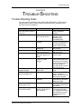
Chapter 8: Trouble-Shooting. Contains the Trouble-shooting Index,
maintenance and service information, and MIDI implementation chart.
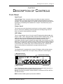
Conventions
The buttons, knobs, and rear panel connectors are referred to in this manual just as
their names appear on the QuadraVerb 2, using all capital letters and in brackets
(Examples: [PROGRAM] button, [< BLOCK] button, [VALUE/ENTER] knob/button,
[DIGITAL IN] connector, etc.).
J
When something important appears in the manual, an icon (like the one on the left)
will appear in the left margin. This symbol indicates that this information is vital when
operating the QuadraVerb 2.
QuadraVerb 2 Reference Manual
1
2
QuadraVerb 2 Reference Manual
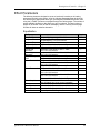
Contents
CONTENTS
1: Setting Up..................................................................................................................7
Unpacking and Inspection .......................................................................................7
AC Power Hookup ..................................................................................................7
Line Conditioners and Protectors ................................................................7
Audio Connections.................................................................................................8
Typical Applications ....................................................................................8
Interfacing Directly with Instruments .............................................................9
Interfacing to a Mixing Console ....................................................................10
Avoiding Ground Loops..............................................................................15
MIDI .......................................................................................................................16
Alesis Optical..........................................................................................................16
Footswitches.......................................................................................................... 16
Advance ....................................................................................................17
Bypass.......................................................................................................17
Tap Tempo.................................................................................................17
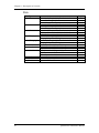
2: Your First Session With The QuadraVerb 2 ........................................................19
Powering Up ..........................................................................................................19
Setting Levels........................................................................................................19
The Value/Enter Knob............................................................................................20
Adjusting the Display Contrast .....................................................................20
Auditioning Internal Programs..................................................................................21
Switching Between Preset and User Banks ..................................................21
Example Programs..................................................................................................22
96: “VerbOfMyDreams”...............................................................................22
97: “Guitar Rack ”.......................................................................................22
98: “Stereo Plates”.....................................................................................22
Adjusting Effects Levels .........................................................................................23
Comparing an Edited Program to its Original Settings................................................24
Restoring an Edited Program to its Original Settings..................................................24
Storing Edited Programs .........................................................................................25
Bypassing Effects...................................................................................................26
Global Direct Signal Muting......................................................................................26
3: Overview ....................................................................................................................27
The Architecture of the QuadraVerb 2......................................................................27
What is a Block?..........................................................................................27
Selecting and Editing Blocks .......................................................................27
Routing “Patch Cords” Between Blocks .......................................................28
Setting the Routing Levels..........................................................................29
The LR IN ...................................................................................................29
Reaching the Outputs - LR OUT ..................................................................29
Limit Handling.........................................................................................................30
Equalization ...........................................................................................................32
Filters.........................................................................................................32
Shelving EQs.............................................................................................33
Single Band EQs........................................................................................33
Multiband EQs............................................................................................34
5 Band Graphic EQ .....................................................................................34
Resonator..................................................................................................35
Mono/Stereo Tremolo.................................................................................35
Stereo Simulator.........................................................................................35
Pitch Effects...........................................................................................................36
Mono Chorus .............................................................................................36
QuadraVerb 2 Reference Manual
3
Contents
Stereo Chorus............................................................................................36
Quad Chorus..............................................................................................37
Mono Flanging ...........................................................................................37
Stereo Flanging..........................................................................................37
Phasor .......................................................................................................38
Mono/Stereo Lezlie Cabinet........................................................................38
Pitch Shifter ...............................................................................................38
Pitch Detune ..............................................................................................38
Ring Modulator...........................................................................................38
Delay .....................................................................................................................39
Mono Delay and Stereo Delay......................................................................39
Ping Pong Delay......................................................................................... 39
Multi Tap Delay ...........................................................................................39
Tap Tempo Mono Delay and Ping Pong .......................................................39
Reverberation ........................................................................................................40
Mono Room ...............................................................................................40
Room 1......................................................................................................40
Hall 1..........................................................................................................40
Plate 1 .......................................................................................................40
Chamber 1 .................................................................................................40
Room 2......................................................................................................40
Hall 2..........................................................................................................40
Plate 2 .......................................................................................................41
Chamber 2 .................................................................................................41
Large Plate.................................................................................................41
Large Room ...............................................................................................41
Spring........................................................................................................41
Nonlinear ...................................................................................................41
Reverse..................................................................................................... 41
Reverb Parameters.................................................................................................42
Decay ........................................................................................................42
Damping – Hi & Lo ......................................................................................42
Reverb Density...........................................................................................42
Diffusion .................................................................................................... 42
Input High Frequency Roll Off...................................................................... 43
Predelay ....................................................................................................43
Predelay Mix...............................................................................................43
Reflection Level and Spread .......................................................................43
Reverberation Swirl..................................................................................... 43
Reverberation Attack ..................................................................................43
Gating........................................................................................................44
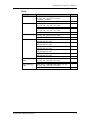
4: Making Your Own Programs ..................................................................................45
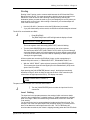
Getting Started .......................................................................................................45
Programming A Single Block ...................................................................................46
Type.......................................................................................................... 46
Routing......................................................................................................47
Parameter ..................................................................................................49
Mix.............................................................................................................50
Programming Multiple Blocks...................................................................................51
Defining New Blocks...................................................................................51
Deleting Unnecessary Routings ..................................................................51
Patching In The New Blocks ........................................................................52
Adjusting Parameters..................................................................................53
Moving and Swapping Blocks..................................................................................53
Changing Effect Types ...........................................................................................54
5: Description of Controls............................................................................................57
Front Panel ............................................................................................................57
4
QuadraVerb 2 Reference Manual
Contents
Input Level .................................................................................................57
Output Level ..............................................................................................57
LED Meter..................................................................................................57
Display.......................................................................................................57
Value/Enter................................................................................................58
Program .....................................................................................................59
Store .........................................................................................................60
Compare ....................................................................................................60
Bypass.......................................................................................................60
< Block > ....................................................................................................60
< Page > ....................................................................................................61
Type.......................................................................................................... 61
Parameter ..................................................................................................61
Routing......................................................................................................61
Mix.............................................................................................................62
Global ........................................................................................................62
Name.........................................................................................................64
MIDI ...........................................................................................................64
Modulation................................................................................................. 66
Power........................................................................................................67
Rear Panel .............................................................................................................67
Power........................................................................................................67
MIDI In ........................................................................................................67
MIDI Thru/Out.............................................................................................67
Bypass.........................- Bypass Footswitch ............................................... 67
Advance ......................- Program Advance Footswitch ............................... 67
48kHz in.......................- Sample Clock Input .............................................. 67
Digital In .......................- Digital Audio In ..................................................... 68
Digital Out ....................- Digital Audio Out .................................................. 68
Left/Right In .................- Analog Audio In ................................................... 68
Left/Right Out ..............- Analog Audio Out ................................................ 68
Effect Parameters...................................................................................................69
Equalization ...............................................................................................69
Pitch..........................................................................................................70
Delay .........................................................................................................71
Reverberation ............................................................................................72
6: Advanced Applications............................................................................................75
MIDI Functions........................................................................................................75
Global MIDI Channel....................................................................................75
Receiving Program Changes .......................................................................75
Program Change Table ...............................................................................76
SysEx Storage ...........................................................................................77
MIDI Thru....................................................................................................78
Realtime Modulation Functions................................................................................ 78
Selecting the Modulator..............................................................................79
Choosing a Target ......................................................................................79
Choosing a Source.....................................................................................81
Setting the Amplitude .................................................................................82
Local Generators ........................................................................................82
Footswitch Controls ................................................................................................85
Program Advance.......................................................................................85
Bypassing Effects.......................................................................................86
Controlling Delay Time via Tap Tempo..........................................................86
7: Alesis Optical Interface............................................................................................87
Overview................................................................................................................87
Digital Clock Synchronization...................................................................................87
Connections .......................................................................................................... 88
QuadraVerb 2 Reference Manual
5
Contents
To a Single ADAT .......................................................................................88
To Two or More ADATs ...............................................................................89
To the AI-1 .................................................................................................91
From the QuadraSynth................................................................................91
Routings................................................................................................................92
To specific ADAT tracks...............................................................................92
From ADAT through the QuadraVerb 2 back to ADAT ...................................93
From the QuadraSynth through the QuadraVerb 2 back to ADAT...................94
8: Trouble-Shooting .....................................................................................................95
Trouble-Shooting Index..........................................................................................95
Error Messages ......................................................................................................96
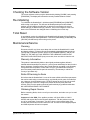
Checking the Software Version ...............................................................................97
Re-initializing..........................................................................................................97
Total Reset.............................................................................................................97
Maintenance/Service ..............................................................................................97
Cleaning ....................................................................................................97
Warranty Information ...................................................................................97
Refer All Servicing To Alesis........................................................................97
Obtaining Repair Service.............................................................................98
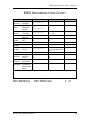
MIDI Implementation Chart .........................................................................................99
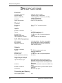
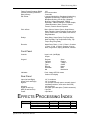
Specifications................................................................................................................100
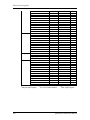
Effects Processing Index .............................................................................................102
6
QuadraVerb 2 Reference Manual
Setting Up - Chapter 1
CHAPTER 1
SETTING UP
Unpacking and Inspection
Your QuadraVerb 2 was packed carefully at the factory, and the shipping carton was
designed to protect the unit during shipping. Please retain this container in the highly
unlikely event that you need to return the QuadraVerb 2 for servicing.
The shipping carton should contain the following items:
•
•
•
•
J
This instruction manual
Alesis QuadraVerb 2 with the same serial number as shown on shipping carton
AC Power Supply Adapter
Alesis warranty card
It is important to register your purchase; if you have not already filled out your warranty
card and mailed it back to Alesis, please take the time to do so now.
AC Power Hookup
The QuadraVerb 2 comes with a power adapter suitable for the voltage of the country
it is shipped to (either 110 or 220V, 50 or 60 Hz).
With the QuadraVerb 2 off, plug the small end of the power adapter cord into
QuadraVerb 2’s [POWER] socket and the male (plug) end into a source of AC power.
It’s good practice to not turn the QuadraVerb 2 on until all other cables are hooked up.
J
Alesis cannot be responsible for problems caused by using the QuadraVerb 2 or any
associated equipment with improper AC wiring.
Line Conditioners and Protectors
Although the QuadraVerb 2 is designed to tolerate typical voltage variations, in
today’s world the voltage coming from the AC line may contain spikes or transients
that can possibly stress your gear and, over time, cause a failure. There are three main
ways to protect against this, listed in ascending order of cost and complexity:
•
Line spike/surge protectors. Relatively inexpensive, these are designed to
protect against strong surges and spikes, acting somewhat like fuses in that they
need to be replaced if they’ve been hit by an extremely strong spike.
•
Line filters. These generally combine spike/surge protection with filters that
remove some line noise (dimmer hash, transients from other appliances, etc.).
•
Uninterruptible power supply (UPS). This is the most sophisticated option. A UPS
provides power even if the AC power line fails completely. Intended for computer
applications, a UPS allows you to complete an orderly shutdown of a computer
system in the event of a power outage, and the isolation it provides from the
power line minimizes all forms of interference—spikes, noise, etc.
Audio Connections
The connections between the QuadraVerb 2 and your studio are your music’s lifeline,
so use only high quality cables. These should be low-capacitance shielded cables
with a stranded (not solid) internal conductor and a low-resistance shield. Although
QuadraVerb 2 Reference Manual
7
Chapter 1 - Setting Up
quality cables cost more, they do make a difference. Route cables to the QuadraVerb
2 correctly by observing the following precautions:
•
Do not bundle audio cables with AC power cords.
•
Avoid running audio cables near sources of electromagnetic interference such as
transformers, monitors, computers, etc.
•
Do not place cables where they can be stepped on. Stepping on a cable may not
cause immediate damage, but it can compress the insulation between the center
conductor and shield (degrading performance) or reduce the cable’s reliability.
•
Avoid twisting the cable or having it make sharp, right angle turns.
•
Never unplug a cable by pulling on the wire itself. Always unplug by firmly
grasping the body of the plug and pulling directly outward.
•
Although Alesis does not endorse any specific product, chemicals such as
Tweek and Cramolin, when applied to electrical connectors, are claimed to
improve the electrical contact between connectors.
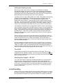
Typical Applications
The analog audio inputs and outputs are typically used in one of three ways:
•
from one or two effect/aux send outputs of a mixer, and out to the effect return
inputs of the mixer; or,
•
from a line-level instrument (like a guitar or keyboard with either a mono or stereo
output), and out to an amplifier or mixer input; or,
•
from the stereo buss outputs of a mixer to a mix-down tape machine or amplifier.
When used with a mono source, the QuadraVerb is placed between the source and
the mixer/amplifier. Although the source may be mono, both the [LEFT] and [RIGHT]
outputs can be connected to the inputs of a mixer/amplifier if stereo processing
effects are desired. Alternatively, you could use the INSERTS on your mixer to “patch
in” only the left or right channel of the QuadraVerb 2. If using the effect sends of a
mixer, you have the advantage of sending any of the mixer’s input channels to the
QuadraVerb 2’s input(s), and have control over the level of each channel being sent.
There are other combinations of input and outputs possible when you begin using
the Alesis optical digital input and output. See the “Alesis Optical” section later in this
chapter. For more information on interfacing with other digital audio equipment, see
chapter 7.
Interfacing Directly with Instruments
J
When connecting audio cables and/or turning power on and off, make sure that all
devices in your system are turned off and the volume controls are turned down.
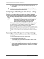
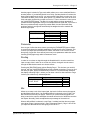
The QuadraVerb 2 has two 1/4” balanced inputs and two 1/4” balanced outputs.
These provide three different (analog) audio hookup options:
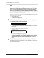
•
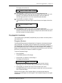
8
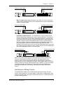
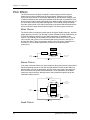
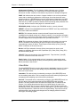
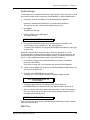
Mono. Connect a cable to the [R] INPUT of the QuadraVerb 2 from a mono
source, and another cable from the [R] OUTPUT of the QuadraVerb 2 to an
amplification system or mixer input.
QuadraVerb 2 Reference Manual
Setting Up - Chapter 1
Instrument or Effect Send
To Amplifier or Mixing Console
Right
Input
Right
Output
TM
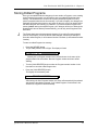
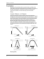
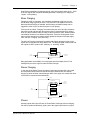
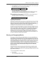
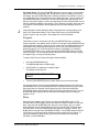
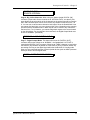
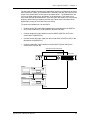
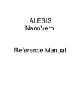
•
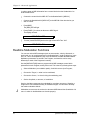
Mono In, Stereo Out. While still using a mono input, you could connect two
cables to the [L] and [R] OUTPUTS of the QuadraVerb 2 to a stereo amplification
system or two mixer inputs.
Instrument or Effect Send
To Amplifier or Mixing Console
Right
Input
Right
Output
Left
Output
TM
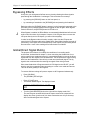
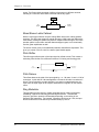
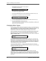
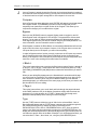
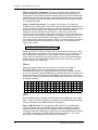
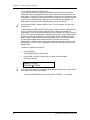
•
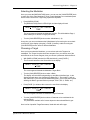
Dual Mono or Stereo Source. The QuadraVerb 2 may be used with two
different instruments simultaneously, or with a stereo instrument. The hookup is
the same; the difference is in the routing used within a program. A program may
process the two inputs discretely, using blocks dedicated to a single channel (for
example, a delay for a guitar and a gated reverb for a bass), or process them in
stereo (for example, with the left and right outputs of a keyboard routed through
two reverb blocks). Connect two cables to the [L] and [R] INPUTS of the
QuadraVerb 2 from two mono sources or from the stereo output of the instrument,
then connect two other cables from the [L] and [R] OUTPUTS of the QuadraVerb 2
to a stereo amplification system or two mixer inputs.
To Amplifier or Mixing Console
Instrument or Effect Send
Left Input
Right
Input
Right
Output
Left
Output
BLOCK
TM
2
7
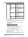
Note: In most cases when plugging an instrument directly into the QuadraVerb 2 ,
you’ll use Programs which route the "dry" signal at the input(s) directly to the
output(s), where it will be mixed together with the effected signal to achieve the
proper wet/dry mix at the QuadraVerb 2's outputs. If the program doesn't include this
routing, you will only hear the effected signal by itself. Therefore, it may be necessary
to edit such programs to add these "dry" routes when using the QuadraVerb 2
directly with an instrument. (The Factory Preset programs usually include these
routes.)
Interfacing to a Mixing Console
The QuadraVerb 2 handles mono or stereo sends at all system levels. The input
circuitry of the QuadraVerb 2 can easily handle +4 dBu levels (+19 dBu peaks), while
having enough input and output gain to interface with the lower -10 dBV signal levels
of many recording systems.
QuadraVerb 2 Reference Manual
9
Chapter 1 - Setting Up
The QuadraVerb 2 may be connected to a mixing console in several ways. Usually, it
is connected to the auxiliary send and return controls of the mixer. Another method of
interfacing is to connect the unit directly to the insert send and return patch points of
the channel that is to be effected. Still another way of interfacing the QuadraVerb 2 to
a mixer or recording console would be in-line across the output of your mixing
console. This last setup would be used only if you needed to effect the entire mix.
Using the Aux Sends
Generally, mixing consoles provide two types of auxiliary sends: pre-fader sends for
creating a cue (headphone) mix, and individual, post-fader effect sends. Typically, if a
mixer has more than two sends per channel (4, 6 or 8, perhaps), the first two sends
are reserved for the cue sends, while the remaining sends are used to feed effects. If
you are using a mixer with more than two sends, connect the QuadraVerb 2 using
post-fader sends.
Using a mixer’s aux sends poses a distinct advantage: each channel has its own level
control feeding the aux output (and eventually the QuadraVerb 2 input). This allows
you to make a mix of any channels you want to go to the effects by using the
individual channels’ aux send levels on the mixer. Most consoles also have aux
master controls, which set the overall level of each aux output.
Coming back from the QuadraVerb 2’s outputs into the mixer, you have two options:
•
connecting to dedicated return inputs, or
•
connecting to channel inputs.
The former is good if your mixer provides dedicated inputs (called returns) for effect
devices like the QuadraVerb 2. If your mixer does not have these, or you have already
used them all, consider connecting the QuadraVerb 2 to channel inputs or unused
tape returns.
Setting the Effect/Dry Balance
No matter where you connect the output of the QuadraVerb 2 into the mixer, you are
in control of the balance between the mixer’s channel inputs (the uneffected signal
being routed to the aux sends and the Mix) and the effect returns coming from the
QuadraVerb 2. The effect returns generally should only contain effected signal, and
not have any uneffected signal mixed with it (since these two signals are blended
together at the mixer).
If the Program you are using has the LR IN connected to the LR OUT, you may be
getting some dry, uneffected signal at the return. Generally, this is not desirable,
since the "dry" signal is already being heard through the original channel’s fader.
Therefore, in a mixer application you will want to cut the QuadraVerb 2’s Program’s
path which connects the inputs to the outputs. This can be done in three ways:
10
•
Go to the Mix parameters to bring down the direct level
•
Go to the Routing function of each program and remove the patch cords
connecting the inputs to the outputs
•
Turn on the Global Direct Signal Mute function. This is the easiest method.
QuadraVerb 2 Reference Manual
Setting Up - Chapter 1
J
Most Preset Programs route the LR IN signal to the LR OUT.When connecting to a
mixer’s aux sends and returns. the Global Direct Signal Mute should be set to ON.
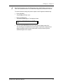
To remove all direct routings of inputs to outputs on all Programs simultaneously:
¿ Press [GLOBAL].
The [GLOBAL] LED will be lit.
¡
Press [< PAGE] once.
This selects Global Page 9. The display will read:
GLOBAL DIRECT SIGNAL MUTE:
OFF
¬ Turn the [VALUE/ENTER] knob to the right until the display reads “ON.”
The next Program recalled which has the inputs routed to the outputs will not
display the patch cords for these connections nor will you hear any direct
uneffected signal at the outputs.
QuadraVerb 2 Reference Manual
11
Chapter 1 - Setting Up
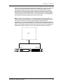
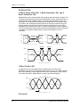
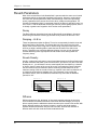
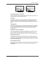
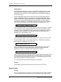
Mono In - Stereo Out. If you only want to feed the QuadraVerb 2 a mono input,
but wish to connect both of its outputs back to the mixer, you will need three 1/4"
audio cables. Connect a cable from an effect send to the [R] INPUT of the
QuadraVerb 2, another cable from the [L] OUTPUT of the QuadraVerb 2 to an effect
return or other mixer input, and another cable from the [R] OUTPUT of the
QuadraVerb 2 to an adjacent mixer input.
Right Input
Left Output
Right Output
Aux Send 1
Aux Return or Input Channel
Aux Return or Input Channel
Mixer
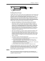
Stereo In - Stereo Out. This connection is similar to the one described above.
However, by utilizing two sends from the mixer, we add one more cord and can now
send a stereo signal to the QuadraVerb 2’s inputs. Example, if you connected effect
sends 3 and 4 to the [L] and [R] INPUTS, and had a stereo instrument (such as a
keyboard) connected to two channel inputs of the mixer (either one panned hard left
and hard right), you would send the left channel to send 3 and the right channel to
send 4. Alternatively, you could have two discrete effect sends between the Left and
Right channel, and process each separately within the QuadraVerb 2. For example,
the Left channel (from send 3) could be a chorus, and the Right (from send 4) could be
a reverb. This is similar to Dual Mono, described earlier.
Right Input
Left Input
Left Output
Aux Send 3
Right Output
Aux Send 4
Aux Return or Input Channel
Aux Return or Input Channel
Mixer
Using Inserts
By using individual channel inserts, you can dedicate the QuadraVerb 2 to a specific
channel (or pair of channels) on the mixer. The Insert connections on the back of the
mixer provide a way of “inserting” external processing equipment into the signal path.
The insert occurs after the input amplifier, and before the main fader; essentially it is
the same as connecting the source (instrument or microphone) into the QuadraVerb
2 before the mixer’s channel input. However, some mixing console’s inserts come
after the EQ section, and may therefore be different from the original signal.
12
QuadraVerb 2 Reference Manual
Setting Up - Chapter 1
Usually, insert connections require a special, stereo-splitting Y-cord to be connected
(one stereo plug provides both send and return while two mono plugs connect
separately to an input and output). These are known as TRS connectors (tip-ringsleeve). The tip of the stereo plug typically carries the send or output of the insert
jack, while the ring carries back the return. The sleeve represents a common ground
for both signals. Check the manual of your mixer because some are wired differently
(for example, having two separate jacks for send and receive).
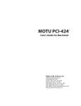
Mono. This involves connecting a 1/4" TRS (tip-ring-sleeve) to the Insert jack of a
single channel on a mixing console. The other end of the cable (which splits into two,
1/4" mono connectors) are connected to the [R] INPUT and [R] OUTPUT,
respectively. If you do not hear any audio after making these connections, swap the
input and output cables at the QuadraVerb 2, as these may be wired backwards. If the
cable is color-coded, usually the red jack represents the send (which connects to the
QuadraVerb 2’s INPUT) and black is the return (which connects to the OUTPUT).
MIXER
Insert
Right Input
Right Output
3
QuadraVerb 2 Reference Manual
13
Chapter 1 - Setting Up
Stereo. In the case where a stereo instrument, such as a keyboard or sampler, is
connected to two separate channels of a mixing console, you will need two 1/4" TRS
cables, one for each channel. The connection is made in a similar fashion as
described above.
MIXER
Right
Master
Insert
Left
Master
Insert
Left Input
Left Output
Right Input
Right Output
Using Main Outputs
When you want to effect everything on the mixer, you can connect the QuadraVerb 2
between the mixer’s outputs and the amplifier’s or tape machine’s inputs. This is done
by using two 1/4" cables to connect the Left and Right Main Outputs of the mixing
console to the [L] and [R] INPUTs of the QuadraVerb 2. The [L] and [R] OUTPUTs of
the QuadraVerb 2 are then connected to a stereo amplifier, or two input channels of
another mixing console (for sub-mixing applications).
Right Input
Left Input
Left
Master
Out
Left Output
Right Output
Left Input
Right Input
Right
Master
Out
Mixer
Stereo Amp
If your mixer’s outputs use XLR balanced connectors, use the illustration below as a
guide for wiring cables to connect to the QuadraVerb 2’s inputs.
14
QuadraVerb 2 Reference Manual
Setting Up - Chapter 1
Tip
2
1
Sleeve
3
Ring
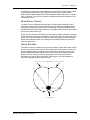
Avoiding Ground Loops
In today’s studio, where it seems every piece of equipment has its own computer chip
inside, there are many opportunities for ground loop problems to occur. These show
up as hums, buzzes or sometimes radio reception, and can occur if a piece of
equipment “sees” two or more different paths to ground. While there are methods to
virtually eliminate ground loops and stray radio frequency interference, most of the
professional methods are expensive and involve installing a separate power source
just for the sound system. Here are some easy helpful hints that a professional studio
installer might use to keep those stray hums and buzzes to a minimum.
¿ KEEP ALL ELECTRONICS OF THE SOUND SYSTEM ON THE SAME AC
ELECTRICAL CIRCUIT. Most stray hums and buzzes happen as a result of
different parts of the sound system being plugged into outlets of different AC
circuits. If any noise generating devices such as air conditioners, refrigerators,
neon lights, etc., are already plugged into one of these circuits, you then have a
perfect condition for stray buzzes. Since most electronic devices of a sound
system don’t require a lot of current (except power amplifiers), it’s usually safe to
run a multi-outlet box (or two) from a SINGLE wall outlet, and plug in all of the
components of your system there.
¡
KEEP AUDIO WIRING AS FAR AWAY FROM AC WIRING AS POSSIBLE. Many
hums come from audio cabling being too near AC wiring. If a hum occurs, try
moving the audio wiring around to see if the hum ceases or diminishes. If it’s not
possible to separate the audio and AC wiring in some instances, make sure that
the audio wires don’t run parallel to any AC wire (they should only cross at right
angles, if possible).
¬ TO ELIMINATE HUM IF THE ABOVE HAS FAILED:
A) Disconnect the power from all outboard devices and tape machines except
for the mixer and control room monitor power amp.
B) Plug in each tape machine and outboard effects device one at a time. If
possible, flip the polarity of the plug of each device (turn it around in the
socket) until the quietest position is found.
C) Make sure that all of the audio cables are in good working order. Cables with a
detached ground wire will cause a very loud hum!!
D) Keep all cables as short as possible, especially in unbalanced circuits.
If the basic experiments don’t uncover the source of the problem, consult your dealer
or technician trained in proper studio grounding techniques. In some cases, a “star
grounding” scheme must be used, with the mixer at the center of the star providing
the shield ground on telescoping shields, which do NOT connect to the chassis
ground of other equipment in the system.
MIDI
MIDI is an internationally-accepted protocol that allows music-related data to be
conveyed from one device to another. The MIDI connections on the QuadraVerb 2
provide four different functions:
QuadraVerb 2 Reference Manual
15
Chapter 1 - Setting Up
•
To recall programs using MIDI program change messages
•
To control various parameters inside the QuadraVerb 2 in realtime via MIDI
controllers (example: A keyboard’s mod wheel, or pedals, etc.)
•
To send and receive SysEx (System Exclusive) dumps of individual programs or
the entire bank of programs for storage and retrieval purposes
•
To pass-on MIDI information thru the QuadraVerb 2 to another MIDI device.
To connect the QuadraVerb 2’s MIDI ports to another MIDI device:
¿ Connect a MIDI cable from the QuadraVerb 2’s MIDI [THRU/OUT] connector to the
MIDI IN connector of the other MIDI device.
¡
Connect another MIDI cable from the QuadraVerb 2’s MIDI [IN] connector to the
other MIDI device’s MIDI OUT connector.
For more information about MIDI, refer to chapter 6.
Alesis Optical
The Alesis Optical interface provides two EIAJ fiber optic connectors for [DIG IN] and
[DIG OUT]. These connectors use a proprietary Alesis multichannel format first
introduced with the ADAT Multitrack Recorder. The QuadraVerb 2 can send and/or
receive digital audio directly to/from an ADAT (or other devices which use the same
optical interface). Digital connections provide better fidelity than the analog inputs
and outputs.
The proprietary Alesis Optical format carries up to 8 audio channels on a single fiber
optic cable. Since the QuadraVerb 2 has two channels (left and right), you may
choose two of the incoming 8 channels for the QuadraVerb 2 to process. The
QuadraVerb 2’s Left and Right Outputs can then be routed in the digital format using
any two channels (they don’t have to be the same as the input channels). Fiber optic
cables of various lengths are available from your Alesis dealer. The shorter the cable,
the better. The OC cable is 5 meters long (16'4") and is the maximum length
recommended.
Footswitches
On the rear panel you will find two footswitch jacks labeled [ADVANCE] and
[BYPASS]. Any momentary single-pole/single-throw footswitch, normally open or
normally closed, will work for the two footswitch functions. These should be plugged
in prior to power-up so that the QuadraVerb 2 can configure itself for the type of
footswitch being used.
Advance
The [ADVANCE] jack lets you scroll through the Programs in memory by advancing to
the next higher numbered Program each time the connected footswitch is pressed.
The QuadraVerb 2 will “wrap-around” whenever it reaches the end of available
Programs and the Advance footswitch is pressed again. You can set a range of
Programs to be used, thereby cutting off other Programs from being recalled in this
manner. For example, if you set the range to be User 10 through User 24, only
Programs within this range will be recalled using the Advance footswitch. If Program
24 is selected and the footswitch is pressed again, Program 10 is recalled.
16
QuadraVerb 2 Reference Manual
Setting Up - Chapter 1
To adjust the Advance Footswitch’s set of Programs:
¿ Press [GLOBAL].
The [GLOBAL] LED will light.
¡
Press [PAGE >] once.
This selects page 2, and the display will read:
FOOTSWITCH: 00 Pset TO 00 Pset
¬ Turn the [VALUE/ENTER] knob to adjust the Program number to begin the range
(Preset 00 — 99, User 00 — 99).
÷ Press [PAGE >] once and use the [VALUE/ENTER] knob to adjust the Program
number to end the range (Preset 00 — 99, User 00 — 99).
Bypass
The Bypass footswitch jack lets you turn the Bypass function on and off from a
connected footswitch. When pressed, the [BYPASS] LED will light, indicating that
Bypass mode is enabled. When pressed again, the [BYPASS] LED will turn off.
For more information about Bypass mode, see chapters 2 and 5.
Tap Tempo
Either footswitch jack can be used to provide a tap tempo source for setting delay
time, provided the selected Program uses one of the two available tap tempo delay
types. This requires that you have defined an Effect Block as one of the two Tap
Tempo delay types, and that the desired footswitch jack has been selected for
controlling tap tempo. To select a footswitch jack for use with a Tap Tempo Delay:
¿ Press [GLOBAL].
The [GLOBAL] LED will light.
¡
Press [< PAGE] twice to select Global Page 8.
The display will read:
TAP TEMPO FOOTSWITCH: NONE
¬ Turn the [VALUE/ENTER] knob to select either the ADVANCE or BYPASS
footswitch jack, depending on which one you wish to use to control tap tempo.
QuadraVerb 2 Reference Manual
17
18
QuadraVerb 2 Reference Manual
Your First Session With The QuadraVerb 2 - Chapter 2
CHAPTER 2
YOUR FIRST SESSION WITH THE
QUADRAVERB 2
Powering Up
After making your connections, turn on the system’s power using this procedure:
¿ Before turning on the QuadraVerb 2’s power, check the following items:
•
•
¡
Have all connections been made correctly?
Are the volume controls of the amplifier or mixer turned down?
Turn on the [POWER] switch on the front panel of the QuadraVerb 2.
Upon power-up, the QuadraVerb 2 will display the last selected Program, and the
[PROGRAM] button’s LED will be lit. If this Program has been edited, the display
will indicate this by showing the word “EDITED”, and by flashing the Program
Number and Name in the upper display.
¬ Turn on the power of the amplifier/mixer, and adjust the volume.
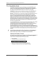
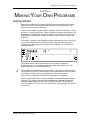
Setting Levels
Proper setting of the [INPUT LEVEL] and [OUTPUT] knobs is crucial in order to
achieve the maximum signal-to-noise ratio (the concentric knobs allow the Left and
Right Input levels to be adjusted separately). As a good starting point, set both input
and output level controls at about 2 o'clock or 65% of full. This will decrease the
possibility of overload distortion and keep the amount of background noise to a
minimum.
J
For quietest operation, you should adjust the level of the source being sent to the
QuadraVerb 2 so that the green [-3dB] LEDs in the QuadraVerb 2’s peak meter flash,
but not so loud that the red [CLIP] LEDs turn on. A nominal input sound make the
-12dB LED turn on
QuadraVerb 2 Reference Manual
19
Chapter 2 -Your First Session With The QuadraVerb 2
The Value/Enter Knob
Located just to the right of the custom LCD display, the [VALUE/ENTER] knob is
used to select Programs and adjust parameter values that appear in the display.
However, it is not just a knob, it is also a button. Depending on what parameter you
are editing, the [VALUE/ENTER] knob will work in either one of two ways:
Immediate. The desired value is selected by turning the [VALUE/ENTER] knob,
and immediately takes effect. This is the case when adjusting most parameters.
Deferred. The desired value is selected by turning the [VALUE/ENTER] knob, but
the new value will only take effect after the [VALUE/ENTER] button has been
pressed. The newly selected value will flash in the display until it is selected in this
manner. If you change the parameter back to its original setting, the value in the
display will not flash. Also, if you go to another Page, or select another Function (by
pressing any button), the parameter will be left unchanged. If you went back to look at
the previous parameter, it will be set back to its original setting. This mode is used for
parameters that cause architectural changes such as changing a Block’s function,
effect type, and routing signals.
The [VALUE/ENTER] button can also be used to step through Pages in the currently
selected mode. Except when a value is flashing on and off in the display, the
[VALUE/ENTER] button ordinarily doubles for the [PAGE >] button. If you change
the value of a parameter that uses “deferred mode,”, you must press the
[VALUE/ENTER] button to enter the new value (the display will stop flashing), and
then you can press it again to move to the next Page (or to the next parameter, if more
than one parameter appears in the display). This is a feature for power users who want
to be able to move around the various pages quickly and make changes as fast as
possible.
J
Unique Exception: When editing the Delay Time parameter of a Delay Block set to
either Tap Tempo Mono Delay or Tap Tempo Ping Pong, the [VALUE/ENTER]
button is used to “tap” in a tempo . See chapter 6 for more information.
Adjusting the Display Contrast
Occasionally, the characters in the LCD display may be difficult to read, depending on
the viewing angle and existing lighting conditions. In such a situation, adjust the
contrast of the LCD display using the following procedure.
¿ Press [GLOBAL].
The display will go to the Global Mode Page 1.
ADJUST DISPLAY CONTRAST: 5
¡
20
Adjust the contrast by turning the [VALUE/ENTER] knob.
The display’s contrast and its value in the display will change.
QuadraVerb 2 Reference Manual
Your First Session With The QuadraVerb 2 - Chapter 2
Auditioning Internal Programs
You can audition the Programs in the QuadraVerb 2 by using the [VALUE/ENTER]
knob or the front panel buttons, whenever the QuadraVerb 2 is in Program mode (the
[PROGRAM] button’s LED will be lit).
To select a Program using the [VALUE/ENTER] knob:
¿ Press [PROGRAM].
The [PROGRAM] button’s LED will light.
¡
Turn the [VALUE/ENTER] knob.
Note: The [VALUE/ENTER] knob has two modes when used for selecting Programs:
Direct and Deferred. Direct mode immediately recalls the displayed Program as you
turn the [VALUE/ENTER] knob. Deferred mode lets you scroll through the Programs
in the display by turning the [VALUE/ENTER] knob, but you must press the
[VALUE/ENTER] button to actually recall a Program. For more information on
choosing between Direct and Deferred mode, see chapter 5.
To select a Program using the front panel buttons:
¿ Hold the [PROGRAM] button.
¡
Use the [1] through [0] buttons to directly select Programs 00 through 99.
These are the right-most ten buttons on the front panel, which double for
[BLOCK >], [TYPE], [ROUTING], etc.
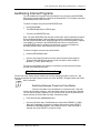
The top line of the display will change to indicate the currently selected Program
number (from 00-99) and its name.
PROGRAM: 00 "More Divisions"
The left side of the display always indicates the currently selected Program number (00 – 99).
Directly beneath the two-digit Program number, the word “PRESET” will appear when the Preset
PROGRAM
bank is selected.
Switching Between Preset and User Banks
PRESET
There are two banks in the QuadraVerb 2: Preset and User. They both
contain 100 Programs. However, the Preset bank cannot be permanently changed.
You can edit the Preset Programs, but you can store them only in the User bank. To
switch between the Preset and User bank, follow these steps:
¿ Press and hold the [PROGRAM] button.
¡
Use the [< BLOCK] and [< PAGE] buttons to select either PRESET or USER.
When the Preset bank is selected, the display will show the word “PRESET”
beneath the PROGRAM Number in the lower left corner. If the User bank is
selected, the word “PRESET” will not be visible.
QuadraVerb 2 Reference Manual
21
Chapter 2 -Your First Session With The QuadraVerb 2
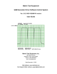
Example Programs
The following are descriptions of the three example Programs in the Preset bank.
96: “VerbOfMyDreams”
This Program is fairly simple in design, using only 3 Blocks to provide EQ, Delay and
Reverb. It is designed for a mono audio source to be connected to the [R] INPUT. In
the display, you can see the R IN routed to the first Block, which is defined as a 3Band Parametric EQ. The M output of the EQ then is routed to the next Block, which
is a Mono Delay. The M output of the Delay is then routed to the next Block, which is a
Room 2 Reverb. The L output of the Reverb is routed to the L OUT while the R
output of the Reverb is routed to the R OUT. Also, the R IN is routed to both the L and
R OUT, to combine the original dry signal with the wet signal coming from Block #3.
The EQ Block is used to tailor the sound before further processing occurs. You
should make adjustments here based on the signal you feed through it; if the higher
frequencies of the input signal do not sound as good through the Reverb as the mids
and lows, try attenuating them in the EQ. The Delay is used to “thicken” the sound by
adding a few very fast echoes. The Reverb adds ambiance, as if you were in a large
chamber, and completes the total effect.
Using the Mix function, you can adjust the output level of the Reverb Block and the
Direct Signal to create the balance you are looking for.
97: “Guitar Rack”
This Program includes two Pitch Blocks feeding a delay Block, into another Pitch Block,
then into a Reverb Block, and finally yet another Pitch Block. This is a prime example of the
flexibility the QuadraVerb 2 offers to programmers. The Program creates a thick, swirling,
ambient effect that greatly enhances an electric guitar’s sound.
The R IN is routed to Blocks 1 and 2, as well as the L and R OUT. The first two Pitch
Blocks are defined as Pitch Detune type, but are set to different detune amounts to
create a thicker sound. The Delay Block is a Mono Delay which provides a very quick
“slap back” by using a small delay time and no feedback. The third Pitch Block
provides a Stereo Chorus which swirls the detuned, delay signal and feeds directly to
the outputs. The Delay Block’s output is also fed into a Hall 1 Reverb which provides
ambience to the un-chorused signal. The Reverb’s stereo signals are routed to the
QuadraVerb 2’s outputs and mixed with the Stereo Chorus’s signals. Meanwhile, the
Reverb’s mono output feeds a Stereo Flanger whose stereo signals are also
combined with the Stereo Chorus, Reverb and the original input signal at the outputs.
Again, use the Mix parameters to create just the balance you want.
98: “Stereo Plates”
This Program is very simple. It routes the L and R IN through separate stereo type
Reverb Blocks (Plate 1 type, to be precise). Both stereo signals coming out of the two
Reverb Blocks feed the LR OUT. This creates a very clean stereo reverb effect that’s
great for vocals. Play around with the Predelay and Decay parameters to adjust the
attack and length of the reverb.
22
QuadraVerb 2 Reference Manual
Your First Session With The QuadraVerb 2 - Chapter 2
Adjusting Effects Levels
Although we may not want to get started editing Programs just yet (that’s left for
chapter 4), it is usually necessary to have immediate control over the output levels of
each Effect Block, as well as the amount of direct level going from the inputs to the
outputs. These are found within Mix mode.
To adjust a Program’s effect levels:
¿ Press the [MIX] button.
The [MIX] button’s LED will light.
¡
Use the [< BLOCK >] buttons to select any of the active Blocks in the display.
If the selected Block is routed to the LR Outputs, the display will read:
LEVEL TO L/R:RVB=100%
The letters RVB in the display example above indicate the selected Block is of the
Reverberation type. Other types are: EQ for Equalization, PCH for Pitch and DLY
for Delay.
¬ Turn the [VALUE/ENTER] knob to adjust the Block’s Level to the LR Outputs,
from 0–100%.
If the selected Block is not routed to the LR Outputs, this setting will be “NONE”
and you will not be able to adjust the value.
÷ Press [PAGE >] to advance to Mix Page 2 and adjust the Direct Level from Input.
The display will read:
DIRECT LEVEL FROM INPUT:
100%
ƒ Turn the [VALUE/ENTER] knob to adjust how much of the dry (uneffected) signal
you wish to hear at the QuadraVerb 2’s outputs, from 0–100%.
If the LR Inputs are not routed to the LR Outputs, this setting will be “NONE” and
you will not be able to adjust the value since there is no direct signal.
J
If the Global Direct Signal Mute function is turned on, the Direct Level From Input
parameter will have no audible effect, although its setting is remembered when you
store the Program.
ª
Press [PAGE >] to advance to Mix Page 3 and adjust the Master Effects Level.
MASTER EFFECTS LEVEL: 100%
D Use the [VALUE/ENTER] knob to adjust the Master Effects Level to the LR
Outputs, from 0–100%.
This parameter comes between the combined Effect Blocks’ outputs and the
QuadraVerb 2’s outputs, and controls the output levels of all active Blocks that
are routed to the LR Outputs simultaneously. However, it does not change the
individual output levels of Effect Blocks that are routed internally (i.e. to other
Blocks).
QuadraVerb 2 Reference Manual
23
Chapter 2 -Your First Session With The QuadraVerb 2
« Use the [< BLOCK >] buttons to select other Blocks, and adjust their levels, as
described above.
J
Mix parameters affect the Program and are only temporary unless the Program is
stored into memory before a another Program is recalled. See later in this chapter for
more about comparing and storing edited Programs.
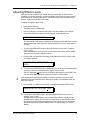
Comparing an Edited Program to its Original Settings
The left side of the display always indicates the currently selected Program. Once a Program has
been edited, the word “EDITED” appears in the lower left part of the display, just below the
Program Number indicator. If the [PROGRAM] button is pressed (the [PROGRAM] button’s LED
will light), the display will also indicate the Program has been altered from its stored
PROGRAM
version by flashing the Program number and name in the upper section of the display.
By pressing [COMPARE], you can temporarily access the original version
of the Program you are editing; that is, the last Program saved to the
currently selected location number. This allows you to hear the
differences created by changing parameters in the Program.
EDITED
While you are in Compare mode, the [COMPARE] button’s LED will be lit. Also, you
cannot adjust any of the Type, Routing, Parameter, Modulation settings. However,
you can move around the various pages and view these original settings and
therefore see the actual differences in settings you have changed.
Pressing [COMPARE] a second time exits Compare mode; the [COMPARE] button’s
LED will turn off and the edited version of the Program will be accessed. You can go in
and out of Compare mode as often as you like, as long as the display indicates
“EDITED” (i.e., if the Program hasn’t been edited yet, there is nothing to compare it
to).
Restoring an Edited Program to its Original Settings
If you decide to abort the changes you have made to a Program, this can be done in
two easy steps.
To restore an edited Program to its previous, unedited version:
¿ Press [PROGRAM] to select Program mode.
The [PROGRAM] button’s LED will light, and the display will flash the selected
Program number and name.
¡
24
Press the [VALUE/ENTER] button.
This recalls the last stored version of the currently selected Program number, and
the word “EDITED” disappears from the display. Consequently, any changes you
had made to the Program before recalling are lost. unless you stored the edited
Program into memory.
QuadraVerb 2 Reference Manual
Your First Session With The QuadraVerb 2 - Chapter 2
Storing Edited Programs
Once you are satisfied with the changes you have made to a Program, or are creating
a new Program from scratch, you will need to store your edited Program back into
memory. The QuadraVerb 2 will store the currently selected Program in memory
(which is retained when the unit is turned off). If you edit a Program, the changes you
made will still be there the next time you switch on the unit, even if you hadn’t stored
the edited Program into memory yet. However, if you select another Program from
memory before storing the edited Program, your changes will be lost. Although the
QuadraVerb 2 has two banks (Preset and User), you can only store Programs in the
User bank.
J
The Preset bank cannot be permanently changed. If you edit a Program selected
from the Preset bank, you will be able to make changes, but when you attempt to
Store the edited Program, it will be stored into the User bank (in the selected number
location).
To store an edited Program into memory:
¿ Press the [STORE] button.
The [STORE] button’s LED will light. The display will read:
STORE AT: XX "nnnnnnnnnnnnnn"
…whereby XX is a Program number from 0 to 99 and nnnn is the name of the
program that will be overwritten. Both the Program number and name will be
flashing.
¡
Turn the [VALUE/ENTER] knob to select the Program number location in the
User bank to store the edited Program into.
¬ Press the [VALUE/ENTER] button.
The display will momentarily read:
PROGRAM STORED
After storing, the User Program location you chose will automatically be selected
and shown in the display (example: if you edited Program 13 and stored it into
location 25, Program 25 will be selected).
QuadraVerb 2 Reference Manual
25
Chapter 2 -Your First Session With The QuadraVerb 2
Bypassing Effects
At any time you can bypass all effects at once, thereby allowing the direct signal to
pass through the QuadraVerb 2 unchanged. This can be done in two ways:
•
by pressing the [BYPASS] button on the front panel; or,
•
by connecting a footswitch to the [BYPASS] jack and pressing the footswitch.
Each time either the [BYPASS] button is pressed, or the footswitch connected to the
[BYPASS] jack is pressed, Bypass mode is toggled on and off again. When Bypass
mode is turned on, the [BYPASS] button's LED will be lit.
J
When Bypass is enabled, all Effect Blocks are momentarily disabled and will not have
audio routed from them to the outputs. However, if the Program does not route the
LR Inputs directly to the LR Outputs, you will not hear anything.
In order for the Bypass mode to function correctly, make sure the LR Inputs are
routed to the LR Outputs and that the Global Direct Signal Mute function is turned off
(see below). If the inputs are not routed directly to the outputs, the [BYPASS] button
acts more like a “mute” since nothing will be heard when it is enabled.
Global Direct Signal Muting
The purpose of this feature is to satisfy the conditions of a recording studio
environment. As described in chapter 1, when connecting the QuadraVerb 2 to a
mixing console’s aux sends and returns, it is generally desirable to remove the direct
signal feed from the outputs of the QuadraVerb 2. This is because the signal coming
back from the QuadraVerb 2 should only contain wet (uneffected) signal. The dry
signal is then combined with the returning wet signal at the mixing console.
Since most QuadraVerb 2 Programs route the LR IN signal to the LR OUT, you will
need to mute this connection when connecting to a mixer’s aux sends and returns.
This can be done globally for all Programs.
To remove all direct routings of inputs to outputs on all Programs simultaneously:
¿ Press [GLOBAL].
The [GLOBAL] LED will light.
¡
Press [< PAGE] once.
This selects Global Page 9. The display will read:
GLOBAL DIRECT SIGNAL MUTE:
OFF
¬ Turn the [VALUE/ENTER] knob to the right until the display reads “ON.”
The next Program recalled which has the inputs routed to the outputs will not
display the routes (“patch cords”) for these connections nor will you hear any
direct uneffected signal at the outputs.
26
QuadraVerb 2 Reference Manual
Overview - Chapter 3
CHAPTER 3
OVERVIEW
The Architecture of the QuadraVerb 2
The QuadraVerb 2 provides eight Effect Blocks per Program, each of which can serve
as either EQ, Pitch, Delay or Reverb. The display shows these Blocks from left to
right, between the LR IN (left and right inputs) and the LR OUT (outputs). The display
also illustrates the routings between the Blocks. In addition to the Block functions,
there is a set of Modulations which may be used in a Program. These allow MIDI
messages (such as note numbers, velocity, after-touch, pitch-bend or controllers) to
serve as controls over parameters in the QuadraVerb 2. This is discussed in further
detail in chapter 6. For now, let’s discuss the essence of Blocks and how they interact
with each other.
What is a Block?
A Block is essentially a discrete effects processor that can be used alone or in
conjunction with other Blocks. Each Block has a Mono input and up to three outputs
(depending on its type): left, right and mix. A Block requires that a signal be routed to
it before it can effect the signal. The Block must also have its output connected either
to the L OUT or R OUT (or both), or to the input of another Block (or to a series of
Blocks) which is in turn connected to either the L OUT or R OUT (or both) before the
Block’s effect can be heard.
The four effect functions available in a Block are: Equalization, Pitch, Delay and
Reverberation. Each one of these has several effect types. Example: Once a Block is
assigned to use a Pitch function, you can choose a Chorus, Pitch Shifter, Flanger,
etc. A full list of all the available effects and their parameters is shown in Chapter 5.
Selecting and Editing Blocks
Editing a Program is done by first selecting one of the eight Blocks, and then
selecting a Block function (Type, Routing, Parameter, or Mix). Use the [< BLOCK >]
buttons to move the pointer in the display to the left or right. The pointer appears as a
down-pointing triangle just above the Blocks, thereby selecting one of the eight
Blocks or the L OUT or R OUT (the L OUT and R OUT are special Blocks which aren’t
really edited, except when adjusting the mix). The pointer’s position indicates which
Block is being edited.
There are four Block functions, which are accessed by using the four Block function
buttons: [TYPE], [ROUTING], [PARAMETER], and [MIX]. Pressing any of these
buttons takes you to its related parameters, and simultaneously turns on the button’s
LED to indicate the selected Block function.
TYPE. The Type function is where you go first to define a Block. A Block is defined
as either EQ, Pitch, Delay, Reverberation or Off. This is done in Type Page 1. Once a
Block is defined, its effect type can be selected. This is done in Type Page 2. If you
need to move a defined Block to another position, you would go to Type Page 3.
ROUTING. Once a Block is defined, you must select its input source and route its
outputs either to another Block’s input or to the L OUT or R OUT. This is done in
Routing Page 1. Once an input source is selected, you can adjust its level feeding to
the Block’s input using Routing Page 2. If you decide to delete a routing that has
already been added, you will use Routing Page 3.
QuadraVerb 2 Reference Manual
27
Chapter 3 - Overview
PARAMETER. This is where you adjust the selected Block’s parameters. The
number of pages available and the parameters found in them will be determined by
the Block’s type. Some effect types have only one or two parameters on a single
page; while other effect types (particularly reverbs) use all nine pages, with as many as
four parameters on a single page.
MIX. The Mix function provides three parameters on three separate pages. When a
defined Block is selected, Mix Page 1 lets you adjust its level going to the LR
Outputs. Page 2 lets you adjust the Direct Signal Level, and Page 3 lets you adjust
the Master Effects Level. If, however, an undefined Block is selected, or the LR OUT
is selected, there will only be two pages available in the Mix function (Direct Signal
Level, and Master Effects Level).
Once a Block function is selected, use the [< PAGE >] buttons to scroll through the
various pages within a Block function. The number of available pages will vary from
function to function. The left side of the display will indicate the total number of pages
within the selected Block function. The page currently being displayed will be
underlined.
When you find a parameter you wish to edit, turn the [VALUE/ENTER] knob until the
desired value is displayed. If the new value flashes in the display, it means you must
press the [VALUE/ENTER] button to select the new value.
Routing “Patch Cords” Between Blocks
The concept of routing involves selecting inputs for each active Block (1 through 8)
and L OUT and R OUT, and then adjusting the input levels of those routings you are
using. The [ROUTING] button will let you create “patch cords” that connect the input
jacks to the Blocks, or the Blocks to other Blocks, and finally to the output jacks. You
may select the Left Input, Right Input (analog or digital inputs), or the output of a
Block: L (left), R (right) or M (mix). You can even route a Block’s M (mix) output back to
its own input, which can be used to create some rather stunning effects, but the level
setting for doing this is critical to avoid unwanted feedback.
Keep in mind that each Block can have many inputs, coming from various sources. All
routings are considered “input patch cords”; i.e., you can only make a route from the
destination Block. Example: To set a route from Block 2 to Block 5, you’d select Block
5 (not Block 2) using the [< BLOCK >] buttons and then select Block 2’s output as an
input source.
If the Global Direct Signal Mute function is turned on, any Programs which have the LR IN routed
to the LR OUT will not display these “patch cords” except when editing the Program’s routings.
This is to avoid confusion when operating in this
mode. For more information on Global Direct Signal Mute, see chapter 2.
J
28
QuadraVerb 2 Reference Manual
Overview - Chapter 3
Setting the Routing Levels
Each time you add a “patch cord” to a Program, the QuadraVerb 2’s display
automatically prompts you to set its level. This is done by adjusting the attenuation
level between -48dB and +0dB, or OFF. When set at +0dB, the signal is allowed to
pass through at full volume, with no attenuation. When set to OFF, the signal is fully
attenuated and will not be heard at the “patch cord’s” destination.
The default level for a newly added “patch cord” is -6dB. This provides you with ample
headroom for most applications. The ideal level, however, should be as high as
possible without causing distortion. There are basically three places in the
QuadraVerb 2 that can distort: at the input A/D converter, within the blocks, and at
the output. The routing levels within a well-designed program are set so that none of
these three will distort before the other ones do. If the input is clipping, it doesn't
matter if you've attenuated levels feeding from the input to a block--it will still distort.
Input clipping is controlled by the front panel INPUT LEVEL controls. Block clipping
can be caused by routing levels to the block that are too high, or by processing within
the block itself (for example, a boost in EQ, resonance in a chorus, or feedback in a
delay). Output clipping can be controlled using the Master Effects Level parameter in
the [MIX] function. The OUTPUT LEVEL control is analog, and cannot lower the
distortion caused when the output of multiple blocks are too loud for the output D/A
converter to handle.
Keep in mind when setting routing levels that each time you double the number of
sources, the output rises 6 dB. If there are four blocks feeding another block, those
routes may all need to be set to -12 dB to avoid clipping. On the other hand, if a
program consists of a single delay or reverb block, input and output routings may be
set to 0 dB without distortion.
It is also important to note that each “patch cord” in a Program uses 1% of the total
DSP power available. However, if the signal is attenuated (by setting the level below
+0dB), 2% of DSP is used. The following section discusses how the QuadraVerb
reacts when DSP is nearly fully taxed. One way to free up more DSP power when you
need it is to set some or all of your “patch cord” levels to +0dB.
The LR IN
These appear on the far left side of the Block section in the display. They are not
selectable with the [< BLOCK >] buttons. This is because we are always routing from
the LR IN and, in keeping with our convention, all routing is done from the destination
Block, not from the source.
Reaching the Outputs - LR OUT
The L OUT and R OUT are separately selectable (like Blocks) for routing purposes.
Whichever Block is determined to be the final effect in the chain (whether your
Program has one or multiple Blocks), it needs to be routed to the LR OUT in order for
you to hear it . This can be done in mono (if just one channel is needed) by routing
one or more Block outputs to either the L OUT or R OUT, or in stereo by routing to
both the L and R OUT.
Limit Handling
Within the limits of the available sample memory and DSP, the Blocks can be linked in
any order, in almost any combination of the four basic types. For instance, you might
have two EQ Blocks followed by four pitch Effect Blocks; or one Block of each (EQ,
QuadraVerb 2 Reference Manual
29
Chapter 3 - Overview
Pitch, Delay) type on the left channel and one of each type on the right channel,
followed by a stereo reverb (a total of 7 Blocks).
Because the QuadraVerb 2 is so flexible, occasionally you will have a combination of
effects and/or parameters that may overtax either the available memory or DSP power
on board the unit. When you attempt to program beyond the QuadraVerb 2’s
capabilities, no harm will be done but one of four error messages will appear in the
display indicating you have exceeded the unit’s limits. This means you have to create
your Program in a slightly different manner to obtain the final result you want. If you are
into programming “computationally intensive” combinations of effects, you may have
to learn to compromise in certain situations.
There are four categories to consider with regards to programming limitations: DSP
power, Effect Memory, LFOs and Microprocessor Assistance.
DSP. The DSP (Digital Signal Processor) chip inside the QuadraVerb 2 is what
processes all signals in the digital domain and creates all of the effects (sometimes
with the assistance of the microprocessor). The DSP chip has a limit to how many
instructions (per sample) it can handle. Some effects take up a large number of
instructions, while others take only a few. Generally, reverbs are big DSP hogs, while
most other effects use relatively small numbers of instructions. When you route
“patch cords” between Blocks, each connection requires 1% of DSP power (2% if the
level is not 0.0dB). If you run out of DSP power, the error message “DSP IS FULL”
briefly appears. If this happens, consider substituting an effect that uses fewer
instructions for one of the more DSP demanding effects you may be using.
Effect Memory. The on-board effect memory is primarily used for delay effects, but
sometimes used by reverb effects (for pre-delay). In total you have 5.4559 seconds
(or 5,455.9 ms), although the maximum delay time any single delay effect may have is
5 seconds. Once this memory has been allocated, the error message “EFFECT
MEMORY IS FULL” will briefly appear when you try to apply more delay time to a delay
effect than there is memory available. Note: If you have several delay Effect Blocks in
a Program, they will share the total amount of effect memory that is available. If the
total of all delay times equals that of available effect memory, you will not be able to
increase any of the delay times until you decrease the delay time of one or more of
the delay Blocks.
LFOs. The term LFO comes from the days of early synthesizers, where tremolo and
vibrato effects were created using a Low Frequency Oscillator to modulate another
oscillator’s pitch, or the filter or amplifier volume. In effect devices, LFOs are used to
create effects such as flanging, chorus and Lezlie speaker emulation. The
QuadraVerb 2 provides 4 LFOs per Program. Most pitch effects use 1 LFO, but some
use 2. Also, some of the larger reverb effects use an LFO for a bigger sound.
Example: If you try to add an effect using an LFO and you have already used all four
LFOs in other Effect Blocks, the error message “OUT OF LFOs” briefly appears.
Microprocessor Assistance. Like most digital electronic music and audio
products, the QuadraVerb 2 uses a microprocessor to run all basic functions like
recalling, editing, comparing, storing, and renaming Programs, etc. However, some of
the effect types use the microprocessor to assist the DSP chip in creating the effect,
and the microprocessor is capable of assisting in this way for only one effect per
Program. Three Pitch effects use the microprocessor: Phasor, Stereo Lezlie and
Ring Modulator. Only one of these three may be used per Program. Example: If you
try to create a Ring Modulator effect type when either a Phasor or Stereo Lezlie effect
is already in use in the Program, the error message “BLOCK COMBINATION NOT
ALLOWED” briefly appears.
30
QuadraVerb 2 Reference Manual
Overview - Chapter 3
In the back of this manual, you will find an index of effect types, listing the percentage
of DSP, Effect memory and number of LFOs required by each. Use this as a
reference when one or more categories of limit handling have been exceeded and
you wish to learn what options exist in reorganizing the Program.
QuadraVerb 2 Reference Manual
31
Chapter 3 - Overview
Equalization
Equalization, or EQ, provides the ability to control the timbre, or coloration, of an
audio signal by changing the frequency response of a QuadraVerb 2 audio path.
Filters and EQ can be used to compensate for frequency deficiencies in microphones
and other sound equipment. The EQ family of functions in the QuadraVerb 2
contains filters, equalizers, and several other highly useful studio effects.
Filters
Lowpass, Bandpass, and Highpass
A filter allows the passing of frequencies within a certain range (called a filter’s
passband), and removes frequencies outside that range. The QuadraVerb 2 features
a Lowpass Filter, which removes frequencies above its cutoff frequency (i.e., it allows
low frequencies to pass through), and a Highpass Filter, which removes frequencies
below its cutoff frequency. At the cutoff frequency, each filter attenuates the signal
level by -3dB, and attenuates by 6dB per octave outside the passband. The
Bandpass Filter passes frequencies near its center frequency, and removes all
others. The Bandpass Filter has a bandwidth parameter to control how wide (in
octaves) the passband is. Bandwidth is inversely related to the conventional “Q”
value; that is, the higher the Q value, the lower the bandwidth. Bandwidth is used in
the QuadraVerb 2 because it is a more familiar term to many musicians, and is more
intuitive.
Cutoff Frequency
Cutoff Frequency
0dB
0dB
-3dB
-3dB
Level
Frequency
Level
Lowpass Filter
Frequency
Highpass Filter
Center Frequency
Center Frequency
0dB
0dB
-3dB
-3dB
Bandwidth
Bandwidth
Level
Frequency
Bandpass Filter
(low bandwidth)
Level
Frequency
Bandpass Filter
(high bandwidth)
Shelving EQs
32
QuadraVerb 2 Reference Manual
Overview - Chapter 3
Lowpass Shelf and Highpass Shelf
A shelving EQ can boost or cut frequencies in its pass band, while allowing the
frequencies outside its pass band to go through it. The shelving EQs of the
QuadraVerb 2 provide gains from -14dB to +14dB in 0.1dB increments. Shelving
filters are well suited for applications in which high or low frequencies need to be
boosted or cut, but the remainder of the audio signal is to pass through unchanged.
Applications for shelving EQs include removing high end hiss, and “tightening up”
the sound of a bass instrument. The Highpass Shelving EQ is useful to compensate
for a lackluster source that needs its high end brightened. The Lowpass Shelving EQ
can be set to cut low frequencies to eliminate PA rumble.
+14dB
+14dB
+11dB
+11dB
Gain = +14dB
(boost)
Cutoff
Frequency
0dB
Cutoff
Frequency
0dB
Gain = -14dB
(cut)
-11dB
Gain = +14dB
(boost)
-11dB
Gain = -14dB
(cut)
-14dB
-14dB
Lowpass Shelving EQ
Highpass Shelving EQ
Single Band EQs
1 Band Low Parametric and 1 Band High Parametric
A single band parametric EQ allows frequencies within its passband to be amplified
(boosted) or attenuated (cut) while allowing the remainder of the audio information to
pass through unchanged. The QuadraVerb 2 provides a low frequency version (20Hz
to 2000Hz), and a high frequency version (1500Hz to 10kHz). Single band parametric
filters work well to highlight specific frequencies in a mix; for instance, bringing a
tambourine to front and center, or boosting a repetitive bass line to achieve a realistic
“inner-city throb”.
Bandwidth
+14dB
0dB
+11dB
Center Frequency
Bandwidth
0dB
-4dB
Center Frequency
1 Band Parametric
(boost w/ low bandwidth)
QuadraVerb 2 Reference Manual
-7dB
1 Band Parametric
(cut w/ high bandwidth)
33
Chapter 3 - Overview
Multiband EQs
2 Band Sweep Shelf EQ, 3 Band Parametric EQ, and 4
Band Parametric EQ
Multiband EQs can be used to flexibly and accurately tailor the tonality of a signal. The
3 band and 4 band parametric EQs in the QuadraVerb 2 can be used to boost and cut
multiple bands, with the added flexibility of controlling the bandwidth of one or two
mid bands. The multiband EQs provide plenty of equalization in a single Block effect.
For instance, the 2 band sweep shelving EQ can be used as a loudness control be
boosting both low and high frequencies (Lowpass cutoff frequency set to 150Hz,
Highpass cutoff frequency set to 4kHz). The three band parametric can be applied to
a mix to simultaneously eliminate hiss, boost bass, and highlight a cowbell. Although it
is possible to overlap the different bands, you should be careful to not to be
redundant.
Bandwidth
+14dB
+14dB
+11dB
+11dB
Gain = +14dB
(boost)
0dB
Cutoff
Frequency
Cutoff
Frequency
Gain = -14dB
(cut)
-11dB
0dB
Cutoff
Frequency
Cutoff
Frequency
-11dB
-14dB
-14dB
2 Band Sweep Shelving
3 Band Parametric
Bandwidth
Bandwidth
+14dB
Cutoff
Frequency
0dB
Cutoff
Frequency
-11dB
-14dB
4 Band Parametric
5 Band Graphic EQ
A graphic EQ is a set of bandpass filters of fixed frequencies and of equal
bandwidths, spaced evenly across the audible frequency range. The 5 Band Graphic
EQ in the QuadraVerb 2 has bandwidths that are two octaves wide at 63Hz, 250Hz,
1kHz, 4kHz and 16kHz. Graphic EQs are used for general tonal shaping.
Bands
+14dB
0dB
-14dB
Frequency
5 Band Graphic EQ
Resonator
34
QuadraVerb 2 Reference Manual
Overview - Chapter 3
A resonator is a special filter whose response is so sharp that it actually imparts a pitch
to any signal going through it. By tuning the resonator to your instrument and
balancing their relative amplitudes you can accentuate different harmonics in a guitar
tone, for instance. This can be very useful to dramatically change the character of an
instrument’s sound.
Mono/Stereo Tremolo
The Mono Tremolo modulates the amplitude of its input signal according to three
parameters: speed, which controls how often the sound changes amplitude; depth,
controlling how strong the tremolos will be; and shape, which controls whether the
amplitude transitions will be hard (drastic) or soft (gradual). Mono tremolo can recreate
the sound of older guitar amps.
Stereo Tremolo alternates the loudness of the signal in opposite channels according
to the same three parameters as the Mono Tremolo effect. On slow speeds with a soft
shape, stereo tremolo provides continuous automated panning. At low to moderate
depths and moderate speeds, the vibrating sound of traditional electric pianos can
easily be reproduced.
Stereo Simulator
This effect is useful for “widening” a flat sound to produce a wider stereo field. It takes
a mono sound source and creates the illusion that sound is emanating in stereo from
a pair of speakers placed somewhere around the listener. By doing so, the sound
appears spatially distributed, and takes on a lively new ambiance. When placed at 0
degrees, there is virtually no effect. At 90 degrees, there is an illusion that the
speakers are on either side of the listener. At 99 degrees, the sound appears to
come from slightly behind the listener’s head.
Perceived Speaker Placement
0
45
45
90
90
99
99
Listener
QuadraVerb 2 Reference Manual
35
Chapter 3 - Overview
Pitch Effects
The Pitch effects alter the pitch of a signal in various ways to produce “layered”
timbres that are more complex than the original signal. Although some of these
effects can sound similar to one another depending on the parameter settings, each
is achieved differently and can be quite dramatic under the right circumstances. Pitch
effects are achieved by splitting the signal into at least two parts, effecting the pitch of
one of the parts, then mixing them back together. This eventual mixing is essential
since the overall sound of the effect is achieved by the actual difference between the
normal, uneffected signal and the effected signal. The various types of Pitch are:
Mono Chorus
The Chorus effect is achieved by taking part of the signal, slightly delaying it, and then
slightly detuning it as well. The detuning is further effected by being modulated by an
LFO which causes the detuning to vary. Many parameters are available in this
scheme. The Predelay can be varied, the LFO depth can be varied, the LFO speed
can be varied, and a portion of the detuned signal can be fed back to the input to
increase the effect. Finally, the waveform shape of the LFO can be changed from a
sine wave, to a more abrupt squarewave to make the pitch detuning more
pronounced.
LFO
DELAY
DRY
SIGNAL
DETUNE
FEEDBACK
CHORU SED
OUTP UT
DRY SIGNAL
Stereo Chorus
In the case of a Stereo Chorus, the signal is split into three parts with a dry signal and a
separate Detuning section for both left and right channels. When the left channel is
detuned sharp, the right is detuned flat, and vice versa. Once again, this causes the
effect to become more pronounced and dramatic. All the parameters of the Mono
Chorus are also found here, although each of the two detuned signals has its own
individual Predelay amount.
DRY SIGNAL
FEEDBACK
LEFT
CHORU SED
OUTP UT
DETUNE
DRY
SIGNAL
DELAY
LFO
DETUNE
FEEDBACK
RIGHT
CHORU SED
OUTP UT
DRY SIGNAL
Quad Chorus
36
QuadraVerb 2 Reference Manual
Overview - Chapter 3
Quad Chorus modulates four delayed signals, each with its phase offset by 90 . Each
of the four signals has a separate Predelay parameter, allowing you to change the
“rhythm” of the phasing.
Mono Flanging
Flanging is similar to chorusing , but modulates the delayed signal over a much
shorter delay range (typically 0-12ms). This produces a “jet airplane”-like sound.
Mono and stereo flanging is available, and the flange modulation sweep can be
triggered in order to sync up with the rhythm of your playing.
First used in the 1960s, “Flanging” was achieved by the use of two tape recorders
that would record and play back the same program in synchronization. By slowing
down one tape machine, and then letting it catch up with the other, different phase
cancellations would occur at different frequencies. Since the slowing down of the
tape machines was done by hand pressure against the flanges of the tape supply
reels, the term “Flanging” came into being.
The effect of Flanging is achieved by splitting and slightly delaying one part of the
signal, then varying the time delay with an LFO. The delayed signal is then mixed with
the original sound to produce the “swishing” or “tunneling” sound.
LFO
DELAY
DRY
SIGNAL
FEEDBACK
FLANG ED
OUTP UT
DRY SIGNAL
Many parameters are available, from varying the speed and depth of the LFO to
feeding back part of the signal to make the effect stronger.
Stereo Flanging
In the case of the Stereo Flange, the signal is split into three parts with a dry signal
and a separate Delay section for both left and right channels with one channel
flanging up while the other channel flanges down. Once again, this causes the effect
to become more pronounced and dramatic.
DRY SIGNAL
FEEDBACK
LEFT
FLANG ED
OUTP UT
DELAY
DRY
SIGNAL
LFO
DELAY
FEEDBACK
RIGHT
FLANG ED
OUTP UT
DRY SIGNAL
Phasor
Another popular effect is the Phasor or Phase Shifter. Although similar to flanging ,
this effect is produced differently. Again, part of the signal is split from the original
QuadraVerb 2 Reference Manual
37
Chapter 3 - Overview
signal. The Phasor shifts the phase of different frequencies in different amounts,
resulting in a comb filter effect when combined with the dry signal.
LFO
PHASOR
DRY
SIGNAL
PHASED
OUTPUT
DRY SIGNAL
Mono/Stereo Lezlie Cabinet
With the Lezlie type selected, the pitch change Block becomes a rotating speaker
simulator. This effect was extremely popular during the 1960’s and was achieved by
mechanically rotating the speakers to produce complex timbral changes. The Lezlie
speaker system is most often used with Hammond-type organs, but is occasionally
used for guitar amplification as well.
The stereo version gives you an additional parameter called Stereo Separation. This
gives you control over how “wide” the stereo signal should appear.
Pitch Shifter
This effect type shifts the pitch of the input signal by a fixed amount. This creates a
thickening effect similar to the difference between a 12-string and 6-string guitar.
DETUNE
EFFECTED
SIGNAL
DRY
SIGNAL
DRY SIGNAL
Pitch Detune
This effects detunes the pitch of the input signal by + or - 99 cents. A cent is 1/100 of
a semitone. A pitch shift of +99 cents applied to a C natural will make it sound as a C
sharp. The input signal is not split, therefore if you want to create dissonance, you
must route the input signal to the outputs and blend them together for the desired
effect.
Ring Modulator
This generates an outer-spacey, metallic, distorted version of the input signal by
modulating it against an internally-generated digital oscillator. This shifts the
frequency spectrum upwards or downwards depending on the setting of the
Spectrum Shift parameter. For example, if Spectrum Shift is set to +100, the input
and all its harmonics will be shifted up nonharmonically by 100 Hz.
38
QuadraVerb 2 Reference Manual
Overview - Chapter 3
Delay
Delay provides a discrete repetition of a signal. By adding feedback within the effect,
the delayed signal can repeat many times, with each successive decay softer than its
predecessor. Each Delay type allows you to adjust delay time in milli-seconds, but
also displays the equivalent tempo in BPM (beats per minute), with the exception of
Multi Tap Delay. The QuadraVerb 2 offers four types of delay:
Mono Delay and Stereo Delay
Mono Delay provides a single delay of signal up to 5000.0ms (this is subject to the
limit of delay time being used by other Blocks). Feedback is also available to increase
the complexity of the signal. The stereo version provides two separate delays which
can be individually adjusted for delay time and Feedback.
Ping Pong Delay
So called because the output bounces from left to right in stereo with the speed
determined by the delay time.
Multi Tap Delay
This is sort of like having five delays at once. Each of the 5 “taps” have individual
volume, delay, panning and feedback controls. By adjusting the delay of each tap,
you can create sophisticated rhythms. A Master Feedback control is available, making
it easy to adjust the total number of “echoes” for all taps at once.
L Out
R Out
Tap 1
Pan
Tap 1
Delay
Time
Dry
Signal
Tap 1
Feedback
Tap 2
Pan
Tap 2
Delay
Time
Tap 2
Feedback
Tap 3
Pan
Tap 3
Delay
Time
Tap 3
Feedback
Tap 4
Pan
Tap 4
Delay
Time
Tap 4
Feedback
Tap 5
Pan
Tap 5
Delay
Time
Tap 5
Feedback
Master
Feedback
Control
Tap Tempo Mono Delay and Ping Pong
These are similar to the mono delay and ping pong delay types, but can have their
delay time parameters set using a technique called “tap tempo” (where you literally tap
in the desired tempo to establish delay time), using either the [VALUE/ENTER]
button or a footswitch. You can select which footswitch jack (either [ADVANCE] or
[BYPASS]) you want to use in Global Page 8.
An additional parameter, called Beat Count, is used to determine what note value
your tempo tapping represents. For example, if you set the Beat Count to 1/4, then
you can tap in quarter-notes to establish delay time (and tempo). If instead you set the
Beat Count to 1/8T, you can play in eighth-note triplets to establish the delay time.
QuadraVerb 2 Reference Manual
39
Chapter 3 - Overview
Reverberation
Reverb is made up of a large number of distinct echoes, called reflections.
In a natural acoustic space, each reflection’s amplitude and brightness decays over
time. This decaying action is influenced by the room size, the location of the sound
source in the room, the hardness of the walls, and other factors. The QuadraVerb 2
offers many types of reverberation:
Mono Room
This uses a very small amount of DSP and is useful for combining with other effects,
or for dual-mono reverb applications.
Room 1
This algorithm gives you the sound of a medium sized studio room. It doesn’t use a lot
of DSP, so it’s useful for placing at the end of a guitar multi effect program or for using
2 reverbs at once for dual processing. Try it on percussion and brass, too.
Hall 1
This is a simulation of a large concert hall. Halls tend to be large rooms with lots of
reflective surfaces, so sounds can swim around, changing timbre over time. It doesn’t
need a lot of DSP, so you can use it on a guitar multi effect or a dual reverb send
program.
Plate 1
This is a simulation of a classic echo plate, a 4' by 8' suspended sheet of metal with
transducers at either end used to produce reverb. Popular in the 1970’s, it is still
prized for its transparent sound, particularly on vocals and guitars.
Chamber 1
Reverb chambers are small rooms made of the hardest, smoothest surfaces available
(often marble). A loudspeaker is placed at one end, and 1 or 2 microphones at the
other end. The decay time is adjusted by the distance from the microphones to the
speaker and by sound diffusers placed in the room. This algorithm works well for
keyboards and acoustic instruments.
Room 2
This algorithm uses more DSP for a richer sound and smoother decay. It compares
quite favorably to high end studio reverbs for its rich sound. The attack is also more
reflective. It sounds good on drums, organs, keyboards and guitars.
Hall 2
More processing is dedicated for a more realistic, airy concert hall. This is a classic
reverb which sounds good on just about anything; try it on vocals, drums, acoustic,
electric, or orchestral instruments.
Plate 2
A richer version of Plate 1 which uses more processing power for more density and a
smoother decay.
40
QuadraVerb 2 Reference Manual
Overview - Chapter 3
Chamber 2
This is similar to Chamber 1, but uses more DSP for a thicker sound. The high end in
particular has a glassy decay which sounds excellent on synthesizers and pianos, but
try it on vocals, too. This will sound more realistic when using short decay times.
Large Plate
This algorithm uses the most processing available for a truly realistic reverb plate
simulation. It works well for a lush lead vocal, piano, or guitar, especially when looking
for a classic rock and roll sound.
Large Room
This algorithm uses the most processing for the most realistic possible sound. It has a
nice smooth decay for drums and a fat attack to warm up guitars and percussion. Try
gating it for that classic British progressive rock drum sound.
Spring
Classic guitar amplifiers used a suspended spring with transducers at either end to
simulate reverb. It produces a ringy, resonant sound, which can be good for vintage
guitar applications. With this algorithm, you get the character of a spring without the
“boing”.
Nonlinear
An effect pioneered in the early 1980’s was gated reverb. Either a live room or a digital
reverb was sent through a noise gate, which was then triggered by the input signal.
This created a large reverberant space which would cut off suddenly. You can get this
effect in any of the other reverb algorithms, but “Nonlinear” simulates the sound of
classic “gated” digital reverb programs. It is generally used for drums and percussion.
Reverse
Another popular trick in the 80’s was to record the reverb with the tape flipped over,
so it would play backwards in the mix. It is a useful effect for drums and other
percussive sounds –— it adds space without washing out the instrument.
QuadraVerb 2 Reference Manual
41
Chapter 3 - Overview
Reverb Parameters
Most of the reverb effects in the QuadraVerb 2 operate under the same set of control
parameters, which are listed and described in this section. However, reverbs which
use more DSP provide parameters which take advantage of their extra processing
power; parameters which are not found in the other, smaller reverb algorithms. For
example, Reverberation Swirl is a parameter found in the Room 2 and Hall 2 types, but
not in Plate 1. And the Nonlinear reverb type does not provide gating options, since it
is already a “gated reverb” algorithm. Here are the reverb parameters:
Decay
The Reverb Decay determines how long the Reverb will sound before it dies away.
When using the Reverse Reverb type, Reverb Decay controls the Reverse Time.
Damping – Hi & Lo
These two parameters allow the Decay Time to be set separately for both the low and
high frequencies of the Reverb. This means that you have control over the tonal
shape of the Reverb itself, being able to make the high frequencies die faster if the
effect is too bright, and being able to make the lows die faster if the effect is too
boomy. This allows you to simulate different surfaces of a room or hall, with softer
surfaces absorbing more high frequencies and smaller rooms having faster low
frequency decay.
Reverb Density
Usually, in natural acoustic spaces, some time elapses between the first reflection and
all other reflections that make up the reverb sound. If you listen to only the reverb with
Density set to 1, you will hear the source sound repeat (the first reflection), a short bit
of silence, then the onset of the rest of the reverb. Increasing the Density shortens
the time between the first reflection and the remaining reverb reflections. At the
maximum setting of 99, the reverb will seem to “explode” since the first reflection will
no longer be perceived as a separate echo. This parameter is very useful with
percussive sounds, since an isolated first reflection may sound like an additional
percussive “hit”.
DENSITY OF 0
L
E
V
E
L
DENSITY OF 99
L
E
V
E
L
TIME
1st reflection further apart.
TIME
1st reflection r.
closer togethe
Diffusion
Diffusion determines the “thickness” of the reverb sound by altering the time that
occurs between reverberant reflections. With lower diffusion settings, you may be
able to actually hear the individual echoes that make up the overall reverb sound. With
higher diffusion settings, the echoes increase in number and blend together.
Greater diffusion works better with percussive sounds, whereas less amounts of
diffusion work well with vocals and other sustained sounds.
42
QuadraVerb 2 Reference Manual
Overview - Chapter 3
DIFFUSION OF 0
DIFFUSION OF 99
L
E
V
E
L
L
E
V
E
L
TIME
Reflections further apart.
TIME
Reflections closer
.
together
Input High Frequency Roll Off
This is a lowpass filter that can be set between 200Hz and 20kHz, and attenuates all
frequencies above this value by 6dB per octave.
Predelay
All the reverb effects also have pre-delay parameters. Predelay slightly delays the
reverb itself up to 250 ms, so that the dry signal more easily stands out from the
reverb. A bit of predelay can make certain instruments (such as snare drums) sound
bigger.
Predelay Mix
This allows you to balance the amount of predelay to direct signal as a percentage of
each. This gives you the ability to hear a bit of the reverb before the loudest part of
the reverb (the predelayed reverb) sounds, and makes for a bigger, smoother
sounding reverb.
Reflection Level and Spread
This is only used with the more complex reverb algorithms, such as Room 2, Hall 2,
Plate 2, Chamber 2 and Large Plate. Level controls the amplitude of the early
reflections. Spread controls the reflection’s density, or how close they are together.
Reverberation Swirl
This adds a type of stereo chorus-like the effect to the output of the reverb. Only
used in Room 2, Hall 2 and Large Plate, this parameter is most useful for smoothing
the decay of the reverb when set at a low value. When set to a high value, it creates a
more dramatic detuning effect.
Reverberation Attack
Only used in Plate 2 and Chamber 2, this controls the amount of extra signal added to
the beginning of the reverb’s effect, which in turn controls the intensity of the
reverb’s attack.
QuadraVerb 2 Reference Manual
43
Chapter 3 - Overview
Gating
Of all the different reverb types, only two types do not provide gating parameters
(“Reverse” and “Nonlinear”). Gating is the process which abruptly cuts off the reverb’s
decay for a more “choppy” sound. This effect is very popular on drums because it
makes them sound HUGE. It is achieved by dropping the level of the signal very
rapidly after the initial attack making a short, sharp sound.
There are four gating parameters available in most of the reverb types. These include:
Gate Trigger Source, Hold Time, Gate Release Time and Gate Level. The Trigger
Source can be either the Left or Right inputs, or both. Or this can be set to “OFF”
when you do not wish to use the gating effect. The Hold Time determines how long
the gate will be held open before it begins to turn off; this can be set from 10 to 500
ms. The rate at which it closes is determined by the Gate Release Time, which can be
set from 0 to 500 ms. The Gate Level controls the level of the reverb signal after the
gate closes. In other words, if the Gate Level is set to 99, then no reverb will sound
after the gate turns it off. If the Gate Level is set to 50, then some reverb signal will still
be present even after the gate turns off the main reverb signal.
44
QuadraVerb 2 Reference Manual
Making Your Own Patches - Chapter 4
CHAPTER 4
MAKING YOUR OWN PROGRAMS
Getting Started
Because the QuadraVerb 2’s custom LCD display clearly shows the audio routings
between each of the 8 possible Effect Blocks, creating and modifying your own
patches is extremely easy and flexible.
There are 200 possible Program locations available, divided into two banks – Preset
and User – of 100 Programs each. These Programs are numbered 0 through 99. The
QuadraVerb 2 is shipped with 100 factory presets in the Preset bank; these can be
modified but not permanently changed. All edited programs must be stored in the
User bank .
Let’s start by creating a simple single-Block program starting from scratch, then go on
from there by adding other blocks. We’ll use Preset #99, which has been left unprogrammed for the purpose of this tutorial. Refer to Chapter 2 for information on
selecting programs.
DIG.IN
MIDI
PAGE
1
PROGRAM
IN
OUT
L
R
L
R
PRESET
This program has the LR INs routed directly to the LR OUTs, respectively.
Consequently, there is no audible change to the signal we are feeding to it. Our
signal is clean (dry) now, so let's add an effect.
J
If the Global Direct Signal Mute function is turned on, any Programs which have the
LR IN routed to the LR OUT will not display these “patch cords” except when editing
the Program’s routings. This is to avoid confusion when operating in this
mode. For more information on Global Direct Signal Mute, see chapter 2.
There are generally five Block Functions available for creating and editing Programs,
which are: Type, Routing, Parameter, Mix and Modulation. Modulation deals with
controlling various parameters in real-time via a MIDI controller. This information is
covered in chapter 6. For now, let’s stick to the basics, and go through the Functions
one at a time.
QuadraVerb 2 Reference Manual
45
Chapter 4 - Making Your Own Patches
Programming A Single Block
Type
J
A Block can provide Equalization, Pitch, Delay, Reverberation or be turned OFF. A
program can contain up to eight Blocks, which can be in almost any combination or
order within the confines of available DSP memory.
The Block’s Type determines not only what parameters are available in the Parameter
function, but also what routings are available in the Routing function. Each Block can
be modified according to the available parameters (based on the Block’s “type”), and
routed independently of the other Blocks.
¿ Press the [TYPE] button.
The [TYPE] button’s LED will light .
¡
Press the [< BLOCK] button repeatedly until the pointer is above the leftmost
Block in the display (this is Block #1’s position).
The display will show page 1 of Type mode (there are 3 pages in this mode):
BLOCK 1 FUNCTION: OFF
¬ Turn the [VALUE/ENTER] knob to select EQUALIZATION as the Block Function.
The function will flash until you press the [VALUE/ENTER] button.
÷ Press the [VALUE/ENTER] button.
The EQ module will now be displayed as Block 1, and the display automatically
advances to Page 2.
EQ TYPE: LOWPASS FILTER
ƒ Turn the [VALUE/ENTER] knob to scroll through the various EQ effect types.
By rotating the dial we can also see various Shelving, Parametric, and Graphic
types of EQs. As we dial through the EQ types they will flash in the display. Let’s
select a 3 Band Parametric EQ.
EQ TYPE: 3 BAND PARAMETRIC
EQ
ª
46
Press the [VALUE/ENTER] button.
The EQ type will now be selected for Block 1, and the display will move back to
Page 1 of the Type function.
QuadraVerb 2 Reference Manual
Making Your Own Patches - Chapter 4
Routing
Routing is the Function used to connect audio between the LR IN and the Effect
Blocks and the LR OUT. We must route audio to both the inputs and outputs of our
EQ Block in order to hear its effect. Routing is always done by selecting the
destination (where you want the audio to go to) and assigning it a source (where you
want the audio to come from). After making a connection, you can then adjust the
level of the source’s signal.
¿ Use the [< BLOCK >] buttons to select the EQ Block we just created.
If you just finished the previous tutorial, the EQ Block should already be selected.
The IN LR is not selectable as a Block.
J
¡
Press [ROUTING].
The [ROUTING] button’s LED will light and the display will read:
ADD ROUTE FROM: INPUT LEFT
The cursor appears under the setting (INPUT LEFT) which is flashing.
¬ Turn the [VALUE/ENTER] knob to scroll through the various options.
The choices are INPUT LEFT, INPUT RIGHT or EQ 1 MIX. As you scroll through,
notice the flashing “patch cord” which appears in the lower display connecting IN
L to EQ IN or IN R to EQ IN or M out to EQ IN, depending on which option you are
viewing in the upper display.
All three options are routed to the EQ Block’s input, so their nomenclature is
determined by their source, i.e. FROM INPUT LEFT, FROM INPUT RIGHT, etc.
÷ With the “INPUT RIGHT” option selected, press the [VALUE/ENTER] button.
This connects the signal from the Right input of the QuadraVerb 2 (IN R) to the
input of the EQ module.
Upon pressing the [VALUE/ENTER] button in step 3, the display automatically
advances to Page 2, which is where we may set the level of this connection (the
volume from the right input to the EQ in). The display now reads:
LEVEL FROM: INPUT RIGHT =
-6.0dB
The patch cord will still flash until a level has been dialed in.
J
ƒ Turn the [VALUE/ENTER] knob to select the input level for this
connection.
Level Setting
The input level is an important parameter, the setting of which can have a drastic
impact on the resulting effect. It’s default setting of -6.0dB represents the “halfway”
point of its range. 0 dB is the loudest using no attenuation, while OFF mutes the
route entirely.
You should set the level to accommodate the headroom the effect will need. For
example, even if the front panel input levels are below clipping, if you boost an EQ
band, it can distort the internal processor of the Q2. The -6.0 dB setting will
accommodate most blocks, but if there is clipping internally (when the red LED's flash
QuadraVerb 2 Reference Manual
47
Chapter 4 - Making Your Own Patches
on input), lower the input level. You may also need to lower the routing level if a block
is receiving signal from more than one source.
On the other hand, the best signal-to-noise ratio is achieved when signals are as loud
as possible without clipping. In the case of a one-block program, the routing from the
block to the L and R outputs should be at 0.0 dB. Multiple-block programs will need
lower settings to avoid clipping at the output blocks.
ª
Press the [VALUE/ENTER] button to set the level from -48.0dB to 0dB.
D Press the [BLOCK >] button to move the pointer to the OUT R Block.
The OUT L and OUT R are selectable as separate destination Blocks.
The display will flash:
J
ADD ROUTE FROM: EQ 1
MIX
Note that the flashing patch cord now connects the EQ1 M to the OUT R and if we
turn the [VALUE/ENTER] knob, we can see the following possible input sources for
the right output:
ADD ROUTE FROM: EQ 1 IN MIX
ADD ROUTE FROM: INPUT LEFT
Note that the route from Input Right can’t be added, because it’s already there as part
of the default patch #99.
As we scroll through the various input sources, the display will flash each one’s patch
cord while selected.
Let's choose EQ 1 MIX (this is the Mix output of our EQ, which is Block 1). This is not
to be confused with EQ 1 IN MIX, which is the signal being received at the EQ Block’s
input.
« With “EQ 1 MIX” selected, press the [VALUE/ENTER] button.
Like before, the display automatically advances to page 2, and now asks us to set the
level from the EQ 1 MIX output going to the Right Output.
ENTER LEVEL FROM EQ 1 MIX:
-6.0dB
» Turn the [VALUE/ENTER] to select a level from -48.0dB to 0dB (100%).
… Press [VALUE/ENTER] button to set the level.
We have now connected the output of the EQ to our Right output.
Having connected both an input and output to our EQ Block, we can now hear the
effect and change the parameters.
48
QuadraVerb 2 Reference Manual
Making Your Own Patches - Chapter 4
Parameter
Now we will choose the desired parameters for our EQ.
¿ Press the [PARAMETER] button
The [PARAMETER] button’s LED will light.
J
If the display reads “RIGHT OUTPUT SELECTED” you have not yet moved back to
BLOCK 1. Press the [< BLOCK] button to move the pointer in the display to Block 1.
The display will now show you the first of three pages:
LOW PASS: 1000Hz GAIN:
+0.0dB
These are the only two parameters on this page: Low Pass Frequency and Gain. The
cursor appears beneath the Frequency setting (in the display above it is set to
1000Hz; your display may read something different).
¡
Turn the [VALUE/ENTER] knob to select a frequency between 200 and
10000Hz.
¬ Press the [PAGE >] button to move the cursor to the Gain parameter.
÷ Turn the [VALUE/ENTER] knob to set the Low Pass gain from -14 to +14 dB.
Set the Gain below 0dB to “cut” or above 0dB to “boost” the selected
Frequency; a setting of 0dB has no effect.
ƒ Press the [PAGE >] button to advance to Parameter Page 2 of this EQ Block.
The display will look like this:
MID BAND: 1000Hz +0.0dB
1.00OCT
This page has three parameters: Mid Band Frequency, Gain and Q (or bandwidth).
ª
Turn the [VALUE/ENTER] knob to select a frequency from 200 to 10000Hz.
D Press the [PAGE >] button to move the cursor to the Gain parameter.
« Turn the [VALUE/ENTER] knob to set the Mid Band gain from -14 to +14 dB.
Set the Gain below 0dB to “cut” or above 0dB to “boost” the selected
Frequency; a setting of 0dB has no effect.
» Press the [PAGE >] button to move the cursor to the Q parameter.
… Turn the [VALUE/ENTER] knob to set the Mid Band EQ’s bandwidth from .20 to
2.50 octave.
Set the Q to a small number to effect the specific frequency you selected, or to a
larger number to affect a wider range of frequencies centered around the
selected frequency.
Continue editing the remaining EQ parameters in a similar manner.
QuadraVerb 2 Reference Manual
49
Chapter 4 - Making Your Own Patches
Mix
Once we have setup our EQ Block the way we want, we should then go to the Mix
function to adjust the Block’s output level. This, however, is only necessary if all we
want to do is EQ our input signal. That would be fine, except we have 7 more Blocks
we can use to stack effects almost any way we want. In the next section we will see
how to route this EQ Block into other Blocks. Most of the time, EQ Blocks are used to
tailor the input signal before going into another Block or set of Blocks. However, they
can also be useful at the end of the effects chain just before the LR OUT (especially
when you use the parametric and graphic EQs.
However, since this is just a tutorial, let’s look at just how we go about mixing the EQ’d
signal with the original input signal.
¿ Press the [MIX] button
The [MIX] button’s LED will light.
J
If the display reads “DIRECT LEVEL FROM INPUT” you have not yet moved back to
BLOCK 1. Press the [< BLOCK] button to move the pointer in the display to Block 1.
The display will now show you the first of three pages:
LEVEL TO L/R: EQ=100%
¡
Turn the [VALUE/ENTER] knob to adjust how much of the EQ’s output is heard
at the LR OUT.
¬ Press the [PAGE >] button to advance to Mix Page 2.
The display will read:
DIRECT LEVEL FROM INPUT:
100%
÷ Turn the [VALUE/ENTER] knob to adjust how much of the direct input signal is
being routed to the LR OUT. (For an EQ, the level would normally be 0%)
By adjusting this parameter, you can create an ideal balance between the original
uneffected signal at the inputs, and the effected signal coming from the EQ
Block.
J
50
If the Global Direct Signal Mute function is turned on, the Direct Level From Input
parameter will appear to have no effect. However, any changes you make will be
remembered if you store the edited Program. For more information on Global Direct
Signal Muting, see chapter 2.
QuadraVerb 2 Reference Manual
Making Your Own Patches - Chapter 4
Programming Multiple Blocks
When you start adding more Blocks, the same principles apply as described in the
previous section. However, the routing options begin to increase, since, as you add
more Blocks, the number of input sources increases. Let’s take our simple 1 Block
Program and add two more Blocks. We’ll route the output of the EQ into a Mono
Delay, then through a stereo reverb, such as Hall 1, before going to the main outputs.
First, we’ll add the new Blocks. Then, we’ll reroute the signal so that they are chained
together in series.
Defining New Blocks
Adding the two additional Blocks is done in the same way as described earlier, except
this time we’ll choose Delay and Reverb as the functions.
¿ Press [TYPE].
The [TYPE] button’s LED will light.
¡
Use the [< BLOCK >] buttons to move the pointer in the display to Block 2.
The display will look like this:
BLOCK 2 FUNCTION: OFF
¬ Turn the [VALUE/ENTER] knob until the display reads “DELAY”, and press the
[VALUE/ENTER] button.
The display advances to Type Page 2.
DELAY TYPE: MONO DELAY
Since this is the type of effect we want, let’s move on and add the Reverb.
÷ Press [BLOCK >] so that the pointer is above Block 3.
ƒ Turn the [VALUE/ENTER] knob until the display reads “REVERBERATION”, and
press the [VALUE/ENTER] button.
The display advances to Type Page 2.
REVERB TYPE: PLATE 1
ª
Turn the [VALUE/ENTER] knob until the display reads “HALL 1”, and press the
[VALUE/ENTER] button.
The display will flash until the [VALUE/ENTER] button is pressed.
REVERB TYPE: HALL
1
Deleting Unnecessary Routings
Now that we’ve added our new Blocks, we want to reroute the signals so that the EQ
output no longer directly feeds the LR OUT, but instead goes into the Delay Block,
and then into the Reverb Block. Then we’ll route the Reverb Block to the LR OUT so
we can hear our effects at work. The first step, however, is to delete the unnecessary
routings before adding the new ones.
QuadraVerb 2 Reference Manual
51
Chapter 4 - Making Your Own Patches
¿ Press [ROUTING].
The [ROUTING] button’s LED will light.
¡
Press the [BLOCK >] button until the pointer appears above R OUT.
¬ Press [< PAGE] to advance to Routing Page 3.
The display will look like this:
DELETE ROUTE FROM: INPUT
RIGHT
÷ Turn the [VALUE/ENTER] knob until the display reads “EQ 1 MIX” and press the
[VALUE/ENTER] button.
The display will flash until the [VALUE/ENTER] button is pressed. At the same
time, the “patch cord” connecting the EQ out to the R OUT will disappear.
Patching In The New Blocks
Now its time to reroute the signal so the effects form a chain.
¿ Press [ROUTING].
The [ROUTING] button’s LED will light.
¡
Press the [< BLOCK] button until the pointer appears above Block 2.
¬ Turn the [VALUE/ENTER] knob until the display looks like this:
ADD ROUTE FROM: EQ 1 MIX
÷ Press [VALUE/ENTER] to select the route.
The display will flash until the [VALUE/ENTER] button is pressed. At the same
time, the “patch cord” connecting the EQ to the Delay will appear. Also, the
display will automatically advance to Routing Page 2, where you can adjust the
level of this signal going into the Delay in Block 2. This defaults to -6.0dB, which is
the halfway point between maximum and minimum. This gives you enough
overhead so that, if later you need more gain, you can raise this signal to a higher
level.
ƒ Press [VALUE/ENTER] to set the input level. The display will automatically return
to the "Add Route" page
ª
Press the [BLOCK >] button until the pointer appears above Block 3.
D Turn the [VALUE/ENTER] knob until the display looks like this:
ADD ROUTE FROM: DLY 2 MIX
« Press [VALUE/ENTER] to select the route.
The display will flash until the [VALUE/ENTER] button is pressed. At the same
time, the “patch cord” connecting the Delay to the Reverb will appear. Set the
level on page 2 as before.
52
QuadraVerb 2 Reference Manual
Making Your Own Patches - Chapter 4
» Press the [BLOCK >] button until the pointer appears above L OUT, and turn the
[VALUE/ENTER] knob until the display looks like this:
ADD ROUTE FROM: RVB 3 LEFT
… Press [VALUE/ENTER] to select the route.
The display will flash until the [VALUE/ENTER] button is pressed. At the same
time, the “patch cord” connecting the Reverb to the L OUT will appear.
11
Press [BLOCK >] and then press [VALUE/ENTER] to route the right output of
the Reverb in Block 3 to the R OUT.
The display should look like this before pressing [VALUE/ENTER]:
ADD ROUTE FROM: RVB 3 RIGHT
Adjusting Parameters
At this point, the tutorial ends, since there are so many directions you can go in. Each
type of effect has its own set of parameters. Using the steps in the first section of this
chapter, you can get an idea of how to edit the other effect’s parameters, even
though they each perform a different function. Refer to chapter 5 for a list of controls,
including a list of the parameters used in each of the available effects.
We highly recommend experimentation in this area. Because the QuadraVerb 2 is so
flexible, you’ll be able to create effect combinations never before possible. Example:
You can route a Block’s output to its own input to create interesting “feedback”
effects. However, the level of this “patch cord” is very important to avoid unwanted
clipping. This is why when such a “feedback” connection is made, the level is
automatically set to 100% attenuation (-48dB) to avoid sudden, unexpected loud
levels. Only through experimentation, and examination of the Preset Programs, can
you start to create truly innovative effect Programs.
Moving and Swapping Blocks
A third page is included in Type mode which allows you to move a defined Block to
another position. If you defined Block #1 as a Delay, and later decide to first have the
input signal routed through an EQ, you can move the Delay Block to make room for it.
First select the Block to be moved, press [PAGE >] to advance the cursor to the next
field, and select the Block # you want to move it to. Then to execute the move, press
the [VALUE/ENTER] button. The Block is moved and the routings repatched to
recreate the same signal path. Now you can redefine Block #1 as an EQ. If you move a
Block to a position already occupied by another Block, the two Blocks will swap
positions, and their routings will automatically be swapped as well to maintain the
identical signal path.
Since blocks can be routed in any order you like, Block Move is primarily for visual
feedback. The input could be routed to Block 3 first, for example, then to Blocks 1
and 2 and to the outputs. If you prefer, you can rearrange the blocks so they are in the
proper order on the screen.
To move a defined Block to another position:
¿ Press [TYPE].
The [TYPE] button’s LED will light.
QuadraVerb 2 Reference Manual
53
Chapter 4 - Making Your Own Patches
¡
Press [PAGE >] twice to advance to Type Page 3.
The display will look like this:
MOVE BLOCK: 1 INTO BLOCK 2
The right half of the display will flash.
¬ Use the [VALUE/ENTER] knob to select which Block you want to move (1–8).
÷ Press [PAGE >] to advance the cursor to the next field.
MOVE BLOCK: 1 INTO BLOCK 2
ƒ Turn the [VALUE/ENTER] knob to select where you want to move it to (1–8).
ª
Press [VALUE/ENTER] to execute the move.
If the selected destination is already occupied by a defined Block, the Blocks will
slide into the now-vacant positions.
Changing Effect Types
If you already have defined a Block and assigned its routings, you can still change its
Function and Effect Type. Usually, this doesn’t disturb anything else. However, if the
Block was defined as a mono effect and you change it to a stereo effect, the
QuadraVerb 2 will make the necessary changes in routings, and vice-versa.
Here’s an example: Let’s say you have a Mono Delay Block that has its mono output
(M) routed to the R OUT. Now you go into Type mode and change it to a Stereo
Delay. As soon as you press the [VALUE/ENTER] button and make the change, the
display momentarily reads:
CONVERTING MONO ROUTES TO
STEREO
Now, the Block has three outputs: L (left), R (right), and M (mono). In this case, the
QuadraVerb 2 automatically assigned the R output of the Delay to the R OUT. Since
the M output of the Delay Block had originally gone to the R OUT, the QuadraVerb 2
assumed you wanted to continue having the Block go to this output. So, logically, it
routed the Block’s new R output to the R OUT.
Let’s say we did the opposite; i.e., change a stereo effect into mono. The exact
opposite would happen. Once we changed the stereo effect into a mono effect type,
the display would momentarily read:
CONVERTING STEREO ROUTES
TO MONO
In this case, if only one of the effects outputs had been routed to one of the
QuadraVerb 2’s OUTS, it would be rerouted to come from the new mono Block’s M
output. If both the Left and Right outputs of the stereo Block were connected to the
LR OUT, then the mono effect’s M out would now be connected to both the L OUT
and R OUT.
54
QuadraVerb 2 Reference Manual
Making Your Own Patches - Chapter 4
QuadraVerb 2 Reference Manual
55
56
QuadraVerb 2 Reference Manual
Description of Controls - Chapter 5
CHAPTER 5
DESCRIPTION OF CONTROLS
Front Panel
Input Level
Left and Right: These concentric knobs (one within the other) control the
incoming level of our analog signal, and the relative balance between the two input
channels. This “gain-staging” allows us to maintain a superior signal-to-noise ratio and
eliminate any overloading of the QuadraVerb 2’s inputs. This feeds directly to the
LED ladder.
Output Level
This controls how much signal we are returning to our mixing console, or whatever
else it’s connected to. Matching levels throughout the recording/mixing chain will
allow us to get the cleanest possible recordings .
LED Meter
This is a visual indicator of level. It is a four step LED (light emitting diode) ladder with
steps at -32dB, -12dB, -3dB (green LEDs), and the red LED indicating CLIP. The dB
markings refer to how much headroom is remaining before overload. As with all
meters, a certain amount of experimentation is necessary before you feel
comfortable, as different types of signals with sharper attack times will affect the LEDs
differently. The meters have several sources, so they can detect overloads caused by
internal gain or feedback, as well as by the [INPUT LEVEL] controls. Internal clipping
is shown when the red LEDs flash; if the red LEDs flash while the -3 LEDs do not
light, the levels within the QuadraVerb 2’s program should be lowered.
Display
The QuadraVerb 2 is equipped with a custom LCD display, which provides (among
other things) a complete view of the signal routing used by the current Program.
MIDI Input Indicator
Digital Input Indicator
Alphanumeric Display
DIG.IN
MIDI
PAGE
1 6
2 7
3 8
4 9
5
PROGRAM
OUT
IN
L
R
EQ
PCH L
DLY M
RVB R
1
EQ
PCH L
DLY M
RVB R
2
EQ
PCH L
DLY M
RVB R
3
EQ
PCH L
DLY M
RVB R
4
EQ
PCH L
DLY M
RVB R
5
EQ
PCH L
DLY M
RVB R
6
PRESET EDITED
Program Number/Status
Page Indicators
EQ
PCH L
DLY M
RVB R
7
EQ
PCH L
DLY M
RVB R
8
L
R
Program Blocks/Routing
Block Pointer
Note: This illustration shows all display flags and routes (“patch cords”) turned on at
once. Actual displays show only some of these at any time.
DIG. IN. Illuminates if the INPUT AUDIO SOURCE is switched to OPTICAL DATA in
the Global functions.
MIDI. Illuminates if MIDI signals are present at the MIDI IN.
QuadraVerb 2 Reference Manual
57
Chapter 5 - Description of Controls
Alphanumeric Display. This 32 character display indicates types of effects,
parameters of effect, mode, etc. It also allows us to select and enter types and
amounts of an effect. Includes a 14 character entry section for naming the Programs.
PAGE 1-9. Indicates the total number of pages available in the currently selected
mode, with an underline to indicate the current page. Some functions have more
pages than others. A REVERB effect may have seven pages of parameters, the MIDI
button will have six pages, for example. Some pages have more than one parameter
field. Use the [< PAGE >] buttons to advance the cursor through each parameter field
in a page, and to access the other pages in a selected function.
PROGRAM (00-99). Indicates the PROGRAM number currently selected.
PRESET. Indicates if the PROGRAM selected is a PRESET and if any modifications
have been made to the PRESET.
EDITED. This indicates that the currently selected Program has been edited
(modified from its original version as it is stored in memory). You must Store a Program
after editing it, if you want to make those changes permanent. Otherwise, if you select
another Program before saving the edited one, your edits will be lost.
LR IN. This represents the inputs of the QuadraVerb 2 which need to be routed to
the OUT LR before it can pass along its signal. Along the way the signal may be
routed through a variety of effects. These inputs are fed directly by the [L] and [R]
INPUT connectors on the rear of the unit.
Blocks 1-8. Eight selectable, discrete effects processors that can be used
together or separately. Choices are Off, Equalization (EQ), Pitch (PCH), Delay (DLY)
and Reverberation (RVB).
LR OUT. These are the outputs of the QuadraVerb 2. They feed the [L] and [R]
OUTPUT connectors on the rear of the unit.
Patch Cords. A fully programmable series of connections, representing patch
cords, that connect the LR IN to a variety of effects (Blocks), Block outputs to other
Blocks, and then to the LR OUT.
Value/Enter
The [VALUE/ENTER] knob is used to adjust values in the display. However, it is also a
button. Depending on what you are editing, the [VALUE/ENTER] knob will work in
either one of two modes:
Immediate. The desired value is selected by turning the [VALUE/ENTER] knob,
and immediately takes effect. This is normally the case when selecting Programs (see
next page) and for adjusting most of the numeric parameters.
Deferred. The desired value is selected by turning the [VALUE/ENTER] knob, but
the new value will only take effect after the [VALUE/ENTER] button has been
pressed. The newly selected value will flash in the display until it is selected in this
manner. If you change the parameter back to its original setting, the value in the
display will not flash. Also, if you go to another Page, or select another Function (by
pressing any button), the parameter will be left unchanged. If you went back to look at
the previous parameter, it will be set back to its original setting. This mode is used for
parameters that cause architectural changes such as changing a Block’s function,
effect type, and routing signals.
58
QuadraVerb 2 Reference Manual
Description of Controls - Chapter 5
For Power Users. The [VALUE/ENTER] button can also be used to step through
Pages in the currently selected mode. Except when a value is flashing on and off in
the display, the [VALUE/ENTER] button ordinarily doubles for the [PAGE >] button. If
you change the value of a parameter that uses “deferred mode,”, you must press the
[VALUE/ENTER] button to enter the new value (the display will stop flashing), and
then you can press it again to move to the next Page (or to the next parameter, if more
than one parameter appears in the display). This is a feature for power users who want
to be able to move around the various pages quickly and make changes as fast as
possible.
J
Unique Exception: When editing the Delay Time parameter of a Delay Block set to
either Tap Tempo Mono Delay or Tap Tempo Ping Pong, the [VALUE/ENTER]
button is used to “tap” in a tempo . See chapter 6 for more information.
Program
This button is used, in conjunction with the [VALUE/ENTER] knob, to select the
Program number in the display. When its LED is lit, turning the [VALUE/ENTER] knob
selects a different Program, using one of two modes: Direct or Deferred. Direct mode
immediately recalls the displayed Program as you turn the [VALUE/ENTER] knob.
Deferred mode lets you scroll through the Programs in the display by turning the
[VALUE/ENTER] knob, but you must press the [VALUE/ENTER] button to actually
recall a Program. You can choose between either Direct or Deferred mode by going
to Program Page 2, using the following steps:
To select either Direct or Deferred Program Selection Mode:
¿ Press the [PROGRAM] button.
The [PROGRAM] button’s LED will light.
¡
Press [PAGE >] to advance to Program Page 2.
The display will look like this:
PROGRAM SELECTION MODE:
DIRECT
¬ Turn the [VALUE/ENTER] knob to select either Direct or Deferred mode.
You can also directly select Programs using the front panel buttons. By holding the
[PROGRAM] button, you can press [PRESET] or [USER] (stenciled in gray) to select
either the Preset or User bank (100 Programs in each). Also while holding the
[PROGRAM] button and using the [1] though [0] buttons (stenciled in gray), you can
directly recall any Program (from 00–99) in the current bank (Preset or User) you
happen to be in.
Store
Once you have created a new Program you can press [STORE] to store it. The
[STORE button’s LED will light. You can now dial in a Program number from the User
bank, using the [VALUE/ENTER] knob, that you want to store it into (you cannot
store a Program into the Preset bank, since this is stored in ROM). Press either the
[STORE] button or the [VALUE/ENTER] button and your Program is stored. The
display will momentarily read “PROGRAM STORED”. The [STORE] button’s LED will
turn off and you will be returned to whatever mode you were in prior to storing. To
cancel the operation without storing, press any other button before pressing
[STORE] or [VALUE/ENTER].
QuadraVerb 2 Reference Manual
59
Chapter 5 - Description of Controls
J
Once a Program is stored, the previous Program in the selected location is replaced,
and cannot be retrieved. Before storing, you may want to transmit the entire contents
of the User bank into a SysEx storage device. See chapter 6 for more info.
Compare
Once a Program has been edited, the word “EDITED” will appear in the display below
the Program number. If [COMPARE] is pressed, its LED will light and you will
temporarily hear (and see) the original version of the Program. This allows you to
compare the changes you’ve made with the original.
Bypass
Each time the [BYPASS] button is pressed, Bypass mode is toggled on and off.
When Bypass mode is engaged, its LED will light. This bypasses the effects chain
allowing you to make an instant comparison between the effected signal and the
clean signal. Bypass mode can also be enabled using the [BYPASS] footswitch. For
more information, see the Footswitch section in chapter 6.
J
When Bypass is enabled, all Effect Blocks are momentarily disabled and will not have
audio routed from them to the outputs. However, if the Program does not route the
LR Inputs directly to the LR Outputs, you will not hear anything.
In order for Bypass mode to function correctly, make sure the LR Inputs are routed to
the LR Outputs and that the Global Direct Signal Mute function is turned off (see
below). If the inputs are not routed directly to the outputs, the [BYPASS] button acts
more like a “mute” since nothing will be heard when it is enabled.
< Block >
This rocker button allows you to position the Block pointer above Blocks 1 through 8
or above L OUT or R OUT. These buttons are used in conjunction with the [TYPE],
[ROUTING], [PARAMETER] and [MIX] buttons to determine which Block you wish to
edit.
When you are editing Block parameters, the QuadraVerb 2 remembers which page
you were in last for each Block. This makes programming easier since, when you go
from one Block to another (which may be of a different effect type with different
parameters/pages), you will be back in the same page you left when you return to the
previous Block to do more editing.
< Page >
This rocker button allows you to scroll back and forth through the pages indicated
under PAGE (maximum of 9) in the display. Sometimes a Page has more than one
parameter in it; in this situation, the [< PAGE >] buttons will step through each
parameter field separately before moving on to the next page.
Type
Use the [TYPE] button to define the type of effect in the selected Block. Once a
Block has been chosen and the [TYPE] button is pressed, we can dial through with
the [VALUE/ENTER] knob to choose the function of that Block from
EQUALIZATION, PITCH, DELAY, REVERBERATION or OFF. Once the general
function of a Block has been selected by pressing the [VALUE/ENTER] button, the
display will automatically advance to the second page of the Type function where we
can define the specific effect of the Block. Example: If it is a Reverberation Block, you
can select Hall 1, Plate 1, Non Linear, etc., using the [VALUE/ENTER] knob.
60
QuadraVerb 2 Reference Manual
Description of Controls - Chapter 5
Another page is included in Type mode which allows you to move a defined Block to
another position. If you defined Block #1 as a Delay, and later decide to first have the
input signal routed through an EQ, you can move the Delay Block to make room for it.
First select the Block to be moved, press [PAGE >] to advance the cursor to the next
field, and select the Block # you want to move it to. Then to execute the move, press
the [VALUE/ENTER] button. The Block is moved and the routings repatched to
recreate the same signal path. Now you can redefine Block #1 as an EQ. If you move a
Block to a position already occupied by another Block, the two Blocks will swap
positions, and their routings will automatically be swapped as well to maintain the
identical signal path.
Selection
Defined Blocks
Undefined Blocks
Parameter
Block Function
Effect Type
Move Block
Block Function
Move Block
Page #
1
2
3
1
2
Parameter
Once a type of effect has been chosen, pressing the [PARAMETER] button allows
us to see and choose the available parameters for that specific effect. Example: This
is where you define specific attributes of a Block; the boost or cut of an EQ, or the
decay time of a Reverb. Some effects have many more parameters and these can be
found by [PAGE]ing through while in Parameter mode.
Routing
In order for us to hear our signal through the QuadraVerb 2 it must be routed from
input to output. Also in order for us to hear our effects, the signal must be routed
through the Blocks that contain our chosen effects.
Pressing the [ROUTING] button selects Routing Page 1. This is where you can dial
through, with the [VALUE/ENTER] knob, all the possible connections. Once you find
the route you want, press [VALUE/ENTER] to select it. This automatically advances
the display to Routing Page 2, where you can enter a level for that connection. Page
3 allows you to delete any unwanted patches.
Selection
Defined Blocks,
L OUT, R OUT
Undefined Blocks
Parameters
Add Route From:
Level From:
Delete Route From:
None (“BLOCK IS OFF”)
Page #
1
2
3
1
Mix
Allows us to create a mix of the input signal, the levels of effects sent to the outputs,
and the Master effects level. If an unassigned Block is selected, or the LR OUT, the
Mix function will have only two pages. These let you control the Direct signal level
being routed to the outputs, and adjust the master effects level of all Blocks routed to
the outputs. Normally, these are adjusted as a percentage of the total level.
When a defined Block is selected, a new Page 1 is added, and the other two pages
move down (Page 1 becomes page 2, Page 2 becomes Page 3). Page 1 will now let
you adjust the selected Block’s level going to the LR OUT.
QuadraVerb 2 Reference Manual
61
Chapter 5 - Description of Controls
Selection
Defined Blocks
L OUT, R OUT,
Undefined Blocks
Parameters
Level to L/R
Direct Level From Input
Master Effects Level
Direct Level From Input
Master Effects Level
Page #
1
2
3
1
2
If the selected Block is not routed to the LR OUT, the Level to L/R parameter value will
be “NONE”. If the inputs are not routed to the outputs in the current Program, the
Direct Level will be “NONE”. Likewise, if none of the defined Blocks are routed to the
LR OUT, the Master Effects Level will be “NONE”.
Global
When the [GLOBAL] button is pressed, its LED will light. The [GLOBAL] button gives
us access to the following settings which affect the entire instrument:
Page 1: Adjust Display Contrast: 1–10. This controls the contrast of the LCD
display. The value range is 1–10, and the default is 5. Use the [VALUE/ENTER] knob
to adjust the contrast to a comfortable setting.
ADJUST DISPLAY CONTRAST: 5
Page 2: Footswitch Range . This page has two values which determine the start
and end point of the range of Programs that are selectable via the [ADVANCE]
footswitch connector. Both values have a range of 00—99 Preset (Pset) and 00—99
User. For more information, see the Footswitch section in chapter 6.
FOOTSWITCH: 00 Pset TO 00 Pset
Page 3: VU Meter Peak Hold. When set to “ON”, the VU meters’ peak LED
indicators will remain lit for about a second.
VU METER PEAK HOLD: OFF
Page 4: Input Audio Source. Normally, this is set to “ANALOG DATA” for using
the analog input connectors on the rear panel. If using the Alesis Optical DIGITAL [IN]
connector, however, this should be switched to “OPTICAL DATA”. When this
happens, the [DIG.IN] indicator will light. At the same time, the Sample Clock Source
parameter (see below) is automatically switched to “OPTICAL”.
INPUT AUDIO SOURCE: ANALOG
DATA
Page 5: Sample Clock Source. Normally, when using the analog inputs, this
parameter is set to Internal, so that the QuadraVerb 2 uses its own “INTERNAL” sample
clock for processing effects in the digital domain. However, if you are recording digitally
onto ADAT using the QuadraVerb 2’s optical connectors, and you are using either an
Alesis BRC or AI-2 synchronizer, you must feed the master 48 kHz clock signal back to
the QuadraVerb 2 so that it is in sync with the recording system. This is done by
connecting a BNC cable from the clock source (BRC or AI-2) to the [48kHz IN]
connector no the QuadraVerb 2, and then setting the Sample Clock Source parameter
to “48kHz INPUT”. If the Input Audio Source parameter is set to “OPTICAL”, this
parameter will automatically be set to “OPTICAL” and you will not be able to change its
setting.
62
QuadraVerb 2 Reference Manual
Description of Controls - Chapter 5
SAMPLE CLOCK
SOURCE:INTERNAL
Page 6: Dig In/Out Channels. When using the Alesis Optical DIGITAL [IN]
connector, (Input Audio Source must be set to “OPTICAL DATA”, see above), this
page allows you to select which of the 8 channels on the optical buss will be routed to
the L and R IN. Both inputs can be set to receive any channel on the buss, from 1 to
8. You can even route the same channel to both inputs. Since the QuadraVerb 2 has
two outputs (left and right), you get to chose which of the 8 channels on the outgoing
optical buss they should be sent on. Both outputs can be routed to any channel on
the buss, from 1 to 8. However, you cannot assign both outputs to the same channel
on the optical buss. For the outputs to be routed at all, the Digital Output Mode must
be set to “NORMAL” (see below).
DIG CH IN: L=1,R=2 OUT: L=1,R=2
Page 7: Digital Output Mode. This determines how the DIGITAL [OUT]
connector will function. When set to “NORMAL”, the QuadraVerb 2’s LR OUT is
routed to the DIGITAL [OUT] connector. When set to “THRU”, whatever is received at
the DIGITAL [IN] connector is passed on to the DIGITAL [OUT] connector without any
processing occurring on the digital signal within the QuadraVerb 2. Use this mode
when you are connected between to Alesis Optical devices (such as ADAT) between
which you wish to bounce digital audio.
DIGITAL OUTPUT MODE: NORMAL
QuadraVerb 2 Reference Manual
63
Chapter 5 - Description of Controls
Page 8: Tap Tempo Footswitch. This lets you choose which footswitch jack
(either [ADVANCE] or [BYPASS]) will be used to provide a tap tempo source for
setting delay time, provided the selected Program uses one of the two available tap
tempo delay types. This requires that you have defined an Effect Block as one of the
two Tap Tempo delay types, and that the desired footswitch jack has been selected
for controlling tap tempo.
Page 9: Global Direct Signal. The purpose of this feature is to satisfy the
conditions of a recording studio environment. When connecting the QuadraVerb 2 to
a mixing console’s aux sends and returns, it is generally desirable to remove the direct
signal feed from the outputs of the QuadraVerb 2. Since most QuadraVerb 2
Programs route the LR IN signal to the LR OUT, you will need to remove this
connection from the Program’s routing when connecting to a mixer’s aux sends and
returns. However, this can be done globally for all Programs using this function. If it is
set to “ON”, the inputs will be heard at the outputs, if the are routed this way in the
current Program. By setting this function to “MUTE”, you can remove this connection
for all Programs without having to delete the “patch cords” in each that route the
inputs to the outputs.
GLOBAL DIRECT SIGNAL: ON
When set to “MUTE”, recalling a Program which has the LR IN routed to the LR OUT
will not display those “patch cords” so as to avoid confusion. You can, however, still
add or delete these connections, as well as adjust the Direct Signal Level in Mix
mode, and these changes will be remembered when you store the edited Program.
However, as long as the Global Direct Signal function is set to “MUTE”, you will not
hear the effect of any of these edit.
Name
Selecting this button allows us to name, edit a name or rename a Program.
Names can contain up to 14 Characters and are selected by turning the
[VALUE/ENTER] knob. The cursor is positioned by using the [< PAGE >] buttons.
Or, you can press the [VALUE/ENTER] button to advance the cursor to the right; this
helps make naming your Programs a fast operation. Once chosen, the name can be
stored along with the Program using the [STORE] button (see above). Here is a chart
of available characters:
4
H
¥
p
!
5
I
]
q
"
6
J
^
r
#
7
K
_
s
$
8
L
`
t
% &
9 :
M N
a b
u v
’
;
O
c
w
(
<
P
d
x
)
=
Q
e
y
*
>
R
f
z
+
?
S
g
{
,
- .
/ 0
@ A B C D
T U V W X
h i
j k
l
| } Æ ¨
1
E
Y
m
2
F
Z
n
3
G
[
o
MIDI
When the [MIDI] button is pressed, its LED will light and the display will move to MIDI
Page 1. There are a total of 6 pages in all, containing various MIDI related parameters.
For more information about MIDI parameters, see chapter 6.
Page 1: MIDI Channel. This sets the basic MIDI channel of the QuadraVerb 2.
This is the channel used to receive MIDI program change messages for recalling
Programs, and for receiving controller, pitch-bend, note or velocity information for
controlling various effect parameters in realtime from an external MIDI source (such as
a controller or sequencer). The MIDI channel can be set between 1—16, or set to
Omni (this lets the QuadraVerb 2 respond to all 16 channels).
64
QuadraVerb 2 Reference Manual
Description of Controls - Chapter 5
MIDI CHANNEL: 1
Page 2: MIDI Program Change. This determine whether or not the QuadraVerb
2 will respond to incoming MIDI program change messages. This can be set to either
“ON” (recognize), “OFF” (ignore) or “TABLE” (use Program Table). When turned on,
the QuadraVerb will recognize program change messages received on the same MIDI
channel it is set to receive on, and respond by calling up the equivalent Program
number from the User bank. When set to “TABLE”, the Program that is recalled is
based on how the Program Table is set up (see below).
MIDI PROGRAM CHANGE: OFF
Page 3: Program Table. The Program Table allows you to intercept incoming
program change messages and have them recall specific Programs (in either the
Preset bank or the User bank) which may not be the same number value as the
program change message received. There are 128 different possible MIDI program
change messages (000 through 127). However, the QuadraVerb 2 has 200
Programs to choose from. Therefore, the Program Table allows us to choose which of
the 200 Programs will be recalled when certain program change numbers are
received. The first value indicates the MIDI program change you wish to remap (000—
127). The second value in the display indicates the Program you wish to be recalled
(00—99 Preset (Pset) and 00—99 User). You can remap each of the 128 program
change numbers, if so desired.
PROGRAM TABLE: 00 = 00 User
Page 4: MIDI Thru. This determines whether information received at the [MIDI IN]
connector should be routed to the [MIDI OUT] connector. When “ON”, the [MIDI OUT]
connector “echoes” any MIDI messages it receives on the [MIDI IN] connector.
MIDI THRU: OFF
Page 5: System Exclusive Receive. This determines whether the QuadraVerb 2
will respond to any received MIDI SysEx messages. SysEx (System Exclusive) is used
to control the various parameters of the QuadraVerb 2. When “ON”, the QuadraVerb 2
will respond to SysEx messages. When off, SysEx messages will be ignored.
SYSTEM EXCLUSIVE RECEIVE:
OFF
Page 6: Send MIDI Program. This page lets you dump out a single Program or
the current Program being used/edited), or the entire User bank via MIDI. The data is
sent as SysEx information. This can be sent to a MIDI storage device, or to another
QuadraVerb 2. Select either “ALL” or a Program number from 00—99 (User bank
only) or EDIT (the currently selected Program which is in the edit buffer). When ALL is
selected, simply pressing the [VALUE/ENTER] button starts the MIDI dump. The
display will read “MIDI PROGRAM DUMP IN PROGRESS...” indicating that all 100 User
Programs are being sent out the [MIDI OUT] connector. If EDIT or 00—99 is selected,
a second value appears which lets you select which Program location to send the
selected Program to. This is useful when you are connected to another QuadraVerb
2, and wish to transfer a Program from one to the other but do not want to store it in
the same location.
SEND MIDI PROGRAM: 00 TO 00
QuadraVerb 2 Reference Manual
65
Chapter 5 - Description of Controls
Modulation
The QuadraVerb 2 allows you to set up to 8 modulation routings which can control
almost any parameter within a Program in realtime. This is especially useful for live
applications, where the performer can actually interact or automate the changes in
one or more effects.
When the [MODULATION] button is pressed, its LED will light and the display will
advance to Modulation Page 1. There are a total of 9 pages in Modulation mode.
Pages 1 through 3 let you select a Modulator (or modulation patch) which provides
the means for routing a particular MIDI (such as pitch bend) or one of the Internal
Generators to modulate one of the Block parameters used in the current Program. In
each of the first three page, the first field lets you select a Modulator from 1 to 8.
MOD 1 TO:DLY 1-DELAY TIME
The second field of page 1 lets you choose a Block in the current Program. The Block
Type will be shown as an abbreviation (EQ, PCH, DLY, REV) along with its location
number (i.e. DLY-1 means Block 1 which is a Delay type). The third field is where you
choose a particular parameter to be modulated. The list of available parameters
depends on the selected Block’s type.
MOD 1 SOURCE: PITCH BEND
The second field of page 2 lets you select a Source to modulate the chosen Target.
The second field of page 3 lets you adjust the amount of modulation (Amplitude),
either positively or negatively, from -99 to +99.
MOD 1 AMPLITUDE: +0
Pages 4 through 9 allow you to define the two Internal Generators. These can be
used as an alternative to external MIDI control, allowing the audio signal at the
QuadraVerb 2’s inputs to control the effect parameters in realtime.
GEN 1 TYPE: INPUT ENVELOPE
Page 4 lets you choose what type each of the two Input Generators should be. There
are two types to choose from: Input Envelope and Peak Follower. The first field lets
you select which Input Generator you wish to edit. The remaining pages are used to
setup the parameters for the Input Generators.
For more information about the Input Generators, see chapter 6.
Power
The [POWER] switch turns the AC power to the unit ON (in) or OFF (out).
Rear Panel
Power
This is a 4 pin DIN plug which connects to Alesis AC09-25D Power Supply (supplied).
The power supply is then connected to an AC outlet delivering a nominal 120VAC
66
QuadraVerb 2 Reference Manual
Description of Controls - Chapter 5
(North American versions). The correct power supply must be used AT ALL TIMES.
Any other power supply might create a fire risk and/or permanently damage your unit.
This damage would NOT be covered under your warranty.
MIDI In
This is a 5 pin DIN standard MIDI plug which connects to any MIDI compatible
equipment such as a MIDI sequencer that will send program changes and controller
information to the unit.
MIDI Thru/Out
This is a 5 pin DIN standard MIDI plug which connects to any MIDI compatible
equipment such as a keyboard or another effects device. Provided for sending
system exclusive commands for storing programs. It also relays all messages received
on the MIDI IN if MIDI THRU is enabled.
Bypass
- Bypass Footswitch
This is a 1/4" phone jack which connects to a footswitch, either normally-open or
normally-closed. When the footswitch is pressed the signal will bypass the effects
chain allowing an instant comparison between the dry and wet signal. The red LED on
the [BYPASS] button on the front panel will illuminate.
Advance
- Program Advance Footswitch
This is a 1/4" phone jack which connects to a footswitch, either normally-open or
normally-closed. When the footswitch is pressed the currently selected program
number is advanced by one. When 99 is reached it will roll-over to 00. However, you
can create a range of Programs to be used in conjunction with this footswitch. See
Footswitch Range, earlier in this chapter.
48kHz in
- Sample Clock Input
This is a BNC connector which connects to an external master clock from an external
device to synchronize digital output. It needs to be used when recording the digital
outputs of the QuadraVerb 2 to an ADAT system that uses either an Alesis BRC or AI2 synchronizer. Once connected, it is necessary to set the QuadraVerb 2’s Sample
Clock Source to “48kHz INPUT”. See chapter 7 for more information.
Digital In
- Digital Audio In
This is an EIAJ fiber optic jack which connects to the ADAT optical interface for
receiving two of any eight digital audio channels. See chapter 7 for more information.
Digital Out
- Digital Audio Out
This is an EIAJ fiber optic jack which connects to the ADAT optical interface for
transmitting on two of any eight digital audio channels. See chapter 7 for more
information.
Left/Right In
- Analog Audio In
These are 1/4" TRS phone jacks which connect to analog source devices such as the
effects sends of mixing consoles. These are true stereo balanced inputs and are
represented by the IN Block on the front panel LCD display. They may be used with
nominal input levels from -20dBV (guitar level) to +4dBu.
QuadraVerb 2 Reference Manual
67
Chapter 5 - Description of Controls
Left/Right Out
- Analog Audio Out
These are 1/4" TRS phone jacks which connect to analog devices such as the effects
returns on a mixing console. These are true stereo balanced outputs and are
represented by the OUT Block on the front panel LCD display. These outputs are
servo balanced, meaning that if one leg of the signal is grounded, the other leg will
automatically increase 6dB to maintain the nominal output level.
68
QuadraVerb 2 Reference Manual
Description of Controls - Chapter 5
Effect Parameters
The following charts are designed to act as a “road map” to assist you in locating
parameters and their value ranges. All of the following parameters may be found by
first selecting the appropriate effect type, pressing the [PARAMETER] button, and
using the [< PAGE >] buttons to navigate through the various pages. The number of
pages available depends on the effect type you’ve selected. The total number of
pages will be shown in the left side of the display, and the currently selected page
number will have an underline beneath it.
Equalization
EQ Type
Lowpass Filter
Bandpass Filter
Highpass Filter
Lowpass Shelf
Highpass Shelf
1 Band Low
Parametric
1 Band High
Parametric
2 Band Sweep
Shelf
3 Band Parametric
4 Band Parametric
5 Band Graphic
Resonator
Mono Tremolo
Stereo Tremolo
Stereo Simulator
QuadraVerb 2 Reference Manual
Parameters
Page#
Lowpass Fc (frequency): 20Hz-10kHz
1
Bandpass Fc: 200Hz-10kHz,
1
BW (bandwidth): 0.20-2.50 Octaves
Highpass Fc: 100Hz-20kHz
1
Lowpass: 20Hz-10kHz, Gain: ± 14dB
1
Highpass: 100Hz-20kHz, Gain: ±14dB
1
Bandpass: 20Hz-2000Hz, Gain: ± 14dB,
1
BW: 0.20-2.00 Octaves
Bandpass: 200Hz-10kHz, Gain: ±14dB
1
BW: 0.20-2.50 Octaves
Lowpass: 20Hz-10kHz, Gain: ±14dB
1
Highpass: 100Hz-20kHz, Gain: ±14dB
2
Lowpass: 20Hz-10kHz, Gain: ±14dB
1
Mid Band: 200Hz-10kHz, Gain: ±14dB,
2
BW: 0.20-2.50 Octaves
Highpass: 100Hz-20kHz, Gain: ±14dB
3
Lowpass: 20Hz-10kHz, Gain: ±14dB
1
Low Mid: 20Hz-2kHz, Gain: ±14dB,
2
BW: 0.20-2.00 Octaves
High Mid: 1500Hz-10kHz, Gain: ±14dB,
3
BW: 0.20-2.50 Octaves
Highpass: 100Hz-20kHz, Gain: ±14dB
4
63Hz/250Hz/1kHz/4kHz/16kHz: ±14dB
1
Note: All bands have a two octave bandwidth.
Resonator Tuning: A0-A5 (4 Octaves), Decay 0-99
1
Speed: 0-99, Depth: 0-99, Shape: Soft/Hard
1
Speed: 0-99, Depth: 0-99, Shape: Soft/Hard
1
Stereo Spread: 0-99 Degrees
1
69
Chapter 5 - Description of Controls
Pitch
Pitch Type
Mono Chorus
Stereo Chorus
Quad Chorus
Mono Flanging
Stereo Flanging
Phasor
Mono Lezlie
Stereo Lezlie
Pitch Shifter
Pitch Detune
Ring Modulator
70
Parameters
Speed: 0-99, Depth: 0-99, Feedback: 0-99
Chorus PreDelay: 0-100mS
Chorus Shape: Sine/Square
Speed: 0-99, Depth: 0-99, Feedback: 0-99
PreDelay Chorus 1: 0-100mS, 2: 0-100mS
Chorus Shape: Sine/Square
Speed: 0-99, Depth: 0-99, Feedback: 0-99
PreDelay Chorus 1: 0-100mS, 2: 0-100mS
PreDelay Chorus 3: 0-100mS, 4: 0-100mS
Speed: 0-99, Depth: 0-99, Feedback: 0-99
Flanging Shape: Sine/Triangle
Speed: 0-99, Depth: 0-99, Feedback: 0-99
Flanging Shape: Sine/Triangle
Phasor Speed: 0-99, Depth: 0-99
Lezlie Motor: On/Off, Speed: Slow/Fast
High Rotor Level: -12dB to +6dB
Lezlie Motor: On/Off, Speed: Slow/Fast
High Rotor Level: -12dB to +6dB
Stereo Separation: 0-99
Fine: 0-99, Coarse: ±12 (semi tone)
Detune Amount: ±99
Spectrum Shift: ±100
Page#
1
2
3
1
2
3
1
2
3
1
2
1
2
1
1
2
1
2
3
1
1
1
QuadraVerb 2 Reference Manual
Description of Controls - Chapter 5
Delay
Delay Type
Mono Delay
Stereo Delay
Ping Pong Delay
Multi Tap Delay
Tap Tempo Mono
Delay
Tap Tempo Ping
Pong
QuadraVerb 2 Reference Manual
Parameters
Delay Time: 0.1-5000mS, Beat Count: 1/2, 1/4.,
1/4, 1/4T, 1/8., 1/8, 1/8T, 1/16, 1/32
(. = dotted, T = triplet)
Feedback: 0-99
Left Delay: 0.1-5000mS, Beat Count: 1/2, 1/4.,
1/4, 1/4T, 1/8., 1/8, 1/8T, 1/16, 1/32
Left Feedback: 0-99
Right Delay: 0.1-5000mS, Beat Count: 1/2, 1/4.,
1/4, 1/4T, 1/8., 1/8, 1/8T, 1/16, 1/32
Right Feedback: 0-99
Delay Time: 0.1-5000mS, Beat Count: 1/2, 1/4.,
1/4, 1/4T, 1/8., 1/8, 1/8T, 1/16, 1/32
Feedback: 0-99
Tap 1, Del: 0.1-5000mS, Vol: Off/-48-0dB, L<->R:
<99-<50>-99, FB: 0-99
Tap 2, Del: 0.1-5000mS, Vol: Off/-48-0dB, L<->R:
<99-<50>-99, FB: 0-99
Tap 3, Del: 0.1-5000mS, Vol: Off/-48-0dB, L<->R:
<99-<50>-99, FB: 0-99
Tap 4, Del: 0.1-5000mS, Vol: Off/-48-0dB, L<->R:
<99-<50>-99, FB: 0-99
Tap 5, Del: 0.1-5000mS, Vol: Off/-48-0dB, L<->R:
<99-<50>-99, FB: 0-99
Master Feedback 0-99
Delay Time: 0.1-5000mS, Beat Count: 1/2, 1/4.,
1/4, 1/4T, 1/8., 1/8, 1/8T, 1/16, 1/32
Feedback: 0-99
Delay Time: 0.1-5000mS, Beat Count: 1/2, 1/4.,
1/4, 1/4T, 1/8., 1/8, 1/8T, 1/16, 1/32
Feedback: 0-99
Page #
1
2
1
2
3
4
1
2
1
2
3
4
5
6
1
2
1
2
71
Chapter 5 - Description of Controls
Reverberation
Reverb Type
Mono Room
Room 1
Hall 1
Plate 1
Chamber 1
Room 2
72
Parameters
Decay: 0-99, Damping Hi: 0-99, Lo: 0-99
Reverb Density: 0-99, Diffusion: 0-99
High Frequency Roll Off: 200Hz-20,000Hz
Predelay: 1-250mS, Mix: <99-<50>-99>
Gate Trig: Off/Left/Right/L&R, Hold: 10-500
Gate Release Time: 0-500mS
Gate Level: 0-99
Decay: 0-99, Damping Hi: 0-99, Lo: 0-99
Reverb Density: 0-99, Diffusion: 0-99
High Frequency Roll Off: 200Hz-20,000Hz
Predelay: 1-250mS, Mix: <99-<50>-99>
Gate Trig: Off/Left/Right/L&R, Hold: 10-500
Gate Release Time: 0-500mS
Gate Level: 0-99
Decay: 0-99, Damping Hi: 0-99, Lo: 0-99
Reverb Density: 0-99, Diffusion: 0-99
High Frequency Roll Off: 200Hz-20,000Hz
Predelay: 1-250mS, Mix: <99-<50>-99>
Gate Trig: Off/Left/Right/L&R, Hold: 10-500
Gate Release Time: 0-500mS
Gate Level: 0-99
Decay: 0-99, Damping Hi: 0-99, Lo: 0-99
Reverb Density: 0-99, Diffusion: 0-99
High Frequency Roll Off: 200Hz-20,000Hz
Predelay: 1-250mS, Mix: <99-<50>-99>
Gate Trig: Off/Left/Right/L&R, Hold: 10-500
Gate Release Time: 0-500mS
Gate Level: 0-99
Decay: 0-99, Damping Hi: 0-99, Lo: 0-99
Reverb Density: 0-99, Diffusion: 0-99
High Frequency Roll Off: 200Hz-20,000Hz
Predelay: 1-250mS, Mix: <99-<50>-99>
Gate Trig: Off/Left/Right/L&R, Hold: 10-500
Gate Release Time: 0-500mS
Gate Level: 0-99
Decay: 0-99, Damping Hi: 0-99, Lo: 0-99
Reverb Density: 0-99, Diffusion: 0-99
High Frequency Roll Off: 200Hz-20,000Hz
Predelay: 1-250mS, Mix: <99-<50>-99>
Reflection Level: 0-99, Spread: 0-99
Reverberation Attack: 0-99
Gate Trig: Off/Left/Right/L&R, Hold: 10-500
Gate Release Time: 0-500mS
Gate Level: 0-99
mS
mS
mS
mS
mS
mS
Page #
1
2
3
4
5
6
7
1
2
3
4
5
6
7
1
2
3
4
5
6
7
1
2
3
4
5
6
7
1
2
3
4
5
6
7
1
2
3
4
5
6
7
8
9
QuadraVerb 2 Reference Manual
Description of Controls - Chapter 5
Reverb Type
Hall 2
Plate 2
Chamber 2
Large Plate
Large Room
Parameters
Decay: 0-99, Damping Hi: 0-99, Lo: 0-99
Reverb Density: 0-99, Diffusion: 0-99
High Frequency Roll Off: 200Hz-20,000Hz
Predelay: 1-250mS, Mix: <99-<50>-99>
Reflection Level: 0-99, Spread: 0-99
Reverberation Swirl: 0-99
Gate Trig: Off/Left/Right/L&R, Hold: 10-500
Gate Release Time: 0-500S
Gate Level: 0-99
Decay: 0-99, Damping Hi: 0-99, Lo: 0-99
Reverb Density: 0-99, Diffusion: 0-99
High Frequency Roll Off: 200Hz-20,000Hz
Predelay: 1-250mS, Mix: <99-<50>-99>
Reflection Level: 0-99, Spread: 0-99
Reverberation Attack: 0-99
Gate Trig: Off/Left/Right/L&R, Hold: 10-500
Gate Release Time: 0-500mS
Gate Level: 0-99
Decay: 0-99, Damping Hi: 0-99, Lo: 0-99
Reverb Density: 0-99, Diffusion: 0-99
High Frequency Roll Off: 200Hz-20,000Hz
Predelay: 1-250mS, Mix: <99-<50>-99>
Reflection Level: 0-99, Spread: 0-99
Reverberation Swirl: 0-99
Gate Trig: Off/Left/Right/L&R, Hold: 10-500
Gate Release Time: 0-500mS
Gate Level: 0-99
QuadraVerb 2 Reference Manual
mS
mS
mS
mS
mS
Page #
1
2
3
4
5
6
7
8
9
1
2
3
4
5
6
7
8
9
1
2
3
4
5
6
7
8
9
1
2
3
4
5
6
7
8
9
1
2
3
4
5
6
7
8
9
73
Chapter 5 - Description of Controls
Reverb Type
Spring
Nonlinear
Reverse
74
Parameters
Decay: 0-99, Damping Hi: 0-99, Lo: 0-99
Reverb Density: 0-99, Diffusion: 0-99
High Frequency Roll Off: 200Hz-20,000Hz
Predelay: 1-250mS, Mix: <99-<50>-99>
Gate Trig: Off/Left/Right/L&R, Hold: 10-500 mS
Gate Release Time: 0-500mS
Gate Level: 0-99
Gate Hold Time: 0-99
Reverb Density: 0-99, Diffusion: 0-99
Input High Frequency Roll Off: 200Hz-20,000Hz
Predelay: 1-250mS, Mix: <99-<50>-99>
Reverse Time: 0-99
Reverb Density: 0-99, Diffusion: 0-99
Input High Frequency Roll Off: 200Hz-20,000Hz
Predelay: 1-250mS, Mix: <99-<50>-99>
Page #
1
2
4
5
7
8
9
1
2
3
1
2
3
QuadraVerb 2 Reference Manual
Advanced Applications - Chapter 6
CHAPTER 6
ADVANCED APPLICATIONS
MIDI Functions
The QuadraVerb 2 provides many MIDI functions, including being able to respond to
program changes, sending and receiving Program information via SysEx dumps, and
realtime control over various effect parameters via MIDI controllers. For more
information about basic MIDI connections, see chapter 1.
Global MIDI Channel
The Global MIDI Channel is used to receive program change messages, as well as
other MIDI events for use with the realtime modulation capabilities provided in the
QuadraVerb 2.
To set the QuadraVerb 2’s MIDI channel:
¿ Press [MIDI].
The [MIDI] LED will light and the display will read:
MIDI CHANNEL: 1
¡
Turn the [VALUE/ENTER] knob to set the Global MIDI Channel to either 1
through 16, or OMNI (all 16 channels simultaneously).
Receiving Program Changes
In order to recall programs or control parameters on the QuadraVerb 2 from a MIDI
control device (keyboard, drum pad, guitar or bass controller, sequencer, etc.):
¿ Connect the control device’s MIDI OUT to the QuadraVerb 2’s [MIDI IN].
This provides a one-way connection, since this is all we need to control the
QuadraVerb via MIDI (we don’t require the QuadraVerb to send MIDI information
back to the other device).
¡
Press [MIDI].
The [MIDI] LED will light.
¬ Press [PAGE >] to access MIDI Page 2.
The display will read:
MIDI PROGRAM CHANGE: OFF
÷ Turn the [VALUE/ENTER] knob to turn MIDI Program Changes “ON”.
Incoming MIDI program change messages received on the same channel the
QuadraVerb 2 is set to will recall the same numbered User Program in the
QuadraVerb 2.
Program Change Table
Alternatively, you can use a Program Change Table in the QuadraVerb 2 which remaps incoming program change messages so that they recall QuadraVerb 2
QuadraVerb 2 Reference Manual
75
Chapter 6 - Advanced Applications
Programs of a different number. This is especially useful since MIDI program changes
only allow for 128 different programs to be recalled (0–127). Using the Program
Table, you can have any incoming MIDI program change message recall any of the
200 Programs in the QuadraVerb 2. This is done by assigning the MIDI Program
Change parameter (described above) to “TABLE”; then select a MIDI program change
number and assign it a Program. Example: If you programmed the Table so that
program message 101 was mapped to Preset 33, and message 102 was mapped to
User 39, then sending a MIDI program change message of 101 to the QuadraVerb 2
would recall Program Preset 33, and sending a message of 102 would recall Program
User 39.
To incorporate and modify the Program Change Table:
¿ Press [MIDI].
The [MIDI] LED will light.
¡
Press [PAGE >] to access MIDI Page 2.
The display will read:
MIDI PROGRAM CHANGE: ON
¬ Turn the [VALUE/ENTER] knob to the right to set the MIDI Program Change
parameter to “TABLE”.
MIDI PROGRAM CHANGE: TABLE
÷ Press [PAGE >] to access MIDI Page 3.
You can edit the program change table, which can substitute alternate Programs
(Preset 00-99 and User 00-99) for each of the 128 MIDI program change
messages.
PROGRAM TABLE: 000 = 00 User
ƒ Turn the [VALUE/ENTER] knob to select a program change number from 000–
127 to be re-mapped.
ª
Press [PAGE >] to advance the cursor to the second field in the display.
PROGRAM TABLE: 000 = 00 User
D Use the [VALUE/ENTER] knob to select a QuadraVerb 2 Program for the
selected MIDI program change message to be re-mapped to (Preset 00–99 or
User 00–99).
76
QuadraVerb 2 Reference Manual
Advanced Applications - Chapter 6
SysEx Storage
To send and receive program information via SysEx dumps using a computer, or some
other SysEx storage device (such as the Alesis DataDisk), or another QuadraVerb 2:
¿ Connect the other device’s MIDI OUT to the QuadraVerb 2’s [MIDI IN].
¡
Connect the QuadraVerb 2’s [MIDI OUT] to the other device’s MIDI IN.
This provides two-way communication between the devices.
¬ Press [MIDI].
The [MIDI] LED will light.
÷ Press [< PAGE] to select MIDI Page 6.
The display will read:
SEND MIDI PROGRAM: 00 TO 00
ƒ Use the [VALUE/ENTER] knob to select a User Program from 00-99, or the
current Program being used (EDIT), or ALL User Programs.
To send all User Programs, turn the [VALUE/ENTER] knob all the way to the right
to select “ALL”.
Optionally, when sending a single Program to another QuadraVerb 2, you can
choose to send it to a different location. When you select a Program to be sent, the
second field (which represents the destination location) is linked and moves along
with it. To select a different location number to send this Program to:
ª
Press [PAGE >] and use the [VALUE/ENTER] knob to select a destination
location (00–99 or EDIT).
If you chose to send “ALL” User Programs, the second field will disappear.
D Set the receiving MIDI device to receive or record the MIDI information about to be
sent from the QuadraVerb 2.
« Press the [VALUE/ENTER] button to transmit.
If sending “ALL” User Programs, during the dump the display will read:
MIDI PROGRAM DUMP IN
PROGRESS...
If sending a single Program, the display will not change when the
[VALUE/ENTER] button is pressed, since this effectively takes no time at all.
» When you send a SysEx dump back to the QuadraVerb 2, it will automatically go
into receive mode (you do not have to do anything special). When this occurs,
the display will momentarily read:
RECEIVING MIDI DATA...
If you don’t want the Q2 to receive SysEx dumps, go to MIDI Page 5, and set System
Exclusive Receive to OFF.
MIDI Thru
QuadraVerb 2 Reference Manual
77
Chapter 6 - Advanced Applications
In order to pass on MIDI information from a control device thru the QuadraVerb 2 to
another MIDI device:
¿ Connect the control device’s MIDI OUT to the QuadraVerb 2’s [MIDI IN].
¡
Connect the QuadraVerb 2’s [MIDI OUT] to the MIDI IN of the other device you
wish to control.
¬ Press [MIDI].
The [MIDI] LED will light.
÷ Press [PAGE >] four times to advance to MIDI Page 4.
The display will read:
MIDI THRU: OFF
ƒ Turn the [VALUE/ENTER] knob to the right to turn MIDI Thru “ON”.
MIDI THRU: ON
Realtime Modulation Functions
You can use various MIDI messages (such as note number, velocity, aftertouch, or
pitch-bend, etc.) to control parameters in the QuadraVerb 2, such as delay time, room
size, etc. This is accomplished by way of the QuadraVerb 2’s MIDI Modulation Matrix.
Modulation parameters are stored in the Program, and therefore can be setup
differently for each of the Programs in memory.
Use the [MODULATION] button to program which MIDI messages control which
parameters in each Program, and by how much. This is done by following three steps:
¿ Select a Modulator (or modulation patch), of which there are 8 per Program;
¡
Choose the Target; i.e. what is to be modulated;
¬ Choose the Source; i.e. what is doing the modulating; and,
÷ Set the Amplitude, or amount, of modulation.
Keep in mind that a target may be modulated by more than one source. Likewise, a
single source can modulate as many as 8 different targets. It is this kind of flexibility
that matrix modulation affords.
J
78
Modulation sources must be received on the same MIDI channel the QuadraVerb 2 is
set to in order for the Modulators to function properly.
QuadraVerb 2 Reference Manual
Advanced Applications - Chapter 6
Selecting the Modulator
Once you press the [MODULATION] button, you can turn the [VALUE/ENTER] knob
to select one of the eight Modulators. Think of each Modulator as a modulation patch
which routes a Source to a Target using a particular amplitude.
¿ Press [MODULATION].
The [MODULATION] button’s LED will light, and the display will read:
MOD 1 TO:DLY 1-TAP 1 DELAY
TIME
The cursor appears beneath the Modulator number. This is Modulation Page 1,
which allows you to choose a Target (see below).
¡
Turn the [VALUE/ENTER] knob to select a Modulator (1–8).
At any time you can move between the 8 Modulators by first moving the cursor back
to the far left of the display (using the [< PAGE >] buttons), and then turning the
[VALUE/ENTER] knob to select a different Modulator.
Choosing a Target
Once you have selected a Modulator, you must then select the Target to be
modulated. The Target is broken down into two parts: first, you choose one of the
active Blocks in the current Program, then you choose a parameter within the Block.
¿ With [MODULATION] selected (its LED should be lit), press [PAGE >].
The cursor will advance to the second field in the display:
MOD 1 TO:DLY 1-TAP 1 DELAY
TIME
The cursor appears beneath the Modulator Target Block.
¡
Turn the [VALUE/ENTER] knob to select a Block.
The display will look different depending on each Block’s defined type. In the
display example above, the first Block is a Delay (DLY). The number (1) tells us
this is Block #1. If you turn the [VALUE/ENTER] knob, you will see other options
defining the Block’s type and number (example: PCH 2, EQ 3, RVB 4, etc.).
¬ Press [PAGE >] to advance the cursor to the next field in the display.
MOD 1 TO:DLY 1-TAP 1 DELAY
TIME
The cursor appears beneath the Modulator Target Parameter.
÷ Turn the [VALUE/ENTER] knob to select a Parameter to be modulated in the
selected Block.
The parameters available will of course depend on the selected Block’s type.
Here is a list of possible Target Parameters, listed with each effect type:
QuadraVerb 2 Reference Manual
79
Chapter 6 - Advanced Applications
Type
EQ
Effect
Lowpass Filter
Bandpass Filter
Highpass Filter
Lowpass Shelf
Highpass Shelf
1 Band Low/High
Parametric
2 Band Sweep Shelf
3 Band Parametric EQ
4 Band Parametric EQ
5 Band Graphic EQ
Pitch
Resonator
Mono/Stereo Tremolo
Stereo Simulator
Mono Chorus
Stereo Chorus
Quad Chorus
Mono Flanging
Stereo Flanging
Phasor
Mono Lezlie
Stereo Lezlie
Delay
Pitch Shifter
Pitch Detune
Ring Modulator
Mono Delay
Stereo Delay
Ping Pong Delay
Multi Tap Delay
Tap Tempo Mono Delay
Tap Tempo Ping Pong
80
Target
Frequency
Bandpass Frequency, Bandpass Width
Frequency
Frequency, Gain
Frequency, Gain
Bandpass Gain
Bandpass Width
Lowpass Frequency, Lowpass Gain
Highpass Frequency, Highpass Gain
Lowpass Frequency, Low pass Gain
Bandpass Frequency, Bandpass Gain
Bandpass Width
Highpass Frequency, Highpass Gain
Lowpass Frequency, Lowpass Gain
Low BP Frequency, Low BP Gain
Low BP Bandwidth
High BP Frequency, High BP Gain
High BP Bandwidth
Highpass Frequency, Highpass Gain
63 Hz Band Gain, 250 Hz Band Gain
1KHz Band Gain, 4KHz Band Gain
16KHz Band Gain
Tuning, Decay
Speed, Depth, Shape
Stereo Spread
Speed, Depth, Feedback
Speed, Depth, Feedback
Speed, Depth, Feedback
Speed, Depth, Feedback
Speed, Depth, Feedback
Speed, Depth
Speed, Depth, Motor On/Off
Speed Slow/Fast, High Rotor Level
Speed, Depth, Motor On/Off
Speed Slow/Fast, High Rotor Level
Stereo Separation
Pitch Fine, Pitch Coarse
Pitch Detune
Spectrum Shift
Delay Time, Feedback
Left Feedback, Left Delay Time
Delay Time, Feedback
Tap 1–5 Delay Time, Tap 1–5 Level
Tap 1–5 Panning, Tap 1–5 Feedback
Master Feedback
Delay Time
Feedback
QuadraVerb 2 Reference Manual
Advanced Applications - Chapter 6
Type
Reverberation
Effect
Mono Room
Room 1
Hall 1
Plate 1
Chamber 1
Spring
Room 2
Hall 2
Plate 2
Chamber 2
Large Plate
Large Room
Nonlinear
Reverse
Target
Input Hi Rolloff
Predelay Time, Predelay Mix
Decay, Density, Diffusion
Damping Low
Damping High
Gate Trigger On/Off, Gate Hold Time
Gate Release Time, Gate Level
Input Hi Rolloff
Predelay Time, Predelay Mix
Reflection Level, Reflection Spread
Decay, Density, Diffusion
Damping Low
Damping High
Reverberation Attack
Gate Trigger On/Off, Gate Hold Time
Gate Release Time, Gate Level
Predelay Time, Predelay Mix
Reflection Level, Reflection Spread
Decay, Density, Diffusion
Damping Low
Damping High
Reverberation Swirl
Gate Trigger On/Off, Gate Hold Time
Gate Release Time, Gate Level
Input Hi Rolloff
Predelay Time, Predelay Mix
Reverb Time (or Gate Time), Diffusion,
Density
Choosing a Source
Once you have chosen a Modulator and a Target, it is time to select a Source. This is
done in Modulation Page 2. If you have been following along so far, let’s continue
where we left off from the last set of steps:
¿ After selecting the Target Block and Parameter, press [PAGE >] to advance to
Modulation Page 2.
The display will look like this:
MOD 1 SOURCE: PITCH BEND
The cursor appears beneath the Modulator, indicating that you can now turn the
[VALUE/ENTER] knob to select any of the 8 Modulators.
¡
Press the [PAGE >] button again to advance the cursor to the next field.
¬ Use the [VALUE/ENTER] knob to select a Modulation Source.
Choose from any of the following Modulation Sources:
Pitch Bend
Controllers 000–123
Aftertouch
Local Generator 1
Note Number
Local Generator 2
Note Velocity
Setting the Amplitude
Once a Modulator’s Target and Source have been defined, it is then time to set the
Amplitude. This is the amount of modulation control the Source will have over the
QuadraVerb 2 Reference Manual
81
Chapter 6 - Advanced Applications
Target. This number can be set to 00 (for no effect) all the way to +99 (for maximum
effect) or down to -99 (for maximum negative effect; i.e., inverted control). If you have
been following along so far, let’s continue where we left off from the last set of steps:
¿ After selecting the Target and Source, press [PAGE >] to advance to Modulation
Page 3.
The display will look like this:
MOD 1 AMPLITUDE: +0
The cursor appears beneath the Modulator, indicating that you can now turn the
[VALUE/ENTER] knob to select any of the 8 Modulators.
¡
Press the [PAGE >] button again to advance the cursor to the next field.
¬ Use the [VALUE/ENTER] knob to set the Modulator’s amplitude from -99 to +99.
Local Generators
The QuadraVerb 2 is equipped with two Local Generators which can be used as
Modulation Sources. Each Local Generator can be set to either one of two types:
Input Envelope or Peak Follower. Both allow different ways of having the audio signal
at the QuadraVerb 2’s inputs modulate the parameters of a Program. Both Local
Generators may be triggered by either the Left Input or Right Input, or both Left and
Right Inputs. They may also be triggered by the Digital Input, if Optical Data is selected
as the Input Audio Source (on Global Page 4).
Input Envelope. This uses an envelope, similar to the type found in most
synthesizers, which is triggered once the audio signal at the QuadraVerb 2’s input(s)
exceeds the Attack Threshold you have chosen (-32 to 0dB). Once this happens, the
envelope opens up at a rate determined by the Attack Time (which can be set from
0.00–10.00 seconds). Once the input level has dipped down below the Release
Threshold (-50 to 0dB), the envelope closes at a rate determined by the Release
Time (0.00–10.00 seconds).
ON THRESHOLD
AUDIO PEAK INPUT
(Left or right Channel or
higher of left and right)
OFF THRESHOLD
MAX MODULATION
ENVELOPE OUTPUT
0
ATTACK TIME
DECAY TIME
Peak Follower. The peak follower will follow the audio input to its loudest point
and, as the input level drops, the peak follower drops at a constant rate determined by
the Decay time (0.20–10.00 seconds). Once the input level exceeds the Peak
Follower’s level, the Peak Follower is raised to accommodate the higher level, and
then (as the input signal again falls) proceeds to fall again using the same Decay time.
Since the input levels may be too low at times for the Peak Follower to have ample
effect, its Gain may be set to multiply the input’s level from x1 to x99.
82
QuadraVerb 2 Reference Manual
Advanced Applications - Chapter 6
Peak Follower 1 and 2 have identical features and work as shown below:
SLOPE IS SET BY DECAY TIME
PEAK FOLLOWER OUTPUT
AUDIO PEAK INPUT
(Left or right Channel or
higher of left and right)
Modulation Page 4 allows you to select the type of each Input Generator. The
remaining pages in Modulation Mode will appear differently in the display depending
on which type of Input Generators you have selected. This may be confusing at times,
since both generators could be set to Input Envelope type, or you could have Input
Generator 1 set to an Input Envelope type while Input Generator 2 is set to a Peak
Follower type. Once you are in Modulation Pages 4 through 7, you can select which
of the two Input Generators you want to edit (much the same way you would select a
Modulator in Modulation Pages 1 through 3).
To select the Input Generators’ types and edit their parameters:
¿ Press [MODULATION].
The [MODULATION] button’s LED will light.
¡
Press [PAGE >] seven times (or until Modulation Page 4 is underlined).
The display should look like this:
GEN 1 TYPE: INPUT ENVELOPE
The cursor appears beneath the Generator, indicating that you may now turn the
[VALUE/ENTER] knob and select either Input Generator 1 or 2, depending on
which you want to define. In the display example above, Input Generator 1 is
defined to be an Input Envelope.
¬ Press the [PAGE >] button to advance the cursor to the next field.
÷ Turn the [VALUE/ENTER] knob to select either Input Envelope or Peak Follower
to be the selected Input Generator’s type.
ƒ Press the [PAGE >] button to advance to Modulation Page 5.
If the Generator’s type is Input Envelope, the display will look like this:
GEN 1 ENV TRIGGER SOURCE:
LEFT
If the Generator’s type is Peak Follower, the display will look like this:
GEN 1 PEAK FOLLOWER SOURCE:
LEFT
QuadraVerb 2 Reference Manual
83
Chapter 6 - Advanced Applications
The cursor appears beneath the Generator, indicating that you may now turn the
[VALUE/ENTER] knob and select either Input Generator 1 or 2, depending on
which one you want to edit.
You may now select what the trigger source of the selected Input Generator will
be.
ª
Press [PAGE >] to advance the cursor to the next field, and turn the
[VALUE/ENTER] knob to set the selected Input Generator’s trigger source to
either LEFT, RIGHT or L&R (both inputs).
D Press [PAGE >] to advance to Modulation Page 6.
If the selected Input Generator’s type is Input Envelope, the display will look like
this:
GEN 1 ENV ATK. THRESHOLD:
+0dB
If the selected Input Generator’s type is Peak Follower, the display will look like
this:
GEN 1 PEAK FOLLOWER GAIN: x 1
The cursor appears beneath the Generator, indicating that you may now turn the
[VALUE/ENTER] knob and select either Input Generator 1 or 2, depending on
which one you want to edit.
« Press [PAGE >] to advance the cursor to the next field, and turn the
[VALUE/ENTER] knob to adjust either the Envelope Attack Threshold (-32 to
+0dB) or the Peak Follower’s Gain (x1 to x99).
» Press [PAGE >] to advance to page 7.
If the selected Input Generator’s type is Input Envelope, the display will look like
this:
GEN 1 ENV REL. THRESHOLD:
+0dB
If the selected Input Generator’s type is Peak Follower, the display will look like
this:
GEN 1 PEAK FOLW. DECAY:
0.20Sec
Again the cursor appears beneath the Generator, indicating that you may now
turn the [VALUE/ENTER] knob and select either Input Generator 1 or 2,
depending on which one you want to edit.
… Press [PAGE >] to advance the cursor to the next field, and turn the
[VALUE/ENTER] knob to adjust either the Envelope Release Threshold (-50 to
+0dB) or the Peak Follower’s Decay Time (from 0.20 to 10.00 seconds).
If the selected Input Generator’s type is input envelope:
11
84
Press [PAGE>] to advance to Page 8.
QuadraVerb 2 Reference Manual
Advanced Applications - Chapter 6
The display will look like this:
GEN 1 ENV ATTACK TIME: 0.00Sec
12
PRESS [PAGE>} to advance the cursor to the next field and turn the
[VALUE/ENTER] knob to adjust the input envelope’s attack time (0.00 to 10.00
seconds). This controls the rate that the envelope’s control will affect the
selected target parameter once it has crossed the attack threshold.
13
Press [PAGE>] to advance to Page 9.
If the selected Input Generator's type is Input Envelope, the display will look like
this:
GEN 1 ENV RELEASE TIME:
0.00Sec
14
Press [PAGE>] to advance the cursor to the next field, and turn the
[VALUE/ENTER] knob to adjust the input envelope's release time (0.00 to 10.00
seconds). This controls the rate that the envelope's value will fall after the source
level has crossed the release threshold.
Footswitch Controls
Two footswitch jacks, [ADVANCE] and [BYPASS], are provided on the back panel of
the QuadraVerb 2.
Program Advance
The [ADVANCE] jack allows the QuadraVerb 2’s Programs to be advanced remotely
from a footswitch. The Program numbers included can be selected by setting the
Footswitch Range, found on Global Page 2. The range can be as small or large as you
like, including either the Preset or User banks or both. Example: If the Footswitch
Range is from Preset 89 to User 14, the Programs will continuously cycle from Preset
89 to User 14 whenever the Advance footswitch is triggered.
To set the Footswitch Range:
¿ Press [GLOBAL].
The [GLOBAL] button’s LED will light.
¡
Press [PAGE >] to advance to Global Page 2.
The display will look like this:
FOOTSWITCH: 00 Pset TO 00 Pset
¬ Turn the [VALUE/ENTER] knob to select the Program number to be the
beginning point of the Footswitch Range (Preset 00–99 or User 00–99).
÷ Press [PAGE >] to advance the cursor to the next field, and use the
[VALUE/ENTER] knob to select the Program number that is to be the end point
of the Footswitch Range.
When the last Program of the Footswitch Range is reached and the Advance
footswitch is pressed again, the first Program in the Footswitch Range will once again
be selected.
QuadraVerb 2 Reference Manual
85
Chapter 6 - Advanced Applications
Bypassing Effects
The [BYPASS] jack allows you to bypass the effects of the QuadraVerb 2 via a
footswitch. This is the same as pressing the [BYPASS] button on the front panel.
Each time either the [BYPASS] button is pressed, or the footswitch connected to the
[BYPASS] jack is pressed, Bypass mode is toggled on and off again. When Bypass
mode is turned on, the [BYPASS] button's LED will be lit.
J
When Bypass is enabled, all Effect Blocks are momentarily disabled and will not have
audio routed from them to the outputs. However, if the Program does not route the
LR Inputs directly to the LR Outputs, you will not hear anything.
In order for Bypass mode to function correctly, make sure the LR Inputs are routed to
the LR Outputs, and the Global Direct Signal Mute function is turned off. If the inputs
are not routed directly to the outputs, the [BYPASS] button acts more like a “mute”
since nothing will be heard when it is enabled.
Controlling Delay Time via Tap Tempo
When using either of the two Delay types which allow for “tap tempo” adjustments of
delay time, either of the two footswitch jacks may be assigned to provide tap tempo
control. This is an alternative way of setting the delay time of a “tap tempo” type delay
rather than tapping the [VALUE/ENTER] knob. This can be a great utility for live
applications, where the delay time can be adjusted to match your playing tempo simply
by tapping your footswitch to the beat of the music.
To select either the [BYPASS] or [ADVANCE] footswitch to control tap tempo:
¿ Press [GLOBAL].
The [GLOBAL] button’s LED will light.
¡
Press [PAGE <] twice to move to Global Page 8.
The display will read:
TAP TEMPO FOOTSWITCH: NONE
¬ Turn the [VALUE/ENTER] knob to select either the ADVANCE or BYPASS
footswitch jack, depending on which one you wish to use to control tap tempo.
When either BYPASS or ADVANCE is selected, that footswitch will not perform its
normal function until the Tap Tempo Footswitch parameter is set to the other
footswitch jack or to “NONE”.
86
QuadraVerb 2 Reference Manual
Alesis Optical Interface - Chapter 7
CHAPTER 7
ALESIS OPTICAL INTERFACE
Overview
The Alesis optical digital interface provides the means to communicate with other digital
audio devices, such as the Alesis ADAT Multitrack Recorder. The Alesis optical
interface uses a proprietary 8 channel buss, from which the QuadraVerb 2 can provide
processing for 2 channels. This means you can come into the QuadraVerb 2’s digital
input from one or two tracks of an ADAT, and go out of the QuadraVerb 2’s digital out to
one or two ADAT tracks.
Alternatively, you may wish to use the QuadraVerb 2’s analog inputs to process an
instrument and record digitally direct to ADAT. This is possible because while the
QuadraVerb 2’s inputs are set to either analog or digital, both its analog and digital
outputs are always active. However, you must determine which 2 channels (of the
digital buss’ 8 channels) to assign the QuadraVerb 2’s digital outputs to.
Going digital is the preferred method of recording if you use the QuadraVerb 2 with an
ADAT. Since the DSP effects are created in the digital realm, why not let them remain
there while being transferred to a tape medium? Also, if you connect the QuadraVerb
2’s digital output to an Alesis AI-1, you can route the digital audio to other devices
using either the AES/EBU or S/PDIF standards.
This chapter is designed to illustrate the precise ways of connecting the QuadraVerb
2 to various digital audio peripherals, and how to manipulate the QuadraVerb 2’s
digital routings. It is divided into two parts. The first half of this chapter details the
connections to various digital audio sources and destinations. The second half talks
about the routing possibilities that are available on the QuadraVerb 2 for processing
digital audio sources and transmitting to digital audio recorders.
Digital Clock Synchronization
Digital signals are self-clocking; they carry a word clock along with them. Usually the
receiving unit automatically adjusts its sample clock to follow the rate of the incoming
digital signal. When the receiving unit must synchronize to another clock--for
example, an ADAT synchronized to SMPTE time code--a conflict may occur between
the clocks that will result in audible "clicks" in the signal. For this reason, in more
complex setups, the QuadraVerb 2 features a 48 kHz IN jack. This is to synchronize
the sample clock of the QuadraVerb 2's analog-to-digital converter to the BRC or AI-2.
If you're using the QuadraVerb 2 only to process signals that come via the optical
input from the ADATs, this connection is not necessary because the optical clock
coming in is already indirectly synchronized by the BRC. The 48 kHz connection IS
necessary if the QuadraVerb 2 is the originator of the optical for the rest of the
system, from its analog inputs, while the rest of the system is seeing the BRC as the
master.
A complete diagram of every single possible setup with every possible input would be
needlessly complex. Just remember that there can only be one master clock. If the
BRC is the master, the QuadraVerb 2 must be synchronized to its clock via the optical
or the 48 kHz in. If you have a single ADAT with no BRC, the QuadraVerb 2 becomes
the master clock source whenever the ADAT is set to DIGITAL IN and the QuadraVerb
2's Input Audio Source is set to ANALOG.
QuadraVerb 2 Reference Manual
87
Chapter 7 - Alesis Optical Interface
J
Note: If you experience problems (clicks, etc.) with an ADAT system set to digital
input, it may be that the ADAT’s clock source is set to internal, even though its Digital
In is pressed. (This will only happen if you’ve set it this way for making tape copies)
Hold SET LOCATE and press DIGITAL IN to toggle the clock to digital.
Note that the front panel level controls have no effect on a digital
signal. The [INPUT LEVEL] controls will affect an analog input being converted to
digital, and the [OUTPUT LEVEL] control affects the analog outputs only. If you need
to change the levels in all-digital mode, you must do so by editing the program using
page 2 of the Routing function.
When the input is set to Digital, the meters will show only the level of
the signals on Channels 1 and 2 of the ADAT Optical interface,
regardless of which channels are selected by the QuadraVerb 2.
However, internal clipping within a program will still be shown by the Clip LEDs.
Connections
To a Single ADAT
Connection between the QuadraVerb 2 and one or more ADATs is a simple task of
creating a digital audio network that loops all the devices together. When using a
single ADAT, simply connect two fiber optic cables between the devices to provide
two-way communication.
Instrument or Effect Send
Digital Out
DUAL CHANNEL OCTAL PROCESSING™ MASTER EFFECTS W/DIGITAL I/O
TM
CLIP
POWER
BLOCK
VALUE/ENTER
PROGRAM
COMPARE
TYPE
BLOCK
1
PRESET
-3dB
2
ROUTING
3
PARAMETER
4
MIX
5
-12dB
-32dB
STORE
L
INPUT
LEFT
LEVEL
INPUT
R
OUTPUT
RIGHT
BYPASS
PAGE
USER
6
GLOBAL
7
NAME
8
MIDI MODULATION
9
0
Digital In
ADAT #1
Digital In
Digital Out
To connect the QuadraVerb 2 to a single ADAT:
¿ Connect an EIAJ fiber optic cable (such as Alesis OC, OA, or O1) from the
[DIGITAL OUT] of the QuadraVerb 2 to the DIGITAL IN of the ADAT.
To test the cable and QuadraVerb 2 digital output, plug one cable end into the
QuadraVerb 2. The other end should emit a soft red light (it is not dangerous to
look directly at this light).
¡
Connect another fiber optic cable from the QuadraVerb 2’s [DIGITAL IN] to the
DIGITAL OUT of the ADAT .
To Two or More ADATs
If using two or more ADATs, they must be connected together so that they are in sync
with each other. This is accomplished by connecting each ADAT’s SYNC OUT
connector to the SYNC IN connector of the next ADAT in the chain, as described in
the ADAT Reference Manual.
88
QuadraVerb 2 Reference Manual
Alesis Optical Interface - Chapter 7
The fiber optic cables that make up the digital buss need to be connected in the same
order as the Sync cables. The QuadraVerb 2 is inserted in the fiber optic loop from the
output of the second ADAT to the input of the master ADAT. The QuadraVerb 2 lets
you turn its digital output into a “throughput” of the digital input. This allows you to
move audio through the QuadraVerb 2, even when you don’t want to use it to process
anything, without having to repatch your fiber optic cables. More information about
digital audio routing can be found in the next section.
To connect the QuadraVerb 2 to two ADATs:
¿ Connect an EIAJ fiber optic cable (available from your dealer) from the [DIGITAL
OUT] of the QuadraVerb 2 to the [DIGITAL IN] of the first ADAT.
¡
Connect another fiber optic cable from the first ADAT’s [DIGITAL OUT] to the
second ADAT’s [DIGITAL IN].
¬ Connect another fiber optic cable from the second ADAT’s [DIGITAL OUT] to the
QuadraVerb 2’s [DIGITAL IN].
÷ Connect a dual male, 9 pin D cable from the first ADAT’s [SYNC OUT] to the
second ADAT’s [SYNC IN].
(Optional) Instrument or Mixer Output
Right Input
DUAL CHANNEL OCTAL PROCESSING™ MASTER EFFECTS W/DIGITAL I/O
TM
CLIP
Optical Output
POWER
BLOCK
VALUE/ENTER
PROGRAM
COMPARE
TYPE
BLOCK
1
PRESET
-3dB
2
ROUTING
3
PARAMETER
4
MIX
5
-12dB
-32dB
STORE
L
INPUT
LEFT
LEVEL
INPUT
R
OUTPUT
RIGHT
BYPASS
PAGE
USER
6
GLOBAL
7
NAME
8
MIDI MODULATION
9
0
Optical Input
Digital In
ADAT #1
Sync Out
ADAT #2
Sync In
Digital Out
Digital In
Digital Out
QuadraVerb 2 Reference Manual
89
Chapter 7 - Alesis Optical Interface
To Two or More ADATs With a BRC or AI-2
If your ADAT system has an Alesis BRC Master Remote Controller, the fiber optic
cables that make up the digital buss need to be connected in the same order as the
Sync cables. If your ADAT system uses the BRC or the Alesis AI-2 Synchronizer, the
QuadraVerb 2’s digital clock must be synchronized to the clock coming from the BRC
or AI-2. Connect a BNC-to-BNC cable (such as the Alesis BN cable) between the
BRC’s 48 kHz CLOCK OUT and the QuadraVerb 2’s 48 kHz CLOCK IN.
J
If only using one ADAT without the BRC or AI-2, it is not necessary to connect the
48 kHz Clock.
In Global mode ([GLOBAL] button’s LED lit), page 5 lets you select the Sample Clock
Source. This can either be Internal or Sample Clock. When set to Internal, the
QuadraVerb 2 uses its own internal sample clock as a reference for its DSP. However,
if you are recording the QuadraVerb 2’s digital output to ADAT using the BRC Master
Remote Controller, the QuadraVerb 2 must receive a 48 kHz clock signal from the
BRC in order to maintain perfect sync with the ADAT system. This requires that you
connect a BNC-to-BNC cable between the BRC’s 48 kHz Clock Out to the
QuadraVerb 2’s 48 kHz Clock In. When you are ready to record onto ADAT from the
QuadraVerb 2, be sure to set the QuadraVerb 2’s Sample Clock Source function to
Sample Clock.
To select the Sample Clock Source:
¿ Press [GLOBAL].
The [GLOBAL] button’s LED will light.
¡
Press [PAGE >] 5 times, so that Page 5 is underlined in the display.
The display will read:
SAMPLE CLOCK
SOURCE:INTERNAL
J
If the Input Audio Source is set to Optical Data, then the Sample Clock Source will be
set to Optical and cannot be changed.
¬ Turn the [VALUE/ENTER] knob to select either “INTERNAL” or “48 kHz IN”.
90
QuadraVerb 2 Reference Manual
Alesis Optical Interface - Chapter 7
48 kHz In
ADAT #1
Sync In
Optical In
Sync Out
Sync Out
ADAT #2
Optical Out
Sync In
48 kHz Out
Sync Out
ADAT #3
Sync In
48 kHz In
Optical Out
DUAL CHANNEL OCTAL PROCESSING™ MASTER EFFECTS W/DIGITAL I/O
TM
CLIP
POWER
BLOCK
VALUE/ENTER
PROGRAM
COMPARE
TYPE
BLOCK
1
PRESET
-3dB
2
ROUTING
3
PARAMETER
4
MIX
5
-12dB
-32dB
STORE
L
INPUT
LEFT
LEVEL
INPUT
R
OUTPUT
RIGHT
BYPASS
PAGE
USER
6
GLOBAL
7
NAME
8
MIDI MODULATION
9
0
Optical In
Sync Out
Sync In
48 kHz Out
(See AI-1 Manual for details)
To the AI-1
If you wish to route the digital output to a device that uses AES/EBU or S/PDIF
standards, you can connect the QuadraVerb 2 to the Alesis AI-1. This can be done
directly, by connecting the QuadraVerb 2’s [DIGITAL OUT] to the AI-1’s DIGITAL IN
and the QuadraVerb 2’s [DIGITAL IN] connected to the AI-1’s DIGITAL OUT.
Alternatively, if you are using multiple ADATs and the BRC (as described above), you
can simply insert the AI-1 into the fiber optic chain, either before or after the
QuadraVerb 2.
In the BRC/ADAT system illustration above, the AI-1 is inserted between the last
ADAT in the chain and the QuadraVerb 2. In this scenario, you can route the
QuadraVerb 2’s digital output to any ADAT in the chain, or the AI-1 (for routing to
another digital audio peripheral using either AES/EBU or S/PDIF standards). You can
also route audio to the digital inputs of the QuadraVerb 2 coming from any ADAT in
the chain or the AI-1 (for processing digital audio from some other digital audio
peripheral). More information about digital audio routing can be found in the next
section.
From the QuadraSynth
The Alesis QuadraSynth and S4 sound module both have Alesis Optical digital
outputs. These devices provide their four analog audio outputs on the first four
channels of the 8 channel digital buss. Simply connect a single fiber optic cable
between the QuadraSynth’s DIGITAL OUT connector and the QuadraVerb 2’s
[DIGITAL IN] connector. If the ADATs are being controlled by a BRC or AI-2, the
QuadraSynth's clock must be controlled by the 48 kHz OUT of the BRC or AI-2.
Connect a BNC cable from the BRC or AI-2 to the QuadraSynth's 48 kHz IN jack.
QuadraVerb 2 Reference Manual
91
Chapter 7 - Alesis Optical Interface
Routings
To specific ADAT tracks
To route the QuadraVerb 2’s digital outputs to specific ADAT tracks depends on which
of the 8 channels of the buss you use. If you want to record in stereo onto tracks 1 and
2 of ADAT (or 9 and 10 on ADAT #2 in a chain), route the QuadraVerb 2’s Left output
to channel 1 and its Right output to channel 2. Likewise, if you were recording onto
tracks 5 and 6, then it would be channels 5 and 6 that you would use.
To route the QuadraVerb 2’s Left and Right outputs to the digital buss:
¿ Press [GLOBAL].
The [GLOBAL] LED will light.
¡
Press [PAGE >] six times to advance to Global Page 6.
The display will read:
DIG CH IN: L=1,R=2 OUT: L=1,R=2
¬ Press the [PAGE >] button two more times to advance the cursor to the third field
in the display.
DIG CH IN: L=1,R=2 OUT: L=1,R=2
÷ Use the [VALUE/ENTER] knob to select an output on the digital buss for the Left
channel to be routed to.
You can select any of the 8 channels, except for the channel the Right output is
assigned to (you cannot route both the Left and Right outputs to the same
channel of the digital buss).
ƒ Press the [PAGE >] button to advance the cursor to the next field.
DIG CH IN: L=1,R=2 OUT: L=1,R=2
ª
Use the [VALUE/ENTER] knob to select an output on the digital buss for the
Right channel to be routed to.
You can select any of the 8 channels, except for the channel the Left output is
assigned to.
D Record-enable those same track numbers (in this case, 1 and 2) on the
connected ADAT.
You will be able to monitor the QuadraVerb 2’s output on those tracks of the
connected ADAT.
92
QuadraVerb 2 Reference Manual
Alesis Optical Interface - Chapter 7
From ADAT through the QuadraVerb 2 back to ADAT
When routing ADAT tracks to the QuadraVerb 2 to be recorded back to ADAT, how
you go about it depends on whether or not you are using a BRC. If you have one or
more ADATs with no BRC, then you simply connect the digital buss of the ADATs and
QuadraVerb 2 in a loop (described earlier in this chapter).
With the BRC, you can select up to eight tracks of one ADAT to be output on the
digital buss (which connects to all ADATs and the QuadraVerb 2 as described earlier)
for track bouncing. In this situation, the BRC determines (by choosing your digital
source tracks) which ADAT in the chain is transmitting. Only one ADAT can transmit
on the digital buss at any single moment. All other ADATs are put into a “digital thru”
mode, whereby they can receive all eight channels (even record them) and pass them
along to their digital outputs without adding anything.
Although the BRC does not determine which tracks are going to the QuadraVerb 2, it
does determine which ADAT is transmitting. Therefore, even if you do not intend to
route the same tracks to the digital buss for bouncing (it is unlikely that you would
want to do this at the same time, anyway), you must use the BRC to choose at least
one of the tracks on the ADAT you wish to process audio in the QuadraVerb 2. The
QuadraVerb 2 then intercepts any two of the 8 channels coming from the transmitting
ADAT, and then processes them and routes them to the same or different channel
numbers, to be recorded back onto another ADAT in the beginning of the loop.
This means that if you connect QuadraVerb 2 to the digital buss between the last and
first ADAT in a multi-unit/BRC system, you can process any two channels; BUT you
can record the QuadraVerb 2’s output only to the same ADAT that is transmitting or
any ADAT that comes before it in the chain. This is because the transmitting ADAT
does not route the digital audio it receives “thru” to its output.
Example: Let’s say you have four ADATs and a BRC. If you were to select tracks 9 and
10 (tracks 1 and 2 on ADAT #2) as your source tracks for digital bouncing on the BRC,
you thereby designate ADAT #2 as the transmitter on the digital buss. QuadraVerb 2
can now intercept any of that ADAT’s 8 channels, process them, and output them
back onto two channels, which connects back to the first ADAT in the chain. The
QuadraVerb 2’s output could therefore be recorded onto ADAT #1 and #2, but not
ADAT #3. This is because ADAT #2 is not routing its digital input thru to its output,
because it is routing its tape signal instead. If you wanted to record the QuadraVerb
2’s digital output onto ADAT #3, the easiest solution is to swap tapes between ADAT
#1 and #3.
QuadraVerb 2 Reference Manual
93
Chapter 7 - Alesis Optical Interface
From the QuadraSynth through the QuadraVerb 2 back to
ADAT
The QuadraSynth (and S4 sound module) provides its four audio outputs (Main
Left/Right and Aux Left/Right) on the first four channels of the Alesis Optical digital
buss. If you connect the QuadraSynth’s digital output to the digital input of the
QuadraVerb 2, you would select channels 1 and 2 if you wanted to process the two
Main outputs, or channels 3 and 4 if you wanted to process the Aux channels.
If you are using the QuadraSynth along with an ADAT system and the BRC or an AI-2,
you will need to supply the QuadraSynth with a 48 kHz Clock source from the BRC or
AI-2 (see earlier in the chapter for more information about the 48 kHz Clock). The
QuadraVerb 2 does not need to receive a 48 kHz Clock from the BRC or AI-2, since it
will be synchronizing to the QuadraSynth’s clock coming in on its digital inputs, which
in turn will be synchronized to the 48 kHz clock coming from the BRC or AI-2. This is
extremely important to make sure that all the digital devices are synchronized to the
same sample clock.
94
QuadraVerb 2 Reference Manual
Trouble-Shooting
CHAPTER 8
TROUBLE-SHOOTING
Trouble-Shooting Index
If you are experience problems while operating the QuadraVerb 2, please use the
following table to locate possible causes and solutions before contacting Alesis
customer service for assistance.
Symptom
Cause
Solution
The display does not light
No power.
when the ON/OFF switch is
turned on.
Display is blank.
Display contrast is set
either too high or low.
Check that the power
cable is plugged in
properly.
Adjust the display
contrast. Press
[GLOBAL], turn
[VALUE/ENTER].
No audio is heard.
The digital input is
Press [GLOBAL], press
selected.
[PAGE >] four times, then
turn [VALUE/ENTER]
knob counterclockwise.
Bypass is on with no direct Select another program
routings set.
with routings.
Bypass is on with Global
Go to GLOBAL page 9
Direct Signal Mute On.
and set it to OFF.
Bypass is on, with Direct
Go to MIX and set Direct
Level From Input set to
Level to 100% .
NONE.
Program being edited has Go to ROUTING page 3
no input or output
(Delete Route) and check
routings.
the existence of routings
for each block and the L/R
OUT by rotating the
[VALUE] control to see all
inputs to that block.
Effect output level is low on Master Effects Level is
Press MIX and raise the
a single Program.
below 100%.
level.
Clicks are heard in the
Digital clock conflict.
Provide a master 48 kHz
audio using digital I/O.
clock or repatch the
system. Set the receiving
unit’s clock to external.
ADAT clock set
Hold SET LOCATE and
improperly.
press DIGITAL IN until the
display says "DIG".
Distortion (red LEDs flash
Internal DSP is clipping.
Lower the LEVEL of any
before meter is full).
rate feeding a block that is
overloading.
Unit does not respond to
Unknown software
Disconnect MIDI input.
front panel controls.
conflict, cosmic rays, or
Power down and power
static electricity.
up. If this doesn't work, try
reinitialization, then total
reset (see later in this
chapter).
QuadraVerb 2 Reference Manual
95
Trouble-Shooting
MIDI Program Changes are
off by 1.
Transmitter doesn't
display true MIDI Program
Change numbers.
Change the transmitter to
display 0-127, or setup a
Program Table in the Q2.
Error Messages
Although the digital signal processing power in the QuadraVerb 2 is powerful and
features plenty of memory, the programmability of the unit makes it possible to come
across various error messages when exceeding its limitations. This is the QuadraVerb
2’s limit handling software kicking in. Depending on the message you get, you may
have to modify your Program by altering or removing unnecessary Blocks in order to
complete the task. The error message will vary depending on what limitations you are
attempting to exceed.
If you are using two reverb Blocks and you try to create a third, the following message
will appear:
DSP IS FULL
This means there is not enough processing power available to create the additional
effect. But there may be enough available to add an EQ, two pitch effects and two
delays (or some other combination).
If you have created four pitch Blocks and you try to create a fifth, the following
message will appear:
OUT OF LFOS
This means that there are no more available LFOs (low frequency oscillators), which
are required by all pitch effects. However, the larger reverb effects (Plate 2, Room 2,
Chamber 2 and Hall 2) use 1 LFO each. This means if you had three Pitch Blocks and
a reverb Block using one of the larger reverbs, you would not be able to add a fourth
Pitch Block. Also, the Pitch type “Mono Lezlie” uses two LFOs, which means that
when using it you will only have two LFOs available.
While the QuadraVerb 2 has a custom DSP chip that processes all the effects, some
of the effects available require that the main microprocessor assist in handling some
of this responsibility. On occasion, you may be using enough effects simultaneously
that no more processing power is available from the main microprocessor; example:
when you try to create more than three Multi Tap Delays in a Program. In these cases,
the following message will appear:
BLOCK COMBINATION NOT
ALLOWED
Finally, if a Delay Block has its delay time to 5 seconds (5,000.0 ms), and you try to
create another Delay Block and set its delay time to 460 ms or higher, you will get a
“Effect Memory is Full” message. There is actually 5,455.9 ms of delay memory
available. Although you could create 8 Delay Blocks, they all share the available delay
memory. Therefore, when setting the delay time of each Delay Block you would only
have available the amount of delay memory not being used by the other Delay Blocks.
When all memory is being used, the following message will appear:
EFFECT MEMORY IS FULL
96
QuadraVerb 2 Reference Manual
Trouble-Shooting
Checking the Software Version
The current software version may be determined by holding [GLOBAL] and pressing
[PROGRAM]. The display will indicate the currently installed software version.
Re-initializing
To re-initialize the QuadraVerb 2, hold down both [PROGRAM] and [COMPARE]
while turning on the power. This will reset all Global parameters to their default
settings, and will initialize the edit buffer so that the current Program is set to its
default settings (no Blocks/routings). However, none of the Programs in the User
bank or the Preset bank are changed when re-initializing the unit this way.
Total Reset
A more drastic version of re-initializing the QuadraVerb 2 will erase all User Programs,
as well as resetting all Global parameters. Hold down [PROGRAM], [COMPARE], and
[<BLOCK] simultaneously while turning on the power.
Maintenance/Service
Cleaning
Disconnect the AC cord, then use a damp cloth to clean the QuadraVerb 2’s metal
and plastic surfaces. For heavy dirt, use a non-abrasive household cleaner such as
Formula 409 or Fantastik. DO NOT SPRAY THE CLEANER DIRECTLY ONTO THE
FRONT OF THE UNIT AS IT MAY DESTROY THE LUBRICANTS USED IN THE
SWITCHES AND CONTROLS! Spray onto a cloth, then use cloth to clean the unit.
Warranty Information
This product is warrantied by Alesis to the original purchaser against defects in
material and workmanship for a period of 1 year for parts and 90 days for labor from the
date of purchase. Complete terms of the Limited Warranty are stated on the Warranty
Card packed with the product. Please retain a copy of your dated sales receipt for
proof of warranty status should repairs be necessary. The warranty is valid in the
country of purchase only.
Refer All Servicing to Alesis
We believe that the QuadraVerb 2 is one of the most reliable multi-effects processors
that can be made using current technology, and should provide years of trouble-free
use. However, should problems occur, DO NOT attempt to service the unit yourself.
High voltage/high current DC voltages are present at several points within the
chassis. Service on this product should be performed only by qualified technicians.
NO USER-SERVICEABLE PARTS INSIDE.
Obtaining Repair Service
Before contacting Alesis, check over all your connections, and make sure you’ve read
the manual.
Customers in the USA: If the problem persists, call Alesis USA at 1-800-5ALESIS and request the Product Support department. Talk the problem over with
one of our technicians; if necessary, you will be given a return authorization (RA)
number and instructions on how to return the unit. All units must be shipped prepaid
and COD shipments will not be accepted.
QuadraVerb 2 Reference Manual
97
Trouble-Shooting
For prompt service, indicate the RA number on the shipping label. If you do not have
the original packing, ship the QuadraVerb 2 in a sturdy carton, with shock-absorbing
materials such as styrofoam pellets (the kind without CFCs) or “bubble-pack”
surrounding the unit. Shipping damage caused by inadequate packing is not covered
by the Alesis warranty.
Tape a note to the top of the unit describing the problem, include your name and a
phone number where Alesis can contact you if necessary, as well as instructions on
where you want the product returned. Alesis will pay for standard one-way shipping
back to you on any repair covered under the terms of this warranty. Next day service is
available for a surcharge.
Field repairs are not normally authorized during the warranty period, and repair
attempts by unqualified personnel may invalidate the warranty.
Service address for customers in the USA:
Alesis Product Support
3630 Holdrege Avenue
Los Angeles, CA 90016
Customers outside the USA: Contact your local Alesis dealer for warranty
assistance. Do not return products to the factory unless you have been given specific
instructions to do so. Note that the warranty is valid only in the country of origin.
98
QuadraVerb 2 Reference Manual
MIDI Implementation Chart - Chapter 8
MIDI IMPLEMENTATION CHART
Function
Basic
Channel
Mode
Default
Changed
Default
Messages
Altered
Note
Number
Velocity
True Voice
Note On
Note Off
After
Key’s
Touch
Ch’s
Pitch Bender
Control
0 — 123
Change
Prog
Change
True #
System Exclusive
System
Song Pos
Common
Song Sel
Tune
System
Clock
Realtime
Commands
Aux
Local On/Off
Messages All Notes Off
Active Sense
Reset
Notes
Mode 1: OMNI ON, POLY
Mode 2: OMNI ON, MONO
Transmitted
X
Recognized
Remarks
1 — 16
********
X
X
Mode 3
X
********
X
********
X
X
X
X
X
X
0 — 127
0 — 127
O
X
O
O
O
X
********
O
X
X
X
X
X
X
X
X
X
O 0 — 127
0 — 99 Preset, 00-27
User
O
X
X
X
X
X
X
X
X
X
Mode 3: OMNI OFF, POLY
Mode 4: OMNI OFF, MONO
QuadraVerb 2 Reference Manual
O : Yes
X : No
99
Effects Processing Index
SPECIFICATIONS
Electrical
Frequency Response:
Dynamic Range:
Distortion (THD+N):
Crosstalk:
Power requirements:
±1dB from 20Hz to 20kHz
>90 dB "A" wtg., 20 Hz-22 kHz
<0.009% @1kHz, nominal level (-12 dBfs)
<0.005% @ peak level
<90 dB below full scale
9VAC, 13.5W (Alesis P4).
Physical
Dimensions:
Weight:
19" x 1.75" x 6" (single rack space)
4.2 lbs.
Inputs
Number of Channels:
Format:
Nominal Level:
Maximum Input Level:
Input Impedance (nominal):
2
1/4" TRS 3-conductor jacks,
balanced/unbalanced
-20 dBV to +4 dBu, front-panel adjustable
+19dBu
500K unbalanced, 20K balanced
A/D - D/A Conversions
A/D converter:
D/A converter:
Sampling Frequency:
16 bit Sigma-Delta, 128 times oversampling
18 bit Delta-Sigma, 64 times oversampling
48kHz (variable from 40.4 kHz to 50.8 kHz
under external control)
Outputs
Number of Channels:
Format:
Maximum Level:
Nominal Level:
Output Impedance (nominal):
2
1/4" TRS 3-conductor jacks, servo
balanced/unbalanced
+17.5dBu
-20 dBV to +4 dBu, front-panel adjustable
500 ohms
Digital Input/Output
Input and Output Type:
48 kHz In:
Number of Channels:
Connectors:
ADAT MultiChannel Optical Digital Interface
(AES/EBU and S/PDIF formats available using
optional AI-1 Digital Interface and Sample Rate
Converter)
BNC jack for word clock connection to BRC, AI-2,
or AI-1
2 (selectable to/from any of the 8 ADAT Optical
channels)
EIAJ fiber optic jacks
Processing and Memory
User Programs (RAM):
100
100
QuadraVerb 2 Reference Manual
Effects Processing Index
Factory Preset Programs (ROM):
Internal processing resolution:
Delay memory:
EQ effects:
100
24 bit accumulator
5 seconds
Lowpass Nonshelving, Bandpass Nonshelving,
Highpass Nonshelving, Lowpass Shelving,
Bandpass Shelving Low & High, Highpass
Shelving, 2-Band Sweepable, 3-Band
Parametric, 4-Band Parametric, 5-Band Graphic,
1-Band Resonator, Mono Tremolo, Stereo
Tremolo, Pseudo Stereo Expander
Pitch effects:
Mono Chorus, Stereo Chorus, Quad Chorus,
Mono Flanging, Stereo Flanging, Phasor, Mono
Lezlie, Stereo Lezlie, Pitch Shift, Pitch Detune,
Ring Modulator
Delays:
Mono Delay, Stereo Delay, Ping Pong Delay,
Multi Tap Delay, Tap Tempo Mono Delay, Tap
Tempo Ping Pong Delay
Reverbs:
Mono Room, Room 1, Hall 1, Plate 1, Chamber
1, Room 2, Hall 2, Plate 2, Chamber 2, Large
Plate, Large Room, Spring, Nonlinear, Reverse
Front Panel
Controls
Input Level (Left/Right)
Output
Keypad
Program
Compare
< Block >
Type
Routing
Parameter
Mix
Indicators
Dual, 4-stage LED VU meters
Custom LCD display
Store
Bypass
< Page >
Global
Name
MIDI
Modulation
Rear Panel
Input (Left and Right)
Output (Left and Right)
Bypass
Advance
Digital (In and Out)
MIDI (In and Out/Thru)
Power
1/4" 3-conductor
1/4" 3-conductor
1/4" (accepts normally open or normally closed
momentary switches, such as the Alesis PD)
1/4" (as above)
EIAJ fiber optic cable jacks (Toslink connectors)
5 pin DIN
4 pin Barrel
EFFECTS PROCESSING INDEX
Function
EQ
Effect
Lowpass Filter
Bandpass Filter
Highpass Filter
QuadraVerb 2 Reference Manual
% of DSP
6
15
6
% of Memory
1
1
1
LFOs
0
0
0
101
Effects Processing Index
Pitch
Delay
Reverb
Lowpass Shelf
Highpass Shelf
1 Band Low Parametric
1 Band High Parametric
2 Band Sweep Shelf
3 Band Parametric
4 Band Parametric
5 Band Graphic
Resonator
Mono Tremolo
Stereo Tremolo
Stereo Simulator
Mono Chorus
Stereo Chorus
Quad Chorus
Mono Flanging
Stereo Flanging
Phasor1
Mono Lezlie
Stereo Lezlie1
Pitch Shift
Pitch Detune
Ring Modulator1
Mono Delay2
Stereo Delay
Ping Pong Delay2
Multi Tap Delay3
Mono Room
Room 1
Hall 1
Plate 1
Chamber 1
Room 2
Hall 2
Plate 2
Chamber 2
Large Plate
Large Room
Spring
Nonlinear
Reverse
1Only one per Program.
102
8
8
15
7
15
30
35
34
3
3
7
14
4
8
20
3
8
17
10
16
7
7
15
2
4
3
15
28
33
33
33
40
76
61
64
64
67
91
41
38
38
1
1
1
1
1
1
1
1
1
1
1
1
1
1
1
1
1
1
1
1
1
1
1
3
6
6
14
11
11
11
11
11
11
11
11
11
11
11
11
---
2Incl. Tap Tempo versions
0
0
0
0
0
0
0
0
0
1
1
0
1
1
1
1
1
0
2
1
1
1
0
0
0
0
0
0
0
0
0
0
0
1
1
1
1
1
0
0
0
3Max. 3 per Program
QuadraVerb 2 Reference Manual