
1
Alesis QuadraVerb Service Manual
Revision 1.00
6/28/94
Alesis QuadraVerb Service Manual------
1
PREFACE
This document is intended to assist the service technician in the operation, maintenance and repair of the
QuadraVerb digital effects processor. Together with the QuadraVerb Reference Manual, this document
provides a complete description of the functionality and serviceability of the QuadraVerb. Any comments or
suggestions you may have pertaining to the document are welcome and encouraged.
READ THIS!
In addition to any purchase price that Alesis may charge as consideration for Alesis
selling or otherwise transferring this service manual (“Manual”) to you, if you are not a
service and repair facility (“Service Center”) authorized by Alesis in writing to be an
authorized Service Center, Alesis sells or transfers the Manual to you on the following
terms and conditions:
Only Service Centers authorized by Alesis in writing are authorized to perform service
and repairs covered by an Alesis warranty (if any), and transfer of the Manual to you
does not authorize you to be an authorized Service Center. Therefore, if you perform,
or if the Manual is used to perform, any service or repairs on any Alesis product or
part thereof, any and all warranties of Alesis as to that product and any service
contract with Alesis for that product shall be voided and shall no longer apply for
such product, even if your services or repairs were done in accordance with the
Manual.
All service or repairs done by you or with reference to the Manual shall be solely your
responsibility, and Alesis shall have no liability for any such repairs or service work. All
such service or repairs are performed at the sole risk of the person performing the
service or repairs. You agree that all such work will be performed in a competent,
professional and safe manner at all times and to indemnify and fully hold Alesis and its
successors and assigns harmless in the event of any failure to so perform.
Your purchase of the Manual shall be for your own ultimate use and shall not be for
purposes of resale or other transfer.
As the owner of the copyright to the Manual, Alesis does not give you the right to copy
the Manual, and you agree not to copy the Manual without the written authorization of
Alesis. Alesis has no obligation to provide to you any correction of, or supplement to, the
Manual, or any new or superseding version thereof.
Alesis shall have the right to refuse to sell or otherwise transfer repair parts or materials
to you in its sole discretion. You shall not use, sell or otherwise transfer spare or
replacement parts supplied by Alesis to you (i) to repair or be used in products
manufactured for or by third parties or (ii) to any third parties for any purpose.
You shall not make any warranties or guarantees with respect to the products of Alesis or
the use thereof on behalf of Alesis or in your own name.
The foregoing describes the entire understanding related to sale or transfer of the
Manual to you, and no other terms shall apply unless in a writing signed by an authorized
representative of Alesis.
Alesis QuadraVerb Service Manual------
2
WARNINGS
TO REDUCE THE RISK OF ELECTRIC SHOCK OR FIRE, DO NOT EXPOSE THIS PRODUCT
TO WATER OR MOISTURE.
CAUTION
RISK OF ELECTRIC SHOCK
DO NOT OPEN
The arrowhead symbol on a lightning flash inside a triangle is intended to alert the user to the
presence of un-insulated "dangerous voltage" within the enclosed product which may be of
sufficient magnitude to constitute a risk of electric shock to persons.
The exclamation point inside a triangle is intended to alert the user to the presence of
important operating, maintenance and servicing instructions in the literature which
accompanies the product.
CAUTION
Danger of explosion if battery is incorrectly replaced.
Replace only with the same type or equivalent type
recommended by the equipment manufacturer.
Battery Manufacturer: Tadiran
Type: TL-5101
Rating 3.6V
REPAIR BY ANY PERSON OR ENTITY OTHER THAN AN AUTHORIZED ALESIS SERVICE
CENTER WILL VOID THE ALESIS WARRANTY.
PROVISION OF THIS MANUAL DOES NOT AUTHORIZE THE RECIPIENT TO COMPETE
WITH ANY ALESIS DISTRIBUTOR OR AUTHORIZED REPAIR SERVICE CENTER IN THE
PROVISION OF REPAIR SERVICES OR TO BE OR MAKE REPAIRS AS AN AUTHORIZED
SERVICE CENTER.
ALL REPAIRS DONE BY ANY ENTITY OTHER THAN AN AUTHORIZED ALESIS SERVICE
CENTER SHALL BE SOLELY THE RESPONSIBILITY OF THAT ENTITY, AND ALESIS
SHALL HAVE NO LIABILITY TO THAT ENTITY OR TO ANY OTHER PARTY FOR ANY
REPAIRS BY THAT ENTITY.
Alesis QuadraVerb Service Manual------
3
SAFETY SUGGESTIONS
Carefully read the applicable items of the operating instructions and these safety suggestions before using
this product. Use extra care to follow the warnings written on the product itself and in the operating
instructions. Keep the operating instructions and safety suggestions for reference in the future.
1. Power Source. The product should only be connected to a power supply which is described either in the operating instructions
or in markings on the product.
2. Power Cord Protection. AC power supply cords should be placed such that no one is likely to step on the cords and such that
nothing will be placed on or against them.
3. Grounding the Plug. This product has a 3-wire grounding type of plug (a plug with a grounding pin) for safety purposes. This
plug can only be used in a grounding power outlet. If the plug does not insert into the outlet you are using, the outlet probably is
not a grounding type of power outlet. Contact your electrician to replace the obsolete outlet with a grounding type of outlet
instead of defeating the safety feature of the grounding type of plug.
4. Periods of Non-use. If the product is not used for any significant period of time, the product's AC power supply cord should
be unplugged from the AC outlet.
5. Foreign Objects and Liquids. Take care not to allow liquids to spill or objects to fall into any openings of the product.
6. Water or Moisture. The product should not be used near any water or in moisture.
7. Heat. Do not place the product near heat sources such as stoves, heat registers, radiators or other heat producing equipment.
8. Ventilation. When installing the product, make sure that the product has adequate ventilation. Improperly ventilating the
product may cause overheating, which may damage the product.
9. Mounting. The product should only be used with a rack which the manufacturer recommends. The combination of the
product and rack should be moved carefully. Quick movements, excessive force or uneven surfaces may overturn the
combination which may damage the product and rack combination.
10. Cleaning. The product should only be cleaned as the manufacturer recommends.
11. Service. The user should only attempt the limited service or upkeep specifically described in the operating instructions for
the user. For any other service required, the product should be taken to an authorized service center as described in the operating
instructions.
12. Damage to the Product. Qualified service personnel should service the unit in certain situations including without limitation
when:
a. Liquid has spilled or objects have fallen into the product,
b. The product is exposed to water or excessive moisture,
c. The AC power supply plug or cord is damaged,
d. The product shows an inappropriate change in performance or does not operate normally, or
e. The enclosure of the product has been damaged.
Alesis QuadraVerb Service Manual------
4
General Troubleshooting
While this manual assumes that the reader has a fundamental understanding of electronics and basic
troubleshooting techniques, a review of some of the techniques used by our staff may help.
1. Visual Inspection - A short visual inspection of the unit under test will often yield results without the
need of complex signal analysis (burnt, or loose components are a dead giveaway).
2. Self Test - Alesis products that utilize microprocessor control contain built in test software which
exercises many of the units' primary circuit functions. Self test should always be done following any
repair to ensure basic functionality.
3. Environmental Testing - Applying heat and cold (heat gun/freeze spray) will often reveal thermally
intermittent components (Clock crystals, I.C.s, and capacitors are particularly prone to this type of
failure).
4. Burn in Testing - Leaving a unit running overnight often reveals intermittent failures such as capacitors
that begin to leak excess current after a significant amount of time.
5. Cable Checks - Wiggling cables can reveal intermittent failures such as loose cables or poorly soldered
headers. Remember to check power supply cables as well.
6. Flexing the PC Board - Poor solder joints and broken traces can often be found by pressing the PC
Board in various places.
7. Tapping Componants - Somtimes tapping on a component (particularly crystals) will cause it to fail.
8. Power Down/up - Turning the unit off and back on rapidly several times may reveal odd reset and/or
power supply failures.
9. Reset Threshold - A Variac (variable transformer) can be used to check reset threshold levels. This can
be particularly useful in helping customers with low line problems.
10. Compressors - Using a compressor/limiter is often helpful when attempting to solve low level noise
problems, as well as assisting with DAC adjustments.
11. Sweep Tests - Sweep generators are very useful in checking the frequency response envelopes of antialiasing filters.
12. Piggybacking - Piggybacking I.C.s is particularly useful when troubleshooting large sections of logic.
This is especially true when working with older units.
Alesis QuadraVerb Service Manual------
5
Table of Contents
PREFACE .................................................................................................................................... ii
READ THIS! ................................................................................................................................. ii
WARNINGS................................................................................................................................. iii
SAFETY SUGGESTIONS ........................................................................................................... iv
General Troubleshooting .............................................................................................................. v
1.0 QuadraVerb General Description ...........................................................................................1
2.0 Power Supply .........................................................................................................................1
2.1 Battery Backup ..........................................................................................................2
3.0 Analog Signal Paths ...............................................................................................................2
3.1 Anti-Aliasing Filters ....................................................................................................3
3.2 Successive Approximation ........................................................................................3
4.0 Digital Signal Paths ................................................................................................................4
4.1 80C31 Micro Controller Circuit ..................................................................................4
4.2 Reset .........................................................................................................................4
4.3 Memory Mapped I/O ..................................................................................................5
4.4 Analog Input and the 8031 ........................................................................................5
4.5 DASP 24 ASIC ..........................................................................................................5
5.0 Test Procedures .....................................................................................................................6
6.0 Adjustments............................................................................................................................6
7.0 Updates and Revisions ..........................................................................................................6
7.1 D15 ............................................................................................................................7
7.2 Header Capacitor ......................................................................................................7
7.3 R66 ............................................................................................................................7
7.4 SRAM Supply ............................................................................................................7
7.5 Battery Ground ..........................................................................................................7
7.6 Cables .......................................................................................................................7
7.5 LCD Contrast.............................................................................................................7
7.6 LCD Cable Header ....................................................................................................7
7.7 Wet VCA Removal ....................................................................................................7
7.8 DAC Adjustment Installation......................................................................................8
7.9 Increasing Output Gain .............................................................................................8
7.10 QV I/P Filter Kit Installation .....................................................................................8
8.0 Helpful Hints & Common Solutions ........................................................................................12
9.0 Schematics .............................................................................................................................14
10.0 Software History ...................................................................................................................16
11.0 Quadraverb Plus MIDI Implementation/System Exclusive ...................................................18
12.0 Quadraverb Service Parts List .............................................................................................34
Index .............................................................................................................................................37
Service Manual History.................................................................................................................39
Alesis QuadraVerb Service Manual------
6
1.0 QuadraVerb General Description
The QuadraVerb, and other digital reverbs, achieve their results by slicing analog signals into
segments, and then converting them to a numeric value, corresponding to the amplitude of the
signal at that particular instant. These values are then mathematically manipulated, and stored at
various locations in a memory "loop" for eventual playback. By varying the placement and amplitude
of incoming samples, discrete time delays are achieved. When mixed together, and converted back
into analog, these delays simulate the reflections associated with natural reverbs, and delays, as
well as non natural
effects
such
as
reverse reverbs, and
gated reverbs. The
added capabilities of
an
80C31
micro
controller allow for
user manipulation and
storage of algorithm
parameters, as well as
effects
such
as
chorus, and flange,
that require real-time
manipulation
of
algorithms.
Please
note that there are
several different main
PCB revisions, so
differences will be
noticed from unit to
unit.
2.0 Power Supply
The
power
supply begins with the
9 Volt A.C., adapter.
Input from J6 is R.F.
filtered by C31 before
on/off switch S1. From
there it is split for the
+12V, -12V, and +5V
rails. The +12V rail
Diagram 1
consists of a voltage
doubler (C22, C24, and D13, D14), a 7812 regulator (U31), and filter caps (C3, C14). The -12V rail
is a "mirror" of the +12V rail, consisting of voltage doubler (C21, C23, and D10, D11), a 7912
regulator, and filter capacitors (C7, and C15). The +5V rail consists of a rectifier diode (D12), filter
capacitors (C17-C20), a 7805 regulator, and a multitude of 0.1uF bypass capacitors. Note that the
raw +10V line used by the microprocessor reset, and the SRAM power supply (when retrofitted), and
is located at the input to the 7805 regulator.
2.1 Battery Backup
Alesis QuadraVerb Service Manual------
Battery backup is actually more complicated than it might first appear, as it depends on a
good system reset (see section 4.2 for details) in order to function properly. The actual backup
circuit consists of a battery (3V - 3.6V Lithium), a 10K resistor (R61) for checking standby current
(see below), a "steering" diode (D4), a filter capacitor (C16), and a transistor/resistor/diode
combination that acts as a steering diode. This combination may be missing on older board
revisions, and must be installed (see section 7.0) to prevent data corruption due to a significant
difference between Vcc, and the amplitude of the data buss.
SRAM standby current should always be checked. While the unit is off, check the voltage
across R61. If the voltage is higher than 80mV (specification, although a 1 to 20mV range is more
normal) then a problem exists. Usually it indicates a bad (or simply wrong) SRAM, or a short,
somewhere along the MEM PWR line. Note, that for a short time, Sony 58256-PM (high power)
SRAMs were being installed at the factory, and should be replaced with low power versions (58256LP) when found (see section 7.0.), in order to eliminate excess battery drain. We are currently using
Hitachi 62256ALPs as replacements.
CAUTION:Danger of explosion if battery is incorrectly replaced. Replace only with the same type or
equivalent type recommended by the equipment manufacturer.
Battery Manufacturer: Tadiran
Type: TL-5101
Rating 3.6V
3.0 Analog Signal Paths
The inputs (stereo) have their impedances fixed at 1M by R3 and R6. While operating the unit
monauraly (left input only) the input impedance fixed at 500K (R3, and R6, in parallel). From there,
the inputs are buffered by U1, A.C. coupled (C1, C2), and passed through a variable (input level),
X10, gain stage. The stereo signal is then sent to the outputs via the dry VCA (U5). It is also
summed to mono (Via R17, R18) before being passed along to the anti-aliasing filter (discussed
later), and the LED control circuit. The LED circuit consists of a rectifier (U4, D2), a fairly standard
comparator ladder (U7 & associated resistors), and a one shot multivibrator (U24, D3, etc.) to
provide a time constant so that ASIC math overflow conditions stay highly visible.
The summed stereo signal, after passing through the anti-aliasing filter, continues into the
input sample and hold circuit. The input sample and hold circuit consists of 1/3 of the 4053 analog
switch (U9), the input sample cap (C38), a buffer amplifier (U3), and a comparator (U8).
The signal beyond this point is purely digital, until the DAC output cycle of the DASP 24. At
the appropriate time, the DAC will output the processed left, and right signals. This action is
coordinated with the two output sample and hold circuits (2/3 U9, 2 op amps of U3, C39, C40), so
that each receives the correct, separate signal for stereo output. After passing through low pass
filters (2 op amps of U4, Misc. Resistors & Capacitors), the signals are summed with the output of
the dry VCAs (note that on older board revisions, the signal will pass through the wet VCA [U6] first).
The signals then pass through another filter section (U2, etc.), to the output potentiometer. From
here, they pass through unity gain amps (U2, etc.), and finally through impedance fixing resistors
R9, and R14, to the output jacks. Note that some incompatibilities have been encountered when
using the QuadraVerb with some particular amplifier effects loops. If the customer is experiencing
level drops when using the unit in such a setup, it is possible to adjust the output stage gain to
accommodate the amplifier (see section 7.11).
Alesis QuadraVerb Service Manual------
3.1 Anti-Aliasing Filters
Different
QuadraVerb
PCB revisions utilize 3 different
types anti-aliasing filters, to
eliminate Nyquist errors. The 1st
is a four pole active filter, and will
be seen on the oldest PCB
revisions (A through E). If
problems occur when using
these older board revisions with
digital synth's, and some "hot"
guitar pickups, it will be
necessary to upgrade this filter
to a type 2. The type 2 filter is a
six pole version of the active
filter, and includes a preemphasis curve. It will only be
seen on older board rev.s that
have been upgraded. The 3rd
type of filter is the LC block filter.
This single component filter is
seen on revision F, and later,
boards. It eliminates the need for
active circuitry, as well as
facilitating easier servicing.
Diagram 2
3.2 Successive
Approximation
Successive approximation
is a heuristic approach to the
process of analog to digital
conversion. The idea is to divide
the
process
into
short,
manageable
sections.
Each
significant binary weight (starting
with the Most Significant Bit) is
taken in turn, thus requiring only
16 comparisons to achieve a final
value.
The process begins with
the input "sample and hold
circuit". 1/3 of the 4053 (U9) is
turned on, allowing the input
sample capacitor (C38) to charge
[or discharge] to the level of the
Diagram 3
current input signal. When the
switch is turned off, the capacitor
will hold that level indefinitely
[barring internal leakage ]. At this point, the SAR (Successive Approximation Register-part of the
DASP 24 ASIC) will take over. Starting with the MSB, the SAR will set the bit, and compare the
output of the DAC, to the level of the input sample capacitor (via comparator U8). The results of the
Alesis QuadraVerb Service Manual------
comparison are stored, and the next most significant bit is compared. This process continues until a
value is found for all 16 bits, and the data is ready for further processing by the ASIC (note that the
value is in two's compliment math). In order to view these signals properly on the scope, it will be
necessary to use an external scope sync (use U9, pin 9 as the sync source). Diagrams 2, and 3,
show the DAC output during a couple of SAR cycles, with no input, and full input.
4.0 Digital Signal Paths
Note that later board revisions incorporate a "split" data buss. In other words, most "external"
data lines are separated from the main buss via a de coupling network (R35, R84-90, C28-30, C3537, C42, C44). This is to provide better RF suppression, however, it can also cause some unique
situations. Normal signals on this "secondary" buss, will appear extremely distorted (for digital
signals), and sometimes lead a technician to believe that there may be a bad latch, even though all
components on the buss are functioning properly. Conversely, a bad latch can load the buss in such
a way, that bad timing occurs, corrupting data even though the signals appear "normal".
4.1 80C31 Micro Controller Circuit
The 80C31 MPU controls all "user interface" functions of the QuadraVerb. These functions
range from handling the front panel buttons, to continuously updating algorithm information to the
DASP 24 ASIC. Note that the 8031 data buss serves a dual purpose. This buss multiplexes between
low order addresses (1st 8 bits), and data. Latch U20 is used to hold the low order address half,
during 8031 read and write cycles. The EPROM (U19) is used to hold both program information, and
algorithm data. The SRAM (U18) holds system variables, as well as user preset data. The 12MHz
8031 clock is derived from the 24MHz clock (Z1) via a divide by 2 counter (1/2 U24). MIDI I/O is
handled through the 8031's built in RXD (Read Serial Data), and TXD (Transmit Serial Data) ports.
Front panel keypad decoding is handled through a combination of memory mapped I/O (see section
4.3), and the 8031's built in I/O ports.
4.2 Reset
The 8031 reset circuit is perhaps the single most important circuit in the QuadraVerb. When
this circuit is functioning incorrectly, problems ranging from loss of battery backup, to a complete
lock-up of the machine, can occur. A thorough knowledge of the operation of this circuit will greatly
facilitate troubleshooting this unit.
This circuit uses the differential between raw +10V, and regulated +5V, to generate the
required signals for system reset. This is necessary due to fact that the system MUST be in a reset
state while powering down, otherwise, random noise on the 8031 data, and address, busses could
corrupt SRAM data, and destroy any hope that the battery backup will work. C25 acts as a long time
constant, to ensure that reset line is enabled long enough for proper system reset. D7 acts as a
quick discharge path for C25, ensuring that resets will occur, even if the unit is turned off, and then
rapidly back on. R16, R60, R58, and D15, work together as a voltage divider to the base of Q3, and
is designed so that transistor Q3 will turn on when the raw +10V supply is roughly 7V. This is to
ensure that reset does not occur until after the +5V regulator is fully functioning (i.e. +5V rail is solid).
If reset occurs too early, noise on the +5V rail can cause data corruption. Pull-up resistor R59 holds
the input of the inverter (U25, pins 13, 12) high, until Q3 turns on, pulling the input low. When this
occurs, the output of 2nd inverter (U25 pins 10, 11) will also go low, slowly, due to the time constant
of R95, and C32. The power off reset is similar. When the +10V raw supply sinks below 7V, Q3 is
turned off, allowing the input of the inverter (U25, pins 13,12) to pull high (via pull-up R59), and thus
the same for the output of the 2nd inverter (U25, pins 10,11). Also note the tap between the two
inverters, running to the input of AND gate U26 (pins 1,2, and 3). This prevents access to SRAM
functions while in the reset condition, thus preventing data corruption.
Alesis QuadraVerb Service Manual------
4.3 Memory Mapped I/O
The QuadraVerb (and many other Alesis products) utilizes a memory mapped I/O system in
order to deal with the wide variety of functions that the 8031 needs to access. During the write cycle
of the 8031, data on the 8031 data buss is made available to a series of latches. When the WRN
(pin 16) signal of the 8031 is enabled, and A15 (address's most significant bit) is active, the 3 to 8
line demux (U23) is used to decode the 3 least significant address lines, and send a strobe to the
clock input of one of these latches. Consequently, data can be "stored" into a latch simply by writing
a value into a memory location. Note that, in this scenario, data is write only. All input functions to
the 8031 are handled through the 8031's built in I/O ports.
4.4 Analog Input and the 8031
While output from the 8031 can be handled simply using memory mapped I/O, and binary
weighted networks, analog input to the 8031 is a bit trickier. The method used in the QuadraVerb, is
to examine the time it takes a constantly charging capacitor to reach the level of the input signal.
The majority of op amp U22 is used to accomplish this. We will examine the audio threshold input.
The principle will also apply to the piezo (Z2) value input circuit.
The process begins with the 8031 temporarily turning on Q2 (via mapped I/O latch U29). After
turning Q2 back off, the 8031 begins counting. While the 8031 is counting, C56 charges through
R51. This signal is compared to the incoming rectified analog signal (from the LED control circuit) by
U22 (pins 5, 6, and 7). When the charge on C56 reaches the level of the input signal, U22 pin 7 will
change states, informing the 8031 via input port P3.2. The 8031 ceases counting, and can use the
"count" value as a "level" value for processing.
4.5 DASP 24 ASIC
The DASP (Digital Audio Signal Processor) 24 ASIC (Application Specific Integrated Circuit),
is a complex, VLSI IC designed specifically to handle the specialized needs of digital effects
processing. Obviously, a full discussion of this device is beyond the scope of this manual, however,
a brief introduction to the device is definitely in order.
The DASP 24 contains a SAR (Successive Approximation Register), a writable control store
(internal memory for algorithm storage), and a RISC (Reduced Instruction Set Computer) for use as
an Arithmetic Logic Unit. Memory management hardware, and a variety of control hardware round
out the package. Some important control signals are outlined below.
Alesis QuadraVerb Service Manual------
Signal
Pin
Function
RAS
3
- DRAM Row Address Strobe
CAS
4
- DRAM Column Address Strobe
MDE
5
-DRAM output enable.
STB
40
- Instructs DASP 24 to accept 8031 DATA
CLK
42
- 24MHz clock from Z1
RST
53
- RESET
INH
54
- Controls sample and hold circuit timing.
SNHOUT 0
55
"
SNHOUT 1
56
"
LSTMSB
57
- This signal indicates the last state of the MSB (the sign bit in two's complement math). This
signal, in conjunction with R36, R47, R48, and C13, is used to bias the incoming analog signal slightly positive, or
negative, depending on the result of the last DAC cycle (i.e. if the last DAC cycle started off with a negative value,
LSTMSB will be 1, causing the input to the sample and hold circuit to pull slightly positive. On the next cycle, the reverse
will occur). This reduces any audio pop during the attack portion of the input signal, and allows for a faster response to
small signals.
ADC
74
- A/D comparison input.
OVFLO
75
- This signal indicates a math overflow condition, and consequently turns on the clip LED circuit.
WR
84
- DRAM write enable
5.0 Test Procedures
If possible, user data should be saved (a DataDisk is recommended) prior to any servicing.
This, of course, may not always be possible (i.e. dead power supply, bad reset signal, corrupt data,
etc.). Saving user data may also be accomplished after unit functionality is restored (i.e. power
supply, or reset line, is repaired), and prior to further servicing, and testing. The unit should always
be reinitialized (power unit up while holding "BYPASS" and "PROG" buttons down) after changing
the EPROM, SRAM, or any part of the battery backup. To perform the QuadraVerb's self diagnostics
connect a MIDI cable between MIDI in, and MIDI out. Power up the unit while holding the
"BYPASS", and "CONFIG", buttons down. The unit will then test ROM, RAM, Button LEDs, MIDI,
and the clip LED. In the event of a ROM, RAM, or MIDI failure, the unit will stop, and the display will
show "ERROR IN {COMPONENT}".
6.0 Adjustments
There are no adjustments necessary, unless a DAC adjust trimpot has been installed at the
time of service. The easiest way to adjust the DAC is to use a fast lezlie program, with no signal
input. With the lezlie output turned fully up, adjust the trimpot for a minimum noise floor. (See
section 7.0 for installation instructions.)
7.0 Updates and Revisions
Note that these items may not apply to all board revisions. Where updates are board revision
specific, the bold type characters at the beginning of the note indicates applicable board revision
designations.
7.1 D15
A-E Zener diode (D15) at bottom, right-hand corner of board (in reset circuit) should be a
metal zener and NOT a glass zener. The glass types have been found to be somewhat unreliable.
Alesis QuadraVerb Service Manual------
7.2 Header Capacitor
A-E There should be a .1uF cap added between pins 1 and 3 of LED cable header J2. This
prevents possible oscillation at power up.
7.3 R66
R66, next to opto isolator (U30), should be 10K. If it is 47K, add a 12K or 13K resistor in
parallel to make it 10K. This decreases the opto-isolators input threshold, for improved MIDI input
performance.
7.4 SRAM Supply
SRAM Supply adjustment (See diagrams 4 and 5). This
supplies a solid 5V to the SRAM, preventing input data from
being higher in amplitude than the supply voltage, which can
cause data corruption.
Diagram 4
7.5 Battery Ground
Check battery GND connection and resolder
if necessary. Cold solder joints, can exist there,
resulting in memory loss and crashing.
Diagram 5
7.6 Cables
Check all connector cables are firmly seated.
In some cases, they can come 1/2 way off.
7.5 LCD Contrast
Check LCD contrast - if contrast is too dark then short D6.
7.6 LCD Cable Header
Hot glue the LCD cable header to LCD, to prevent it from falling off in transit.
7.7 Wet VCA Removal
A-E Software version 1.07 or above It may be necessary to bypass the wet VCA to
decrease the noise floor. To do this, remove U6. Add jumpers across C11, C12, from U6 pin 1 to pin
3, and from pin 5 to pin 7 (see diagram 7).*
Alesis QuadraVerb Service Manual------
7.8 DAC Adjustment Installation
It may also be necessary to install a DAC adjust trimpot to decrease DAC noise. The
components required are a 250K trimpot (R43), 2 200K resistors (R20 and R44), and a 1M resistor
(R45). See diagram 8 for locations.*
7.9 Increasing Output Gain
It may be necessary to change the gain of the output stage to accommodate the users of
some amplifier effects loops. To do this, change R11, and R12, to a value between 4.7K and 10K
(the larger the value, the higher the gain).*
* - The application of these items are left to the discretion of the technician.
7.10 QV I/P Filter Kit Installation
The following update enhances the input filter of the Quadraverb by increasing the number of
filter poles from 4 to 6. This gives a corresponding increase in the filter rolloff rate, and eliminates
problems encountered when using the QV with high bandwidth samplers such as the Ensoniq ESQ1, the Roland D-50, or the EMU Proteus.
Here is a list of components that will be changed or added:
Component
New Value
Added
Diagram
* R16
9.1K
-------
7
R19
4.3K
-------
7
R23
680R
-------
7
R24
2.4K
-------
7
R25
27K
-------
7
* R26
33K
-------
7
* RA
-------
3.6K
7
* RB
-------
1.3K
7
R42a
-------
750R
8
C35
47pF
-------
7
C36
.033uF
-------
7
C42
1500pF
-------
7
C43
.033uF
-------
7
C44
100pF
-------
7
* CA
-------
3300pF
7
* CB
-------
.01uF
7
**R20
-------
200K
8
**R44
-------
200K
8
**R45
-------
1M
8
**R43
-------
250Ktrm
8
* Requires special installation, see below.
** Recommended, but not necessary.
Alesis QuadraVerb Service Manual------
For the purposes of a common orientation, we will assume that you are looking at the
component side of the board, with the front panel facing you. Refer to Diagram 7 for individual
component orientation.
Solder one leg of R16 to the left feed through of the original R16 (let the other leg stand
straight up). Solder one leg of RB to the right feed through of the original R16. Scrape the solder
mask off of the ground plane under the original R16, then solder one leg of CB to the exposed
ground plane (again, leaving the other leg sticking up). Twist the three free-standing leads together
to form a "teepee", and solder them together. Repeat this procedure with R26, RA, and CA. (R26 on
the left, RA on the right. The ground plane between R26 and R27 is the easiest place to attach CA.)
Solder R42a in parallel with R42 (if this is forgotten, the "de-emphasis" will not be correct, and
the unit will sound "shrill").
It is recommended (but not absolutely necessary) to install R20 (200K), R44 (200K), R45
(1M), and the 250K trimpot (R43). (When it comes time to adjust the DAC, use a fast LEZLIE
program, and adjust the trimpot for minimum output noise with no input signal and maximum output
level.)
Replace the rest of the components per the above value change list.
To test, hook the unit up to a signal source, and amplifier. Adjust the DAC trimpot. Audibly,
the unit should not sound "shrill" (too much high end), or "muddy" (too little high end). Highs should
sound clean up to about 18KHz before rolling off. If a signal/sweep generator is available, the
frequency response can be specifically compared to the provided Bode plot (diagram 9). Use the
right input channel. Adjust the input level to the QV to about 1Vp-p, sweeping from 20Hz to 25KHz.
Observe the filters output at U3 pin 7. Any large deviations from the plot indicate a problem and
should be troubleshot.
Diagram 6
Alesis QuadraVerb Service Manual------
Diagram 7
Alesis QuadraVerb Service Manual------
Diagram 8
Diagram 9
Alesis QuadraVerb Service Manual------
8.0 Helpful Hints & Common Solutions
Troubleshooting a complex device, such as the QuadraVerb, can range from the simplicity of
looking, seeing, and reseating a loose cable, to examining complex timing relationships of data and
control, and replacing the "slightly" bad latch. The following chart is presented in an effort to relieve
the beleaguered technician from having to "discover" some of the common fixes we have seen.
Please note that we only cover the most likely causes, not all of them.
Customer Complaint
No Power, No Lights, No Life
Possible Failure
Possible Action
Bad Ram Cap. (We have found that the
blue, monoblock, ram caps are unreliable,
and have since switched to ceramic disk
only.
Examine the PCB for any burnt,
Blown DASP 24 ASIC.
If this IC is extremely hot, to the
or hot, ram caps, and replace, if
necessary.
touch, then it is faulty.
Unit lights up, but there is no LCD
Display. Unit locks up.
No Memory.
Distorted audio.
No MIDI in.
No MIDI out.
Bad +5V rectifier diode (D12)
The cathode should read roughly 10V
(with some ripple). It has been noticed
that 1N4001 seem to have problems, and
since then have started using 1N4003
diodes exclusively.
Bad Reset circuit.
Check reset (U21 pin 9), both during
power up, and down. Troubleshoot if
necessary.
Bad 80C31.
Replace, and re-test.
Bad 24MHz Crystal (Z1).
Some crystals are shock sensitive.
Tapping on the crystal can sometimes
reveal this.
Bad LCD.
Replace and re-test.
Bad LCD cable.
Replace and re-test.
Bad battery.
Replace and re-test. Check R61 per
section 2.1. Be aware that most battery
failures are caused by a component
failure on the board.
Bad reset circuit.
Check reset (U21 pin 9), both during
power up, and down. Troubleshoot if
necessary.
Bad power supply rail.
Check PS rails, and troubleshoot if
necessary.
Faulty DASP-24 ASIC.
Replace and retest.
Faulty trace, particularly between the
DASP 24 ASIC, and the DAC, or analog
switch (U9).
Troubleshoot, and replace if necessary.
Faulty op-amp.
Troubleshoot, and replace if necessary.
Faulty analog switch (U9).
Troubleshoot, and replace if necessary.
Faulty power supply bypass capacitor,
particularly the cap at the analog switch
(U9).
Troubleshoot, and replace if necessary.
Faulty Opto-isolator (U30).
Replace and retest.
Faulty 8031 (U21).
Replace and retest.
Faulty 8031 (U21).
Replace and retest.
Faulty transistor (Q4, Q5).
Replace and retest.
A few final notes: The DAC output is an extremely important test point. Familiarity with the
appearance of this signal on a scope, will greatly facilitate troubleshooting audio problems. Exercise
caution when examining the output of comparator (U8). Accidentally shorting pins 7, and 8 together
Alesis QuadraVerb Service Manual------
will instantly result in a dead ASIC. Other than there, and in the power supply, you really can't do any
harm with a scope probe, so explore.
The Curtiss VCAs (U5, and possibly U6), are current driven devices, so don't expect to see
any signals from these chips on a scope.
Be on the watch for user error. (i.e.,if a user complains that it won't load from a DataDisk,
check to be sure that "SYSEX ENABLE" is turned on.)
Remember to install ALL of the latest revisions, before returning the unit. This can help
prevent many unhappy returns.
All Trademarks are property of their respective companies.
Alesis QuadraVerb Service Manual------
9.0 Schematics
Alesis QuadraVerb Service Manual------
14
Alesis QuadraVerb Service Manual------
15
10.0 Software History
DATE
VERSION
COMMENTS
1/15/89
1.00
1) First production release
1/23/89
1.01
1) Added test routines for production testing, including RAM, ROM, LEDs, MIDI, and
CLIP tests.
2/22/89
1.02
1) Fixed bug that caused a gated effect to be heard on graphic EQ and delay mode
programs if the previously selected program was a gated program.
2) Fixed bug that caused a volume drop in the mid band EQ if the frequency was
9874Hz, amplitude +14.00 dB, and bandwidth of 2.55 octaves.
3) Default setting for direct signal level changed to 50 from 99.
4) Default setting for reverb level changed to 99 from 50.
5) Fixed bug that caused the bypass level of lezlie programs to be unpredictable. Now,
the bypass level will be the same as the lezlie level.
6) All 90 factory programs updated to newer versions.
3/8/89
1.03
1) Changed bypass level of direct signal so that the master effect level would be used to
scale the bypass level if the current program did not have any direct signal in it.
2) Changed default mix settings of the last 10 programs (90-99) so that direct level is
50 (instead of 99), delay is 50 (instead of 40), and reverb is 99 ( instead of 40).
3) All 90 factory programs updated to newer versions.
11/30/89
1.05
1) Software version accommodates new hardware in which VCA after DAC is
removed. This means that the master effects level is controlled by scaling the
amplitude of each effect in software, instead of changing the VCA level. If this
software is used with older hardware, the VCA will be left full open, so that the
operation will be the same as with the newer hardware.
2) When changing programs with bypass on, the dry level will now change with each
program to reflect the level of the dry signal in that program.
3) When a program is stored, the display now reads "PROGRAM STORED" instead of
"PROGAM STORED".
3/8/90
1.07
1) The 11 band graphic EQ algorithm has been modified to decrease the noise present
when one of the bands between 250Hz and 16KHz was set to a few dB of cut.
2) The duty cycle of the EQ cursor flashing has been changed to improve its visibility.
8/10/90
2.00
1) Quadraverb Plus first release. Too many features to describe.
Alesis QuadraVerb Service Manual------
16
9/5/90
2.01
1) Slight changes to factory programs.
11/14/90
2.02
1) If a sampling program was selected when previously a panning program was
selected, audio triggering and MIDI transposing of the sample would not work
properly. This is now fixed.
2) When in Sample configuration, the EQ and BYPASS buttons could not be used to
enter a new program number while holding the PROG button. This is now fixed.
3) When selecting a program that was set to the Sample configuration while audio was
present would occasionally result in noise at the audio output until a sample was
recorded. This is now fixed.
3/10/92
2.03
1) If a MIDI controller was routed to modulate the speed of the chorus, an awful sound
would occur when the controller was moved. This is now fixed.
Alesis QuadraVerb Service Manual------
17
11.0 Quadraverb Plus MIDI Implementation/System Exclusive
SYSTEM EXCLUSIVE FORMAT
The QuadraVerb MIDI System Exclusive message format is as follows:
F0
System exclusive status
00 00 0E
Alesis manufacturer id#
02
Quadraverb id#
cc
Opcode
dd
Data
:
:
:
:
F7
End-Of-Exclusive
OPCODES:
01 - MIDI Editting
F0 00 00 0E 02 01<function#><page#>< value1>< value2>< value3>F7
<function#>
= 1=reverb, 2=delay, 3=pitch, 4=eq, 7=config, 8=mix, 9=mod, 10=name
<page#>
= 0..n
<value1-3>
= new parameter value in the following format:
where n is the maximum page # for the selected function
Data: B7 B6 B5 B4 B3 B2 B1 B0 (MSB)
A7 A6 A5 A4 A3 A2 A1 A0 (LSB)
Sent: 0 A7 A6 A5 A4 A3 A2 A1 <value1>
0 A0 B7 B6 B5 B4 B3 B2 <value2>
0 B1 B0 0
0
0
0 0
<value3>
All parameters to be edited must be sent in this format (12 MIDI bytes), regardless of the number of bits
required to transmit the value of the parameter. When the QuadraVerb receives this message, it will edit
the specified parameter to the new value and display it. If the function and page selected does not exist
in the current configuration, the command will be ignored. If the value received is out of range for the
parameter selected, the range will be limited to a legal value. The function and page numbers for each
parameter are shown in the next section.
Alesis QuadraVerb Service Manual------
18
02 - MIDI Data Dump
<program#>
F0 00 00 0E 02 02 <program#> <data> F7
= 0..99 selects individual programs
= 100 selects the edit buffer
= > 100 selects all 100 programs
<data> is in a packed format in order to optimize data transfer. Eight MIDI bytes are used to transmit
each block of 7 QuadraVerb data bytes. If the 7 data bytes are looked at as one 56-bit word, the format
for transmission is eight 7-bit words beginning with the most significant bit of the first byte, as follows:
SEVEN QUADRAVERB BYTES:
0: A7 A6 A5 A4 A3 A2 A1 A0
1: B7 B6 B5 B4 B3 B2 B1 B0
2: C7 C6 C5 C4 C3 C2 C1 C0
3: D7 D6 D5 D4 D3 D2 D1 D0
4: E7 E6 E5 E4 E3 E2 E1 E0
5: F7 F6 F5 F4 F3 F2 F1 F0
6: G7 G6 G5 G4 G3 G2 G1 G0
0:
1:
2:
3:
4:
5:
6:
7:
0
0
0
0
0
0
0
0
TRANSMITTED AS:
A7 A6 A5 A4 A3 A2
A0 B7 B6 B5 B4 B3
B1 B0 C7 C6 C5 C4
C2 C1 C0 D7 D6 D5
D3 D2 D1 D0 E7 E6
E4 E3 E2 E1 E0 F7
F5 F4 F3 F2 F1 F0
G6 G5 G4 G3 G2 G1
A1
B2
C3
D4
E5
F6
G7
G0
There are 147 bytes sent for a single data dump, which corresponds to 128 bytes of program data. There
are 14,629 bytes sent for a 100 program dump, which corresponds to 12,800 bytes of program data. The
location of each parameter within a program is shown in the next section.
When the QuadraVerb receives a data dump message, the display reads:
LOADING
MIDI DATA ...
Should the Quadraverb's MIDI input buffer overflow, the display will read:
Alesis QuadraVerb Service Manual------
19
MIDI INPUT
BUFFER OVERFLOW
This message will remain on the display until any button is pressed.
03 - MIDI Dump Request
F0 00 00 0E 02 03 <program#> F7
<program#>
= 0..99 selects individual programs
= 100 selects the edit buffer
= > 100 selects all 100 programs
When this message is received, a MIDI data dump will be initiated, and the display will read:
MIDI DATA DUMP
IN PROGRESS
Upon completion of the dump, the display will return to its previously displayed page.
INDIVIDUAL PARAMETER LOCATION FUNCTION AND PAGE VALUES
The following lists give the parameter locations and ranges for each of the effects in each of the configurations.
The parameter associated with a particular function and page may be dependent on both the current
configuration, and the current mode of the effect (e.g., chorus, phase, etc.). In conditions where a page relates
to different parameters depending on the mode of the effect, the parameters are listed in tables under each
mode. All parameters are offset binary values. This means that a signed parameter with a range of -99 to +99
in the display is actually stored as 0 for -99, 99 for 0, and 198 for +99.
REVERB (FUNCTION 1)
CONFIGURATION 0, 5, & 6:
page
0 (type) 0 (PLATE 1)
1 (ROOM 1)
2 (CHAMBER 1)
3 (HALL 1)
4 (REVERSE 1)
1
0-3 (INPUT 1)
0-3 (INPUT 1)
0-3 (INPUT 1)
0-3 (INPUT 1)
0-3 (INPUT 1)
2
0-1 (INPUT 2)
0-1 (INPUT 2)
0-1 (INPUT 2)
0-1 (INPUT 2)
0-1 (INPUT 2)
3
0-198 (IN MIX)
0-198 (IN MIX)
0-198 (IN MIX)
0-198 (IN MIX)
0-198 (IN MIX)
4
1-140 (PREDLY) 1-140 (PREDLY) 1-140 (PREDLY) 1-140 (PREDLY) 1-140 (PREDLY)
5
1-198 (PRE MIX) 1-198 (PRE MIX) 1-198 (PRE MIX) 1-198 (PRE MIX) 1-198 (PRE MIX)
6
0-99 (DECAY)
7
0-8 (DIFFUSION) 0-8 (DIFFUSION) 0-8 (DIFFUSION) 0-8 (DIFFUSION) 0-8 (DIFFUSION)
8
0-8 (DENSITY)
0-99 (DECAY)
0-8 (DENSITY)
0-99 (DECAY)
0-8 (DENSITY)
Alesis QuadraVerb Service Manual------
20
0-99 (DECAY)
0-99 (REV TIME)
0-60 (LOW DEC) 0-8 (DENSITY)
9
0-60 (LOW DEC) 0-60 (LOW DEC) 0-60 (LOW DEC) 0-60 (HIGH DEC) 0-60 (LOW DEC)
10
0-60 (HIGH DEC) 0-60 (HIGH DEC) 0-60 (HIGH DEC) 0-1 (GATE ON)
11
0-1 (GATE ON)
12
0-99 (GATE HLD) 0-99 (GATE HLD) 0-99 (GATE HLD) 0-99 (GATE REL)
13
0-99 (GATE REL) 0-99 (GATE REL) 0-99 (GATE REL) 0-99 (GATE LEV)
14
0-99 (GATE LEV) 0-99 (GATE LEV) 0-99 (GATE LEV)
0-1 (GATE ON)
0-1 (GATE ON)
0-60 (HIGH DEC)
0-99 (GATE HLD)
CONFIGURATION 1:
page
0 (type) 0 (PLATE 1)
1 (ROOM 1)
2 (CHAMBER 1)
3 (HALL 1)
4 (REVERSE 1)
1
0-2 (INPUT 1)
0-2 (INPUT 1)
0-2 (INPUT 1)
0-2 (INPUT 1)
0-2 (INPUT 1)
2-14 same as configuration 0
CONFIGURATION 2, 3 & 7:
Not used
CONFIGURATION 4:
page
0 (type) 0 (PLATE 2)
1 (ROOM 2)
2 (CHAMBER 2)
3 (HALL 2)
4 (REVERSE 2)
1
0-1 (INPUT)
0-1 (INPUT)
0-1 (INPUT)
0-1 (INPUT)
0-1 (INPUT)
2
1-140 (PREDLY) 1-140 (PREDLY) 1-140 (PREDLY) 1-140 (PREDLY) 1-140 (PREDLY)
3
1-198 (PRE MIX) 1-198 (PRE MIX) 1-198 (PRE MIX) 1-198 (PRE MIX) 1-198 (PRE MIX)
4
0-99 (DECAY)
5
0-8 (DIFFUSION) 0-8 (DIFFUSION) 0-8 (DIFFUSION) 0-8 (DIFFUSION) 0-8 (DIFFUSION)
6
0-8 (DENSITY)
7
0-60 (LOW DEC) 0-60 (LOW DEC) 0-60 (LOW DEC) 0-60 (HIGH DEC) 0-60 (LOW DEC)
8
0-60 (HIGH DEC) 0-60 (HIGH DEC) 0-60 (HIGH DEC) 0-1 (GATE ON)
9
0-1 (GATE ON)
10
0-99 (GATE HLD) 0-99 (GATE HLD) 0-99 (GATE HLD) 0-99 (GATE REL)
11
0-99 (GATE REL) 0-99 (GATE REL) 0-99 (GATE REL) 0-99 (GATE LEV)
12
0-99 (GATE LEV) 0-99 (GATE LEV) 0-99 (GATE LEV)
0-99 (DECAY)
0-8 (DENSITY)
0-1 (GATE ON)
0-99 (DECAY)
0-8 (DENSITY)
0-1 (GATE ON)
DELAY (FUNCTION 2)
CONFIGURATION 0:
page
0 (type)
1
2
3
4
5
6
0 (MONO)
0-1 (INPUT 1)
0-198 (IN MIX)
1-800 (DELAY)
0-99 (FEEDB)
1 (STEREO)
0-1 (INPUT 1)
0-198 (IN MIX)
1-400 (L DELAY)
0-99 (L FEEDB)
1-400 (R DELAY)
0-99 (R FEEDB)
2 (PING-PONG)
0-1 (INPUT 1)
0-198 (IN MIX)
1-400 (DELAY)
0-99 (FEEDB)
CONFIGURATION 1, 5:
page
Alesis QuadraVerb Service Manual------
21
0-99 (DECAY)
0-99 (REV TIME)
0-60 (LOW DEC) 0-8 (DENSITY)
0-99 (GATE HLD)
0-60 (HIGH DEC)
0 (type) 0 (MONO)
1 (STEREO)
2 (PING-PONG)
1
0-198 (IN MIX)
0-198 (IN MIX)
0-198 (IN MIX)
2
1-800 (DELAY)
1-400 (L DELAY) 1-400 (DELAY)
3
0-99 (FEEDB)
0-99 (L FEEDB)
4
1-400 (R DELAY)
5
0-99 (R FEEDB)
0-99 (FEEDB)
CONFIGURATION 2:
page
0 (type) 0 (MONO)
1 (STEREO)
2 (PING-PONG)
1
0-1 (INPUT)
0-1 (INPUT)
0-1 (INPUT)
2
1-1500 (DELAY) 1-750 (L DELAY) 1-750 (DELAY)
3
0-99 (FEEDB)
0-99 (L FEEDB)
4
1-750 (R DELAY)
5
0-99 (R FEEDB)
0-99 (FEEDB)
CONFIGURATION 3:
page
0 (type) 0 (MONO)
1 (STEREO)
2 (PING-PONG)
3 (MULTI-TAP)
1
0-1 (INPUT)
0-1 (INPUT)
0-1 (INPUT)
0-1 (INPUT)
2
0-198 (IN MIX)
0-198 (IN MIX)
0-198 (IN MIX)
0-198 (IN MIX)
3
1-1500 (DELAY) 1-750 (L DELAY) 1-750 (DELAY)
0-7 (TAP NUMBER)
4
0-99 (FEEDB)
1-1493 (TAP DELAY)
0-99 (L FEEDB)
0-99 (FEEDB)
5
1-750 (R DELAY)
0-99 (TAP VOLUME)
6
0-99 (R FEEDB)
0-198 (TAP PAN)
7
0-99 (TAP FB)
8
0-99 (MASTER FB)
CONFIGURATION 4:
Not used
CONFIGURATION 6:
page
Alesis QuadraVerb Service Manual------
22
0 (type) 0 (MONO)
1 (STEREO)
2 (PING-PONG)
1
0-198 (IN MIX)
0-198 (IN MIX)
0-198 (IN MIX)
2
1-720 (DELAY)
1-320 (L DELAY) 1-320 (DELAY)
3
0-99 (FEEDB)
0-99 (L FEEDB)
4
1-320 (R DELAY)
5
0-99 (R FEEDB)
0-99 (FEEDB)
CONFIGURATION 7:
page
0
0-2 (SAMPLE PLAYBACK)
1
0-150 (SAMPLE START)
2
0-155 (SAMPLE LENGTH)
3
0-1 (AUDIO TRIG)
4
0-2 (MIDI TRIG)
5
0-127 (MIDI LOW LIMIT)
6
0-127 (MIDI BASE NOTE)
7
0-127 (MIDI HI LIMIT)
PITCH (FUNCTION 3)
CONFIGURATION 0 & 3:
page
0 (type) 0 (M CHORUS)
1
0-1 (INPUT)
2
0-1 (WAVE)
3
0-99 (SPEED)
4
0-99 (DEPTH)
5
0-99 (FBACK)
1 (S CHORUS)
0-1 (INPUT)
0-1 (WAVE)
0-99 (SPEED)
0-99 (DEPTH)
0-99 (FBACK)
2 (M FLANGE)
0-1 (INPUT)
0-99 (SPEED)
0-99 (DEPTH)
0-99 (FBACK)
0-1 (TRIGGER)
CONFIGURATION 1:
page
0
0-99 (SEPARATION)
1
0-1 (MOTOR)
2
0-1 (SPEED)
CONFIGURATION 2 & 7:
Not used
CONFIGURATION 4:
page
0 (type) 0 (CHORUS OFF)
1 (CHORUS ON)
1
0-1 (WAVE)
2
0-99 (SPEED)
3
0-99 (DEPTH)
CONFIGURATION 5:
Alesis QuadraVerb Service Manual------
23
3 (S FLANGE)
0-1 (INPUT)
0-99 (SPEED)
0-99 (DEPTH)
0-99 (FBACK)
0-1 (TRIGGER)
4 (DETUNE)
0-1 (INPUT)
0-198 (TUNE)
5 (PHASER)
0-1 (INPUT)
0-99 (SPEED)
0-99 (DEPTH)
page
0
1-300 (RING MOD SPECTRUM)
1
0-198 (RING MOD OUT MIX)
2
0-198 (RING MOD DEL/REV MIX)
CONFIGURATION 6:
page
0
0-1 (RESONATOR GATE MODE)
1
0-99 (RESONATOR DECAY)
2
0-60 (RESONATOR 1 TUNE)
3
0-60 (RESONATOR 2 TUNE)
4
0-60 (RESONATOR 3 TUNE)
5
0-60 (RESONATOR 4 TUNE)
6
0-60 (RESONATOR 5 TUNE)
EQ (FUNCTION 4)
CONFIGURATION 0 & 4:
page
0
20-999 (LOW FREQUENCY)
1
0-560 (LOW BOOST/CUT)
2
200-9999 (MID FREQUENCY)
3
20-255 (MID BANDWIDTH)
4
0-560 (MID BOOST/CUT)
5
2000-18000 (HIGH FREQUENCY)
6
0-560 (HIGH BOOST/CUT)
CONFIGURATION 1:
page
0
0-26 (HIGH ROTOR LEVEL)
CONFIGURATION 2:
page
0
0-28 (16Hz)
1
0-28 (32Hz)
2
0-28 (62Hz)
3
0-28 (126Hz)
4
0-28 (250Hz)
5
0-28 (500Hz)
6
0-28 (1KHz)
7
0-28 (2KHz)
8
0-28 (4KHz)
9
0-28 (8KHz)
10
0-28 (16KHz)
CONFIGURATION 3:
page
Alesis QuadraVerb Service Manual------
24
0
20-999 (LOW FREQUENCY)
1
0-560 (LOW BOOST/CUT)
2
20-500 (LOW MID FREQUENCY)
3
20-255 (LOW MID BANDWIDTH)
4
0-560 (LOW MID BOOST/CUT)
5
200-9999 (MID FREQUENCY)
6
20-255 (MID BANDWIDTH)
7
0-560 (MID BOOST/CUT)
8
2000-18000 (HIGH MID FREQUENCY)
9
20-255 (HIGH MID BANDWIDTH)
10
0-560 (HIGH MID BOOST/CUT)
11
2000-18000 (HIGH FREQUENCY)
12
0-560 (HIGH BOOST/CUT)
CONFIGURATION 5, 6 & 7:
Not used
CONFIGURATION (FUNCTION 7)
page
0
0-4 (CONFIGURATION)
0: EQ>PCH>DL>REVERB
1: LESLIE>DL>REVERB
2: GRAPHIC EQ>DELAY
3: 5BAND EQ>PCH>DLY
4: 3 BAND EQ>REVERB
5: RING>DL>REVERB
6: RESONATOR>DL>REVERB
7: SAMPLING
MIX (FUNCTION 8)
CONFIGURATION 0:
page
0 (type) 0 (PRE-EQ)
1 (POST-EQ)
1
0-99 (DIRECT)
0-99 (MAST FX)
2
0-99 (MAST FX)
0-99 (EQ)
3
0-99 (PITCH)
0-99 (PITCH)
4
0-99 (DELAY)
0-99 (DELAY)
5
0-99 (REVERB)
0-99 (REVERB)
CONFIGURATION 1:
page
Alesis QuadraVerb Service Manual------
25
0
0-99 (MAST FX)
1
0-99 (LESLIE)
2
0-99 (DELAY)
3
0-99 (REVERB)
CONFIGURATION 2:
page
0
0-99 (MAST FX)
1
0-99 (EQ)
2
0-99 (DELAY)
CONFIGURATION 3:
page
0 (type) 0 (PRE-EQ)
1
0-99 (DIRECT)
2
0-99 (MAST FX)
3
0-99 (PITCH)
4
0-99 (DELAY)
1 (POST-EQ)
0-99 (MAST FX)
0-99 (EQ)
0-99 (PITCH)
0-99 (DELAY)
CONFIGURATION 4:
page
0 (type) 0 (PRE-EQ)
1 (POST-EQ)
1
0-99 (DIRECT)
0-99 (MAST FX)
2
0-99 (MAST FX)
0-99 (EQ)
5
0-99 (REVERB)
0-99 (REVERB)
CONFIGURATION 5:
page
0
0-99 (MAST FX)
1
0-99 (DIRECT)
2
0-99 (RING MOD)
3
0-99 (DELAY)
4
0-99 (REVERB)
CONFIGURATION 6:
page
0
0-99 (MAST FX)
1
0-99 (DIRECT)
2
0-99 (RESONATOR)
3
0-99 (DELAY)
4
0-99 (REVERB)
CONFIGURATION 7:
page
0
0-99 (DIRECT)
1
0-99 (SAMPLE)
Alesis QuadraVerb Service Manual------
26
MOD (FUNCTION 9)
CONFIGURATION 0-6:
page
0
0-126 (MOD 1 SOURCE)
1
0-? (MOD 1 TARGET)
2
0-198 (MOD 1 AMPLITUDE)
3
0-126 (MOD 2 SOURCE)
4
0-? (MOD 2 TARGET)
5
0-198 (MOD 2 AMPLITUDE)
6
0-126 (MOD 3 SOURCE)
7
0-? (MOD 3 TARGET)
8
0-198 (MOD 3 AMPLITUDE)
9
0-126 (MOD 4 SOURCE)
10
0-? (MOD 4 TARGET)
11
0-198 (MOD 4 AMPLITUDE)
12
0-126 (MOD 5 SOURCE)
13
0-? (MOD 5 TARGET)
14
0-198 (MOD 5 AMPLITUDE)
15
0-126 (MOD 6 SOURCE)
16
0-? (MOD 6 TARGET)
17
0-198 (MOD 6 AMPLITUDE)
18
0-126 (MOD 7 SOURCE)
19
0-? (MOD 7 TARGET)
20
0-198 (MOD 7 AMPLITUDE)
21
0-126 (MOD 8 SOURCE)
22
0-? (MOD 8 TARGET)
23
0-198 (MOD 8 AMPLITUDE)
CONFIGURATION 7:
Not used
Modulation target values are dependent on the current configuration and mode of a program.
significant nibble determines the function being modulated as follows:
0XH:
REVERB MOD
1XH:
DELAY MOD
2XH:
PITCH MOD
3XH:
EQ MOD
4XH:
MIX MOD
5XH:
MULTI-TAP MOD (Configuration 3 only)
6XH:
"
"
"
"
" " "
" "
The possible modulation targets within each of the above is as follows:
Alesis QuadraVerb Service Manual------
27
The most
REVERB CONFIGURATION 0,1,4,5,6 (nothing in 2, 3, & 7):
Target
00H
01H
02H
03H
04H
05H
06H
07H
PLATE
IN MIX
PREDLY
PRE MIX
DECAY
DIFFUSION
DENSITY
LOW DEC
HIGH DEC
ROOM
IN MIX
PREDLY
PRE MIX
DECAY
DIFFUSION
DENSITY
LOW DEC
HIGH DEC
CHAMBER
IN MIX
PREDLY
PRE MIX
DECAY
DIFFUSION
DENSITY
LOW DEC
HIGH DEC
HALL
IN MIX
PREDLY
PRE MIX
0DECAY
DIFFUSION
LOW DEC
HIGH DEC
DELAY CONFIGURATION 0,1 (nothing in 4 & 7):
Target MONO
STEREO
PING-PONG
10H
11H
12H
IN MIX
L DELAY
L FEEDB
IN MIX
DELAY
FEEDB
IN MIX
DELAY
FEEDB
13H
R DELAY
14H
R FEEDB
CONFIGURATION 3:
Target MONO
STEREO
PING-PONG
MULTI-TAP
10H
11H
12H
IN MIX
L DELAY
L FEEDB
IN MIX
DELAY
FEEDB
IN MIX
TAP 1 DELAY
TAP 2 DELAY
IN MIX
DELAY
FEEDB
13H
R DELAY
TAP 3 DELAY
14H
R FEEDB
TAP 4 DELAY
15H
TAP 5 DELAY
16H
TAP 6 DELAY
17H
TAP 7 DELAY
18H
TAP 8 DELAY
50H
TAP 1 VOLUME
51H
TAP 2 VOLUME
52H
TAP 3 VOLUME
53H
TAP 4 VOLUME
54H
TAP 5 VOLUME
55H
TAP 6 VOLUME
56H
TAP 7 VOLUME
57H
TAP 8 VOLUME
58H
TAP 1 PANNING
59H
TAP 2 PANNING
5AH
TAP 3 PANNING
5BH
TAP 4 PANNING
5CH
TAP 5 PANNING
5DH
TAP 6 PANNING
Alesis QuadraVerb Service Manual------
28
REVERSE
IN MIX
PREDLY
PRE MIX
REV TIME
DIFFUSION
DENSITY
LOW DEC
HIGH DEC
5EH
TAP 7 PANNING
5FH
TAP 8 PANNING
60H
TAP 1 FEEDBACK
61H
TAP 2 FEEDBACK
62H
TAP 3 FEEDBACK
63H
TAP 4 FEEDBACK
64H
TAP 5 FEEDBACK
65H
TAP 6 FEEDBACK
66H
TAP 7 FEEDBACK
67H
TAP 8 FEEDBACK
68H
MASTER FEEDBACK
CONFIGURATION 2,5,6:
Target MONO
STEREO
PING-PONG
10H
11H
L DELAY
L FEEDB
DELAY
FEEDB
DELAY
FEEDB
12H
R DELAY
13H
R FEEDB
PITCH CONFIGURATION 0 & 3 (nothing in 2 & 7):
Target M CHORUS
S CHORUS
M FLANGE
S FLANGE
DETUNE
PHASER
20H
SPEED
SPEED
SPEED
SPEED
DETUNE
SPEED
21H
DEPTH
DEPTH
DEPTH
DEPTH
22H
FBACK
FBACK
FBACK
FBACK
CONFIGURATION 1:
Target
20H
SEPARATION
21H
MOTOR
22H
SPEED
CONFIGURATION 4:
Target
20H
SPEED
21H
DEPTH
CONFIGURATION 5:
Target
20H
SPECTRUM SHIFT
21H
RING OUTPUT MIX
22H
DEL/REV IN MIX
CONFIGURATION 6:
Target
Alesis QuadraVerb Service Manual------
29
DEPTH
20H
RESONATOR DECAY
EQ CONFIGURATION 0 & 4 (nothing in 5, 6, & 7):
Target
30H
LOW FREQUENCY
31H
LOW BOOST/CUT
32H
MID FREQUENCY
33H
MID BANDWIDTH
34H
MID BOOST/CUT
35H
HIGH FREQUENCY
36H
HIGH BOOST/CUT
CONFIGURATION 1:
Target
30H
HIGH ROTOR LEVEL
CONFIGURATION 2:
Target
30H
16Hz
31H
32Hz
32H
62Hz
33H
126Hz
34H
250Hz
35H
500Hz
36H
1KHz
37H
2KHz
38H
4KHz
39H
8KHz
3AH
16KHz
CONFIGURATION 3:
Target
30H
LOW FREQUENCY
31H
LOW BOOST/CUT
32H
LOW MID FREQUENCY
33H
LOW MID BANDWIDTH
34H
LOW MID BOOST/CUT
35H
MID FREQUENCY
36H
MID BANDWIDTH
37H
MID BOOST/CUT
38H
HIGH MID FREQUENCY
39H
HIGH MID BANDWIDTH
3AH
HIGH MID BOOST/CUT
3BH
HIGH FREQUENCY
3CH
HIGH BOOST/CUT
Alesis QuadraVerb Service Manual------
30
MIX CONFIGURATION 0:
Target PRE-EQ
POST-EQ
40H
DIRECT
MAST FX
41H
MAST FX
EQ
42H
PITCH
PITCH
43H
DELAY
DELAY
44H
REVERB
REVERB
CONFIGURATION 1:
Target
40H
MAST FX
41H
LESLIE
42H
DELAY
43H
REVERB
CONFIGURATION 2:
Target
40H
MAST FX
41H
EQ
42H
DELAY
CONFIGURATION 3:
Target
40H
DIRECT
41H
MAST FX
42H
PITCH
43H
DELAY
CONFIGURATION 4:
Target
40H
DIRECT
41H
MAST FX
42H
REVERB
CONFIGURATION 5:
Target
40H
DIRECT
41H
MAST FX
42H
RING MOD
43H
DELAY
44H
REVERB
Alesis QuadraVerb Service Manual------
31
CONFIGURATION 6:
Target
40H
DIRECT
41H
MAST FX
42H
RESONATOR
43H
DELAY
44H
REVERB
NAME (FUNCTION 10)
CONFIGURATION 0-4:
page
0
32-127 (1st DIGIT NAME)
1
32-127 (2nd DIGIT NAME)
2
32-127 (3rd DIGIT NAME)
3
32-127 (4th DIGIT NAME)
4
32-127 (5th DIGIT NAME)
5
32-127 (6th DIGIT NAME)
6
32-127 (7th DIGIT NAME)
7
32-127 (8th DIGIT NAME)
8
32-127 (9th DIGIT NAME)
9
32-127 (10th DIGIT NAME)
10
32-127 (11th DIGIT NAME)
11
32-127 (12th DIGIT NAME)
12
32-127 (13th DIGIT NAME)
13
32-127 (14th DIGIT NAME)
Alesis QuadraVerb Service Manual------
32
PARAMETER ADDRESSES WITHIN PROGRAMS
The following addresses are relative to the first address of a program. These addresses assume that the data has
been unpacked into byte values. Blank locations should be left 0.
00
01
02
03
04
05
06
07
08
09
0A
0B
0C
0D
0E
0F
10
11
12
13
14
15
16
17
18
19
1A
1B
1C
1D
1E
1F
20
21
22
23
24
25
26
27
28
29
2A
2B
2C
2D
2E
2F
30
31
32
33
34
35
36
37
38
39
3A
3B
3C
3D
3E
LOW EQ FREQ MSB
LOW EQ FREQ LSB / 16Hz
LOW EQ AMP MSB / 32Hz
LOW EQ AMP LSB / 62Hz
MID EQ FREQ MSB / 126Hz
MID EQ FREQ LSB / 250Hz
MID EQ BANDWIDTH / 500Hz
MID EQ AMP MSB / 1KHz
MID EQ AMP LSB / 2KHz
HIGH EQ FREQ MSB / 4KHz
HIGH EQ FREQ LSB / 8KHz
HIGH EQ AMP MSB / 16KHz
HIGH EQ AMP LSB
LESLIE HIGH ROTOR LEVEL / TAP 1 DELAY MSB
LOW MID EQ FREQ MSB
LOW MID EQ FREQ LSB
LOW MID EQ BANDWIDTH
LOW MID EQ AMP MSB
LOW MID EQ AMP LSB
HIGH MID EQ FREQ MSB
HIGH MID EQ FREQ LSB
HIGH MID EQ BANDWIDTH
HIGH MID EQ AMP MSB
HIGH MID EQ AMP LSB
SAMPLE START / TAP 1 DELAY LSB
SAMPLE LENGTH / TAP 1 VOLUME
PITCH MODE
PITCH INPUT
LFO WAVEFORM
LFO SPEED
LFO DEPTH / RESONATOR DECAY
SAMPLE PLAYBACK MODE / TAP 1 PAN
PITCH FEEDBACK
DETUNE AMOUNT / SAMPLE PITCH
LESLIE SEPARATION / TAP 1 FEEDBACK
LESLIE MOTOR / SAMPLE REC AUDIO TRIG /
TAP 2 DELAY MSB
LESLIE SPEED / SAMPLE MIDI TRIG /
TAP 2 DELAY LSB
TRIGGER FLANGE / RES MIDI GATE
SAMPLE MIDI BASE NOTE / TAP 2 VOLUME
DELAY MODE
DELAY INPUT
DELAY INPUT MIX
DELAY MSB / LEFT DELAY MSB / TAP 2 PAN
DELAY LSB / LEFT DELAY LSB /TAP 2 FEEDBACK
FEEDBACK / LEFT FEEDBACK / TAP 3 DELAY MSB
RIGHT DELAY MSB / TAP 3 DELAY LSB
RIGHT DELAY LSB / TAP 3 VOLUME
RIGHT FEEDBACK / TAP 3 PAN
SAMPLE LOW MIDI NOTE / TAP 3 FEEDBACK
SAMPLE HIGH MIDI NOTE / TAP 4 DELAY MSB
REVERB MODE / TAP 4 DELAY LSB
TAP 4 VOLUME
REVERB INPUT 1 / TAP 4 PAN
REVERB INPUT 2 / TAP 4 FEEDBACK
REVERB INPUT MIX / TAP 5 DELAY MSB
REVERB PREDELAY / TAP 5 DELAY LSB
REVERB PREDELAY MIX / TAP 5 VOLUME
REVERB DECAY / TAP 5 PAN
REVERB DIFFUSION / TAP 5 FEEDBACK
REVERB LOW DECAY / TAP 6 DELAY MSB
REVERB HIGH DECAY / TAP 6 DELAY LSB
REVERB DENSITY / TAP 6 VOLUME
REVERB GATE / TAP 6 PAN
3F
REVERB GATE HOLD / TAP 6 FEEDBACK
40
41
42
REVERB GATE RELEASE / TAP 7 DELAY MSB
REVERB GATED LEVEL / TAP 7 DELAY LSB
RING MOD SHIFT MSB / TAP 7 VOLUME
43
RING MOD SHIFT LSB / TAP 7 PAN
44
CONFIGURATION
45
PRE (00), POST (01), POST PANNING (10), POST
TREMOLO (11)
46
DIRECT LEVEL / EQ LEVEL
47
MASTER EFFECTS LEVEL
48
PITCH LEVEL / LESLIE LEVEL / RING MOD LEV
49
DELAY LEVEL
4A
REVERB LEVEL
4B
RESONATOR PITCH 1 / TAP 8 DELAY MSB
4C
RESONATOR PITCH 2 / TAP 8 DELAY LSB
4D
RESONATOR PITCH 3 / TAP 8 VOLUME
4E
RESONATOR PITCH 4 / TAP 8 PAN
4F
50
51
52
53
54
55
56
57
58
59
5A
5B
5C
5D
5E
5F
60
61
62
63
64
65
66
67
68
RESONATOR PITCH 5 / TAP 8 FEEDBACK
MOD 1 SOURCE
MOD 1 TARGET
MOD 1 AMPLITUDE
MOD 2 SOURCE
MOD 2 TARGET
MOD 2 AMPLITUDE
MOD 3 SOURCE
MOD 3 TARGET
MOD 3 AMPLITUDE
MOD 4 SOURCE
MOD 4 TARGET
MOD 4 AMPLITUDE
MOD 5 SOURCE
MOD 5 TARGET
MOD 5 AMPLITUDE
MOD 6 SOURCE
MOD 6 TARGET
MOD 6 AMPLITUDE
MOD 7 SOURCE
MOD 7 TARGET
MOD 7 AMPLITUDE
MOD 8 SOURCE
MOD 8 TARGET
MOD 8 AMPLITUDE
MULTITAP MASTER FEEDBACK
69
6A
6B
6C
6D
6E
6F
70
71
72
73
74
75
76
77
78
MULTITAP NUMBER
1ST DIGIT NAME
2ND DIGIT NAME
3RD DIGIT NAME
4TH DIGIT NAME
5TH DIGIT NAME
6TH DIGIT NAME
7TH DIGIT NAME
8TH DIGIT NAME
9TH DIGIT NAME
10TH DIGIT NAME
11TH DIGIT NAME
12TH DIGIT NAME
13TH DIGIT NAME
14TH DIGIT NAME
RING MOD OUTPUT MIX
79
RING MOD DEL/REV MIX
7A
PAN SPEED
7B
PAN DEPTH
7C-7F (blank)
Alesis QuadraVerb Service Manual------
33
12.0 Quadraverb Service Parts List
GROUP
ASSY
ASSY
CAB
CAB
CAB
CAB
CAP
CAP
CAP
CAP
CER
CER
CER
CER
CER
FIL
FIL
FIL
FIL
FIL
FIL
HDR
HDR
HDR
HDR
HDR
HDW
HDW
HDW
HDW
HDW
HDW
HDW
HDW
HDW
HDW
HDW
HDW
HDW
HDW
IC
IC
IC
IC
IC
IC
DESCRIPTION
PCB, MAIN ASSY
PCB, KEYPAD ASSY
14 PIN DIL 11.5 0.1 CTR
12 PIN SIL 3 0.1 CTR
6 PIN SIL 6 0.1 CTR
12 PIN SIL 7 0.1 CTR
0.1 MF CERDISC
1000 MF ELEC 16V
470 MF ELEC 25V
4.7 MF ELEC 50V
150 PF CERDISC
180 PF CERDISC
20 PF CERDISC
330 PF CERDISC
43 PF CERDISC
1000 PF FILM
0.01 MF FILM
0.1 MF FILM
2200 PF FILM
0.022 MF FILM
3300 PF FILM
14 PIN DIL HDR 0.1 CTR
6 PIN SIL HDR 0.1 CTR
12 PIN SIL HDR 0.1 CTR
12 PIN SIL HDR RA 0.1
6 PIN SIL HDR RA 0.1
6-32x1/4 PP BLK UNC
6-32x1/4 PF BLK UNC
BEZEL SCREW
#6 INT STAR WASHER
0.95 NYLON SPACER
7/16 STAR WASHER
0.050 NYLON WASHER
6-32x1/2 STANDOFF
6-32 KEP NUT
ANGLE BRACKET F/P
HEAT SINK
SOLDER LUG (PCB MNT)
CABLE BRACKET
RUBBER STRIP 5 IN
7805 +5 V TO220
7812 +12 V TO220
7912 -12 V TO220
74HC138 DEMUX
74HC573 3-STATE LATCH
74HC574 OCTAL FF
ALPARTNO
8-20-0044
8-20-0045
4-18-1214
4-19-0312
4-19-0606
4-19-0712
1-02-0104
1-08-0108
1-09-0477
1-11-0475
1-02-0151
1-02-0181
1-02-0200
1-02-0331
1-02-0430
1-20-0102
1-20-0103
1-20-0104
1-20-0222
1-20-0223
1-20-0332
4-14-0014
4-15-0006
4-15-0012
4-15-0013
4-15-1006
5-00-0003
5-00-0004
5-00-0012
5-01-0002
5-01-0007
5-01-0008
5-01-0050
5-02-0003
5-02-6320
5-07-0001
9-03-1022
9-03-1036
9-13-1012
9-23-1006
2-11-7805
2-11-7812
2-11-7912
2-14-0138
2-14-0573
2-14-0574
Alesis QuadraVerb Service Manual------
34
QTYPER
1
1
1
2
1
1
21
4
4
17
4
8
3
1
8
1
3
6
2
1
2
1
1
5
1
1
29
4
4
3
6
6
1
5
10
2
1
6
1
2
1
1
1
1
1
3
POSITION
MAIN BOARD
KEYPAD (BUTTON BOARD)
J5
J3,4
J2
J1
C54,57-64,66-73,75-78
C17,18,19,20
C21,22,23,24
C1-16,25
C26,27,47,51
C28-30,35,36,37,42,44
C32,33,34
C43
C79-86 (MAY SUB W/47 PF)
C38
C41,46,50
C45,52,53,55,56,65
C39,40
C0
C48,49
J5
LED PCB
J1,3,4,TWO ON KEY PCB
POT PCB
J2
CASE
F/P
INC W/BEZEL
HEATSINKS
F/P ASSY
PCB
MANUFACTURER
MAIN-LCD
MAIN-KEY
MAIN-LED
MAIN-POT
MAIN
MAIN
MAIN
MAIN
MAIN
MAIN
MAIN
MAIN
MAIN
MAIN
MAIN
MAIN
MAIN
MAIN
MAIN
MAIN
LED
MAIN-KEY
POT
MAIN
NOTES
LOCK
RA LOCK
RA
3RD STANDOFF ON SINK
FP/HEATSINK
F/P
F/P
PCB LUG
LCD TOP & BOTTOM
U33
U31
U32
U23
U20
U27,28,29
MAIN
MAIN
MAIN
MAIN
MAIN
MAIN
NAT ONLY
NAT ONLY
NAT ONLY
NAT/TI
NAT/TI
NAT/TI
TO-220
TO-220
TO-220
16 PIN DIP 0.3
20 PIN DIP 0.3
20 PIN DIP 0.3
IC
IC
IC
IC
IC
IC
IC
IC
IC
IC
IC
IC
IC
IC
IC
JAC
JAC
JAC
LCD
ME
ME
ME
ME
ME
ME
ME
ME
ME
ME
MTL
MTL
MTL
MTL
PCB
PCB
PCB
PCB
PLS
PLS
PLS
PLS
PLS
PLS
PLS
POT
POT
RES
RES
RES
RES
RES
74HC00 QUAD 2-IN NAND
74HCU04 HEX INVERTER
74HC74 DUAL D FF
64Kx4 DRAM
32Kx8 SRAM 58257
27C512 EPROM
80C31 MPU
TL084 QUAD OP AMP
CEM3381 DVCA
LM311 ANALOG COMP
LM339 QUAD COMP
4053 ANALOG SWITCH
6N138 OPTOISO
PCM54 DAC
ZAK 24 ASIC
5 PIN DIN JACK
4 PIN DIN JACK (P4)
1/4 CLIFF (MONO)
LCD MODULE
1N4148 SIGNAL DIODE
1N4003 POWER DIODE
1N5231B ZENER
2N4401 NPN TRANS
LED (GRN)
LED (RED)
PIEZO
24 MHz XTAL
20K LPF
LITHIUM BATTERY (3.6V)
SIDE PANEL
COVER PANEL
FRONT PANEL
REAR PANEL
PCB, QV MAIN REV F
PCB, QV KEYPAD
PCB, QV LED
PCB, QV POT
STANDARD KNOB
SWITCH BOOT
LCD BEZEL (REV B)
POWER BUTTON
LED BUTTON
PLAIN BUTTON
SWITCH XTENDER
10KA DUAL
10KB DUAL
1K 1/8W 5%
10K 1/8W 5%
100K 1/8W 5%
1M 1/8W 5%
1.1K 1/8W 5%
2-14-7400
2-14-7403
2-14-7474
2-16-4464
2-17-0257
2-19-0512
2-20-8031
2-21-0084
2-21-3381
2-22-0311
2-22-0339
2-23-4053
2-24-0138
2-25-0054
2-27-0005
4-00-0001
4-00-0004
4-02-0001
9-44-1111
2-00-4148
2-01-4003
2-02-5231
2-03-4401
3-00-0001
3-02-0001
7-00-0001
7-01-0006
7-20-0001
7-05-0001
9-03-1003
9-03-1005
9-03-1018
9-03-1019
9-40-1019
9-40-1020
9-40-1021
9-40-1022
9-11-1001
9-11-1013
9-11-1015
9-11-1016
9-11-1017
9-11-1018
9-11-1019
0-09-1001
0-09-1004
0-00-0102
0-00-0103
0-00-0104
0-00-0105
0-00-0112
Alesis QuadraVerb Service Manual------
1
1
1
5
1
1
1
5
1
1
1
1
1
1
1
2
1
6
1
8
5
1
6
3
13
1
1
1
1
2
2
1
1
1
1
1
1
2
1
1
1
12
4
1
1
1
9
6
2
3
4
35
U26
U25
U24
U12-16
U18
U19
U21
U1-4,22
U5
U8
U7
U9
U30
U10
U11
J9,10 (MIDI)
J6
J7,8,11-14
F/P ASSY
D2-9
D10-14
D15
Q1-6
LED PCB
LED PCB (1), KEY PCB (12)
KEY PCB
Z1
B1
MAIN
MAIN
MAIN
MAIN
MAIN
MAIN
MAIN
MAIN
MAIN
MAIN
MAIN
MAIN
MAIN
MAIN
MAIN
MAIN
MAIN
MAIN
MAIN
MAIN
MAIN
MAIN
LED
KEY/LED
KEY
MAIN
MAIN
MAIN
REV F
REV B
REV B
POT PCB (O/P)
POT PCB (I/P)
R1,2,4,5,43,44,58,60,16
R52,53,61,62,66,75
R82,83
R3,6,57
R28,29,30,31
POT
POT
MAIN
MAIN
MAIN
MAIN
MAIN
NAT/TI
NAT/TI
NAT/TI
TI/SAMSUNG/HYUNDAI/FUJI
SONY
NAT/TI/INTEL
SIG/INTEL
TI
CURTISS
TI
TI
ST/HAR/RCA/SIG
HP
BURR-BROWN
HARRIS
14 PIN DIP 0.3
14 PIN DIP 0.3
14 PIN DIP 0.3
18 PIN DIP 0.3
28 PIN DIP 0.6
28 PIN DIP 0.6
40 PIN DIP 0.6
14 PIN DIP 0.3
8 PIN DIP 0.3
8 PIN DIP 0.3
14 PIN DIP 0.3
16 PIN DIP 0.3
8 PIN DIP 0.3
28 PIN DIP 0.6
PLCC-84
MOT ONLY
HARRIS/MOT/NAT
DO-41/0.3 SPC
DO-27/0.5 SPC
DO-41/0.3 SPC
TO-92/0.1 SPC
TADIRAN
RES
RES
RES
RES
RES
RES
RES
RES
RES
RES
RES
RES
RES
RES
RES
RES
RES
RES
RES
RES
RES
RES
RES
RUB
SOC
SOC
SOC
SOC
SWT
12K 1/8W 5%
1.5K 1/8W 5%
180K 1/8W 5%
2K 1/8W 5%
20K 1/8W 5%
220 1/8W 5%
2.2M 1/8W 5%
3K 1/8W 5%
3.3K 1/8W 5%
330K 1/8W 5%
390K 1/8W 5%
470 1/8W 5%
4.7K 1/8W 5%
51K 1/8W 5%
510K 1/8W 5%
560 1/8W 5%
5.6K 1/8W 5%
6.2K 1/8W 5%
750 1/8W 5%
75K 1/8W 5%
750K 1/8W 5%
8.2K 1/8W 5%
91K 1/8W 5%
RUBBER KEYPAD
18 PIN DIP 0.3
28 PIN DIP 0.6
40 PIN DIP 0.6
84 PIN ASIC SOC
DPDT SWITCH
0-00-0123
0-00-0152
0-00-0184
0-00-0202
0-00-0203
0-00-0221
0-00-0225
0-00-0302
0-00-0332
0-00-0334
0-00-0394
0-00-0471
0-00-0472
0-00-0513
0-00-0514
0-00-0561
0-00-0562
0-00-0622
0-00-0751
0-00-0753
0-00-0754
0-00-0822
0-00-0913
9-23-1005
4-04-0018
4-06-0028
4-06-0040
4-12-0084
6-02-0001
Alesis QuadraVerb Service Manual------
1
1
1
15
9
10
1
1
2
1
1
8
8
2
2
2
1
1
1
1
1
1
1
1
5
3
1
1
1
36
R81
R78
R39
R10-13,35,37,72,73,84-90
R7,8,24,32-34,45,77,95
R50,56,63,64,67,68,91-94
R55
R79
R69,70
R27
R40
R9,14,15,17,18,54,65,96
R21,46,49,59,71,74,76,97
R47,48
R36,51
R19,20
R25
R80
R42
R23
R41
R26
R38
F/P ASSY
U12-16
U10,18,19
U21
U11
S1 (POWER)
MAIN
MAIN
MAIN
MAIN
MAIN
MAIN
MAIN
MAIN
MAIN
MAIN
MAIN
MAIN
MAIN
MAIN
MAIN
MAIN
MAIN
MAIN
MAIN
MAIN
MAIN
MAIN
MAIN
MAIN
MAIN
MAIN
MAIN
PLCC-84
Index
+
C31, 1
LESLIE, 25, 26, 31, 33
+10V, 2, 4
C32, 4, 34
Lithium, 2, 35
+12V, 1
C35-37, 4
LSTMSB, 6
+5V, 1, 4, 12
C38, 2, 3, 34
M
-
C39, 2, 34
MEM PWR, 2
-12V, 1
C40, 2
microprocessor, 2
1
C42, 4, 8
MIDI, 4, 6, 7, 12, 16, 17, 18, 19, 20, 23,
33, 35
12MHz, 4
C44, 4, 8
2
C56, 5
24MHz clock, 4, 6
4
4053, 2, 3, 35
5
58256, 2
7
7805, 1, 2, 34
7812, 1, 34
7912, 1, 34
8
8031, 4, 5, 6, 12, 35
80C31, 1, 4, 12, 35
A
A15, 5
algorithm, 1, 4, 5, 16
analog switch, 2, 12, 35
analog to digital, 3
anti-aliasing, 2, 3
Arithmetic Logic Unit, 5
ASIC, 4, 5, 12, 13, 35, 36
MIX, 16, 18, 20, 21, 22, 23, 24, 25, 27,
28, 30, 31, 33
C7, 1
Modulation, 27, 28
CA, 8, 9
Most Significant Bit, 3, 4, 5
CAS, 6
MPU, 4, 35
CHORUS, 1, 17, 20, 23, 29
N
clip LED, 6
Nyquist, 3
CLK, 6
O
comparator, 2, 4, 13
OPCODES, 18
D
opto isolator, 7
D12, 1, 12
overflow, 2, 6
D13, 1
OVFLO, 6
D14, 1
P
D15, 4, 7, 35
PANNING, 17, 28, 29, 33
D3, 2
PHASER, 23, 29
D4, 2
PITCH, 18, 23, 25, 26, 27, 29, 31, 33
D6, 7
power supply, 1, 2, 6, 12, 13
D7, 4
DAC, 2, 4, 6, 8, 9, 12, 13, 16, 35
Q
Q2, 5
DASP 24, 2, 4, 5, 6, 12
Q3, 4
data, 2, 4, 5, 6, 7, 12
Q4, 12
DataDisk, 6, 13
Q5, 12
audio pop, 6
DELAY, 16, 18, 21, 22, 23, 25, 26, 27, 28,
29, 31, 32, 33
B
demux, 5, 34
backup, 2, 4
DETUNE, 23, 29, 33
battery, 2, 4, 7, 12, 35
divide by 2, 4
R
bypass capacitors, 1
DRAM, 6, 35
R11, 8
C
E
C1, 2, 34
EPROM, 4, 6, 35
C11, 7
EQ, 16, 17, 18, 24, 25, 26, 27, 30, 31, 33
C13, 6
F
C14, 1
FLANGE, 1, 23, 29, 33
C16, 2
I
C17-C20, 1
C2, 2
C21, 1, 34
C22, 1
C23, 1
C24, 1
C25, 4
C28-30, 4, 34
C3, 1
Quadraverb, i, ii, 3, 4, 5, 6, 8, 12, 17, 18,
19, 20, 34
R12, 8
R14, 2
R18, 2
R20, 8, 9
R26, 8, 9, 36
R27, 9, 36
I/O, 4, 5
R3, 2, 36
I/P Filter Kit, 8
R35, 4
J
R36, 6, 36
J2, 7, 34
R42, 9, 36
J6, 1, 35
R42a, 8, 9
L
R43, 8, 9
LC block filter, 3
R44, 8, 9
LCD, 7, 12, 34, 35
R45, 8, 9
LED, 2, 5, 6, 7, 34, 35
Alesis QuadraVerb Service Manual------
R16, 4, 8, 9
R17, 2
FEEDBACK, 29, 33
C15, 1
QuadraVerb, 1, 2, 3, 4, 5, 6, 8, 12, 17, 18
37
R47, 6, 36
ROM, 6, 16
U20, 4, 35
R48, 6
RST, 6
U22, 5
R51, 5
RXD, 4
U23, 5, 34
R58, 4
S
U24, 2, 4, 35
R59, 4, 5
S1, 1, 36
U25, 4, 5, 35
R6, 2
SAMPLE, 2, 3, 4, 6, 17, 23, 27, 33
U26, 5, 35
R60, 4
sample and hold, 2, 3, 6
U3, 2, 9
R61, 2, 12
SAMPLING, 17
U30, 7, 12, 35
R66, 7
SAR, 4, 5
U31, 1, 34
R84-90, 4
scope sync, 4
U4, 2
R9, 2, 36
self diagnostics, 6
U5, 2, 13, 35
R95, 4
SRAM, 2, 4, 5, 6, 7, 35
U6, 2, 7, 13
RA, 8, 9, 34
standby current, 2
U7, 2, 35
RAM, 6, 12, 16
STB, 6
U8, 2, 4, 13, 35
RAS, 6
Successive approximation, 3, 4, 5
U9, 2, 3, 4, 12, 35
RB, 8, 9
System Exclusive, 18
V
read, 4, 12
System exclusive, 18
VCA, 2, 7, 16
regulator, 1, 2, 4
T
Vcc, 2
reset, 2, 4, 5, 6, 7, 12
trimpot, 6, 8, 9
W
RESONATOR, 24, 25, 26, 30, 32, 33
TXD, 4
writable control store, 5
REVERB, 16, 18, 20, 25, 26, 27, 28, 31,
32, 33
U
write, 4, 5, 6
U1, 2, 35
WRN, 5
U18, 4, 35
Z
U19, 4, 35
Z1, 4, 6, 12, 35
U2, 2
Zener, 7, 35
RF, 4
RING MOD, 24, 26, 32, 33
RISC, 5
Alesis QuadraVerb Service Manual------
38
Service Manual History
6/28/94
1.00
Alesis QuadraVerb Service Manual------
First release.
39
NOTES
Alesis QuadraVerb Service Manual------
40


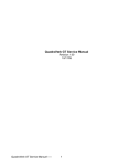
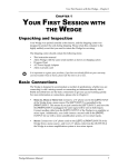
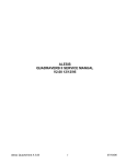


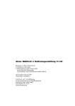

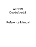


![Alesis F: [401] 658.3640 Specification Sheet](http://vs1.manualzilla.com/store/data/007079733_1-05dc2d0b66a4219f5954efc679680955-150x150.png)