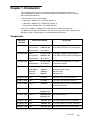
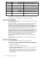
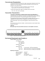
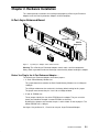
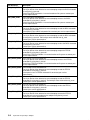
1
Bull DPX/20 ESCALA
8–Port & 128–Port Async Adapters
Installation and Configuration Guide
ORDER REFERENCE
86 A1 06GX 01
Bull DPX/20 ESCALA
8–Port & 128–Port Async Adapters
Installation and Configuration Guide
Hardware
September 1996
Bull Electronics Angers S.A.
CEDOC
Atelier de Reprographie
331 Avenue Patton
49 004 ANGERS CEDEX 01
FRANCE
ORDER REFERENCE
86 A1 06GX 01
The following copyright notice protects this book under the Copyright laws of the United States and other
countries which prohibit such actions as, but not limited to, copying, distributing, modifying, and making
derivative works.
Copyright
Bull S.A. 1992, 1996
Printed in France
Suggestions and criticisms concerning the form, content, and presentation of
this book are invited. A form is provided at the end of this book for this purpose.
Trademarks and Acknowledgements
We acknowledge the right of proprietors of trademarks mentioned in this book.
AIXR is a registered trademark of International Business Machines Corporation, and is being used under
licence.
UNIX is a registered trademark in the USA and other countries licensed exclusively through X/Open.
The information in this document is subject to change without notice. Groupe Bull will not be liable for errors
contained herein, or for incidental or consequential damages in connection with the use of this material.
About This Book
This manual describes the installation of the 8–Port Async Enhanced Adapters and the
128–Port Async Adapter in computers that use the MCA (Micro Channel Architecture) bus.
Who Should Use This Book
It is written for the technician who is to install the adapter.
Overview
The manual is organized as follows:
• Introduction
• Hardware Installation
• Software Installation and Configuration
• Connecting Peripherals
• Auto–tests, Diagnostics and Error Identifiers
Related Publications
AIX Asynchronous Communication Guide, 86 A2 26AQ.
Cabling Guide, 86 A1 87AQ.
AIX and Related Products Documentation Overview, 86 A2 71WE.
Preface
iii
Electronic Emission Notices
Federal Communications Commission (FCC) Statement
Radio Frequency Interference (RFI) (FCC 15.105)
This equipment has been tested and found to comply with the limits for Class B (8 port) and
Class A (128 port) digital devices pursuant to Part 15 of the FCC Rules. These limits are
designed to provide reasonable protection against harmful interference in a residential
environment. This equipment generates, uses, and can radiate radio frequency energy, and
if not installed and used in accordance with the instruction manual, may cause harmful
interference to radio communications. However, there is no guarantee that interference will
not occur in a particular installation. If this equipment does cause harmful interference to
radio or television reception, which can be determined by turning the equipment off and on,
the user is encouraged to try and correct the interference by one or more of the following
measures:
• Reorient or relocate the receiving antenna.
• Increase the separation between the equipment and the receiver.
• Connect the equipment into an outlet on a circuit different from that to which the receiver is
connected.
• Consult the dealer or an experienced radio/TV technician for help.
Labeling Requirements (FCC 15.19)
This device complies with Part 15 of FCC rules. Operation is subject to the following two
conditions: (1) this device may not cause harmful interference, and (2) this device must
accept any interference received, including interference that may cause undesired
operation.
Modifications (FCC 15.21)
Changes or modifications to this equipment not expressly approved by Bull may void the
user’s authority to operate this equipment.
Cables (FCC 15.27)
Shielded cables must be used to remain within the Class B limitations.
Industry Canada Compliance Statement
This digital apparatus does not exceed the Class B (8 port) and Class A (128 port) limits for
radio noise for digital apparatus set out in the interference–causing equipment standard
entitled: “Digital Apparatus”, ICES–003 of Industry Canada.
Cet appareil numérique respecte les limites de bruits radioélectriques applicables aux
appareils numériques de Classe B (8 port) and Class A (128 port) prescrites dans la norme
sur le matériel brouilleur : “Appareils numériques”, NMB–003 édictée par Industrie Canada.
iv
8-port and 128-port Async Adapters
Table of Contents
Chapter 1. Introduction . . . . . . . . . . . . . . . . . . . . . . . . . . . . . . . . . . . . . . . . . . . . . . . . . .
Components . . . . . . . . . . . . . . . . . . . . . . . . . . . . . . . . . . . . . . . . . . . . . . . . . . . . . . . . . .
About the Adapters . . . . . . . . . . . . . . . . . . . . . . . . . . . . . . . . . . . . . . . . . . . . . . . . . . . .
8–Port Async Enhanced Adapter Characteristics . . . . . . . . . . . . . . . . . . . . . . . . . .
Environment Requirements and Compliance . . . . . . . . . . . . . . . . . . . . . . . . . . . . . .
1-1
1-1
1-1
1-2
1-2
Chapter 2. Hardware Installation . . . . . . . . . . . . . . . . . . . . . . . . . . . . . . . . . . . . . . . . .
Before You Plug In the Adapter. . . . . . . . . . . . . . . . . . . . . . . . . . . . . . . . . . . . . . . . . .
Plugging in the Adapter . . . . . . . . . . . . . . . . . . . . . . . . . . . . . . . . . . . . . . . . . . . . . . . .
Configuration . . . . . . . . . . . . . . . . . . . . . . . . . . . . . . . . . . . . . . . . . . . . . . . . . . . . . . . . .
2-1
2-1
2-1
2-2
Chapter 3. Software Installation and Configuration . . . . . . . . . . . . . . . . . . . . . . . .
Software Delivery . . . . . . . . . . . . . . . . . . . . . . . . . . . . . . . . . . . . . . . . . . . . . . . . . . . . . .
Software Installation . . . . . . . . . . . . . . . . . . . . . . . . . . . . . . . . . . . . . . . . . . . . . . . . . . .
Adapter Configuration . . . . . . . . . . . . . . . . . . . . . . . . . . . . . . . . . . . . . . . . . . . . . . . . . .
TTY Configuration . . . . . . . . . . . . . . . . . . . . . . . . . . . . . . . . . . . . . . . . . . . . . . . . . . . . .
3-1
3-1
3-1
3-2
3-3
Chapter 4. Connecting Peripherals . . . . . . . . . . . . . . . . . . . . . . . . . . . . . . . . . . . . . . .
Connecting to a DTE Device . . . . . . . . . . . . . . . . . . . . . . . . . . . . . . . . . . . . . . . . . . . . . .
4-1
4-1
Chapter 5. Auto–tests, Diagnostics and Error Identifiers . . . . . . . . . . . . . . . . . .
Auto–tests . . . . . . . . . . . . . . . . . . . . . . . . . . . . . . . . . . . . . . . . . . . . . . . . . . . . . . . . . . . .
User Diagnostics . . . . . . . . . . . . . . . . . . . . . . . . . . . . . . . . . . . . . . . . . . . . . . . . . . . . . .
Traces . . . . . . . . . . . . . . . . . . . . . . . . . . . . . . . . . . . . . . . . . . . . . . . . . . . . . . . . . . . . . . .
Error Identifiers for the Error Log . . . . . . . . . . . . . . . . . . . . . . . . . . . . . . . . . . . . . . . .
5-1
5-1
5-1
5-2
5-3
Preface
v
vi
8-port and 128-port Async Adapters
Chapter 1. Introduction
This Installation Guide covers the installation and configuration of the 8–Port Async
Enhanced Adapters and the 128–Port Async Adapters for an MCA bus (“MCA” stands for
Micro Channel Architecture).
There are three versions of the adapter:
• 8 port Async. Adapter EIA – 232 (MCA) Type B3–5
• 8 port Async. Adapter EIA – 422A (MCA) Type B3–6
• 128 port Async. Adapter EIA – 232 (MCA) Type B3–7
Each 8–Port adapter is composed of a circuit board and a DB25 connector box.
In addition to the board itself (hardware), you must also install device driver software for the
operating system, so that programs can communicate with the board.
Components
Marketing
Identification Number
Designation
Identifier
DCCG067–0000 Board
76729369–001
8–Port Async. Adapter EIA–232 (MCA)
Connector Box
50000340–001
8–Port DB25 DTE EIA–232 Connector Box
Documentation
86 A1 06GX
DCCG068–0000 Board
76729371–001
8–Port Async. Adapter EIA–422A (MCA)
Connector Box
50000422–001
8–Port DB25 DTE EIA–422A Connector Box
Documentation
86 A1 06GX
DCCG018–0000 Board
76729537–001
128–Port Async. Adapter EIA–232 (MCA)
86 A1 06GX
2 terminators included
76729413 -001
C/CON–16 Subsystem
Power Supply
10000895
International Power Supply
Terminator
60000388
Terminator DB15
Wrap plug
60000401
Wrap plug RJ45
CBLG032–1700
Cable
62110180
4.6m Cable Local EIA–422 (15M/15F)
CBLG033–1000
Cable
62110009
0.2m Cable Local EIA–422 (15M/15F)
CKTG016–0000
Cable x 4
61020024
0.2m Cable local EIA–232 (RJ45M/25M) for
Documentation
DCCG019–0000 Concentrator
128–Port Concentrator
CKTG025–1800
Cable x 2
900090001–001 7.5m Cable BCS/PCS
90010001–001
CKTG026–1800
Cable x 2
900090001–001 7.5m Cable BCS/PCS
90010001–001
CBLG039–1700
Cable
90005001–001
4.6m Cable modem EIA–232 (15M/25M)
CBLG040–1700
Cable
90006001–001
4.6m Cable modem EIA–422A (15M/37M)
CBLG041–1700
Cable
90007001–001
4.6m Cable modem EIA–232 (15F/25M)
Introduction
1-1
CBLG042–1700
Cable
90008001–001
4.6m Cable modem EIA–422A (15F/37M)
CBLG104–1600
Cable
90232001–001
3.5m Cable Local EIA–232 (25F/25M)
CBLG104–2000
Cable
90232002–001
15m Cable Local EIA–232 (25F/25M)
CBLG105–1800
Cable
90233002–001
7.5m Cable Local EIA–232 (25F/25F)
CBLG106–2000
Cable
90234001–001
15m Cable Local EIA–232 (25F/25M)
CBLG107–1200
Cable
90235001–001
1.5m Cable Local EIA–422A (25F/15M)
CBLG108–2000
Cable
90236001–001
15m Cable BCS1 with Sub-D (25F/15M)
CBLG109–2000
Cable
90237001–001
15m Cable BCS2 with Modular Jack
(25F/RJ45M)
8–port Software driver and diagnostics are provided on the Bull–Enhancements CD–ROM.
128–port Software driver and diagnostics are provided on the AIX CD–ROM.
About the 8–Port Adapters
The 8 port Async Enhanced Adapters are multi–channel intelligent serial communications
boards for MCA computers.
The heart of the Adapters is an 80C186 microprocessor and 256K bytes of dual ported
RAM, which relieves your computer of the burden of managing the serial ports. The
computer can transfer large blocks of data directly to the memory on the adapter, then move
on to other tasks while the adapter sends the data out the serial port one character at a
time. Similarly, the adapter receives input data and stores it in buffers in its dual ported
RAM, so the computer only needs to check periodically to see if data is available.
The dual ported RAM is memory which is accessible for read and write operations by both
the adapter and the computer. To the computer, the dual ported RAM looks exactly like its
own memory, and can be accessed by the same high speed memory referencing
commands it uses for its internal memory. This means that a block of data that may take a
number of seconds for the adapter to receive or transmit to the outside world can be
transferred between the adapter and the computer in mere microseconds.
The dual ported RAM is “mapped” into an unused area in the host computer’s memory
address space.
The 8–Port Async Enhanced Adapters provide either eight EIA–232 or eight EIA–422A
communication ports.
About the 128–Port Adapters
The 128–Port Async Adapters provide 128 EIA–232 communication ports.
The 128–Port Async Adapter is an intelligent dual–channel EIA–422 synchronous board for
the AIX system. The 128–Port Async Adapter features the following main components:
• 10 MHz 80C186 microprocessor.
• 10 MHz 82C37 direct memory access (DMA) controller.
• 512K of tri–ported dynamic RAM (tri–ported between the host CPU, the local 80C186
microprocessor, and the DMA controller).
• Two high–speed EIA–422 synchronous lines (or channels) used to communicate with
128–port RAN (Remote Asynchronous Nodes) at data rates of up to 1.2 Mbps. The
synchronous lines are also capable of communicating with EIA–422 and EIA–232
synchonous modems.
1-2
8-port and 128-port Async Adapters
Connector–box Characteristics
The 8–port connector–box picks up all the signals concerning the eight ports on the 78–pin
connector of the 8–Port Async Enhanced board and dispatches them on eight 25–pin
connectors, one for each channel.
The EIA–232 connector–box supplies the following signals for each port:
TxD, RxD, RTS, CTS, DSR, DTR, DCD, RI and Ground.
The EIA–422A connector–box supplies the following signals for each port:
TxD+, TxD–, RxD+, RxD– and Ground.
Concentrator Characteristics
The C/CON-16 concentrator is a complete subsystem with its own 16MHz 80C186
microprocessor, 128K of RAM and 16K of EPROM, 16C550-compatible UARTs for the
sixteen RJ45 EIA-232 asynchronous serial ports, and a high-speed synchronous EIA-422A
port for communication with the 128–port host adapter and other concentrators.
The concentrator receives packets of data from the host adapter at data rates of up to 1.2
megabaud, then distributes the data, as appropriate, to the sixteen EIA-232 ports.
Up to 4 concentrators may be daisy chained together on each of the two lines of the
adapter.
By using high-speed synchronous modems, remote concentrators may be located virtually
anywhere in the world.
CAUTION:
Back panel logo warns that the RJ45 connectors are not telephone connectors.
0
1
2
3
4
5
6
7
8
9
10
11
12
13
14
15
Figure 1. 16 port Concentrator (RAN) Back Panel
Environment Requirements and Compliance
Electrical power source loading
8–port EIA–232:
+5V : 1.8 A max
+12V : 80mA max
–12V : 80mA max
8–port EIA–422A:
+5V : 1.9 A max
128-port EIA–232:
+5V +/–5%
+12V +/–5%
–12V +/–5%
: 2 A for the host + 0.75 A per concentrator
: 40 mA max for the host + 0.18 A per concentrator
: 40 mA max for the host + 0.05 A per concentrator
Operating environment
Ambient temperature
Relative humidity
Air movement
Altitude
: 10 to 55 _C
: 5 to 90%
: 30 CFM forced
: 0 to 3660 m (12,000 feet)
Introduction
1-3
1-4
8-port and 128-port Async Adapters
Chapter 2. Hardware Installation
This section provides instructions for installing and configuring 8–Port Async Enhanced
Adapters and 128–Port Asynchonous Adapters in MCA computers.
8–Port Async Enhanced Board
Endplate
DB–78
Connector
J5
J6
.........
........
........
........
........
........
........
.
J1
Fork
Figure 1. 8-port Async. Adapter and its Connector box
Warning: The 8-Port Async Enhanced Adapters contain static–sensitive components.
Always touch a grounded surface to discharge static electricity before handling the adapter.
Before You Plug In the 8–Port Enhanced Adapter. . .
The 8-Port Async Enhanced Adapters have three jumpers:
• J1: Dual–Ported Memory Window size
This jumper determines whether the Dual–Ported Memory Window size is 32Kbyte or
128Kbyte.
The 32Kbyte window must be used and is the factory default setting for this jumper.
The jumper must connect the pins 2 and 3 for a 32Kbyte window.
• J5 and J6: EPROM size
These jumpers identify the size of the EPROMs on the adapter. They are set at the
factory and should be changed if custom EPROMs are installed.
By default, the jumpers must connect the pins 1 and 2 of both J5 and J6 jumpers. The
default EPROM size is 16Kbyte.
See figure 1 the position of J1, J5 and J6 on a 8-port Async Enhanced Adapter.
Hardware Installation
2-1
Plugging in the Adapter
Now you are ready to install the 8-Port Async Enhanced Adapter in your computer.
128–Port Asynchronous Board
........
......
.
line 1
........
......
.
line 2
Figure 1. 128-port Async Adapter
Warning: The 128-Port Async Adapters contain static–sensitive components. Always touch
a grounded surface to discharge static electricity before handling the adapter.
8–Port and 128–Port Adapter Installation
1. Turn off your computer’s power and remove the cover (refer to your computer’s manual
for instructions on cover removal and option board installation and cautions)
2. Locate an available Micro Channel slot in your computer and remove the external slot
plate (you will need to loosen the thumbscrew to do this).
3. Plug the Adapter into a MCA slot, making sure that the ”fork” is in the position under the
endplate thumbscrew. Tighten the thumbscrew.
4. for the 8–Port Adapter, install the connector box on the adapter by mating the female
78-pin connector on the assembly to the male 78-pin plug on the end of the Adapter.
for the 128–Port Adapter, install the interface cable assembly by mating the female DB15
connector on the assembly to the male DB15 plug on the end of the Adapter.
Be sure that the plug is completely installed–it may be a snug fit.
5. Screw the connector into the board’s endplate. Do not over-tighten the screws. If the
screws don’t go in several turns, or if they don’t reach the nuts in the endplate, the 78-pin
or DB15 connectors are probably not completely mated.
6. Replace your computer’s cover.
7. Reconnect the power cable to the system; then turn on the power.
2-2
8-port and 128-port Async Adapters
62110009
1n
Terminator plug
installed on
”Remote” port
2n
3n
4n
43G0935
Line 1
62110180
62110009
Terminator plug
installed on
”Remote” port
Line 2
Adapter
1n
2n
3n
4n
Figure 2. Eight C/CON–16 connected locally
62110009
Terminator plug
installed on
”Remote” port
1n
3n
2n
Modems
Line 1
62110180
90005001-001 for RS232 modem
90006001-001 for RS422 modem
90007001-001 for RS232 modem
90008001-001 for RS422 modem
Line 2
62110009
Adapter
1n
Terminator plug
installed on
”Remote” port
2n
Modems
Figure 3. Local and remote C/CON–16
Warning: Each line must be terminated by a terminator.
Hardware Installation
2-3
Installing the 128-Port Concentrator (RAN)
The adapter identifies Remote Asynchronous Nodes (RANs) by their node numbers. Each
RAN in a daisy chain must have a unique node number (1n-4n), which must be set during
installation. The node numbers must be assigned in ascending order with the lowest
number assigned to the RAN closest to the adapter. You can skip node numbers (to
facilitate insertion of additional RANs at a later date), as long as the ascending sequence is
maintained.
Setting the RAN Node Number
1. Turn the RAN on and wait for the power-on self-test (POST) to complete.
2. When P1 is displayed on the front panel seven-segment LED display, press the Left
Arrow button once. The current node number will be displayed, for example, 1n for
node 1.
3. Press the Right Arrow button to advance the node number through the eight possible
settings (1n-8n). Only 1n-4n are supported, 5n-8n can be displayed but are not
supported node numbers.
4. When the desired node number is displayed, press the Left Arrow button again to select
the number. The display should now read Pn (indicating a pass condition). If there was
an error, the display will read En.
In the case of duplicate node numbers, the RAN farthest from the host adapter will
display En, instead of AC, when the system is started.
CCITT
103 104 105 106 107 109 108 125
TD
RD RTS CTS DSR CD DTR
RI OFC IFC
100%
0%
LED Indicators
7-Segment Display
Push
buttons
Figure 4. 16 port Concentrator (RAN) Front Panel
RAN Front Panel and Display Modes
The LED indicators can be used to reflect the activity of each of the EIA-232 lines and flow
control status for a given line. They can also be set to act as a bar graph to show CPU
utilization and the activity level of the EIA-422 synchronous line.
The RAN front panel display has several different display modes as indicated by the
two-digit, seven-segment display. Pushing the Right or Left arrow push buttons will cycle
the display sequentially through the modes.
2-4
8-port and 128-port Async Adapters
The following table describes the RAN display modes.
RAN Display Modes
Mode
Mode Name
Description
P1
POST
Complete
P1 appears on the seven-segment display. Power-on self-test is complete, relays are open waiting for connection.
P2
Ping Packet
Receive
P2 appears on the seven-segment display. Indicates that the operating system successfully transmitted a ping packet to RAN. The ping
packet contains configuration information used by the RAN (for example baud rate, type of interface.)
P3
Transmit
Configuration
Packet
P3 is not displayed on the seven-segment display. The RAN transmits
a packet that contains information about the RAN’s physical characteristics. The operating system uses this information to determine
which download image to send to the RAN. The RAN does not receive
conformation that the operating system has received the packet.
P4
Image Receive
P4 appears on the seven-segment display. Download image is being
received from the host. The RAN will normally stay at P4 for a length
of time, depending on the synchronous baud rate being used.
AC
Activity
AC appears on the seven-segment display. The 10 LEDs turn on sequentially from left to right. The speed of this “chase light” display increases with the overall activity level of the RAN.
00–15
Line Monitor
00-15 appears on the seven-segment display. Modes 00 through 15
correspond to channels 0 through 15. Press the right or left push buttons until the desired channel number appears in the seven-segment
display. The LEDs act as line monitor for the selected channel. The
first eight LED indicators show the activity of each of the eight EIA-232
signals (TD, RD, RTS, CTS, DSR, DCD, DTR and RI). The last two
LED indicators show when output flow control (OFC) and input flow
control (IFC) are active.
En
Error Node
En appears on the seven-segment display. Indicates that a valid ping
packet was received but the node number in EEPROM is incorrect.
PC
Packet Count
PC appears on the seven-segment display. The 10 LEDs show a
binary representation of the total number of packets transmitted or
received. Pressing both push buttons simultaneously resets the count
to 0.
EC
Error Count
EC appears on the seven-segment display. The 10 LEDs show a
binary representation of the total number of errors counted in the data.
Pressing both pushbuttons simultaneously resets the count to 0.
PU
Processor
Utilization
PU appears on the seven-segment display. The 10 LEDs become a
bar graph indicating the percentage (0–100%) of the time the RAN
microprocessor is being used.
LU
Line Utilization
LU appears on the seven-segment display. The 10 LEDs become a
bar graph indicating the percentage (0–100%) of the time that the
synchronous communications line is being used.
1n, 2n,...,8n
Node Number
The seven-segment display shows the node number of the RAN.
Note: * Only node numbers 1n through 4n are valid. Node numbers 5n through 8n are not
supported.
Hardware Installation
2-5
Configuration
No action is required to configure the adapters. The Memory Start Address and the I/O Port
Address are selected by the bus resolver.
The 8–Port possible values are:
• Memory Start Address
E90000h, EA000h, EB0000h or EC0000h.
The default value is E90000h.
• I/O Port Address
F1F0h, F2F0h, F4F0h or F8F0h.
The default value is F1F0h.
The 128–Port possible values are:
• Memory Start Address
040000h to F80000h, in steps of 040000h.
The default value is 040000h.
• I/O Port Address
108h, 118h, 128h, 208h, 228h, 308h, 328h.
The default value is 108h.
2-6
8-port and 128-port Async Adapters
Chapter 3. Software Installation and Configuration
Software Delivery
8–Port Async Enhanced Adapter
The installation is done with the DPX/20 ESCALA Bull Enhancement Installation Bundle.
It contains the following LPPs.
1. bullasync.base, which contains the common part for all the asynchronous adapters.
It contains one OPP:
bullasync.base.rte
microcodes and common utilities
2. bullasync.mca, which is necessary to support MCA asynchronous adapters. It
contains two OPPs:
bullasync.mca.diag
diagnostics tests
bullasync.mca.rte
driver, methods and specific utilities
3. devices.mca.7f99, which allows the automatic installation of the 8–Port Async
Enhanced Adapter EIA–232 software. It contains one OPP:
devices.mca.7f99.rte pre–requisite on bullasync.mca
4. devices.mca.7f9a, which allows the automatic installation of the 8–Port Async
Enhanced Adapter EIA–422A software. It contains one OPP:
devices.mca.7f9a.rte pre–requisite on bullasync.mca
128–Port Async Adapter
The software is included in the AIX delivery. It contains the following LPPs.
1. devices.mca.ffe1.ucode
microcodes
2. devices.mca.ffe1.rte
software
3. devices.mca.ffe1.diag
diagnostics tests
Software Installation
The software is normally pre-installed. You can verify the software installation with the lslpp
command.
If for some reason it must be reinstalled, proceed as follows:
1. Turn the computer on.
2. Log in as root.
3. Insert the media containing the device driver software into the appropriate media device,
for example, CD–ROM drive.
4. Enter:
smit cfgmgr
and press Enter.
The Install/Configure Devices Added After IPL screen is displayed. The
”INPUT device/directory for software” option is highlighted. The cursor is positioned on
the entry field where you will identify the input device you are using.
5. Press F4 to display a list of input devices you can select.
6. Select the device by moving the cursor to the appropriate media type and pressing Enter.
Software Installation
3-1
The device or directory you selected is now displayed in the ”INPUT device/directory for
software” option on the Install/Configure Devices Added After IPL screen.
7. Press Enter to execute the software installation command.
The COMMAND STATUS screen is displayed. The status will change from Running to
OK when the software installation is complete.
Note: If an error message is displayed on the COMMAND STATUS screen, verify that the
adapter card is seated properly. If the card is secure, refer to the documentation that
came with your computer for information on running hardware diagnostics.
8. Remove the installation media from the drive.
9. Press F10 to exit SMIT.
10.At the prompt, enter:
shutdown –Fr
and press Enter.
This will shut down and reboot your system. This is a necessary final step in the installation
process. AIX will configure your adapter card automatically when the system reboots. No
additional procedures are required.
Adapter Configuration
After having loaded the software you must re–configure the operating system to recognize
the Asynchonous Adapters.
To re–configure the system, you can use:
• the system reboot or
• the cfgmgr command or
• the smit interface:
#smit dev and choose the sub–menu ”Configure Devices Added after IPL”
You can check the successful installation with the lsdev command, which lists the adapters
installed on the system.
For instance:
#lsdev –C
sa0
sa1
sa2
sa3
cxma0
sa4
Available 00–00–S1
Available 00–00–S2
Available 00–01
Available 00–02
Available 00–03
Available 00–03–xy
Note: x: line number (1 or 2)
y: RAN number (1 to 4)
3-2
8-port and 128-port Async Adapters
Standard I/O Serial Port 1
Standard I/O Serial Port 2
8–Port Async Enhanced Adapter EIA–232
8–Port Async Enhanced Adapter EIA–422A
128–Port Asynchronous Adapter
16–Port RAN EIA–232 for 128–Port Adapter
TTY Configuration
This procedure allows you to define and configure a tty device connected to an 8-Port
Async Enhanced adapter.
Procedure
1. Enter the SMIT fast path:
smit tty
Note: Depending on your environment, you access SMIT in ASCII mode or AIXwindows
mode. The following steps apply to both interfaces.
2. Select Add a TTY.
For an 8-Port Async Enhanced or a 128-Port Async adapter EIA–232:
1. Select tty rs232 Asynchronous Terminal.
2. Make a selection from the available 8-Port Async Enhanced adapter EIA–232 displayed
on the screen. If no adapters are displayed or if they are in a defined state, check the
configuration, cabling and setup again.
The SMIT panel for this selection resembles the following figure.
TTY
Move cursor to desired item and press Enter.
Parent Adapter
Move cursor to desired item and press Enter.
sa0
Available 00-00-S1
sa1
Available 00-00-S2
sa2
Available 00-02
sa3
Available 00-02–11
F1=Help
F2=Refresh
F1=Help
F5=Undo
F6=Command
F8=Image
F9=Shell
F10=Exit
Standard I/O Serial Port 1
Standard I/O Serial Port 2
8-Port Async Enhanced Adapter EIA-232
16–Port RAN EIA–232 for 128–Port Adapter
F3=Cancel
F4=List
F3=Cancel
F2=Refresh
F7=Edit
F8=Image
Enter=Do
F10=Exit
Enter=Do
For an 8-Port Async Enhanced adapter EIA–422A:
1. Select tty rs422 Asynchronous Terminal.
2. Make a selection from the available 8-Port Async Enhanced adapter EIA 422A displayed
on the screen. If no adapters are displayed or if they are in a defined state, check the
configuration, cabling and setup again.
The SMIT panel for this selection resembles the following figure.
TTY
Move cursor to desired item and press Enter.
Parent Adapter
Move cursor to desired item and press Enter.
sa0
sa1
sa3
Available
Available
Available
F1=Help
F1=Help
F5=Undo
F8=Image
F9=Shell
00-00-S1
00-00-S2
00-03
F2=Refresh
F6=Command
F10=Exit
Standard I/O Serial Port 1
Standard I/O Serial Port 2
8-Port Async Enhanced Adapter EIA-422A
F3=Cancel
F2=Refresh
F7=Edit
F10=Exit
Enter=Do
F4=List
F3=Cancel
F8=Image
Enter=Do
Software Installation
3-3
When the appropriate adapter is selected, a SMIT panel resembling the following figure will
be displayed depending on the AIX release level:
Add a TTY (Version 4.1)
Type or select values in entry fields.
Press Enter AFTER making all the desired changes.
[Entry Fields]
TTY type
tty
TTY interface
EIA232
Description
Asynchronous Terminal
Parent Adapter
sa3
*PORT number
[]
Enable LOGIN
disable
BAUD rate
[9600]
PARITY
[none]
BITS per character
[8]
Number of STOP BITS
[1]
TIME before advancing to next port setting
[0]
TERMINAL type
[dumb]
FLOW CONTROL to be used
[xon]
OPEN DISCIPLINE to be used
[dtropen]
STTY attributes for RUN time
[hupcl,cread,brkinit,icr.
STTY attributes for LOGIN
[hupcl,cread,echoe,cs8,.
LOGGER name
[]
STATUS of device at BOOT time
[available]
STREAMS modules to be pushed at OPEN time
[ldterm,tioc]
Transparent Print ON String
[\033[5i]
Transparent Print OFF String
[\033[4i]
Transparent Print Maximum Characters per Second [100]
Transparent Print Maximum Characters Packet Size[50]
Transparent Print Buffer Size
[100]
Ignore Carrier Detect
disable
Receive Event Delay Time
[100]
2200 Flow Control
disable
2200 Print Control
disable
INPUT map file
[none]
OUTPUT map file
[none]
CODESET map file
[sbcs]
POSIX special control characters:
INTERRUPT character
[^c]
QUIT character
[^\]
ERASE character
[^h]
KILL character
[^u]
END OF FILE character
[^d]
[More]
F1=Help
F5=Undo
F9=Shell
3-4
F2=Refresh
F6=Command
F10=Exit
8-port and 128-port Async Adapters
F3=Cancel
F7=Edit
Enter=Do
F4=List
F8=Image
+
+
+
+
+
+#
+
+
+
+
+
+#
+#
+#
+
+#
+
+
+
+
+
SMIT Field Definitions for TTY port
The following is a summary of the tty attributes and values shown on the SMIT Add a TTY
screen.
TTY type
Identifies the predefined tty device type. The value of this field cannot be
changed.
TTY interface Identifies the predefined tty device subclass. The value of this field cannot
be changed.
Description
Provides a short text description of the tty device. The value of this field
cannot be changed. The short text is used to assist device locations.
Parent adapter Identifies the logical name of the adapter device to which the tty is to be
attached. The value of this field cannot be changed.
PORT number Indicates the port on an adapter card or asynchronous distribution box to
which the tty device is connected. The value must be in the range:
• 0 through 7 for an 8-port adapter board.
• 0 through 15 for a 128-port adapter board.
Enable LOGIN Indicates whether a getty process is to be run on the port to allow user
login. Possible values are:
disable
enable
share
BAUD rate
PARITY
No getty process is run on the port.
A getty process is run on the port.
A getty process is run on the port, but the getty process still
allows programs dialing out on the port to share it by
waiting for an open of the port to complete before
attempting to get the tty lock. If an active process already
owns the lock, the getty process lets that process own the
tty port until the lock goes away.
delay
A getty process (for example, share) is run on port in
bi-directional mode, but no herald is displayed until the
getty process receives a keystroke from the user.
Specifies the speed that data is transmitted to and from this port. Possible
settings are values such as 300, 600, 1200, 2400, 4800, 9600, 19200, or
38400. The actual values that can be used vary among the possible
devices that can be attached as tty devices.
Provides a means for detecting errors in the data transmitted to and from
the device. The five possible parity settings are odd, even, none, mark, and
space.
BITS per character
Indicates the number of bits per character to be transmitted to and from the
device. The possible values are 5, 6, 7, and 8.
Number of STOP BITS
Indicates the number of stop bits transmitted to and from the device. The
possible choices are 1 and 2.
TIME before advancing to next port setting
If a user name is not specified before the given number of seconds, the
getty process advances to the next port setting or exits if all settings are
exhausted. Note that the getty process advances to the next setting before
the specified time has elapsed if a framing error occurs as a result of a
BREAK on the line or a speed mismatch.
Software Installation
3-5
TERMINAL type
Identifies the default type of terminal attached to a port. A variety of
applications and system functions are tailored to specific terminal types.
Since terminal devices are not typically asked to identify themselves, this
attribute is used to set the TERM environment variable.
FLOW CONTROL to be used
Describes how a serial device controls the amount of data being
transmitted to itself. The three types of flow control used with ttys are
XON/XOFF, RTS/CTS, and DTR/DSR.
XON/XOFF involves the sending of data transmission control characters
along the data stream. It is referred to as software flow control.
RTS/CTS, sometimes called pacing or hardware handshaking, uses
positive and negative voltages along dedicated pins or wires in the device
cabling. The term hardware handshaking comes from the use of cabling
and voltages as a method of data transmission control.
DTR/DSR, another form of hardware flow control, is normally generated by
the devices, such as printers to indicate that they are ready to communicate
with the system. This signal is used in conjunction with data set ready
(DSR) generated by the system to control data flow.
The FLOW CONTROL selection must match the device control setting in
order to prevent data loss. Possible values are: xon, rts, and none. The
default is xon.
OPEN DISCIPLINE to be used
Specifies how to establish the connection. Possible values are: dtropen and
wtopen. The use of dtropen means the system waits until the EIA signal
DTR (Data Terminal Ready) is sent by the remote device before completing
the open (port) request from the application.
STTY attributes for RUN time
Consists of a list of attributes used to configure the port after the login
procedure is successfully completed. The list consists of command
parameters.
STTY attributes for LOGIN
Consists of a list of attributes that are valid while you are attempting to log
in to the system. This is normally a subset of the modes available at run
time since few of the line discipline’s processing features are required at the
time of login. This list consists of command parameters.
Optional LOGGER name
Names an optional logger program to be used instead of the default logger
program. This field must be left blank for the default logger program to be
used.
STATUS of the device at BOOT time
Indicates the state to which the device is to be configured when the system
is started. It can have a value of “defined,” indicating that the device will be
left in the defined state and not available for use, or a value of “available,”
indicating that the device will be configured and available for use.
STREAMS modules to be pushed at OPEN time
Specifies a comma-separated list of pushable STREAMS modules. The tty
subsystem implementation uses the STREAMS framework. These modules
are pushed at open time in the order they are specified. The default value
for terminal session is: ldterm, tioc.
3-6
8-port and 128-port Async Adapters
Transparent Print ON String
Specifies the control codes (or data string) necessary to instruct the
attached terminal to send all data received after the string to the printer port
and not to the terminal’s display. The transparent print on string is an octal
number preceded by a backslash (\\) and is specific to the type of terminal
in use. Please consult your terminal reference guide for the transparent
print on control sequence. For example, the print–on string for an IBM 3151
terminal is \\020\\022.
Transparent Print OFF String
Specifies the octal control codes (or data string) necessary to instruct the
attached terminal to exit the transparent printing operation. This string is an
octal number preceded by a backslash (\\), and is specific to the type of
terminal in use. Please consult your terminal reference guide for the
transparent print off control sequence. For example, the print–off string for
an IBM 3151 terminal is \\020\\024.
Transparent Print Maximum Characters per Second
Specifies the maximum characters per second (cps) rate at which to send
characters to the transparent print device. A number just below the average
print speed is recommended. If the estimate is too low, printer speed is
reduced. If the estimate is too high, the printer performs flow control, which
can impair terminal performance. See the printer manual for the valid entry
range. The default rate is 100 cps.
Transparent Print Maximum Character Packet Size
Specifies the maximum number of characters to send in one transparent
print buffer. Small packets can increase system overhead; large packets
can delay display updates when the transparent printer is in use. Consult
the printer manual for the valid entry range. The default packet size is 50
characters.
Transparent Print Buffer Size
Specifies the size of the transparent printer’s input buffer. After a period of
inactivity, the device driver bursts the specified number of characters to the
transparent printer before slowing to the specified maximum
characters–per–second transfer rate. This insulates the printer from the line
transfer rate so that it can immediately begin printing at full capacity.
Consult the printer documentation to determine the size of the printer’s
input buffer. The default buffer size is 100 characters.
Ignore Carrier Detect
Ignores the carrier detect signal for this tty port. Typically, carrier detect
must be high in order to open a port and it must remain high for as long as
the port is open. Possible values are enable (ignore carrier detect) and
disable (do not ignore carrier detect). The default value is disable.
Receive Event Delay Time
Tunes the frequency that packets are sent to the host adapter from the
remote async node (RAN) for this tty. Possible values are from 100 to 400.
Selecting a larger value (250 and above) results in more characters being
sent in a given time period and yields improved performance in cases of
continuous raw data input. Smaller values, which result in fewer characters
being sent, increased character response time, and increased processor
utilization, should be reserved for normal tty activity such as typing and
uucp. The default value is 100.
Software Installation
3-7
2200 Flow Control
Determines if Wang Series 2200 terminal flow control is to be used. Wang
2200 series terminals support an attached printer and use four flow–control
characters: Terminal XON (0xF8) Terminal XOFF (0xFA) Printer XON
(0xF9) Printer XOFF (0xFB) Possible values are enable (to use 2200 flow
control) and disable (to use regular flow control). The default value is
disable.
2200 Print Control
This attribute is valid only if 2200 flow control is set to enable. It determines
how the 2200 flow control characters are interpreted. If 2200 print control is
set to enable, the system runs independent flow controls for terminal and
transparent print devices. Otherwise, terminal and printer flow control are
logically tied together so that if either a terminal or printer XOFF character
is received, both terminal and printer output is paused until the matching
XON character is received. The default value is disable.
INPUT map file
Identifies the name of the terminal input map that describes how to convert
extended characters in the data stream to the characters supported by
asynchronous terminals. The default value is none. Other possible values
are vt220 and ibm3161–C. Still other values are possible if additional input
map files have been placed in the /usr/lib/nls/termmap directory. See the
setmaps command for additional details.
OUTPUT map file
Identifies the name of the terminal output map that describes how to
convert extended characters in the data stream to the ASCII characters
supported by asynchronous terminals. The default value is none. Other
possible values are vt220 and ibm3161–C. Still other values are possible if
additional output map files have been placed in the /usr/lib/nls/termmap
directory. See the setmaps command for additional details.
CODESET map file
Identifies the name of the code set map file that describes the code set to
be used (single or multibyte codeset, EUC or non–EUC codeset, possible
converter modules, etc.).
The code set associated with most languages is a single byte code set
(sbcs). These code sets require that every possible displayable element
occupy one display position on a terminal. However, some Asian
languages, such as Japanese, Korean and Taiwanese, require multibyte
code sets, where one displayable element requires multiple byte
representation and occupies multiple display positions on a screen.
The default code set map file is sbcs. If your system requires a multibyte
code set, select the appropriate alternative. Alternatives are possible only if
other code set map files have been placed in the /usr/lib/nls/csmap
directory. See the setmaps command for more details.
3-8
8-port and 128-port Async Adapters
Chapter 4. Connecting Peripherals
Connecting to a DTE Device
A DTE device is a terminal, serial printer, another computer’s serial port, etc. To connect the
Asynchronous Serial Communications Adapter (which are also DTE devices) to another
DTE device, you need one of the following cables.
Local Connection:
EIA–232
CBLG104–1600
CBLG104–2000
CBLG105–1800
25F/25M Cable
25F/25M Cable
25F/25F Cable
3,5m
15m
7,5m
25F/15M Cable
25F/15M Cable
25F/RJ45M Cable
1,5m
15m
15m
EIA–422A
CBLG107–1200
CBLG108–2000
CBLG109–2000
Remote Connection Via a Modem:
CBLG106–2000
25F/25M Cable
15m
See ”Multiport Adapters” in the Bull DPX/20 Cabling Guide, for more information about
these cables.
Connecting Peripherals
4-1
4-2
8-port and 128-port Async Adapters
Chapter 5. Auto–tests, Diagnostics and Error
Identifiers
Auto–tests
The auto–tests only run when AIX is launched at the boot time. They permit the adapter to
be tested with internal loopback mode.
If the auto–tests fail, the adapter status is set to ”Defined” and a report is generated in the
system Errorlog which can be displayed later with the errpt command.
errpt –a –N ”sa<n>”
If an error is detected, perform the following:
• Power off the machine,
• Check the installation,
• Reboot the machine.
or
• Run the user diagnostics menus, to know more about the defect,
• Restart the adapter (mkdev –l ”sa<n>”).
If the error persists, call your Bull Representative.
User Diagnostics
The user diagnostic program must be used to check or identify a failure of the board or the
connector box.
The user diagnostics allow to check the dual–ported memory and to run an internal
loopback on all the ports.
Prerequisites
• The bullasync.mca.diag (8–Port), or the devices.mca.ffe1.diag (128–Port)
software must be installed.
• The ”Hardware Diagnostics” software (bos.diag.rte) must be installed,
• The tty (if any) associated to the adapter must be in a ”defined” state.
User Diagnostics under smit
Type smit and select the following:
Problem Determination
(Fastpath = smit [–C] diag)
Hardware Diagnostics
Current Shell Diagnostics
Diagnostic Routines
System Verification
Choose the board to test into the DIAGNOSTIC SELECTION menu.
The adapter is OK if the COMMAND STATUS report is OK, else a clear diagnostic is
displayed showing the appropriate action to be taken.
Auto–test and user diagnostics
5-1
Traces
The trace hook id for the Async Enhanced Adapters is 408.
To start the traces, you can use:
• the trace command:
#trace –j 408 –a
• the smit interface:
#smit trace and choose the sub–menu ”Start Trace” then select the ADDITIONAL event
IDs to trace
408 (STTY CXMA / MCXI)
To stop the traces, you can use:
• the trcstop command:
#trcstop
• the smit interface:
#smit trace and choose the sub–menu ”Stop Trace”
To generate a trace report, you can use:
• the trcrpt command
#trcrpt
• the smit interface
#smit trace and choose the sub–menu ”Generate a Trace Report” screens allow you to
customize your report.
5-2
8-port and 128-port Async Adapters
Error Identifiers for the Error Log
Error Identifiers
Description
MCXI_CFG_PORT
Bad Adapter I/O Port Address.
The Async device driver received a bad adapter I/O port address from the
configuration method.
The ODM database may be corrupted.
MCXI_CFG_RS
Adapter Reset Failed.
The Async adapter did not respond to a hardware reset.
Run the diagnostics against the failing device or contact your service
representative.
MCXI_CFG_MTST
Adapter Memory Test Failed.
The Async device driver detected an error during a memory test of the Async
adapter’s dual–ported memory.
Run the diagnostics against the failing device or contact your service
representative.
MCXI_CFG_BIOS
Adapter BIOS Initialization Failed.
An error occurred executing the Async adapter BIOS microcode.
Run the diagnostics against the failing device or contact your service
representative.
MCXI_CFG_FEPOS
Adapter FEPOS Execution Failed.
An error occurred executing the Async adapter FEPOS microcode.
Run the diagnostics against the failing device or contact your service
representative.
MCXI_CFG_MPORT
Bad or Missing Port on Adapter.
The Async device driver detected an error attempting to access a non–existing
port on an adapter.
Run the diagnostics against the failing device or contact your service
representative.
MCXI_CFG_TALLOC talloc failed.
The Async device driver detected an error attempting to allocate a trb timer
structure.
Contact your service representative.
MCXI_IO_ATT
I/O Segment Attach Failed.
The Async device driver detected an error attempting to attach to I/O memory.
Run the diagnostics against the failing device or contact your service
representative.
MCXI_MEM_ATT
Memory Segment Attach Failed.
The Async device driver detected an error attempting to attach to bus memory.
Run the diagnostics against the failing device or contact your service
representative.
MCXI_ADP_FAIL
Async Adapter Failed.
The Async device driver detected an unrecoverable error communicating with the
adapter.
Run the diagnostics against the failing device or contact your service
representative.
MCXI_ERR_ASSRT
Driver Assert Message.
The Async device driver detected an internal error. The Driver Line Number field
contains the line number in the device driver where the error occurred.
Contact your service representative.
MCXI_BIOS_ERR1
Error Allocating Memory.
The Async device driver detected an error attempting to allocate memory using
the xmalloc call.
Check the memory occupation on your machine or contact your service
representative.
Auto–test and user diagnostics
5-3
Error Identifiers
Description
MCXI_BIOS_ERR2
Error opening BIOS microcode file.
The Async device driver detected an error attempting to open the BIOS microcode
file using the fp_open call.
Check if the BIOS microcode is in correct location on filesystem or contact your
service representative.
MCXI_BIOS_ERR3
Error stating BIOS microcode file.
The Async device driver detected an error attempting to access the BIOS
microcode file using the fp_stat call.
Check if the BIOS microcode is in correct location on filesystem or contact your
service representative.
MCXI_BIOS_ERR4
Error reading BIOS microcode file.
The Async device driver detected an error attempting to read the BIOS microcode
file using the fp_read call.
Check permissions of BIOS microcode file or contact your service representative.
MCXI_BIOS_ERR5
Error reading BIOS microcode file.
The Async device driver detected an error attempting to read the BIOS microcode
file using the fp_read call. Too few bytes were returned from fp_read.
Contact your service representative.
MCXI_BIOS_ERR6
Error closing BIOS microcode file.
The Async device driver detected an error attempting to close the BIOS microcode
file using the fp_close call.
Contact your service representative.
MCXI_FEPOS_ERR1 Error opening FEPOS microcode file.
The Async device driver detected an error attempting to open the FEPOS
microcode file using the fp_open call.
Check if the FEPOS microcode is in correct location on filesystem or contact your
service representative.
MCXI_FEPOS_ERR2 Error starting FEPOS microcode file.
The Async device driver detected an error attempting to access the FEPOS
microcode file using the fp_stat call.
Check if the FEPOS microcode is in correct location on filesystem or contact your
service representative.
MCXI_FEPOS_ERR3 Error reading FEPOS microcode file.
The Async device driver detected an error attempting to read the FEPOS
microcode file using the fp_read call.
Check permissions of FEPOS microcode file or contact your service
representative.
MCXI_FEPOS_ERR4 Error reading FEPOS microcode file.
The Async device driver detected an error attempting to read the FEPOS
microcode file using the fp_read call. Too few bytes were returned from fp_read.
Contact your service representative.
MCXI_FEPOS_ERR5 Error closing FEPOS microcode file.
The Async device driver detected an error attempting to close the FEPOS
microcode file using the fp_close call.
Contact your service representative.
MCXI_FEPOS_ERR6 Error moving adapter FEPOS to correct location.
The Async device driver detected an error attempting to move the FEPOS
microcode to the correct location on the adapter using the blk_mv call.
Contact your service representative.
5-4
8-port and 128-port Async Adapters
Vos remarques sur ce document / Technical publication remark form
Titre / Title :
Bull DPX/20 ESCALA 8–Port & 128–Port Async Adapters Installation and Configuration Guide
Nº Reférence / Reference Nº :
86 A1 06GX 01
Daté / Dated :
September 1996
ERREURS DETECTEES / ERRORS IN PUBLICATION
AMELIORATIONS SUGGEREES / SUGGESTIONS FOR IMPROVEMENT TO PUBLICATION
Vos remarques et suggestions seront examinées attentivement
Si vous désirez une réponse écrite, veuillez indiquer ci-après votre adresse postale complète.
Your comments will be promptly investigated by qualified technical personnel and action will be taken as required.
If you require a written reply, please furnish your complete mailing address below.
NOM / NAME :
SOCIETE / COMPANY :
ADRESSE / ADDRESS :
Remettez cet imprimé à un responsable BULL ou envoyez-le directement à :
Please give this technical publication remark form to your BULL representative or mail to:
Bull Electronics Angers S.A.
CEDOC
Atelier de Reprographie
331 Avenue Patton
49 004 ANGERS CEDEX 01
FRANCE
Date :
ORDER REFERENCE
86 A1 06GX 01
PLACE BAR CODE IN LOWER
LEFT CORNER
Bull Electronics Angers S.A.
CEDOC
Atelier de Reprographie
331 Avenue Patton
49 004 ANGERS CEDEX 01
FRANCE
Utiliser les marques de découpe pour obtenir les étiquettes.
Use the cut marks to get the labels.
DPX/20
ESCALA
8–Port & 128–Port
Async Adapters
Installation and
Configuration
Guide
86 A1 06GX 01
DPX/20
ESCALA
8–Port & 128–Port
Async Adapters
Installation and
Configuration
Guide
86 A1 06GX 01
DPX/20
ESCALA
8–Port & 128–Port
Async Adapters
Installation and
Configuration
Guide
86 A1 06GX 01