1
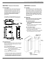
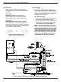
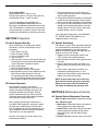
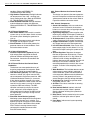
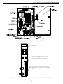
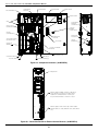
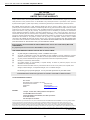
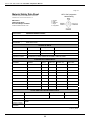
CD–15G ALL MODELS
CD–25G ALL MODELS
Installation & Operations Manual
3580 Sueldo Street, San Luis Obispo, CA 93401 | 800.676.1335 | [email protected] | www.delozone.com
4-0558 Rev.F
Genesis CD–15G and CD–25G Installation & Operations Manual
TABLE OF CONTENTS
SECTION 1 General Information
SECTION 4 Maintenance & Service
1A. Description................................................................1
1B. Specifications............................................................1
4A. System Electro-Mechanical Overview..................... 3
4B. PM Schedule............................................................ 7
4C. Troubleshooting....................................................... 7
4D. Contact Information.................................................. 7
SECTION 2 Installation
2A. Location.....................................................................1
2B. Mounting...................................................................1
2C. Electrical...................................................................2
2D. Plumbing...................................................................2
SECTION 5 Replacement Parts & Order Info
5A. Ordering Information................................................ 7
Warranty...................................................................... 8
SECTION 3 Operation
3A. Initial System Start-Up..............................................3
3B. Normal Operation......................................................3
3C. System Shut-Down...................................................3
Appendix
Appendix "A" (Safety) .................................................... 9
Appendix "B" (Troubleshooting Guide) ........................ 15
ALL Genesis™ CD Ozone
Generators are NSF listed.
IMPORTANT SAFETY INSTRUCTIONS
Read and Follow All Instructions.
•
•
•
•
•
•
•
•
•
•
•
Read this manual completely before attempting installation.
Risk of Electric Shock. Install the ozone unit and any metallic plumbing associated with the unit at least
5 ft from the inside wall of tub or pool.
Risk of Electric Shock. Connect this ozone generator in accordance with the installation instructions.
Do not install within an enclosure that would restict ventilation.
(Applicable to cord/plug connected units only) Risk of electric shock. Connect only to a properly grounded, grounding type receptacle.
Do not bury cord.
Warning – To reduce the risk of electric shock, replace damaged cord immediately.
Follow all applicable electrical codes.
Electric shock hazard. Be sure to turn power OFF at power source before any service work is performed.
Failure to do so could result in serious injury or death.
Warning – Short term inhalation of high concentrations of ozone and long term inhalation of low
concentrations of ozone can cause serious harmful physiological effects. DO NOT inhale ozone gas
produced by this device.
For your safety, do not store or use gasoline, chemicals or other flammable liquids or vapors near this
or any other appliance.
A spontaneous and violent ignition may occur if oil, grease or greasy substances come in contact with
oxygen under pressure. These substances must be kept away from oxygen regulators, cylinder valves
tubing and connections, and all other oxygen equipment.
SAVE THESE INSTRUCTIONS!
Genesis CD–15G and CD–25G Installation & Operations Manual
SECTION 1 General Information
SECTION 2 Installation
1A. Description
2A. Location
Genesis™
The
Corona Discharge series ozone generator described in this manual is designed to provide the benefits of ozonated water in an environmentally safe and effective manner. The high quality, specially engineered components
ensure efficient ozone output and reliable performance.
The Genesis™ CD ozone generator is safe and harmless to your equipment if installed properly.
2B.Mounting
24.1 613
A
12.3 311
A
DIM "A" = 6 [152] MIN CLEARANCE
11.7 297
4.0 102
MIN. CLEARANCE
(IF WALL MOUNTED) 4.0 102
Figure 1
1B.Specifications
2B-2. Floor Mount Option
1.Use the four 1/4"-20 bolts with washers to secure feet to bottom of cabinet.
2.Stand upright and securely fasten to concrete slab using appropriate anchors and bolts.
39.2 995
MOUNTING
BRACKETS (2)
NOTE: Do not remove compressor packing material until unit has been mounted.
2B-1. Wall Mount Option
1.Attach two mounting brackets to wall using anchors appropriate for mounting surface.
See Figure 2.
2.Using 1/4"-20 bolts (with washers as shown) secure generator to mounts.
DOOR SWING
R24.5 621
24.4 620
CD–15G amd CD–25G are designed for either floor or wall mounting in a clean, protected area, either indoors or outdoors. Locate generator out
of reach of sprinklers or drainage spouts. Allow sufficient access for maintenance and all tubing and electrical wires. Generators must not be
placed in locations where ambient ozone levels exceed 0.01 PPM.
1B-1. For detailed specifications refer to the ozone generator specification label located on the inside of the door on the unit.
1B-2. Location Requirements*:
Mounting: Floor or wall mount in a clean, protected
area using supplied brackets.
Ventilation: Room should provide 6 air changes per hour
Ambient Temp.: 40–100˚F (5–38˚C)
*Protection from weather elements must be provided for outdoor installations. Operating outside of the recommended temp. ranges may result in damage not covered under the manufacturer’s warranty.
Figure 2: Wall Mount
1
Genesis CD–15G and CD–25G Installation & Operations Manual
2C.Electrical
Refer to the units specification label and local electrical codes for information on proper electrical connection.
120V Models
Main power circuit: Unit is supplied with a standard power cord. Plug cord into standard
120V grounded, gounding type receptacle only.
230V Models
Main power circuit: 230V models are supplied with an IEC 6032 C-14 Type power receptacle. A power cord, having at least a 10AMP rating, with a IEC 60320 C-13 Type plug and a country specific plug is required to power generator.
2D.Plumbing
Ozone gas is introduced to the circulation line using a venturi injector. Suction developed by the venturi allows the generator to operate safely under vacuum. See installation manual for MX-601-XX
for proper venturi installation.
2D-1. Ozone Gas Line
1.Connect ozone tubing to generator outlet fitting.
(3/8" stainless steel compression fitting.)
2.Connect opposite end of ozone tubing to injector suction port. (Suction port fitting: 3/8" stainless steel compression fitting.) See Figure 4.
Figure 3: Country Specific Plug
(Australia shown for reference only)
NOTE: The ozone gas supply line must be
made of Teflon or stainless steel and have a back flow prevention device (such as a check valve) installed between the ozone generator cabinet and the point of injection to prevent water from backing up into the generator system. An ozone supply check valve is included with the MX–601–XX system.
Figure 4: Plumbing Schematic - Example of Swimming Pool Application
2
Genesis CD–15G and CD–25G Installation & Operations Manual
2D-2. Cooling Water
Cooling Water Flow: .1 Gpm (.4 Lpm)
Colling water Pressure: 15–40 psi (103–275 kPa)
Cooling Water Temp.: 5–90˚F (10–32˚C)
1/4" FPT connections are supplied on the generator. See Figure 4, 5a, 6a. Be sure that
the tubing is appropriately matched with the marked inlet and outlet ports. Carefully match and connect to water plumbing as shown in Figure 4. Alternate method using connections at injector may be used.
1.The system will not start-up if the door is not secured. A door interlock switch is incorporated into the system enclosure.
2.If the optional ORP/DO3 controller is installed the system will not produce ozone if the measured level is already above the setpoint of the controller.
3.The system will not produce ozone if there is not enough vacuum being generated by water flow through injector. The red "Vacuum" light will go out when proper vacuum is attained.
SECTION 3 Operation
3A.Initial System Start-Up
3C.System Shut-Down
The Genesis™ Corona Discharge ozone generator is a specialized water cooled device that must be properly protected during shut-down/storage periods.The following sequence of steps must be used for servicing or for storage.
1.Toggle the main system power switch to the “OFF” position to shut-down generator.
2.Close the ozone isolation valve to prevent water back flow.
3.After the generator has been shut-down, the process water circulation pump may be turned off.
4.If the system is going to be shut-down and stored during freezing weather, it is very important that the cooling water be drained to protect it from rupture or damage.
Upon completing all of the generator system connections, you are ready to begin start-up procedures.
1.Check electrical fittings.
2.Check for proper voltage.
3.Turn on circulation pump.
4.Check for leaks.
5.With the ozone isolation valve closed, adjust the injector bypass valve and/or filtration sidestream valve to flow water through the injector.
6.Check cooling water.
7.Open the ozone isolation valve.
8.Turn main power switch to "ON" position.
9.Adjust injector by-pass to attain required vacuum. (Red "Vacuum" light will go out.) Gas flow (as indicated by the flow meter on the door of the unit) should correspond with the rating listed for the specific model on the specification label.
NOTE: Process water flow must not be shut- down when the ozone generator is operating. Doing so may cause water to backflow into
the system and damage the generator cells.
3B.Normal Operation
With the power switch on, the system’s compressors and cooling fans will start-up, the oxygen concentrator will begin operating, and the output solenoid valve will open. With the injector adjusted to attain the correct gas flow, the ozone generator should be producing ozone and injecting it into the process line.
Both (2) green indicator lights should be lit. If an optional ORP Controller is installed, it should be displaying a reading from the sensor probe and will automatically cycle the generator on and off as needed to maintain water quality. Residual ORP levels will vary per application.
However, the system will not start under any of
the following conditions:
If you experience complications, see APPENDIX "B", TROUBLESHOOTING GUIDE or call
1-800-676-1335 for assistance.
SECTION 4 Maintenance & Service
4A.System Electro-Mechanical Overview
Refer to Figure 5a and 6a for component locations.
4A-1. Indicator Lights
1.Main Power: Green light indicates that power is being supplied to the ozone generator.
2.Ozone Power: Green light indicates that power is being supplied to the high voltage Corona Discharge circuits and that ozone is being produced.
3.Vacuum: Red light indicates a low vacuum fault 3
Genesis CD–15G and CD–25G Installation & Operations Manual
4A-5. External Devices that Control System Power
The devices turn power to the ozone generator on or off. Examples of such devices would be an ambient ozone monitor or flow switch. Refer to Figure 5b and 6b for connection details.
condition. (Refer to APPENDIX "B", TROUBLESHOOTING GUIDE.)
4.High Coolant Temperature: Red light indicates cell temperature is over 110F - resulting from loss of cooling water flow. (Refer to APPENDIX "B", TROUBLESHOOTING GUIDE.)
5.Water Backflow Detected: Red light indicates water backflow from injector into generator. (Refer to APPENDIX "B", TROUBLESHOOTING GUIDE.)
4A-6. Internal Components
1.Ozone Cell Assembly: Cells are made of two aluminum halves. Enclosed in the aluminum halves are a ceramic tube, coil type high voltage electrode and a teflon rod.
2.High Voltage Supply(s): Power supplies raise incoming line voltage and frequency to deliver it to the cells. Each power supply is rated at 100W.
3.Air Compressors: Compressors produce and supply compressed air to oxygen concentrator.
4.Oxygen Concentrator: Supplies concentrated, dry, oxygen feed gas to the ozone generator.
5.Low Limit Vacuum Switch: If the vacuum in the ozone output supply line falls below 1.5 in. Hg the switch will open causing the system to shut down.
6.Vacuum Regulator: Regulates the oxygen flow into the generator cell based on a vacuum setpoint (factory set to 3-5 in. Hg). When the sufficient suction is being developed by the injectors downstream the regulator will allow full flow to pass. As suction is reduced, flow is restricted proportionally to maintain the vacuum set point. If suction is lost completely, flow is
cut off.
7.Water Backflow: The backflow detector senses water present in ozone tubing in generator. If water is detected, system will close solenoid valve to prevent additional water backflow from occuring. Water in the generator will cause severe damage to the high voltage electrodes.
8.Ventilation Fan: Cooling fan operates when main power switch is “ON”.
9.Air Filter: Filter cleans ventilation air entering the enclosure.
10. Door Interlock Switch: Interlock switch will shut down entire system if door is opened. Securing the door will bring the system back
into operation.
11. Relay Panel: Contains control relays for system interlocks, indicator lights and main power control.
12. Hour Meter: Indicates total system operating time in hours.
4A-2. External Components
1.Main Power Switch: Power switch is used for system start-up and shut-down. Switch activates the control system allowing the generator to
start up.
2.Flowmeter: Flowmeter controls and indicates the oxygen flow through the system.
3.Circuit Breaker: Circuit breaker protects the generator from over current conditions. Push
the breaker button to reset.
4A-3. Internal Components
1.Variable Output Switch (optional): Adjusts high voltage power supplied to the ozone generator module controlling ozone output concentration. Located on the outside of the enclosure door.
4A-4. External Devices that Control Ozone Production
The devices turn ozone production on or off based on programmed level set points. Refer
to Figure 5b and 6b for connection details.
1.ORP Controller (optional): The ORP controller receives a millivolt (mV) signal from the ORP sensor mounted in the process water line. ORP (Oxidation-Reduction Potential) is a measure of the relative oxidation strength of the water.
As ozone is added to the water system the ORP level will rise. As ozone is used up in the water system the ORP level will drop. The ORP controller continuously analyzes the sensor signal, compares it to the setpoint that has been programmed, indicates the ORP level on the digital display, and relays the signal to the ozone generator.
2. Dissolved Ozone Monitor (optional): Monitoring system designed for the continuous measurement of ozone gas in solution. The operating range of the system may be selected by the user from 0-2.00 PPM or from 0-20.00 PPM. The basic sensing element used is polarographic membraned sensor which measures ozone directly.
4
Genesis CD–15G and CD–25G Installation & Operations Manual
Figure 5a: Component Locations (ALL MODELS EXCEPT –50)
Relay Panel
Remove jumper if ORP controller or dissolved
ozone monitor is used. Connect dry contact
leads from controller/monitor or leave open
if 5 pin external interface connector is used.
Remove jumper and connect dry contact leads if
external device is used. (ambient ozone, flow switch,
etc.)
Figure 5b: Connection Details for External Control Devices (ALL MODELS EXCEPT –50)
5
Genesis CD–15G and CD–25G Installation & Operations Manual
AIR COMPRESSOR
COMPRESSOR
AIR FILTER
DOOR SWITCH
HOUR METER
RELAY PANEL
ON/OFF SWITCH
FANS
5 PIN EXTERNAL
INTERFACE
CONNECTOR
HIGH VOLTAGE
POWER SUPPLIES
OPTIONAL
VARIABLE
OUTPUT SWITCH
OXYGEN
CONCENTRATOR
INDICATOR
LIGHTS
VACUUM REGULATOR
& SOLENOID VALVE
FLOW METER
RECEPTACLE
IEC 60320 C-14
CIRCUIT
BREAKERS (2)
OZONE CELL
ASSEMBLY
VACUUM & PRESSURE
SWITCHES
BACK FLOW PREVENTER
& SOLENOID VALVE
COOLING WATER OUT
COOLING WATER IN
OZONE OUT
AIR INTAKE SCREENS (3)
Figure 6a: Component Locations (–50 MODELS)
K3
Relay Panel
K5
K1
K2
K4
Remove jumper if ORP controller or dissolved
ozone monitor is used. Connect dry contact
leads from controller/monitor or leave open
if 5 pin external interface connector is used.
Remove jumper and connect dry contact leads if
external device is used. (ambient ozone, flow switch,
etc.)
Figure 6b: Connection Details for External Control Devices (–50 MODELS)
6
Genesis CD–15G and CD–25G Installation & Operations Manual
4B.Preventative Maintenance Schedule
4C.Troubleshooting
See APPENDIX "B", TROUBLESHOOTING GUIDE
NOTE: Knowledge of electrical applications is required for trouble shooting. Contact a certified electrician if you are unsure of your ability to service the equipment. If any condition persists,
call 1-800-676-1335 for technical assistance.
Regular maintenance should be performed to avoid damage to the system, more costly repairs and to keep the warranty active. For instance, the compressor should be rebuilt every 8,750 hours to prevent the reduction in air-pressure and flow.
If the compressor is not rebuilt, oxygen concentrator sieve beds will become plugged and unusable, creating more costly problems. If the generator cells are not cleaned or replaced annually, a lower ozone output will result.
4D.Contact Information
DAILY:
Check ozone generator for proper operation.
- Make sure no red indicator lights are lit.
- Make sure flow meter is indicating proper
air flow.
For Technical assistance:
Call: 1-800-676-1335 ext. 293
Email: [email protected]
Visit: www.delozone.com
SECTION 5 Replacement Parts &
Order Information
MONTHLY:
1.Inspect compressor air filter.
- Replace quarterly
2.Remove and clean air filter or intake screens See Figure 7.
- Remove filter cover plate to access filter.
- Rinse filter in warm, soapy water and blow dry.
- Replace filter.
- For the CD–15GV–50 and CD–25GV–50, remove and clean intake screens.
3.Perform general cleaning of cabinet interior.
5A.Ordering information
EVERY 8,750 HOURS:
1.Rebuild compressor. Kit Avaiable. See Section 5 for ordering information.
2.Replace/Service Check Valve(s) and Solenoid Valves.
3.Replace ozone cell O-rings and inspect ozone cells.
For replacement parts call DEL at 1-800-676-1335.
Be prepared with the following information:
• Customer Name
• Customer Address
• DEL Model Number
• DEL Serial Number
• Date Purchased
• Proof of Purchase
Intake Screen
bottom of cd cabinet
Figure 7: Filter or Intake Screen Removal for Cleaning
7
DETAIL B
Genesis CD–15G and CD–25G Installation & Operations Manual
DEL OZONE
COMMERCIAL PRODUCT
LIMITED TWO YEAR WARRANTY
The limited warranty set forth below applies to products manufactured by DEL OZONE – 3580 Sueldo Street, San Luis
Obispo, California 93401, and sold by DEL OZONE or its authorized dealers. This limited warranty is given only to the first
retail purchaser of such products and is not transferable to any subsequent owners or purchasers of such products.
Systems sized 65 grams or greater require factory commissioning and startup to maintain warranty as set forth below.
DEL OZONE warrants that DEL or DEL authorized dealers will repair or replace, at DEL’s option, any part of such
products proven to be defective in materials or workmanship within two (2) years of the date of receipt. Parts are covered
under the two (2) year warranty when and only when the stated maintenance requirements are met. Contact tanks and
degas valves have a ninety (90) day warranty. Compressor(s) must be maintained per operation and maintenance
manual. Required maintenance includes a compressor rebuild after one (1) year or every 8,760 hours, which ever is
reached first. Warranty does not include parts for compressor(s) rebuild kit(s), or other consumable items. See owner’s
manual for complete maintenance details. This Warranty specifically excludes any components not manufactured by DEL
OZONE that are external to the products covered, such as pumps, air compressors, monitors, tanks, or related
components. DEL OZONE will assist with warranty claims for such components purchased through DEL OZONE; limited
to the extent of the manufacturer’s standard warranty. ANY REPAIR OR REPLACEMENT WILL BE WARRANTED ONLY
FOR THE BALANCE OF THE ORIGINAL TWO (2) YEAR WARRANTY PERIOD
.
NOTE: USE ONLY DEL AUTHORIZED DEL REPLACEMENT PARTS. USE OF ANY OTHER PART(S) WILL VOID
THIS WARRANTY.
Any replaced parts must be returned to DEL OZONE for warranty evaluation.
THIS LIMITED WARRANTY DOES NOT INCLUDE ANY OF THE FOLLOWING:
(a)
(b)
(c)
(d)
(e)
(f)
Any labor charges for troubleshooting, removal, or installation of such parts.
Any repair or replacement of such parts necessitated by faulty installation, improper maintenance, improper
operation, misuse, abuse, negligence, accident, fire, flood, repair materials, and/or unauthorized accessories.
Any such products installed without regard to required local codes and accepted trade practices.
Damage to unit caused by water backflow;
Any implied warranty of merchantability or implied warranty of fitness for particular purpose, and such
warranties are hereby disclaimed.
DEL Ozone shall not be liable under any circumstances for loss of use of such product, loss of profits, direct
damages, indirect damages, consequential damages, and / or incidental damages.
This warranty gives you specific legal rights. You may have other rights which vary from state to state.
Extended Warranties and Service Agreements are available. Contact DEL for additional details.
TO OBTAIN WARRANTY SERVICE:
DEL OZONE
3580 Sueldo, San Luis Obispo, CA 93401
Customer Service Number:
(800) 676-1335
Fax Number:
(805) 541-8459
E mail
[email protected]
PROVIDE:
1. Project, contact name, mailing address and telephone.
2. Installer/Mechanical Contractor.
3. Unit Part Number, Serial Number, and date of purchase.
4. The date of failure.
5. A description of the failure.
After this information is provided, DEL Ozone may release a RETURN GOODS AUTHORIZATION (RGA) NUMBER. After receiving the RGA number
the part in question must be returned to DEL Ozone, freight prepaid, with the RGA number clearly marked on the outside of the package. All
preauthorized defective parts must be returned to DEL Ozone within thirty (30) days. Under no circumstances may any product be returned to DEL
Ozone without prior authorization. Returns without the assigned RGA number on the outside of the package will be refused and shipped back to the
sender at their expense. Upon receipt of preauthorized returned goods, DEL Ozone will repair or replace, at DEL Ozone’s option, the defective product(s)
and return them (freight prepaid for products under warranty). Buyer’s acceptance of the product and use thereof constitutes acceptance of these terms.
4-1370-01_Rev.D
8
Genesis CD–15G and CD–25G Installation & Operations Manual
APPENDIX “A”
SAFETY
9
Genesis CD–15G and CD–25G Installation & Operations Manual
OZONE
Material Safety Data Sheet
SECTION I: MATERIAL IDENTIFICATION
IDENTITY:
OZONE (Gaseous)
FORMULA: O3
ISSUED:
February, 1992
REVISED:
March, 2009
Description (origin/uses):
Occurs in atmosphere from UV light action on oxygen at high altitude. Commercially obtained by
passing air between electrodes carrying a high voltage alternating current. Also found as a by-product in welding areas, high
voltage equipment, or UV radiation.
Ozone is used as an oxidizing agent in air and water disinfection: for bleaching textiles, oils, and waxes; organic synthesis as in
processing certain perfumes, vanillin, camphor; for mold and bacteria control in cold storage.
Cautions:
A powerful oxidizing agent, ozone generally exists as a gas and is highly chemically reactive. Inhalation produces
various degrees of respiratory effects from irritation to pulmonary edema (fluid in lungs) as well as affecting the eyes, blood, and
central nervous system.
Manufacturer/Supplier: On-site generation, equipment available from various suppliers, including:
DEL Ozone
Phone: (805) 541-1601
3580 Sueldo Street
FAX: (805) 541-8459
San Luis Obispo, CA 93401
SECTION II: INGREDIENTS AND HAZARDS
Ozone, CAS No. 10028-15-6: NIOSH RTECS No. RS8225000
1991 OSHA PELs
8-hr TWA: 0.1 ppm vol. (0.2 mg/m3)
15-min STEL: 0.3 ppm vol (0.6 mg/m3)
1991-1992 ACGIH TLV
Ceiling: 0.1 ppm (0.2 mg/m3)
1990 IDLH
10 ppm
1990 DFG (Germany) MAK
TWA: 0.1 ppm (0.2 mg/m3)
Category 1: Local Irritant
Peak Exposure Limit: 0.2 ppm
5 min momentary value, 8 per shift
1990 NIOSH REL
Ceiling: 0.1 ppm vol. (0.2 mg/m3)
Other Designations: Triatomic oxygen: CAS No. 10028-15-6, NIOSH RTECS No. RS8225000
SECTION III: PHYSICAL DATA
Boiling Point: . . . . . . .
Vapor Pressure: . . . . .
Vapor Density (AIR = 1):
Solubility in Water: . . .
-169° F
Melting Point: . . . . . . . .
% Volatile by Volume: . .
Molecular Weight: . . . . .
pH: . . . . . . . . . . . . . . . .
Critical Temperature: . .
>1 ATM
1.6
0.49 ml @ 32° F (0° C),
3 ppm @ 20 ° C
-315.4° F (-193° C)
100%
48 Grams/Mole
Not Listed
10.22° F (-12.1° C)
Appearance and Odor: Colorless to blue gas (greater than -169° F): characteristic odor often associated with electrical sparks or
lightning in concentrations of less than 2 ppm and becomes disagreeable above 1-2 ppm. CAUTION: Olfactory fatigue develops
rapidly, so do not use odor as a preventative warning device.
SECTION IV: FIRE AND EXPLOSION HAZARD DATA
Flash Point: . . . . . . . .
Extinguishing Media: .
Nonflammable
Use large amounts of water spray or fog to put out fires involving ozone. Use appropriate fire-fighting
techniques to deal with surrounding material.
Special Fire Fighting Procedures:
Wear a self contained breathing apparatus with full face pieces operated in a pressuredemand or other positive-pressure mode.
Unusual Fire/Explosion Hazards: Decomposition of ozone into oxygen gas, (O2), can increase strength of fire.
SECTION V: REACTIVITY DATA
Stability: Ozone is not stable. Hazardous polymerization cannot occur.
Chemical Incompatibilities: Ozone is chemically incompatible with all oxidizable materials, both organic and inorganic.
Conditions to Avoid:
Ozone is unstable at room temperatures and spontaneously decomposes to oxygen gas. Avoid ignition
sources such as heat, sparks, and open flame. Keep away from strong reducing agents and combustible materials such as
grease, oils, and fats.
Products of Hazardous Decomposition: Ozone spontaneously decomposes to oxygen gas, even at room temperatures.
4-0697_ Rev.B
10
Genesis CD–15G and CD–25G Installation & Operations Manual
SECTION VI: HEALTH HAZARD DATA
Carcinogenicity: Ozone is not listed as a carcinogen by the NTP, IARC, or OSHA.
Primary Entry: Inhalation
Target Organs: Respiratory system, eyes, blood.
Summary of Risks: There is no true threshold limit and so no exposure (regardless of how small) is theoretically without effect
from ozone’s strong oxidative ability. Ozone passes straight to the smallest bronchioles and alveoli and is not absorbed by
mucous membranes along the way. Initial small exposure may reduce cell sensitivity and/or increase mucous thickness
producing a resistance to low ozone levels. Short exposure to 1-2 ppm concentrations causes headache as well as irritation to
the respiratory tract. but symptoms subside when exposure ends. High concentrations of ozone produce severe irritation of the
eyes and respiratory tract. Exposure above the ACGIH/OSHA limits produce nausea, chest pain, coughing, fatigue, reduced
visual acuity, and pulmonary edema. Symptoms of edema from excessive exposure can be delayed one or more hours.
Inhalation of >20 ppm for an hour or more (>50 ppm for 1/2 hour) can be fatal.
Acute Effects: Acute damage from ozone appears to be mainly from its oxidizing effect on contact with tissue.
Chronic Effects: Respiratory disease. Deleterious effects on lungs and acceleration of tumors have been reported.
Medical Conditions Generally Aggravated by Long-Term Exposure: History of respiratory or heart disorders.
First Aid: Remove from ozone containing air, get prompt medical help*, administer oxygen if necessary.
Eye Contact - Gently lift eyelids and flush eyes continuously with flooding amounts of water for 15 minutes or until transported to a
medical facility*.
Inhalation - Remove exposed person to fresh air, support breathing, administer humidified oxygen as needed, get medical help*.
Ingestion - Highly unlikely since ozone is a gas until -169° F,
* GET MEDICAL ASSISTANCE = APPROPRIATE IN-PLANT, PARAMEDIC, or COMMUNITY. Get prompt medical assistance for
further treatment, observation, and support after first aid.
SECTION VII: PRECAUTIONS FOR SAFE HANDLING AND USE
Steps to be Taken in Case of Spill/Leak:
1.
2.
3.
4.
Discontinue production
Isolate and vent area
Immediately notify personnel
Deny entry
5. Follow applicable OSHA regulations
Disposal:
Provide ventilation to dilute and disperse small amounts of ozone (below OSHA PELs) to outside atmosphere. Follow
federal, state, and local regulations.
Handling/Storage Precautions: Ensure proper personnel training and establish emergency procedures.
SECTION VIII: CONTROL MEASURES
Respiratory Protection: High Level (>10 ppm) - Self Contained Breathing Apparatus: MISH/NIOSH approved.
Low Level (0.3 - 10 ppm) - Canister Type (carbon) respirator may be used.
Eye Protection: Wear chemical safety goggles if necessary to work in high ozone (>10 ppm).
Skin Protection: Effects of ozone on skin are minimal to non-existent.
Ventilation: Provide general and local exhaust ventilation to dilute & disperse small amounts of ozone into outside atmosphere.
SECTION IX: SPECIAL PRECAUTIONS AND COMMENTS
Storage Segregation:
Prevent ozone from coming into direct physical contact with strong acids or bases or with strong
oxidizing/reducing agents.
Engineering Controls:
Install ventilation systems capable of maintaining ozone to concentrations below the ACGIH/OSHA
exposure limits (see sect. II). Install ambient ozone monitor(s) configured to shut down ozone equipment and turn high speed
ventilation on.
4-0697_ Rev.B
11
Genesis CD–15G and CD–25G Installation & Operations Manual
Page 1 of 3
Material Safety Data Sheet
NFPA 704 Designation
Hazard Rating
This MSDS complies with OSHA’s Hazardous Communication
Standard 29 CFR 1910.1200 and OSHA form 174.
4 = Extreme
3 = High
2 = Moderate
1 = Slight
0 = Insignificant
DEL Ozone
3580 Sueldo Street
San Luis Obispo, CA 93401
Product Information 805-541-1601
Product Name
AQUEOUS OZONE SOLUTION
Chemical Name
DISSOLVED OZONE GAS IN WATER 0 TO 2 PPM
Product Description
AQUEOUS SOLUTION OF OZONE DISSOLVED IN POTABLE WATER
D.O.T. Shipping
Classification
NON REGULATED
I PHYSICAL DATA
Boiling Point
212 F
Freezing Point
32 F
Specific Gravity
1.0
Solubility in Water
COMPLETE
Evaporation Rate
APPROX 1
Physical Form
LIQUID
Appearance & Odor
COLORLESS (CLEAR) WATER WITH FRESH, ASEPTIC ODOR
II HAZARDOUS INGREDIENTS
MATERIAL
HAZARD
CAS #
% BY WT
ACGIH TLV
OSHA PEL
None
III FIRE AND EXPLOSION HAZARD DATA
Flash Point
NA
Flammable Limits in
Air
Method NA
NON APPLICABLE
Extinguishing Media
NON APPLICABLE
Unusual Fire &
Explosion Hazards
Special Fire Fighting
Procedures
NONE
Auto Ign. Temp.
NA
Lower
Upper
NA
NA
NONE
4-1444-01_Rev.B
12
Genesis CD–15G and CD–25G Installation & Operations Manual
Page 2 of 3
Material Safety Data Sheet
Cont.
AQUEOUS OZONE SOLUTION
Product Name
IV HEALTH HAZARD DATA
Threshold Limit Value
NOT DETERMINED
Route of Exposure
Inhalation
Ingestion
Skin
Eye
Not Hazardous
Eye Contact Hazard
Exposure may cause mild eye irritation, but is not expected.
Ingestion Hazard
Not Hazardous
Inhalation Hazard
Inhalation is not likely to be a primary route of exposure but could become irritating if
aerosols are exposed to individual for extended period of time.
Skin Contact Hazard
No skin irritation is expected from short term exposure.
Skin Absorption Hazard
No published data indicates this product is absorbed through the skin.
Effects of Acute
Exposure
Mild skin or eye irritation.
Effects of Chronic
Exposure
Repeated exposure of the skin to concentrated product should be avoided to prevent
irritation and drying of the skin.
V EMERGENCY AND FIRST AID PROCEDURES
Eye Contact
If exposure to water containing aqueous solution of ozone causes irritation to eyes, flush eyes with
plenty of clean, ozone free, running water for at least 15 minutes, lifting the upper and lower lids
occasionally. Remove contact lenses if worn. Seek medical attention if irritation persists.
Skin Contact
Not likely to become irritated unless repeatedly exposed to large volumes of material. If irritation
develops, rinse affected area with ozone free potable water. If irritation continues seek medical
advice.
Inhalation
Inhalation of mists could lead to irritation of lungs. If symptoms develop, move individual away from
exposure and into fresh air. If symptoms persist, seek medical attention.
Ingestion
NA
VI REACTIVITY DATA
Incompatibility
(Materials to Avoid)
Natural rubber (may degrade, or “dry”, rubber components over extended periods of exposure)
Conditions
to Avoid
NONE KNOWN
Hazardous
Decomposition
NONE
Stability
STABLE
UNSTABLE
Hazardous Polymerization
MAY OCCUR
WILL NOT OCCUR
4-1444-01_Rev.B
13
Genesis CD–15G and CD–25G Installation & Operations Manual
Page 3 of 3
Material Safety Data Sheet
Product Name
Cont.
AQUEOUS OZONE SOLUTION
VII SPILL OR LEAK PROCEDURES
Steps To Be Taken
If Material Is Released
Or Spilled
NONE
Waste Disposal
Method
DISPOSE OF THE SAME AS POTABLE RINSE WATER
VIII SPECIAL PROTECTIVE INFORMATION
Respiratory Protection
(Specify Type)
Ventilation
NOT REQUIRED FOR NORMAL USE OF THIS PRODUCT
Local
Exhaust
PREFERABLE
Special
NA
Mechanical
(general)
OK
Other
NA
Protective Gloves
NOT REQUIRED
Eye Protection
NOT REQUIRED
Other Protective
Equipment
NOT REQUIRED
IX SPECIAL PRECAUTIONS
Precautionary
Labeling
Certified testing of DEL Ozone systems by NSF (National Sanitation Foundation) has shown that
under normal conditions of use, aqueous solutions containing low levels of ozone gas dissolved in
potable water do not present a safety hazard when contact to the individual is incidental. When
used in a room with normal ventilation, levels of ozone gas being released into the air have been
shown by NSF to be well below the periodic exposure levels established by OSHA for worker
safety through the use of DEL’s ozone management technology.
Precautions To Be
Taken In Handling
Aqueous solutions of ozone in potable water should not be sprayed as an aerosol (i.e. >20psi) to
avoid releasing higher levels of ozone gas into the work area. The decay rate of ozone gas is a
function of temperature and exposure to organic material. Certified testing has shown that when
ozone gas has been properly dissolved in ambient temperature (or colder (33 – 70 °F)) potable
water at a level not exceeding 2 mg/l (ppm) using DEL’s ozone management technology, the rate
at which ozone is released from the water as ozone gas is below the PEL established for gaseous
ozone.
Rev. Date
03/26/09
This material safety data sheet is provided as an information resource only. It should not be taken as a warranty or representation for which the preparer
assumes legal responsibility. While we believe the information contained herein is accurate and compiled from sources believed to be reliable, it is the
responsibility of the user to investigate and verify its validity. The buyer assumes all responsibility of using and handling the product in accordance with
applicable federal, state, and local regulations.
4-1444-01_Rev.B
14
Genesis CD–15G and CD–25G Installation & Operations Manual
APPENDIX “B”
TROUBLESHOOTING GUIDE
15
Genesis CD–15G and CD–25G Installation & Operations Manual
TROUBLESHOOTING GUIDE
FOR DEL OZONE CD-15G & 25G SERIES
OZONE GENERATORS
This document is a guide to help troubleshoot problems that might arise in operation of the DEL Ozone
CD-15G & 25G Series ozone generators. It contains three main sections that when used together
provide a basic overview of the ozone generator layout, troubleshooting table for common problems, and
electrical, pneumatic, and hydraulic order diagrams. If you still need help, call our Commercial Service
Department at 1-800-676-1335.
Note: Always disconnect the ozone generator from the power source before attempting service or repair.
Image 1: Ozone Generator Component Locations (CD-25GV model shown)
12
15
2
23
32
21
16
13
4
1
14
19
17
28
31
27
29
10
25
30
9
18
7
22
24
3
26
8
5
6
11
20
1. 5-Pin connector (not shown)
2. 12VDC power supply (optional)
3. Backflow prevention device (BFPD)
4. Brass orifice
5. Cabinet fan
6. Cabinet filter (not shown)
7. Circuit breaker
8. Compressor
9. Compressor air filter
10. Cooling block assembly
11. Cooling water in & out fittings
TSG CD-15G & 25G
12. Door switch
13. Flowmeter
14. Fuse
15. Hourmeter
16. Indicator lights
17. Oxygen concentrator
18. Oxygen solenoid valve
19. Ozone cells
20. Ozone output fitting
21. Ozone power supplies
22. Ozone solenoid valve
1 of 4
16
23. Power switch
24. Pressure relief valve
25. Pressure switch
26. S.S. check valve
27. Terminal block 1 (TB1)
28. Terminal block 4 (TB4)
29. Thermal switch (not shown)
30. Vacuum regulator
31. Vacuum switch
32. Variable ozone output control
(optional)
4-1529-01_Rev.A
Genesis CD–15G and CD–25G Installation & Operations Manual
Table 1: Troubleshooting
(for best results follow the table order)
Problem (Indication)
1. Unit does not start
Possible Cause
a. Unit is not supplied power
(main power light is off and no
sound is coming from the unit)
2. Unit is in vacuum fault
(vacuum light is on)
3. Unit is in high temperature fault
b. Unit door switch is open
c. Unit power switch is in off position
d. Unit circuit breaker is tripped
a. Inadequate vacuum is supplied to
unit
b. Unit S.S. check valve has failed
c. Unit vacuum switch has failed
d. Unit vacuum regulator requires
adjustment or has failed
a. Unit thermal switch has tripped
(high coolant temperature light is
on)
4. Unit is in backflow fault
(water backflow detected light is on)
5. Unit does not flow gas
(flowmeter at bottom of scale)
6. Unit ozone production does not
start
(both ozone power and vacuum
lights are off)
7. Unit does not provide effective
sanitation
(both main power and ozone power
lights are on)
b. Unit thermal switch has failed
a. Water has returned from injection
point and triggered unit back flow
float switch
a. Unit flowmeter valve is closed
b. Unit jumper(s) at TB1 are removed
(optional system control hookup, e.g.
flow switch and/or ambient O3)
c. Unit fuse is blown
d. Unit pressure switch is not active
e. Unit orifice is plugged
f. Unit solenoid valve(s) has failed
g. Unit flowmeter ball is stuck on
bottom of sight tube
h. Unit vacuum regulator requires
adjustment or has failed
a. Unit jumper at TB4 is removed
(optional external ozone control
hookup, e.g. ORP or dissolved O3,
directly wired or through 5-Pin)
a. Unit variable ozone output control
setting is too low (optional feature)
b. Leak in plumbing that dilutes
applied ozone dose
c. Low gas flow and/or low oxygen
concentration
d. Unit ozone cell has reached
service life or failed
e. Unit ozone power supply has failed
TSG CD-15G & 25G
2 of 4
17
Corrective Action
Connect unit to power source
Turn power source breaker on
Reset power source G.F.C.I.
Verify power source voltage is
within unit specification
Close unit door
Turn power switch on
Reset circuit breaker
Connect unit to vacuum source
(injector)
Adjust injector to provide more
vacuum
Fix leak or obstruction in plumbing
between injector and unit
Clean or replace S.S. check valve
Replace vacuum switch
Call service department for
assistance
Reduce supplied cooling water
temperature and/or increase flow
rate
Obstruction or scaling in cooling
block assembly (clean or replace)
Replace thermal switch
Disconnect ozone line between
injector and unit at ozone output
fitting, drain BFPD vessel, and
replace SS check valve
Adjust flowmeter valve open
Re-install jumper(s) and/or verify
system control(s) are operational
Replace fuse
Verify unit plumbing between
oxygen concentrator and pressure
switch is securely connected
Replace compressor air filter
Rebuild compressor
Replace oxygen concentrator
Clean or replace orifice
Clean or replace solenoid valve(s)
Repair or replace flowmeter
Call service department for
assistance
Re-install jumper and/or verify
external ozone control is
operational
If so equipped, increase ozone
output setting
Fix leak in plumbing (inside unit
and/or between unit and injector)
Replace unit compressor air filter
Clean or replace unit orifice
Clean or replace unit check valve
Rebuild unit compressor
Replace unit oxygen concentrator
Replace ozone cell
Replace power supply
4-1529-01_Rev.A
Genesis CD–15G and CD–25G Installation & Operations Manual
TSG CD-15G & 25G
3 of 4
18
4-1529-01_Rev.A
Genesis CD–15G and CD–25G Installation & Operations Manual
TSG CD-15G & 25G
4 of 4
19
4-1529-01_Rev.A
3580 Sueldo Street, San Luis Obispo, CA 93401 | 800.676.1335 | [email protected] | www.delozone.com
EPA Estab. No. 071472-CA-001