1
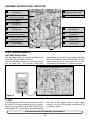
ASSEMBLY INSTRUCTIONS - DETECTOR
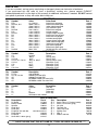
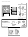
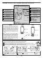
C6 - 100μF Lytic
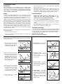
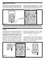
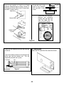
(see Figure B)
R8 - 100Ω Resistor
(brown-black-brown-gold)
R5 - 27kΩ Resistor
(red-violet-orange-gold)
T3 - IF Coil (black)
T1 - IF Coil (yellow)
TP3 - Test Point Pin
(see Figure A)
C4 - 10μF Lytic
(see Figure B)
TP5 - Test Point Pin
(see Figure A)
R11 - 3.3kΩ Resistor
(orange-orange-red-gold)
D1 - 1N4148 Diode
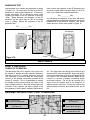
(see Figure E)
C9 - .02μF or .022μF Discap
(marked 203 or 223)
C15 - .001μF Discap
(marked 102)
R12 - 2.2kΩ Resistor
(red-red-red-gold)
C10 - .01μF Discap
(marked 103)
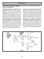
STATIC MEASUREMENTS
AGC ZERO SIGNAL BIAS
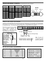
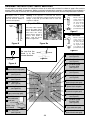
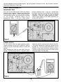
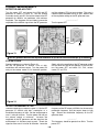
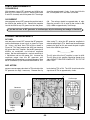
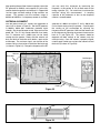
With the power turned OFF, connect the VOM to test
point three (TP3) as shown in Figure 12.
Check that the VOM is adjusted to read 9 volts DC and
turn the power ON. The voltmeter should read
approximately 1.5 volts DC. If your reading varies more
than .5 volts from this value, turn the power OFF and
check the polarity of D1, and resistors R11 and R5.
Also check that transformer T1 is properly installed.
V
Amps COM
Figure 12
V/Ω
GND
R15
T3 TEST
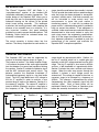
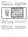
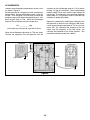
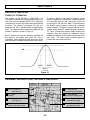
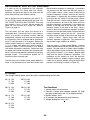
With the power turned OFF, connect the positive lead of
the VOM to TP5 and the negative lead to any ground.
Make sure that the VOM is set to read 9 volts DC and
turn the power ON. The voltage on the VOM should be
the same as your battery voltage or power supply
voltage. If not, turn OFF the power and check that T3
is properly installed.
If you do not have an RF generator, go to Section 3.
-17-