1
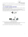
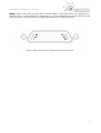
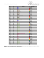
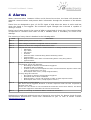
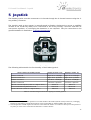
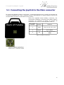
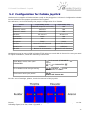
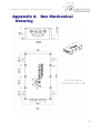
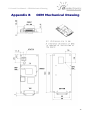
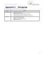
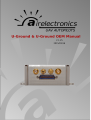
U-Ground User Manual -
Table of Contents
1 General System Introduction..............................................................................................3
1.1 Concept of system operation......................................................................................4
2 U-Ground.............................................................................................................................5
2.1 U-Ground and U-Ground OEM...................................................................................5
2.2 Power supply..............................................................................................................5
2.3 U-Ground Connections...............................................................................................5
2.3.1 U- Ground Main Connector.................................................................................5
2.3.2 Pressure sensors connections............................................................................8
2.3.2.1 U-Ground (Box) pressure connections........................................................8
2.3.2.2 U-Ground OEM pressure connections.........................................................8
2.3.3 Radio-link antenna connections..........................................................................8
2.3.3.1 U-Ground (Box) Radio-link connection........................................................8
2.3.3.2 U-Ground OEM Radio-link connection........................................................8
2.3.4 GPS antenna connections...................................................................................8
2.3.4.1 U-Ground (Box) GPS connection.................................................................8
2.3.4.2 U-Ground OEM GPS connection.................................................................8
3 Communications.................................................................................................................9
4 Alarms...............................................................................................................................10
4.1 Audible Signal...........................................................................................................10
5 Joystick..............................................................................................................................12
5.1 Connecting the Joystick to the Main connector........................................................13
5.2 Configuration for Futaba Joystick.............................................................................14
Appendix A Box Mechanical Drawing..................................................................................15
Appendix B OEM Mechanical Drawing................................................................................16
Appendix C Changelog........................................................................................................17
2
U-Ground User Manual - General System Introduction
1 General System Introduction
Airelectronics has developed a complete solution for both rotary and fixed wing UAVs. The
system is composed of:
•
U-Pilot or U-Pilot OEM
•
U-Ground or U-Ground OEM
•
U-See Software
U-Pilot manages and controls the vehicle from Take-off to Landing, being capable of controlling
any kind of aircraft including fixed wing, helicopters and multicopters.
U-Pilot is completely capable of following a flight plan with up to 200 real-time editable points.
Once the flight plan is loaded on U-Pilot, it is independent of operator instructions, and in case
of a communications failure, U-Pilot starts a Return Home and Land manoeuvre which would
safely land the UAV on the Runway Point.
Thanks to its versatility, U-Pilot can control any payload on board the UAV such as cameras,
parachutes or sensors. These devices can be real time controlled by a computer operator or by
U-Pilot automatically.
The FPGA technology used in U-Pilot and U-Ground allows the system to have several logic
working in parallel with the main processors. U-Pilot has working in parallel:
•
Up to 31 PWM (Pulse-Width Modulation) or GPIO (General Purpose Input / Output).
•
3 ADC inputs (Analogical Digital Converter) to monitor the voltages of 3 batteries on the
UAV.
•
4 serial ports RS232 to communicate with payloads, external magnetometers, etc.
•
A radio with up to 100 km1
•
GPS, dynamic and static pressure sensors, a magnetometer, gyroscopes and
accelerometers.
U-Pilot is built using a two parallel microprocessor approach:
•
One processor handling the state estimation and control of the UAV, using hardware
acceleration to calculate high speed algorithms.
•
A second processor handles of the mission at high level, communications with U-Ground
and the Payload.
•
The processors do not spend time handling low-level tasks, as these tasks are processed
in parallel by dedicated logic of the FPGA.
Due to the fact that those two processors are working in parallel and there is dedicated
electronics processing the serial ports, sensors, inputs and outputs, the system is capable of
recalculating its position, orientation and closing control loops at 1000 Hz. This control speed
provides a great navigation accuracy and control.
On the ground segment, Airelectronics has both U-Ground and U-See.
U-Ground is a ground station that mainly acts as a relay of command and data between U-Pilot
and U-See software. Besides acting as data relay, U-Ground provides useful information to UPilot such as U-Ground position and pressures. U-Ground hardware is also capable of handling a
Antenna tracking system.
1 Range may vary with the frequency band used. Default is 900 MHz but legal limitations in some countries may
change this.
3
U-Ground User Manual - General System Introduction
U-See software is a user friendly program that runs in any personal computer running Windows
or Linux.
Using U-See, the UAV operator can monitor the current state of the vehicle, control the UAV or
modify the vehicle mission in real time.
1.1 Concept of system operation
The system consists of an U-Pilot installed on an aircraft connected to a U-Ground through a
radio link. (See figure 1 attached below)
U-Ground has its own radio link to communicate with the U-Pilot and a RS-232 port to relay the
data and command between a PC running U-See and the U-Pilot on-board the vehicle.
Under certain circumstances such as aircraft integration and characterization, a Futaba Emitter
is recommended in order to provide manual override of the vehicle.
The mission operation team is usually formed by two people:
•
A External Pilot who will handle the Futaba Joystick in case a manual control of the UAV
is desired (specially during the development and adjustment phase).
•
A U-See operator that will command the mission using a computer.
When using the UAV for surveillance purposes, a camera operator is recommended.
4
U-Ground User Manual - U-Ground
2 U-Ground
The U-Ground hardware is the link between our U-Pilot and the computer running U-See that
finally controls the mission.
U-Ground hardware relays the data it receives from the U-Pilot through a serial RS-232
interface. This data is processed in U-See running on a standard PC which should have a RS232 port available (We include a USB to RS-232 converter in the installation kit).
U-Ground has an integrated GPS to track its own position and standard PWM outputs to allow
the steering of directional antennas towards the UAV to maintain a stable video link.
It also provides the manual override function, by connecting any standard Futaba transmitter
with a trainer port to the hardware. In that way, an external pilot can fly the UAV in a manual
mode (Refer to section 5, joystick) with the very familiar interface of a Futaba joystick, while
keeping all its functionality (exponential settings in control, mixtures, etc.)
2.1 U-Ground and U-Ground OEM
U-Ground can be acquired in two versions, the standard version, enclosed in an aluminium box,
and the OEM version that is not enclosed, ready to be embedded into the customer system.
Unless told otherwise, the explanations provided by this document are valid for both versions.
When different explanations are required, this document will state it.
2.2 Power supply
U-Ground power supply accepts voltages in a range from 6.0V to 24V.
CAUTION: Powering U-Ground at a voltage OUT of range can cause IRREVERSIBLE DAMAGE to
the system. Please read carefully this manual and do not hesitate to contact us
(www.airelectronics.es) if needed.
Typical power consumption about 4 Watt, but the power system should be prepared to
withstand 7 Watts peaks. This consumption will mean an intensity consumption of 0.8 Amp. at
6V or 0.4 Amp. at 12 V.
2.3 U-Ground Connections
This section provides the required information about U- Ground connections, including:
•
Main connector connections
•
Pressure connections
•
Radio-Link connections
•
GPS antenna connections.
2.3.1 U- Ground Main Connector
The aerial part of connector used for U-Ground is provided in the Installation Kit. Cables in the
aerial connector are colour coded. The following table describes the function of every pin in the
main connector in U-Ground and the corresponding colour coded cable in the supplied aerial
connector.
5
U-Ground User Manual - U-Ground
NOTE: Please, take into account than in these tables, Tx and Rx suffix are referred to UGround. This is: a line marked as “Comms Rx” is the pin dedicated to receive data from the
radio, and thus, must be connected to the sending pin in the radio connector.
6
U-Ground User Manual - U-Ground
PIN
I/O
1
2
3
4
5
6
7
8
9
10
11
12
13
14
15
16
17
18
19
20
21
22
23
24
25
26
27
28
29
30
31
32
33
34
35
36
37
38
39
40
41
42
43
44
45
46
47
48
49
50
51
In
In
DC in
GND
NC
NC
In
GND
NC
NC
GND
In
NC
NC
GND
NC
In
Out
In
DC in
Out
Out
NC
NC
NC
NC
NC
NC
NC
NC
NC
NC
NC
NC
NC
GND
Out
Out
Out
Out
Out
Out
Out
Out
NC
NC
NC
NC
NC
NC
NC
Function
ADC 2
ADC 1
VIN
Ground
Reserved
Reserved
Futaba Joystick
Ground
Reserved
Reserved
Ground
DGPS-TTL Correction
Reserved
Reserved
Ground
Reserved
RS232 comms Rx
RS232 comms Tx
ADC 3
VIN
Tracker Pan Servo
Tracker Tilt Servo
Reserved
Reserved
Reserved
Reserved
Reserved
Reserved
Reserved
Reserved
Reserved
Reserved
Reserved
Reserved
Reserved
Ground
Square Wave Audible Signal
Alarm 1
Alarm 2
Alarm 3
Alarm 4
Alarm 5
Alarm 6
Alarm 7
Reserved
Reserved
Reserved
Reserved
Reserved
Reserved
Reserved
Cable Colour
Black
Brown
Red
Orange
Yellow
Green
Blue
Purple
Grey
White
Black
Brown
Red
Orange
Yellow
Green
Blue
Purple
Grey
White
Black
Brown
Red
Orange
Yellow
Green
Blue
Purple
Grey
White
Black
Brown
Red
Orange
Yellow
Green
Blue
Purple
Grey
White
Black
Brown
Red
Orange
Yellow
Green
Blue
Purple
Grey
White
Black
Note: At least one GND has to be connected to ground, the other GND pins are optional. All the
GND pins are connected internally between them.
7
U-Ground User Manual - U-Ground
2.3.2 Pressure sensors connections
U-Ground has a single static pressure sensor. The static pressure tap may be left unconnected
if U-Ground environment is not sealed or pressurized. Otherwise it must be connected to the
ambient pressure.
The static pressure connection installation differs in U-Ground and U-Ground OEM. Depending
on your U-Ground version, you have to refer to the appropriate subsection.
2.3.2.1 U-Ground (Box) pressure connections
U-Pilot pressure connection is properly labelled on the front face of the box with the name
“STATIC”. The static pressure sensor can be left unconnected if U-Pilot environment is not
pressurized or sealed.
2.3.2.2 U-Ground OEM pressure connections
The OEM version of U-Ground exposes directly the static
pressure sensors. The sensor can be identified with the
attached image.
The static pressure sensor can be left unconnected if UPilot environment is not pressurized or sealed.
2.3.3 Radio-link antenna connections
The radio-link antenna connection depends on the version of U-Ground. Depending on your UGround version, please refer to the appropriate subsection.
2.3.3.1 U-Ground (Box) Radio-link connection
The radio-link antenna must be connected to U-Ground with an SMA-connector to the
connector labelled as “RADIO” in the front face of U- Ground box.
2.3.3.2 U-Ground OEM Radio-link connection
The radio-link antenna must be connected to the radio-module using and MMCX connector as
described in the mechanical drawing appendix.
2.3.4 GPS antenna connections
The GPS antenna installation depends on the version of U-Ground.
Ground version, please refer to the appropriate subsection.
Depending on your U-
2.3.4.1 U-Ground (Box) GPS connection
The GPS antenna must be connected to U-Ground with an SMA-connector to the connector
labelled as “GPS” in the front face of U-Ground box.
2.3.4.2 U-Ground OEM GPS connection
U-Ground OEM has two GPS exposed connectors:
•
UFL connector.
•
SMA connector.
The GPS antenna can be connected to any of the two connectors using the apropriate
connector but NOT BOTH simultanously. The location of the UFL and SMA connectors is
described in the mechanical drawings for the OEM version.
8
U-Ground User Manual - Communications
3 Communications
Communication between the U-Pilot and the U-Ground is done by a Radio Link with High noise
immunity, high reliability and a range up to 100 km.
All the settings regarding the radio configuration are configured by Airelectronics when the
units are produced, so you do not have to worry about the communications, it is completely
plug and play.
Available on the bands of 2,4 GHz, 1,4 Ghz, 900 MHz , 455 MHz and 869 MHz with channel
hopping.
In case you wish to use your own radio link, Airelectronics can supply you with a version of UPilot without a radio on board.
The data transmitted from the U-Pilot unit is then relayed to a computer through a RS-232
interface. The computer used must have an available RS-232 port or use a serial USB to RS-232
converter. This data is to be interpreted and presented to the end user through our U-See
software.
9
U-Ground User Manual - Alarms
4 Alarms
When communications between U-Pilot and U-Ground are active, the latter will decode the
downlink communications and present basic information through the activation of the Alarms
lines.
These lines are designed to give a 3.3V TTL signal of high when the alarm is active and low
when the signal is not toggled. The maximum signal strength the U-Ground is capable of
driving is 25 mA.
Typical use of these signal is the usage of LEDs or other kind of visual aids. If the required load
is expected to consume more than 25 mA, a MOSFET drive is mandatory to avoid circuit
damage.
The meaning of every alarm is detailed in the following table
Alarm
Active when:
Alarm 1
COMMs quality level is below 70%
Alarm 2
Some voltage is below the configured value for an alarm.
Alarm 3
Distance is above the configured threshold for alarm
Alarm 4
Autopilot has risen an alarm that is neither Distance or Voltage related. This includes:
•
GPS Alarm
•
Gyro Alarm
•
ACC Alarm
•
PS Alarm
•
Qd Alarm when communicating with a fixed wing vehicle
•
Joystick Alarm
•
Magnetometer Alarm when communicating with a rotary wing vehicle
•
Joystick Alarms
Alarm 5
System Is ready for flight.
In fixed wing system this indicates:
•
No voltage or distance related alarms triggered
•
3D GPS Fix with 6 satellites
•
At least once since the autopilot has been communicated the dynamic sensor was
seen to indicate above 2.5 me/s
•
No autopilot alarm risen ( except magnetometer )
In rotary wing this indicates:
•
No voltage or distance related alarms triggered
•
3D GPS Fix with at least 6 satellites
•
Magnetometer is online and magnetic module is within expected value
•
No autopilot alarm risen ( except dynamic sensor )
Alarm 6
System wants to return home.
This alarm will be triggered whenever a mission supervisor limit has been surpassed at
anytime in the past.
As the user can choose to over-command the automatic return home feature, this alarm
will remain triggered to remember the need to return home.
Alarm 7
System is executing an automatic Return and Home manoeuvre.
Airelectronics could have tailored your set of alarms for your project. So, please, check for extra
documentation Airelectronics could have transferred to you. In case of doubt. Contact
[email protected].
10
U-Ground User Manual - Alarms
4.1 Audible Signal
Besides toggling the corresponding line, the ground station will generate a square wave to be
feed into a square wave buzzer.
The audible tone generated at the time of writing (2014/09/03) are 3 beeps of half a second
duration and variable pitch in function of the toggled alarm.
An audible tone will be generated any time an alarms goes from deactivated to active. If more
than one alarm is triggered at the same time, the ground station will generate tones for every
one of the alarms in a sequential manner.
Audible tone is designed to be used as an addition to a visual feedback mechanism: Audible
tone attracts the attention of the operator and he checks the visual feedback panel.
Again, U-Ground will drive at most 25 mA at 3.3V TTL. As this is usually too weak to drive a
buzzer with enough power to be clearly audible, a MOSFET drive would be recommended for
the buzzer.
11
U-Ground User Manual - Joystick
5 Joystick
The Futaba joystick must be connected to U-Ground through the U-Ground harness using the 3way military connector.
The Joystick used on the system is manufactured by Futaba. Airelectronics serves a modified
version of the model T6J ready to be connected to the 3-way military connector and with its
own power regulator, so recharging the batteries is not required 2. The pin connection to the
ground Hardware is detailed on U-Ground Connections.
Figure 4: Joystick
The following table details the functionality of the Futaba Joystick.
STICK or SWITCH in FUTABA JOYSTICK
Mapping in Futaba T7CP
Mapping in Futaba T6J
Aileron command
Right Stick. Left/Right
Right Stick. Left/Right
Elevator Command
Right Stick. Up/Down
Right Stick. Up/Down
Rudder command
Left Stick. Left/Right
Left Stick. Left/Right
Throttle command
Left Stick. Up/Down
Left Stick. Up/Down
Manual override request (used as a digital switch)
Switch B.
Switch A
Roll command during Roulette mode
Wheel VR
Wheel VR
Switch D
Switch B
3
Camera Shooter (used as a digital switch)
Table 1: Channel usage and usual mapping in Futaba joystick
2 Some customers may be still in possesion of an older model of the emitter (Futaba T7CP). In that case, recharging
batteries is still needed. Configurations and use of the T7CP model are still described in this manual.
3 The autopilot has a PWM output reserved to be connected to the shutter of a camera to allow you to take pictures at
any time you want. This is referred in the manuals as “camera shooter”.
12
U-Ground User Manual - Joystick
5.1 Connecting the Joystick to the Main connector
To connect the Futaba emitter to U-Ground , a manufactured harness is usually served with the
U-Ground installation kit. If the customer needs to manufacture a custom harness, the pin-out
of the Futaba connector is described in this section.
Using the supplied aerial military connector, the
connections between U-Ground and Futaba military
connector (as detailed in Figure 5) should be
established as shown in following table (Table 2)
Pin in Futaba
Connector
Function
Connect to
1
GND
Pin 4, 8, 11, 15 or 36
2
Signal
Pin 7 (Blue)
3
Vin
6.5 -28V (Referred to
GND)
Table 2: Futaba connections
13
U-Ground User Manual - Joystick
5.2 Configuration for Futaba Joystick
Airelectronics supplies a Futaba emitter ready to be plugged to U-Ground. Configuration should
be not altered for the proper operation of the system.
For reference, we include hereby the proper configuration for a Futaba:
Feature
Proper Setting (T7CP)
Proper Setting (T6J)
PCM/PPM (depends on model)
N/A
Channel 5 switch
Switch D
N/A
Channel 7 switch
Switch B
N/A
All set to 0
All set to 0
Dual Rates
100%
N/A
Exponential
0%
0%
100%
100%
Normal for all channels
Normal for all channels
Inhibited
Inhibited
Normal in all channels
Normal in all channels
Modulation
Sub-Trim
End points
Reverse
Throttle-cut
Fail-safe
Modulation must be set to PCM in Futaba T7CP variant to work with U-Ground. In case you need
to adjust modulation, follow the following instructions
Open Basic menu, then open
PARAMETER.
for 1 second. (If ADVANCE,
again.)
or
to PARAMETER
Go to MODUL and change setting.
to MODUL
to PCM.
PCM flashes on screen
Close menu and cycle power.
Power Off. Power On.
For the rest of settings, please, check the manual of the joystick.
Please, check with the software (U-See) that the joystick sticks movement correspond to the
following figure (In U-See, View → Joystick ).
14
U-Ground User Manual - Box Mechanical Drawing
Appendix A
Drawing
Box Mechanical
15
U-Ground User Manual - OEM Mechanical Drawing
Appendix B
OEM Mechanical Drawing
16
U-Ground User Manual - Changelog
Appendix C
Changelog
This annex describes changes introduced to this document.
Date
Changes
2015/03/16
•
Chnaged pin Connections for Emitter.
2015/02/23
•
•
•
•
•
Updated version to 1.25
Added Mechanical Drawings
Added explanation for pressure and RF connectors.
Updated description of pins to match 51 pin connector.
Updated information about the Futaba Emitter model used.
2014/09/03
•
•
•
•
•
Version of document up to 1.24
Added pin-out for alarm signaling
Added pin-out for audible alarm
Added description of the visible alarms
Added Changelog table
17