1
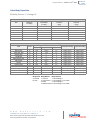
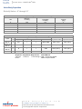
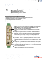
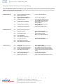
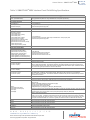
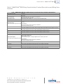
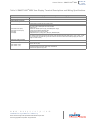
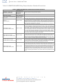
Control Valves - SMARTLINK® MRV
10-30.7-59
E - i - 3/14
50120624-001/
Operational Checkout
Apply power to the SMARTLINK® MRV System. If a SMARTLINK® MRV Interface Panel was purchased, switch the breaker
located on the lower rail of the Interface Panel to the ON (or up) position. The breaker switch will power all system components
including the SMARTLINK® Valve Actuators. Perform the following operational checkout prior to attempting burner light-off and
commissioning the system for burner operation:
1) Disable the burner system by turning the combustion blower off and manually turning off the pilot and main fuel supply.
2) Place the Mode switch of the Control Interface in its middle position. With all Valve Actuators wired, verify the Control Interface
Alarm light is off and the Run light is blinking indicating the system is in the Startup Mode. If the Control Interface alarm light is
on, see page 10-30.7-66 on troubleshooting and alarms, to determine the cause of the alarm and corrective actions.
3) Verify operation of each SMARTLINK® MRV relay output by using the procedures summarized in Table 10 (page 10-30.7-78).
If a MAXON MRV Interface Panel is provided, the Relay Output Interface (ROI) is factory-wired to the Control Interface and a
field wiring terminal block for easy access to the output contacts. The relay output terminals of the Control Interface are also
referenced in Table 10 to assist in operational checkout of systems with customer-supplied relays or a PLC-based burner
management system that controls burner startup (without the MAXON Relay Output Interface).
4) Turn on the combustion blower. Re-enable the burner management system but keep the pilot and main fuel supply turned off.
Verify that all combustion system safety interlocks are satisfied.
5) Power cycle SMARTLINK® MRV and verify the relay input commands from the burner management system properly drive
SMARTLINK® MRV to its purge and light-off states. If a MAXON SMARTLINK® MRV Interface Panel is provided, the Relay
Input Interface (RII) is factory-wired to the Control Interface and a field wiring terminal block. The lights of the Relay Input
Interface indicate when each input command relay is energized and the 4-20 mA output (OUT-/OUT+ terminals) can be
measured by a current meter to verify SMARTLINK® MRV has responded to the input command. When the burner
management system (or flame safety) issues a Purge Position Command, the PPC terminal of the Interface Panel is energized
and the Relay Input Interface (terminal #6) outputs a voltage greater than 22 VDC to the Control Interface input terminal RI1
(Relay Input #1). When a Light-Off Position Command is issued, the LPC terminal of the Interface Panel is energized and the
Relay Input Interface (terminal #5) outputs a voltage greater than 5 VDC to the Control Interface input terminal RI2 (Relay Input
#2). The following 4-20 mA output currents can be measured for each of the following SMARTLINK® MRV states: 1 mA=
Standby Positions; 2 mA = Purge Positions; 3 mA = Light-Off Positions.
w w w . m a x o n c o r p . c o m
combustion systems for industry
Maxon reserves the right to alter specifications and data without prior notice.
© 2014 Copyright Maxon Corporation. All rights reserved.