1
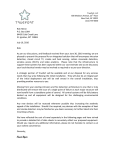
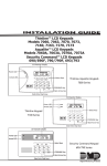
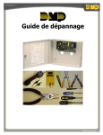
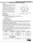
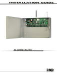
Installation Guide
1101 Universal Transmitter
Description
The 1101 is a two input transmitter that is typically used for door/window applications. The 1101 provides two
internal magnetic reed switches and an on-board terminal block to allow for external contact wiring. Both sets
of contacts, internal and external, can be programmed to operate at the same time allowing for two independent
zones from one transmitter. Refer to the panel programming guide for zone programming information.
Using the on-board LED the 1101 Universal Transmitter provides built-in survey capability to allow for single-person
installations, eliminating the requirement for an external survey kit. A transmitter mounting bracket is included to
make the installation quick and easy. For added security, an internal case tamper switch is provided.
The 1101 Transmitter operates with the XR500 Series Command Processor™ panels or XR100 Series Command
Processor™ panels using the 1100X Receiver or with the XRSuper6, XR20, and XR40 Command Processor™ panels using
the 1100D Receiver.
What is Included
The 1101 Universal Transmitter includes the following
items:
• One 1101 Transmitter PCB mounted in a two-part
housing (base and cover)
• One Magnet housing and base
• One 3V lithium CR123A Battery
• Hardware pack
• Zone name and number label
• Serial number label
• Optional Transmitter mounting bracket
• Optional magnet mounting spacer
• Optional double-sided tape
Transmitter Serial Number
1101 Universal
Transmitter
Squeeze External
Case Ends together to
Remove Cover
Ensure there is 5/8" or less
betweentheassembledMagnet
HousingandTransmitterHousing.
Squeeze External
Case Ends together
to Remove Cover
Magnet
Housing
Figure 1: Mounted Transmitter and Magnet
For your convenience, an additional pre-printed serial number label is included. Prior to installing the device,
record the serial number or place the pre-printed serial number label on the panel programming sheet. This number
is required during programming. As needed, use the zone name and number label to identify a specific transmitter.
Programming the Transmitter in the Panel
Refer to the XR500 Series Programming Guide (LT-0679), XR100 Series Programming Guide (LT-0896), or the
XRSuper6/XR20/XR40 Programming Guide (LT-0305) as needed. Program the device as a zone in Zone Information
during panel programming. At the Serial Number: prompt, enter the eight-digit serial number, including leading
zeros. Continue to program the zone as directed in the panel programming guide.
Note: When a receiver is installed, powered up, or the panel is reset, the supervision time for transmitters is reset.
If the receiver has been powered down for more than one hour, wireless transmitters may take up to an additional
hour to send a supervision message unless tripped, tampered, or powered up. This operation extends battery life for
transmitters. A missing message may display on the keypad until the transmitter sends a supervision message.
Selecting the Proper Location (LED Survey Operation)
The 1101 Transmitter provides a survey capability to allow one person to confirm transmitter communication with
the receiver while the cover is removed. The 1101 Transmitter PCB Red Survey LED turns on whenever data is
sent to the receiver then immediately turns off when the receiver acknowledgement is received. Pressing the
tamper switch is a convenient way to send data to the receiver to confirm operation. When the tamper switch
is pressed or released, the LED blinks once to indicate proper operation. When the transmitter does not receive
an acknowledgement from the receiver the LED remains on for about 8 seconds to let you know communication is
not established. Communication is also faulty when the LED flashes multiple times in quick succession. Relocate
the transmitter or receiver until the LED immediately turns off indicating the transmitter and receiver are
communicating properly. Proper communication between the transmitter and receiver is verified when for each
press or release of the tamper switch, the LED blinks immediately on and immediately off. Repeat this test to
confirm five separate consecutive LED blinks. Any indication otherwise means proper communication has not been
established.
www.BevanSecurity.Com
Mounting the Transmitter and Magnet Assemblies
For internal contact operation, the transmitter and magnet assembly should have no more than 5/8" space between
the assembled housings after installation. When mounting on metal (ferrous) surfaces, this distance is slightly less.
For door installations, it is recommended the transmitter be mounted on the door frame and the magnet assembly
be mounted on the door.
Magnet Housing and Base
Only one magnet assembly is required for internal reed switch operation. Depending
on the installation, you can use either the end mount internal reed switch or side
mount internal reed switch location of the transmitter. For reference, both mounting
locations and other mounting information is included in Figures 3 and 4. An optional
magnet housing spacer is provided for installations where the magnet assembly needs
to be raised in order to line up with the reed switches in the transmitter.
Magnet
Housing
Magnet
Housing
Base
#6 Flat Head
Mounting
Screws
Installing the Optional Mounting Bracket
The following instructions cover installing the transmitter using the mounting bracket.
Optional
Housing Spacer
If the installation does not require the mounting bracket, refer to Installing the
Figure 2: Magnet Assembly
Transmitter without the Mounting Bracket. 1.Secure the mounting bracket using the supplied screws or double-sided tape. Make sure the reed switch
location markers are positioned where you plan to mount and install the magnet housing.
2.Place the magnet housing base on the surface nearest to one of the internal reed switch locations and use the
provided screws or double-sided tape to secure the magnet mounting base. If needed, set the mounting spacer
below the housing base and align the mounting holes together.
Note: The magnet housing base must be located a minimum of 1/8" from the alignment bracket. The 1/8"
distance is required to ensure the magnet housing and transmitter housing have enough space between them
when mounted. When using the magnet spacer, place the spacer next to the alignment bracket. No additional
space is required between the spacer and the bracket. See Figure 3 Section B.
3.Snap the magnet housing onto the housing base.
4.Line the transmitter base up with the mounting bracket snap connectors and press the transmitter into place.
5.Spring must be in place on tamper switch for normal operation.
Alignment Bracket
(BreakoffforOperation)
Minimum1/8"
MountingDistance
Reed Switch
Alignment Arrows
MagnetHousing
Base Notch
Snap Connectors
for Transmitter
Installation
Minimum1/8"
MountingDistance
A. Optional Mounting Bracket and Magnet
Mounting
Bracket
Mounting
Bracket
WallMount
ScrewHoles
MagnetHousing
Spacer
B. Optional Magnet Housing Spacer
Figure 3: Optional Mounting Bracket and Magnet Base and Spacer Mounting
Side
Mount
Magnet
Transmitter
End
Mount
Magnet
Figure 4: View of Side and End Mount Magnets
Note: For UL listed installations, do not use the optional mounting bracket. See Installing the Transmitter without
the Mounting Bracket on the next page.
Digital Monitoring Products
2
www.BevanSecurity.Com
1101 Installation Guide
Installing the Transmitter without the Mounting Bracket
These instructions cover installing the transmitter using the base housing without the mounting bracket. If the
installation requires the mounting bracket, refer to Installing the Optional Mounting Bracket above. 1.Remove the battery if installed.
2.Hold the transmitter base in place with the reed switch nearest to the area where you plan to mount the
magnet.
3.Place one supplied screw into the mounting hole location as shown in Figure 5 or use double-sided tape and
secure the housing to the surface.
4.Place the magnet housing base on the surface nearest to one of the internal reed switch locations and use the
provided screws or double-sided tape to secure the magnet mounting base in place. See Figure 2.
5.If needed, place the magnet mounting spacer below the magnet housing base, align the holes, and use the
provided screws or double-sided tape to secure the base and spacer in place.
U4
Y2
Antenna
J2
J4 Terminal
Block
Tamper
Switch
S1
Transmitter Base
Internal and External Contact Mounting
When connecting an external contact to the terminal
block, DMP recommends using 18 or 22-gauge unshielded
wire. Do not use twisted pair or shielded wire.
Connect the external contact as normally open (N/O) or
normally closed (N/C) without any end-of-line resistor.
Refer to the Contact option under Zone Information
in the XR500 Series Programming Guide (LT-0679),
the XR100 Series Programming Guide (LT-0896) or the
XRSuper6/XR20/XR40 Programming Guide (LT-0305). R14 Reed Switch
Transmitter PCB
R7 Reed Switch
D1 LED and Lens
J1
Antenna
Mounting
Block
6. Spring must be in place on tamper switch for normal
operation.
InternalContactMagneticReed Switches
Red LED (Survey)
MountingHole
Battery
Mounting
Location
External Contact Terminal Block
Figure 5: Internal and External Contact Points
External Contact
Terminal Block
1101 Universal
Transmitter
S1 r
pe
Tam itch
Sw
External
Contact
inal
Term k
Bloc
J1 a
tenn
An nting
Mou ock
Bl
Note: When using both contacts, you
must use consecutive zone numbers.
Refer to the following examples:
• XR500 system — zones 562 and 563
or zones 893 and 894
• XR100 system — zones 523 and 524
or zones 593 and 594
• XRSuper6, XR20, or XR40 system —
zones 31 and 32 or zones 34 and 41
J4
U4
ery
tt
Ba ting
un
n
Mo
tio
ca
Lo
Y2
h
J2
itc
Sw
ed
Re
R7
a
ed
4 Re
tenn
An
er
itt
sm
n
Tra
Sw
B
PC
d Le
ns
D an
D1
LE
Magnet
h
itc
R1
Internal Contact
Reed Switches
Internal Contact
Door
1101
Transmitter
Program External
Contact as next
consecutive Zone
Magnet
External Contact
Program Internal
Contact as one Zone
Magnet
Window
Figure 6: External Contact Wiring
Note: For UL listed installations, program
the external contact as Normally Closed (N/C). See Zone Programming in the XR500 Series Programming Guide
(LT‑0679), the XR100 Series Programming Guide (LT-0896) or the XRSuper6, XR20, XR40 Programming Guide (LT-0305).
Installing or Replacing the Battery
Observe polarity when installing the battery. Use only 3.0V lithium batteries, DMP Model CR123, or the equivalent
battery from a local retail outlet. For UL installations, only use CR123A batteries manufactured by Tekcell.
Note: When setting up a wireless system, it is recommended to program zones and connect the receiver before
installing batteries in the transmitters.
1.If installed, remove the transmitter housing cover.
2.If replacing the battery, remove the old battery and dispose of it properly.
3.Place the 3.0V lithium battery in the holder as shown in Figure 5 and press into place.
4.Line the transmitter cover so the DMP logo is over the battery and snap the cover back into place.
Caution: Risk of fire, explosion, and burns. Do not recharge, disassemble, heat above 212°F (100°C), or
incinerate. Properly dispose of unused batteries.
1101 Installation Guide
www.BevanSecurity.Com
Digital Monitoring Products
3
Battery Life Expectancy
Typical battery life expectancy for DMP Model 1101 wireless transmitters is 5 years. DMP wireless equipment uses
two-way communication to extend battery life.
The following situations can reduce battery life expectancy:
• If a receiver is unplugged or not installed. Note: Transmitters continue to send supervision messages until a receiver returns an acknowledgement.
After an hour the transmitter only attempts a supervision message every 60 minutes.
• Frequent transmissions, such as a door contact where messages are sent every time the door opens or closes.
• When installed in extreme hot or cold environments.
The following situation can extend battery life expectancy:
• Extend transmitter supervision time in panel programming.
• Infrequent transmission trips, such as a window that rarely sends messages.
FCC Information
This device complies with Part 15 of the FCC Rules. Operation is subject to the following two conditions:
(1) This device may not cause harmful interference, and
(2) this device must accept any interference received, including interference that may cause undesired operation.
The antenna used for this transmitter must be installed to provide a separation distance of at least 20 cm from all
persons. It must not be co-located or operated in conjunction with any other antenna or transmitter.
Changes or modifications made by the user and not expressly approved by the party responsible for compliance could
void the user’s authority to operate the equipment.
Patents
Battery
Life Expectancy 5 years (normal operation)
Type
3.0V lithium CR123A
See Battery Life Expectancy for full details.
Frequency Range: 903-927 MHz
Dimensions
Transmitter Case 3.3” L x 1.6” W x 1.2” H
Transmitter Base 2.5” L x 1.3” W x 0.1” H
Magnet Housing 1.5” L x 0.5” W x 0.7” H
Magnet Spacer
1.5” L x 0.5” W x 0.1” H
Color
White
Housing Material
Flame retardant ABS
800-641-4282
Patent(s) Pending
Listings and Approvals
FCC Part 15 Registration ID CCK1101
IC Registration ID 5251A-PC0081
Underwriters Laboratories (UL) Listed
ANSI/UL 1023 Household Burglar Alarm System Units Accessory Magnetically Activated Switch or Door
Contact Transmitter
ANSI/UL 634 Connections and Switches for use with Burglar Alarm Systems Accessory
ANSI/UL 985 Household Fire Warning System Accessory
INTRUSION • FIRE • ACCESS • NETWORKS
www.dmp.com
2500 North Partnership Boulevard
Made in the USA
Springfield, Missouri 65803-8877
www.BevanSecurity.Com
8303
Specifications
LT-0694 11.06 © 2008 Digital Monitoring Products, Inc.
NOTE: This equipment has been tested and found to comply with the limits for a Class B digital device, pursuant
to part 15 of the FCC Rules. These limits are designed to provide reasonable protection against harmful
interference in a residential installation. This equipment generates, uses and can radiate radio frequency
energy and, if not installed and used in accordance with the instructions, may cause harmful interference
to radio communications. However, there is no guarantee that interference will not occur in a particular
installation. If this equipment does cause harmful interference to radio or television reception, which
can be determined by turning the equipment off and on, the user is encouraged to try to correct the
interference by one or more of the following measures:
- Reorient or relocate the receiving antenna.
- Increase the separation between the equipment and receiver.
- Connect the equipment into an outlet on a circuit different from that to which the receiver is connected.
- Consult the dealer or an experienced radio/TV technician for help.