1
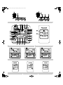
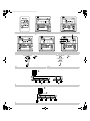
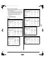
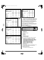
00_CV_3P215731-1D.fm Page 1 Wednesday, February 6, 2008 11:34 AM
OPERATION MANUAL
System air conditioner
MODEL
RXYQ72PYDN
RXYQ96PYDN
RXYQ120PYDN
RXYQ144PYDN
RXYQ168PYDN
RXYQ192PYDN
RXYQ216PYDN
RXYQ240PYDN
RXYQ72PTJU
RXYQ96PTJU
RXYQ120PTJU
RXYQ144PTJU
RXYQ168PTJU
RXYQ192PTJU
RXYQ216PTJU
RXYQ240PTJU
English
REYQ72PYDN
REYQ96PYDN
REYQ120PYDN
REYQ144PYDN
REYQ168PYDN
REYQ192PYDN
REYQ216PYDN
REYQ240PYDN
REYQ72PTJU
REYQ96PTJU
REYQ120PTJU
REYQ144PTJU
REYQ168PTJU
REYQ192PTJU
REYQ216PTJU
REYQ240PTJU
Read these instructions carefully before installation.
Keep this manual in a handy place for future reference.
This manual should be left with the equipment owner.
Français
Español
00_CV_3P215731-1D.fm Page 2 Wednesday, February 6, 2008 11:34 AM
1
RXYQ
REYQ
F
2
3
F
F
4
5
6
7-1
7-2
7-3
00_CV_3P215731-1D.fm Page 3 Wednesday, February 6, 2008 11:34 AM
F
8
9
F
10
11
Double-flow Multi-flow
13-1
14
15
F
12
Corner
Double-flow Multi-flow
Ceiling Suspended
Ceiling Suspended
Wall Mounted
Wall Mounted
13-2
Corner
01_EN_3P215731-1D.fm Page 1 Tuesday, February 5, 2008 6:35 PM
RXYQ72PYDN
RXYQ96PYDN
RXYQ120PYDN
RXYQ144PYDN
RXYQ168PYDN
RXYQ192PYDN
RXYQ216PYDN
RXYQ240PYDN
REYQ72PYDN
REYQ96PYDN
REYQ120PYDN
REYQ144PYDN
REYQ168PYDN
REYQ192PYDN
REYQ216PYDN
REYQ240PYDN
RXYQ72PTJU
RXYQ96PTJU
RXYQ120PTJU
RXYQ144PTJU
RXYQ168PTJU
RXYQ192PTJU
CONTENTS
1. SAFETY CONSIDERATIONS ......................... 1
2. SPECIFICATIONS .......................................... 4
3. WHAT TO DO BEFORE OPERATION............ 5
4. REMOTE CONTROLLER AND COOL/HEAT
SELECTOR : NAME AND FUNCTION OF
EACH SWITCH AND DISPLAY ...................... 5
5. OPERATION RANGE ..................................... 7
6. OPERATION PROCEDURE ........................... 7
7. OPTIMUM OPERATION ............................... 11
8. SEASONAL MAINTENANCE ....................... 12
9. FOLLOWING SYMPTOMS ARE NOT AIR
CONDITIONER TROUBLES ........................ 12
10. TROUBLE SHOOTING................................. 14
1. SAFETY CONSIDERATIONS
Please read these “SAFETY CONSIDERATIONS”
carefully before installing the air conditioning unit
and be sure to install it correctly. After completing
the installation, make sure that the unit operates
properly during the test operation.
Please instruct the customer on how to operate the
unit and keep it maintained.
Also, inform the customer that this operation manual
should be stored along with the installation manual
for future reference.
This air conditioner comes under the term “appliances not accessible to the general public”.
Meaning of danger, warning, caution and note symbols.
DANGER ......... Indicates an imminently hazardous situation which, if not
avoided, will result in death or
serious injury.
WARNING ....... Indicates a potentially hazardous situation which, if not
avoided, could result in death
or serious injury.
CAUTION ......... Indicates a potentially hazardous
situation which, if not avoided,
may result in minor or moderate
injury. It may also be sued to alert
against unsafe practices.
1
RXYQ216PTJU
RXYQ240PTJU
REYQ72PTJU
REYQ96PTJU
REYQ120PTJU
REYQ144PTJU
REYQ168PTJU
REYQ192PTJU
REYQ216PTJU
REYQ240PTJU
VRVIII System
air conditioner
Operation
manual
NOTE .............. Indicates a situation that may
result in the unit or propertydamage-only accidents.
Keep these warning sheets handy so that you
can refer to them if needed.
Also, if this unit is transferred to a new user, make sure
to hand over this operation manual to the new user.
DANGER
• Refrigerant gas may produce a toxic gas if it
comes in contact with fire such as from a fan,
heater, stove or cooking device. Exposure to
this gas could cause severe injury or death.
• For refrigerant leakage, consult your dealer.
Refrigerant gas is heavier than air and replaces oxygen. A massive leak could lead to oxygen depletion,
especially in basements, and an asphyxiation hazard could occur leading to serious injury or death.
• Any abnormalities in the operation of the air
conditioner such as smoke or fire could result
in severe injury or death.
Turn off the power and contact your dealer immediately for instructions.
• Do not install the unit in an area where flammable materials are present due to risk of
explosion resulting in serious injury or death.
• If equipment utilizing a burner is used in the
same room as the air conditioner, there is the
danger of oxygen deficiency which could lead
to an asphyxiation hazard resulting in serious
injury or death.
Be sure to ventilate the room sufficiently to avoid
this hazard.
• Safely dispose of the packing materials.
Packing materials, such as nails and other metal or
wooden parts, may cause stabs or other injuries.
Tear apart and throw away plastic packaging bags
so that children will not play with them. Children
playing with plastic bags face the danger of death
by suffocation.
WARNING
• Be sure to install a ground fault circuit breaker.
Failure to install a ground fault circuit interrupter
may result in electric shocks or fire.
• It is not good for your health to expose your
body to the air flow for a long time.
English
01_EN_3P215731-1D.fm Page 2 Tuesday, February 5, 2008 6:35 PM
• Ask your dealer to install in a machine room
that has no water drops by raining. This unit is
for indoor use.
Incomplete installation performed by yourself may
result in a water leakage, electric shock, and fire.
• Ask your dealer for improvement, repair, and
maintenance.
Incomplete improvement, repair, and maintenance
may result in a water leakage, electric shock, and fire.
• Improper installation or attachment of equipment or accessories could result in electric
shock, short-circuit, leaks, fire or other damage to the equipment. Be sure only to use
accessories made by Daikin which are specifically designed for use with the equipment
and have them installed by a professional.
• Ask your dealer to move and reinstall the air
conditioner.
Incomplete installation may result in a water leakage, electric shock, and fire.
• Never let the indoor unit or the remote controller get wet.
It may cause an electric shock or a fire.
• Never use flammable spray such as hair spray,
lacquer or paint near the unit.
It may cause a fire.
• Never replace a fuse with that of wrong ampere
ratings or other wires when a fuse blows out.
Use of wire or copper wire may cause the unit to
break down or cause a fire.
• Never remove the fan guard of the unit.
A fan rotating at high speed without the fan guard
is very dangerous.
• Never inspect or service the unit by yourself.
Ask a qualified service person to perform this work.
• Cut off all electric waves before maintenance.
• To avoid the risk of serious electric shock, never
sprinkle or spill water or liquids on the unit.
• Do not touch the switch with wet fingers.
Touching a switch with wet fingers can cause
electric shock.
• Do not allow children to play on or around the
unit as they could be injured.
• The heat exchanger fins are sharp enough to cut.
To avoid injury wear gloves or cover the fins while
working around them.
• Do not put a finger or other objects into the air
inlet or air outlet. The fan is rotating at high
speed and will cause injury.
• Operating the air conditioner with wet hands
could result in a shock hazard.
English
• Check the unit stand for damage on a continuous basis, especially if it has been in use for
a long time.
If left in a damaged condition the unit may fall and
cause injury.
• Placing a flower vase or other containers with
water or other liquids on the unit could result
in a shock hazard or fire if a spill occurs.
• Do not touch the air outlet or horizontal blades
while the swing flap is in operation because
fingers could get caught and injured.
• Be sure to establish an earth.
Do not earth the unit to a utility pipe, arrester, or
telephone earth.
Incomplete earth may cause electrical shock, or fire.
A high surge current from lightning or other
sources may cause damage to the air conditioner.
• Never touch the internal parts of the controller.
Do not remove the front panel because some parts
inside are dangerous to touch. In addition, some
parts may be damaged to touching. For checking
and adjusting internal parts, contact your dealer.
•
•
•
•
•
•
•
CAUTION
Do not use the air conditioner for other purposes.
In order to avoid any quality deterioration, do not
use the unit for cooling precision instruments,
food, plants, animals or works of art.
Do not place items under the indoor unit
which may be damaged by water.
Condensation may form if the humidity is above
80% or if the drain outlet gets blocked.
Before cleaning, be sure to stop the operation,
turn the breaker off or pull out the supply cord.
Otherwise, an electric shock and injury may result.
Never expose little children, plants or animals
directly to the air flow.
Adverse influence to little children, animals and
plants may result.
Do not wash the air conditioner with excessive water.
An electric shock or fire may result.
Avoid placing the controller in a spot splashed
with water.
Water coming inside the controller may cause an
electric leak or may damage the internal electronic parts.
Do not operate the air conditioner when using
a room fumigation - type insecticide.
Failure to observe could cause the chemicals to
become deposited in the unit, which could endanger the
health of those who are hypersensitive to chemicals.
2
01_EN_3P215731-1D.fm Page 3 Tuesday, February 5, 2008 6:35 PM
• Do not turn off the power immediately after
stopping operation.
Always wait at least five minutes before turning off
the power. Otherwise, water leakage and trouble
may occur.
• The appliance is not intended for use by young
children or infirm persons without supervision.
• The remote controller should be installed in
such away that children cannot play with it.
• Consult with installation contractor for cleaning the inside of the air conditioner.
Wrong cleaning may make the plastics parts broken
or cause failure of water leakage or electric shock.
• Do not touch the air inlet or aluminum fin of
the air conditioner.
Otherwise, injury may be caused.
• Do not place objects in direct proximity of the
outside unit and do not let leaves and other
debris accumulate around the unit.
Leaves are a hotbed for small animals which can
enter the unit. Once in the unit, such animals can
cause malfunctions, smoke or fire when making
contact with electrical parts.
•
•
•
•
•
•
•
3
NOTE
Never press the button of the remote controller with a hard, pointed object.
The remote controller may be damaged.
Never pull or twist the electric wire of the
remote controller.
It may cause the unit to malfunction.
Do not place appliances which produce open
fire in places exposed to the air flow from the
unit or under the indoor unit. It may cause
incomplete combustion or deformation of the
unit due to the heat.
Arrange the drain hose to ensure smooth
drainage. Incomplete drainage may cause
wetting of the building, furniture etc.
Do not place the controller exposed to direct
sunlight.
The LCD display may get discolored, failing to display the data.
Do not wipe the controller operation panel
with benzine, thinner, chemical dustcloth, etc.
The panel may get discolored or the coating peeled
off. If it is heavily dirty, soak a cloth in water-diluted
neutral detergent, squeeze it well and wipe the
panel clean. And wipe it with another dry cloth.
Dismantling of the unit, treatment of the refrigerant, oil and eventual other parts, should be
done in accordance with the relevant local and
national regulations.
[Place of Installation]
• Make sure that the air conditioner is located in
a sufficiently ventilated place not surrounded
by obstacles.
• Do not use the air conditioner in the following
places.
a. Places with a mist of mineral oil, such as cutting oil.
b. Locations such as coastal areas where there is
a lot of salt in the air.
c. Locations such as hot springs resorts where
there is a lot of sulfur in the air.
d. Locations such as factories where the power
voltage varies a lot.
e. In cars, boats, and other vehicles.
f. Locations such as kitchens where oil may splatter or there is steam in the air.
g. Locations where equipment that produces electromagnetic waves is found.
h. Places with an acid or alkaline mist.
i. Places where fallen leaves are accumulated or
weeds grow close together.
• Take snow protection measures.
Contact your dealer for the details of snow protection measures, such as the use of a snow protection hood.
[Electrical Work]
• Do not attempt to conduct electrical work or
grounding work unless you are licensed to do so.
Consult with your dealer for electrical work and
grounding work.
• Use a dedicated circuit for the air conditioner.
[Pay Attention to Operating Sound]
• Be sure to use the following places.
a. Places that can sufficiently withstand the weight
of the air conditioner and suppress the operating sound and vibration of the air conditioner.
b. Places where warm air from the air outlet of the
outside unit or the operating sound of the outside unit does not annoy neighbors.
• Make sure that there are no obstacles close to
the outside unit.
Obstacles close to the outside unit may drop the
performance of the outside unit or an increase in
the operating sound of the outside unit.
• Consult your dealer if the air conditioner in
operation generates unusual noise.
English
01_EN_3P215731-1D.fm Page 4 Tuesday, February 5, 2008 6:35 PM
[Drainage through Drainpipe]
• Make sure that the drainpipe is installed properly to drain water.
If no water is discharged from the drainpipe while
the air conditioner is cooling operation, the drainpipe may be clogged with dust or dirt and water
leakage from the indoor units may result.
Stop operating the air conditioner and consult
your dealer.
2. SPECIFICATIONS
[RXYQ]
RXYQ72PYDN
Model name
Power supply
Phase
—
3~
Frequency
(Hz)
60
Voltage
(V)
460
72
Nominal cooling capacity (MBh)
81
Nominal heating capacity (MBh)
66-1/8×
(inch) 36-5/8×30-1/8
Dimensions H×W×D
(Ib)
573
Mass
Refrigerant
type
—
R410A
charge (*1)
(Ib)
18.1
Design pressure
High side
(psig)
478
Low side
(psig)
320
RXYQ96PYDN RXYQ120PYDN
3~
60
460
96
108
66-1/8×
36-5/8×30-1/8
573
3~
60
460
120
135
66-1/8×
36-5/8×30-1/8
573
R410A
19.8
R410A
20.1
478
320
478
320
RXYQ144PYDN RXYQ168PYDN RXYQ192PYDN
Model name
Power supply
Phase
—
3~
3~
3~
Frequency
(Hz)
60
60
60
Voltage
(V)
460
460
460
144
168
192
Nominal cooling capacity (MBh)
162
189
216
Nominal heating capacity (MBh)
(66-1/8×36-5/
(66-1/8×36-5/
(66-1/8×36-5/
8×30-1/8)+
8×30-1/8)+
8×30-1/8)+
(66-1/8×36-5/
(66-1/8×36-5/
(inch) (66-1/8×36-5/
Dimensions H×W×D
8×30-1/8)
8×30-1/8)
8×30-1/8)
(Ib)
573+573
573+573
573+573
Mass
Refrigerant
type
—
R410A
R410A
R410A
charge (*1)
(Ib)
18.1+18.1
18.1+19.8
18.1+20.1
Design pressure
High side
(psig)
478
478
478
Low side
(psig)
320
320
320
RXYQ216PYDN RXYQ240PYDN
Model name
Power supply
Phase
—
3~
3~
Frequency
(Hz)
60
60
Voltage
(V)
460
460
216
240
Nominal cooling capacity (MBh)
243
270
Nominal heating capacity (MBh)
(66-1/8×36-5/
(66-1/8×36-5/
8×30-1/8)+
8×30-1/8)+
(66-1/8×36-5/
(inch) (66-1/8×36-5/
Dimensions H×W×D
8×30-1/8)
8×30-1/8)
(Ib)
573+573
573+573
Mass
Refrigerant
type
—
R410A
R410A
charge (*1)
(Ib)
19.8+20.1
20.1+20.1
Design pressure
High side
(psig)
478
478
Low side
(psig)
320
320
English
RXYQ72PTJU RXYQ96PTJU RXYQ120PTJU
Model name
Power supply
Phase
—
3~
3~
3~
Frequency
(Hz)
60
60
60
Voltage
(V)
208-230
208-230
208-230
72
96
120
Nominal cooling capacity (MBh)
81
108
135
Nominal heating capacity (MBh)
66-1/8×36-5/8× 66-1/8×36-5/8×
(inch) 66-1/8×36-5/8×
Dimensions H×W×D
30-1/8
30-1/8
30-1/8
(Ib)
560
560
560
Mass
Refrigerant
type
—
R410A
R410A
R410A
charge (*1)
(Ib)
18.1
19.8
20.1
Design pressure
High side
(psig)
478
478
478
Low side
(psig)
320
320
320
RXYQ144PTJU RXYQ168PTJU RXYQ192PTJU
Model name
Power supply
Phase
—
3~
3~
3~
Frequency
(Hz)
60
60
60
Voltage
(V)
208-230
208-230
208-230
144
168
192
Nominal cooling capacity (MBh)
162
189
216
Nominal heating capacity (MBh)
(66-1/8×36-5/8× (66-1/8×36-5/8×
66-1/8×
30-1/8)+
30-1/8)+
(inch)
51-3/16×
Dimensions H×W×D
(66-1/8×36-5/8× (66-1/8×36-5/8×
30-1/8
30-1/8)
30-1/8)
(Ib)
747
560+560
560+560
Mass
Refrigerant
type
—
R410A
R410A
R410A
charge (*1)
(Ib)
24.5
18.1+19.8
18.1+20.1
Design pressure
High side
(psig)
478
478
478
Low side
(psig)
320
320
320
RXYQ216PTJU RXYQ240PTJU
Model name
Power supply
Phase
—
3~
3~
Frequency
(Hz)
60
60
Voltage
(V)
208-230
208-230
216
240
Nominal cooling capacity (MBh)
243
270
Nominal heating capacity (MBh)
(66-1/8×36-5/8× (66-1/8×36-5/8×
30-1/8)+
30-1/8)+
(inch) (66-1/8×36-5/8×
Dimensions H×W×D
(66-1/8×36-5/8×
30-1/8)
30-1/8)
(Ib)
560+560
560+560
Mass
Refrigerant
type
—
R410A
R410A
charge (*1)
(Ib)
19.8+20.1
20.1+20.1
Design pressure
High side
(psig)
478
478
Low side
(psig)
320
320
[REYQ]
REYQ72PYDN
Model name
Power supply
Phase
—
3~
Frequency
(Hz)
60
Voltage
(V)
460
72
Nominal cooling capacity (MBh)
81
Nominal heating capacity (MBh)
66-1/8×
(inch) 51-1/4×30-1/8
Dimensions H×W×D
(Ib)
732
Mass
Refrigerant
type
—
R410A
charge (*1)
(Ib)
22.7
Design pressure
High side
(psig)
478
Low side
(psig)
320
REYQ96PYDN REYQ120PYDN
3~
60
460
96
108
66-1/8×
51-1/4×30-1/8
732
3~
60
460
120
135
66-1/8×
51-1/4×30-1/8
732
R410A
23.4
R410A
23.8
478
320
478
320
4
01_EN_3P215731-1D.fm Page 5 Tuesday, February 5, 2008 6:35 PM
REYQ144PYDN REYQ168PYDN REYQ192PYDN
Model name
Power supply
Phase
—
3~
3~
3~
Frequency
(Hz)
60
60
60
Voltage
(V)
460
460
460
144
168
192
Nominal cooling capacity (MBh)
162
189
216
Nominal heating capacity (MBh)
(66-1/8×36-5/
(66-1/8×36-5/
(66-1/8×36-5/
8×30-1/8)+
8×30-1/8)+
8×30-1/8)+
(66-1/8×36-5/
(66-1/8×36-5/
(inch) (66-1/8×36-5/
Dimensions H×W×D
8×30-1/8)
8×30-1/8)
8×30-1/8)
(Ib)
463+463
463+573
463+573
Mass
Refrigerant
type
—
R410A
R410A
R410A
charge (*1)
(Ib)
18.1+18.1
18.1+19.8
19.8+19.8
Design pressure
High side
(psig)
478
478
478
Low side
(psig)
320
320
320
*1: Refrigerant charge at factory shipment
REYQ216PYDN REYQ240PYDN
Model name
Power supply
Phase
—
3~
3~
Frequency
(Hz)
60
60
Voltage
(V)
460
460
216
240
Nominal cooling capacity (MBh)
243
270
Nominal heating capacity (MBh)
(66-1/8×36-5/
(66-1/8×36-5/
8×30-1/8)+
8×30-1/8)+
(66-1/8×36-5/
(inch) (66-1/8×36-5/
Dimensions H×W×D
8×30-1/8)
8×30-1/8)
(Ib)
573+573
573+573
Mass
Refrigerant
type
—
R410A
R410A
charge (*1)
(Ib)
18.1+20.1
20.1+20.1
Design pressure
High side
(psig)
478
478
Low side
(psig)
320
320
REYQ72PTJU
Model name
Power supply
Phase
—
3~
Frequency
(Hz)
60
Voltage
(V)
208-230
72
Nominal cooling capacity (MBh)
81
Nominal heating capacity (MBh)
66-1/8×
(inch)
51-3/16×
Dimensions H×W×D
30-1/8
(Ib)
730
Mass
Refrigerant
type
—
R410A
charge (*1)
(Ib)
22.7
Design pressure
High side
(psig)
478
Low side
(psig)
320
REYQ96PTJU
REYQ216PTJU REYQ240PTJU
Model name
Power supply
Phase
—
3~
3~
Frequency
(Hz)
60
60
Voltage
(V)
208-230
208-230
216
240
Nominal cooling capacity (MBh)
243
270
Nominal heating capacity (MBh)
(66-1/8×36-5/8× (66-1/8×36-5/8×
30-1/8)+
30-1/8)+
(inch) (66-1/8×36-5/8×
Dimensions H×W×D
(66-1/8×36-5/8×
30-1/8)
30-1/8)
(Ib)
560+560
560+560
Mass
Refrigerant
type
—
R410A
R410A
charge (*1)
(Ib)
19.8+20.1
20.1+20.1
Design pressure
High side
(psig)
478
478
Low side
(psig)
320
320
3. WHAT TO DO BEFORE OPERATION
This operation manual is for the following system
with standard control. Before initiating operation,
contact your Daikin dealer for the operation that corresponds to your system type and mark.
If your installation has a customized control system,
ask your Daikin dealer for the operation that corresponds to your system.
Outside units (Refer to figure 1)
COOL/HEAT selector
REYQ120PTJU
Operation modes
Inverter series
3~
60
208-230
96
108
66-1/8×
51-3/16×
30-1/8
730
3~
60
208-230
120
135
66-1/8×
51-3/16×
30-1/8
730
R410A
23.4
R410A
23.8
478
320
478
320
REYQ144PTJU REYQ168PTJU REYQ192PTJU
Model name
Power supply
Phase
—
3~
3~
3~
Frequency
(Hz)
60
60
60
Voltage
(V)
208-230
208-230
208-230
144
168
192
Nominal cooling capacity (MBh)
162
189
216
Nominal heating capacity (MBh)
(66-1/8×36-5/8× (66-1/8×36-5/8×
66-1/8×
30-1/8)+
30-1/8)+
(inch)
51-3/16×
Dimensions H×W×D
(66-1/8×36-5/8× (66-1/8×36-5/8×
30-1/8
30-1/8)
30-1/8)
(Ib)
747
450+560
450+560
Mass
Refrigerant
type
—
R410A
R410A
R410A
charge (*1)
(Ib)
24.5
18.1+19.8
18.1+20.1
Design pressure
High side
(psig)
478
478
478
Low side
(psig)
320
320
320
heat pumps RXYQ series ❏ yes ❏ no
Heat recovery series
heat pumps REYQ series ❏ yes ❏ no
• Names and functions of parts (Refer to figure 1)
1. Outside unit
2. Indoor unit
3. Remote controller
4. Inlet air
5. Outlet air
6. BS unit
7. Cool/Heat selector
8. Refrigerant piping
(figure 1 shows system with Cool/Heat selector)
4. REMOTE CONTROLLER AND
COOL/HEAT SELECTOR : NAME
AND FUNCTION OF EACH
SWITCH AND DISPLAY
(Refer to figure 2 and 3)
1. On/off button
Press the button and the system will start. Press
the button again and the system will stop.
2. Operation lamp (red)
The lamp lights up during operation.
5
English
01_EN_3P215731-1D.fm Page 6 Tuesday, February 5, 2008 6:35 PM
” (changeover under control)
3. Display “
It is impossible to changeover heat/cool with the
remote controller which display this icon.
Refer to the chapter “6-5 SETTING THE MASTER REMOTE CONTROLLER”.
” (air flow flap)
4. Display “
Refer to the chapter “6-3 ADJUSTING THE AIR
FLOW DIRECTION”.
5. Display “
” (ventilation/air cleaning)
This display shows that the ventilation unit are in
operation. (these are optional accessories.)
18. Temperature setting button
Use this button for setting the desired temperature.
Refer to the chapter “6-1 COOLING, HEATING,
AUTOMATIC AND FAN ONLY OPERATION”.
19. Filter sign reset button
Refer to the operation manual of indoor unit.
20. Fan speed control button
Press this button to select the fan speed of your
preference.
”“
”“
”“
”“
”
7. Display “
(operation mode)
This display shows the current operation mode.
21. Operation mode selector button
• Press this button to select the operation mode of
your preference.
• Press this button to designate the master remote
controller.
Refer to the chapter “6-5 SETTING THE MASTER REMOTE CONTROLLER”.
8. Display “ ” (programmed time)
This display shows the programmed time of the
system start or stop.
22. Air flow direction adjust button
Refer to the chapter “6-3 ADJUSTING THE AIR
FLOW DIRECTION”.
9. Display “
TEST ” (inspection/test operation)
When the inspection/test operation button is
pressed, the display shows the mode in which
the system actually is.
23. Fan only/air conditioning selector switch
Set the switch to “
” for fan only operation or to
“
” for heating or cooling operation.
6. Display “
F ” (set temperature)
This display shows the temperature you have set.
10. Display “
” (under centralized control)
When this display shows, the system is under
centralized control. (This is not a standard specification.)
” (fan speed)
11. Display “
This display shows the fan speed you have selected.
” (time to clean air filter)
12. Display “
Refer to the operation manual of indoor unit.
24. Cool/heat changeover switch
” for cooling operation or to
Set the switch to “
“
” for heating operation.
25. Thermistor
It senses the room temperature around the
remote controller.
26. These buttons are used when the ventilation unit
are installed (These are optional accessories.)
Refer to the operation manual of the ventilation unit.
” (defrost/hot start)
13. Display “
Refer to the “EXPLANATION OF HEATING
OPERATION” in chapter 6-1.
•
14. Timer mode start/stop button
Refer to the chapter “6-4 PROGRAMMING START
AND STOP OF THE SYSTEM WITH TIMER”.
•
15. Timer on/off button
Refer to the chapter “6-4 PROGRAMMING START
AND STOP OF THE SYSTEM WITH TIMER”.
16. Inspection/test operation button
This button is only used by qualified service
persons for maintenance purposes.
17. Programming time button
Use this button for setting the programming start
and/or stop time.
Refer to the chapter “6-4 PROGRAMMING START
AND STOP OF THE SYSTEM WITH TIMER”.
English
•
•
•
•
NOTE
Do not place the controller exposed to direct sunlight.
The LCD display may get discolored, failing to display the data.
Never pull or twist the electric wire of a remote
controller.
It may cause the unit to malfunction.
Do not allow sharp or hard items to touch the buttons of the remote controller.
The remote controller may be damaged or breakdown may occur.
Contrary to actual operating situations, the display in figure 2 shows all possible indications.
Figure 2 shows the remote controller with its
cover open.
For FXS, FXM, FXL and FXN, the air flow direction ajust button (22) is not available and the display (4) shows “NOT AVAILABLE” when pressed.
6
01_EN_3P215731-1D.fm Page 7 Tuesday, February 5, 2008 6:35 PM
5. OPERATION RANGE
NOTE
• Automatic operation (REYQ only)
In this operation mode, cool/heat
changeover is automatically conducted.
• The operation mode cannot be changed with
the remote controller whose display shows
“
” (changeover under control).
Change the operation mode with the remote
controller whose display does not show
“
”.
• When the display “
” (changeover
under control) flashes, refer to the chapter
“6-5 SETTING THE MASTER REMOTE
CONTROLLER”.
Use the system in the following temperature and
humidity ranges for safe and effective operation.
COOLING
HEATING
outdoor temperature
23°~110°FDB
0°~60°FWB
indoor temperature
57°~77°FWB
59°~80°FDB
≤ 80%
—
indoor humidity
NOTE
• Cooling operation:
If the air conditioner is operated continuously while
the indoor temperature is 70°F or below and the
humidity is 80% or over, the interiors of the indoor
units may cause icing and water leakage may result.
• Heating operation:
The air conditioner may stop operating for the protection of the machine if the outdoor temperature
is 70°F or over.
6. OPERATION PROCEDURE
• Operation procedure varies according to the combination of outside unit and remote controller.
Read the chapter “What to do before operation”.
• To protect the unit, turn on the main power switch
6 hours before operation.
And do not turn it off during the air conditioning
season for starting operation smoothly.
• If the main power supply is turned off during operation, operation will restart automatically after the
power turns back on again.
6-1 COOLING, HEATING, AUTOMATIC AND
FAN ONLY OPERATION
FOR SYSTEMS WITHOUT COOL/HEAT SELECTOR (Refer to figure 4)
Press the operation mode selector button sev1
eral times and select the operation mode of
your choice;
“
” Cooling operation
“
” Heating operation
“
” Automatic operation
“
” Fan only operation
2
FOR SYSTEMS WITH COOL/HEAT SELECTOR
(Refer to figure 4 and 7)
1
2
Select operation mode with the Cool/Heat
selector as follows:
“ ” “ ” Cooling operation (Refer to figure 7.1)
“ ” “ ” Heating operation (Refer to figure 7.2)
“ ” “ ” Fan only operation (Refer to figure 7.3)
Press the on/off button. (Refer to figure 4)
The operation lamp lights up and the system
starts operation.
ADJUSTMENT (Refer to figure 4)
To adjust the desired temperature, fan speed
and air flow direction (only for the remote controller BRC1A51: FXF, FXH, FXA), follow the
procedure shown below.
3
Press the temperature setting button and set
the desired temperature.
Each time this button is pressed, the temperature setting rises or lowers 1°F.
NOTE
• Set the temperature within the operation
range.
• The temperature setting is impossible for fan
only operation.
4
7
Press the on/off button.
The operation lamp lights up and the system
starts operation.
Press the fan speed control button and select
the fan speed of your preference.
English
01_EN_3P215731-1D.fm Page 8 Tuesday, February 5, 2008 6:35 PM
NOTE
• For machine protection the system may control the air flow rate automatically.
• The air flow rate may be adjusted automatically depending on the room temperature or
the fan may stop immediately. This is not a
malfunction.
• It may take sometime for finishing to change
the air flow rate.
This is normal operation.
5
Press air flow direction adjust button.
Refer to the chapter “6-3 ADJUSTING THE
AIR FLOW DIRECTION” for details.
STOPPING THE SYSTEM (Refer to figure 4)
6
Press the on/off button once again.
The operation lamp goes off and the system
stops operation.
NOTE
• The fan may keep on running for about
1 minute after the heating operation stops
for removing the heat in the indoor unit.
• Do not turn off the power immediately after
the unit stops.
The system need at least 5 minutes for
residual operation of drain pump device.
Turning off the power immediately will cause
water leak or trouble.
EXPLANATION OF HEATING OPERATION
• For general heating operation, it may take longer to
reach the set temperature than in cooling operation.
We recommend starting the operation which was
used before using timer operation.
• The following operation is performed in order to
prevent the heating capacity from dropping or
cold air from blowing.
Defrost operation
• In heating operation, freezing of the outside
unit coil increases. Heating capability
decreases and the system goes into defrost
operation.
• The airflow will be set to breeze or stop.
• If stopped, the display of the remote controller shows “
”.
• Once the airflow is set to breeze or stop, the
air conditioner will return to the previous
state in approximately 5 to 15 minutes.
English
Hot start
• In order to prevent cold air from blowing out
of an indoor unit at the start of heating operation, the indoor fan is automatically
stopped. The display of the remote controller
shows “
”.
• The heating capacity drops as the outside temperature falls. If this happens, use another heating device together with the unit. (When using the
appliances which produce open fire together, ventilate a room constantly.)
Do not place appliances which produce open fire
in places exposed to the air flow from the unit or
under the unit.
• It takes some time for the room to warm up from
the time the unit is started since the unit is a hotair circulatory system to warm the entire room.
• If the hot air rises to the ceiling, leaving the area
above the floor cold, we recommend using the circulator (the indoor fan for circulating air). Contact
your dealer for details.
6-2 PROGRAM DRY OPERATION
• The program dry function deprives the room
of moisture while the air conditioner is in intermittent weak cooling operation so that the
room temperature will not become too low.
• The microcomputer automatically controls
the temperature and fan speed, so these
cannot be set using the remote controller.
• This function is not available if the room temperature is 68°F or lower.
• This function does not controls the humidity.
• FXL and FXN type indoor unit can not operate program dry operation.
FOR SYSTEMS WITHOUT COOL/HEAT SELECTOR (Refer to figure 5)
NOTE
• If “
” (Cooling operation) is not displayed, refer
to “6-1 COOLING, HEATING, AUTOMATIC AND
FAN ONLY OPERATION”, and set “
” (Cooling
operation).
Unless the air conditioner is set to “
” (Cooling
operation), the air conditioner cannot be switched
over to “
” (program dry operation).
8
01_EN_3P215731-1D.fm Page 9 Tuesday, February 5, 2008 6:35 PM
1
2
3
4
Press the operation mode selector button several
times and select “
” (program dry operation).
Press the on/off button.
The operation lamp lights up and the system
starts operation.
6-3 ADJUSTING THE AIR FLOW DIRECTION (Refer to figure 6) (only for Double-flow, Multi-flow, Corner, Ceilingsuspended and Wall-mounted)
1
Press the air flow direction adjust button (only
for FXF, FXH, FXA). Refer to the chapter “6-3
ADJUSTING THE AIR FLOW DIRECTION” for
details.
Press the on/off button once again.
The operation lamp goes off and the system
stops operation.
NOTE
• Do not turn off the power immediately after
the unit stops.
The system need at least 5 minutes for
residual operation of drain pump device.
Turning off the power immediately will cause
water leak or trouble.
2
Press the air flow direction adjust button to select the air direction.
The air flow flap display swings as
shown right and the air flow direction
continuously varies. (Automatic swing
setting)
Press the air flow direction adjust button to
select the air direction of your choice.
The air flow flap display stops swinging and the air flow direction is fixed.
(Fixed air flow direction setting)
MOVEMENT OF THE AIR FLOW FLAP
For the following conditions, a micro computer controls the air flow direction which may be different
from the display.
COOLING
FOR SYSTEMS WITH COOL/HEAT SELECTOR
(Refer to figure 8)
1
2
3
4
5
Select cooling operation mode with the Cool/
Heat selector.
Press the operation mode selector button several times and select program dry “
”.
Press the on/off button.
The operation lamp lights up and the system
starts operation.
Press the air flow direction adjust button (only
for FXF, FXH, FXA). Refer to the chapter “6-3
ADJUSTING THE AIR FLOW DIRECTION” for
details.
Press the on/off button once again.
The operation lamp goes off and the system
stops operation.
NOTE
• Do not turn off the power immediately after
the unit stops.
The system need at least 5 minutes for
residual operation of drain pump device.
Turning off the power immediately will cause
water leak or trouble.
9
HEATING
• When starting operation.
• When the room temperature is
higher than the set temperature.
• At defrost operation.
• When operating continuously at horizontal air flow direction.
• When continuous operation with downward air flow is performed at the time
of cooling with a ceiling-suspended or a wall-mounted unit, the microcomputer may control the flow direction, and then the remote control indication
also will change.
The air flow direction can be adjusted in one of the
following ways.
Automatic “
”: The air flow direction will vary continuously. (Refer to figure 13-1)
Desired position “ ”: The air flow direction can be
fixed by the user.
(Refer to figure 13-2)
NOTE
• The movable limit of the flap is changeable.
Contact your Daikin dealer for details. (Only
for Multi-flow, Ceiling-suspended and Wallmounted.)
• Avoid operating in the horizontal direction
“
”. It may cause dew or dust to settle on
the ceiling.
English
01_EN_3P215731-1D.fm Page 10 Tuesday, February 5, 2008 6:35 PM
6-4 PROGRAMMING START AND STOP OF
THE SYSTEM WITH TIMER
(Refer to figure 9)
• The timer is operated in the following two ways.
Programming the stop time “
”
The system stops operating after the set
time has elapsed.
Programming the start time “
”
The system starts operating after the set
time has elapsed.
• The timer can be programmed for a maximum of 72 hours.
• The start and the stop time can be simultaneously programmed.
1
2
3
Press the timer mode start/stop button several
times and select the mode on the display.
The display flashes.
• For setting the timer stop “
”
• For setting the timer start “
”
Press the programming time button and set
the time for stopping or starting the system.
Each time this button is pressed, the
time advances or goes backward by
1 hour.
Press the timer on/off button.
The timer setting procedure ends. The display
“
” or “
” changes from flashing
light to constant light.
NOTE
• When setting the timer off and on at the
same time, repeat the above procedure
(from “ 1 ” to “ 3 ”) once again.
• After the timer is programmed, the display
shows the remaining time.
• Press the timer on/off button once again to
cancel programming. The display vanishes.
For example: (Refer to figure 11)
When the timer is programmed to stop the system after 3 hours and start the system after 4
hours, the system will stop after 3 hours and
start 1 hour later.
English
6-5 SETTING THE MASTER REMOTE CONTROLLER
• In the case of the system as shown in figure 14,
only the master remote controller can select operation mode.
(Refer to figure 14)
1. Outside unit
2. BS unit
3. Indoor unit
4. Remote controller
5. Some indoor units are connected to one
BS unit.
One of these remote controller is master
remote controller.
6. One indoor unit is connected to one BS unit.
Each remote controller is master remote controller.
In the case of the system as shown in figure 15,
none of the remote controllers can select operation mode.
(Refer to figure 15)
1. Outside unit
2. BS unit
3. Indoor unit
4. Remote controller
5. COOL/HEAT Selector
6. The COOL/HEAT Selector is connected to
BS unit.
The COOL/HEAT Selector can select operation mode.
• Only the master remote controller can select
heating, cooling, automatic operation.
• The displays of slave remote controllers show
“
” (changeover under control) and they
automatically follow the operation mode directed
by the master remote controller.
However, it is possible to changeover to program
dry with slave remote controllers if the system is in
cooling operation by setting on the master remote
controller and to changeover to fan only operation.
• In the case of the system as shown in figure 15,
the display of all remote controllers show
“
” (changeover under control).
10
01_EN_3P215731-1D.fm Page 11 Tuesday, February 5, 2008 6:35 PM
How to designate the master remote controller
(Refer to figure 10)
1
2
Press the operation mode selector button of the
current master remote controller for 4 seconds.
The display showing “
” (changeover
under control) of all remote controllers connected to the same outside unit flashes.
Press the operation mode selector button of
the controller that you wish to designate as the
master remote controller. Then designation is
completed. This remote controller is designated as the master remote controller and the
display showing “
” (changeover
under control) vanishes.
The displays of other remote controllers show
“
” (changeover under control).
How to change the operation mode
(Refer to figure 10)
3
Press the operation mode selection button of
the master remote controller, which does not
show “
” (changeover under control)
repeatedly until the air conditioner is set to the
desired operation mode.
The display will change to FAN, DRY, AUTO
(REYQ models only), COOLING, or HEATING
each time the button is pressed.
The other remote controllers with no option
rights will follow suit and change their displays
automatically.
6-6 PRECAUTIONS FOR GROUP CONTROL SYSTEM OR TWO REMOTE
CONTROLLER CONTROL SYSTEM
This system provides two other control systems
beside individual control (one remote controller controls one indoor unit) system. Confirm which type of
your unit is the following system.
• Group control system
One remote controller controls up to 16 indoor
units. All indoor units are equally set.
• Two remote controller control system
Two remote controllers control one indoor unit (in
case of group control system, one group of indoor
units). The unit is individually operated.
NOTE
• Contact your Daikin dealer in case of changing the combination or setting of group control
and two remote controller control systems.
11
7. OPTIMUM OPERATION
Observe the following precautions to ensure the
system operates properly.
• Prevent direct sunlight from entering a room during cooling operation by using curtains or blinds.
• Do not leave doors and windows open. If the
doors and windows remain open, air will flow out
of your room causing a decrease in the cooling or
heating effect.
• Do not use other heating devices directly beneath
the indoor unit.
If you do, they might get deformed by the heat.
• Never place objects near the air inlet or the air
outlet of the unit. It may cause deterioration in the
effect or stop the operation.
• Adjust the room temperature properly for a comfortable environment. Avoid excessive heating or
cooling.
• Ventilate often.
Extended use requires special attention to ventilation.
• When the display shows “
” (time to clean the
air filter), ask a qualified service person to clean
the filters. (Refer to the chapter “Maintenance” in
the indoor unit manual.)
• Keep the indoor unit and remote controller at least
3.5ft. away from televisions, radios, stereos, and
other similar equipment.
Failing to do so may cause static or distorted pictures.
• Turn off the main power supply switch to the unit
when the unit is not used for longer periods of
time. If the switch is on, it uses electricity. Before
restarting the unit, turn on the main power supply
switch 6 hours before operation to ensure smooth
running. (Refer to the chapter “Maintenance” in
the indoor unit manual.)
• Fully use the function of air flow direction adjust.
Cold air gathers on the floor, and warm air gathers
in the ceiling.
Set the air flow direction parallel during cooling or
dry operation, and set it downwards during heating operation.
Do not let the air blow directly to a person.
• It takes time for the room temperature to reach the
set temperature.
We recommend starting the operation in advance
using timer operation.
English
01_EN_3P215731-1D.fm Page 12 Tuesday, February 5, 2008 6:35 PM
8. SEASONAL MAINTENANCE
•
•
•
•
•
CAUTION
Do not touch the air inlets or aluminum fins of
the outside or indoor units.
Touching them may result in injury.
Do not wash the outside or indoor units with
water.
An electric shock or fire may result.
Watch your steps at the time of air filter cleaning etc.
If the scaffold is unstable, you may fall or topple
down, thus causing injury.
Be sure to stop the operation, and turn the
breaker off before cleaning.
This may cause electric shock and injury.
Consult with the dealer for cleaning the interior of the indoor units.
Incorrect cleaning may damage the plastic parts
and cause failures, such as water leakage, and an
electric shock may result.
8-1 AT THE BEGINNING OF THE SEASON
Check
• Are the indoor and outside unit intake and outlet
vents blocked?
Remove anything that might be blocking them.
Clean the exterior.
• See the operation manual included with the
indoor unit for details on how to clean it.
Turn the power on.
• When the power comes on, the characters in the
remote controller display appear.
(To protect the unit, turn the power on at least 6
hours before operating it. This makes operation
smoother.)
8-2 AT THE END OF THE SEASON
On a clear day, use fan operation for around half a
day to thoroughly dry out the interior of the unit.
• Refer to chapter 6 for details on fan operation.
Turn off the power.
• When the power is shut off, the characters in the
remote controller display disappear.
• When the power is on, the unit consumes up to
several dozen Watts of power.
Turn off the power to conserve energy.
Clean the exterior.
• See the operation manual included with the
indoor unit for details on how to clean it.
English
9. FOLLOWING SYMPTOMS ARE NOT
AIR CONDITIONER TROUBLES
9-1 THE SYSTEM DOES NOT OPERATE
• The air conditioner does not start immediately
when restarting or changing the operation
mode.
If the operation lamp lights, the system is in normal condition.
To prevent overloading of the compressor motor,
the air conditioner starts 5 minutes after it is turned
ON again in case it was turned OFF just before.
• If “Centralized Control” is displayed on the
remote controller and pressing the operation
button causes the display to blink for a few
seconds.
This indicates that the central device is controlling
the unit.
The blinking display indicates that the remote
control cannot be used.
• The system does not start immediately after
the power supply is turned on.
Wait 1 minute until the micro computer is prepared for operation.
9-2 IT STOPS SOMETIMES
• The remote controller display reads “U4” or
“U5” and stops but then restarts after a few
minutes.
This is because the remote control is intercepting
noise from electrical appliances other than the air
conditioner, and this prevents communication
between the units, causing them to stop.
Operation automatically restarts when the noise
goes away.
9-3 COOL/HEAT CANNOT BE CHANGED
OVER
• When the display shows “
”
(changeover under control).
It shows that this is a slave remote controller.
Refer to “Setting the master remote controller”.
• When the cool/heat selector switch is
installed and the display shows “
”
(changeover under control).
This is because cool/heat changeover is controlled by the cool/heat selector. Ask your Daikin
dealer where the remote control switch is installed.
12
01_EN_3P215731-1D.fm Page 13 Tuesday, February 5, 2008 6:35 PM
9-4 FAN OPERATION IS POSSIBLE, BUT
COOLING AND HEATING DO NOT WORK
9-8 NOISE OF AIR CONDITIONERS
• Immediately after the power is turned on.
The micro computer is getting ready to operate.
Wait 10 minutes.
• A “zeen” sound is heard immediately after the
power supply is turned on.
The electronic expansion valve inside an indoor
unit starts working and makes the noise. Its volume will reduce in about 1 minute.
9-5 THE FAN STRENGTH DOES NOT CORRESPOND TO THE SETTING
• The fan speed does not change even if the fan
speed control button is pressed.
During heating operation, when the room temperature reaches the set temperature, the outside
unit goes off and the indoor unit changes to whisper the fan speed.
This is to prevent cold air blowing directly on occupants of the room.
The fan speed will not change even if the button is
pressed, when another indoor unit is in heating
operation.
9-6 THE FAN DIRECTION DOES NOT CORRESPOND TO THE SETTING
• The fan direction does not correspond to the
remote control display.
The fan direction does not swing.
This is because the unit is being controlled by the
micro computer. Refer to “Adjusting the air flow
direction”.
9-7 WHITE MIST COMES OUT OF THE UNIT
Indoor unit
• When humidity is high during cooling operation.
If the interior of indoor unit is extremely contaminated, the temperature distribution inside a room
becomes uneven. It is necessary to clean the interior of the indoor unit. Ask your Daikin dealer for
details on cleaning the unit. This operation
requires a qualified service person.
• Immediately after the cooling operation stops
and if the room temperature and humidity are
low.
This is because warm refrigerant gas flows back
into the indoor unit and generates steam.
Outside unit
• When the system is changed over to heating
operation after defrost operation.
Moisture generated by defrost becomes steam
and is exhausted.
Indoor unit
• A continuous low “shah” sound is heard when
the system is in cooling operation or at a stop.
When the drain pump (an optional accessory) is
in operation, this noise is heard.
• A “pishi-pishi” squeaking sound is heard when
the system stops after heating operation.
Expansion and contraction of plastic parts caused
by temperature change make this noise.
• A low “sah”, “choro-choro” sound is heard
while the indoor unit is stopped.
When the other indoor unit is in operation, this
noise is heard. In order to prevent oil and refrigerant from remaining in the system, a small amount
of refrigerant is kept flowing.
Outside unit
• When the tone of operating noise changes.
This noise is caused by the change of frequency.
Indoor unit, outside unit
• A continuous low hissing sound is heard when
the system is in cooling or defrost operation.
This is the sound of refrigerant gas flowing
through both indoor and outside units.
• A hissing sound which is heard at the start or
immediately after stopping operation or
defrost operation.
This is the noise of refrigerant caused by flow stop
or flow change.
9-9 DUST COMES OUT OF THE UNIT
• When the unit is used after stopping for a long
time.
This is because dust has gotten into the unit.
9-10 THE UNITS CAN GIVE OFF ODOURS
• During operation.
The unit can absorb the smell of rooms, furniture,
cigarettes, etc., and then emit it again.
9-11 THE OUTSIDE UNIT FAN DOES NOT
ROTATE
• During operation.
The speed of the fan is controlled in order to optimize product operation.
13
English
01_EN_3P215731-1D.fm Page 14 Tuesday, February 5, 2008 6:35 PM
9-12 THE DISPLAY SHOWS “
”
• This is the case immediately after the main
power supply switch is turned on and means
that the remote controller is in normal condition. This continues for 1 minute.
9-13 THE COMPRESSOR OR FAN IN THE
OUTSIDE UNIT DOES NOT STOP
• This is to prevent oil and refrigerant from
remaining in the compressor. The unit will
stop after 5 to 10 minutes.
9-14 THE INSIDE OF OUTSIDE UNIT IS
WARM EVEN WHEN THE UNIT HAS
STOPPED
• This is because the crankcase heater is warming the compressor so that the compressor
can start smoothly.
9-15 HOT AIR IS EMITTED EVEN THOUGH
THE UNIT IS STOPPED
• Hot air can be felt when the unit is stopped.
Several different indoor units are being run on the
same system, so if another unit is running, some
refrigerant will still flow through the unit.
9-16 DOES NOT COOL VERY WELL
• Program dry operation.
Program dry operation is designed to lower the
room temperature as little as possible.
Refer to page 8.
10. TROUBLE SHOOTING
If one of the following malfunctions occur, take
the measures shown below and contact your
Daikin dealer.
WARNING
Stop operation and shut off the power if anything unusual occurs (burning smells, etc.)
Leaving the unit running under such circumstances
may cause breakage, electrical shock, or fire.
Contact your dealer.
• If a safety device such as a fuse, a breaker or an
earth leakage breaker frequently actuates;
Measure : Do not turn on the main power switch.
• If the ON/OFF switch does not properly work;
Measure: Turn off the main power switch.
• If water leaks from unit;
Measure: Stop the operation.
English
• The operation mode selector button does not
work well.
Turn off the power.
• If the display “
TEST ”, the unit number and the
operation lamp flash and the malfunction code
appears; (Refer to figure 12)
1. Inspection display
2. Indoor unit number in which a malfunction occurs
3. Operation lamp
4. Malfunction code
Measure: Notify your Daikin dealer and report the
malfunction code.
If the system does not properly operate except for
the above mentioned cases and none of the above
mentioned malfunctions is evident, investigate the
system according to the following procedures.
If it is impossible to fix the problem after checking
all the above items, contact your dealer.
Let him know the symptoms, system name, and
model name.
1. If the system does not operate at all;
• Check if there is no power failure.
Wait until power is restored. If power failure occurs
during operation, the system automatically restarts
immediately after the power supply is recovered.
• Check if no fuse has blown;
Turn off the power supply.
• Check if the breaker is
ON
blown.
Switch
Turn the power on with
Trip position
the breaker switch in the
Breaker
off position.
OFF
Do not turn the power on
with the breaker switch in
the trip position.
(Contact your dealer.)
2. If the system stops soon after starting the operation;
• Check if air inlet or outlet of outside or indoor unit
is not blocked by obstacles.
Remove any obstacle and make it well-ventilated.
• Check if the remote controller display shows
“
” (time to clean the air filter);
Refer to the operation manual of the indoor unit.
And clean the air filter.
3. The system operates but cooling or heating is
insufficient;
• Check if air inlet or outlet of outside or indoor unit
is not blocked by obstacles.
Remove any obstacle and make it well-ventilated.
14
01_EN_3P215731-1D.fm Page 15 Tuesday, February 5, 2008 6:35 PM
• Check if the remote controller display shows
“
” (time to clean the air filter);
Refer to the operation manual of the indoor unit.
And clean the air filter.
• Check the temperature setting.
Refer to “Operation procedure”.
• Check the fan speed setting on your remote controller.
Refer to “Operation procedure”.
• Check for open doors or windows.
Shut doors and windows to prevent wind from
coming in.
• Check if there are too many occupants in the
room during cooling operation.
• Check if the heat source of the room is excessive
during cooling operation.
• Check if direct sunlight enters the room during
cooling operation.
Use curtains or blinds.
• Check if the air flow angle is not proper.
Refer to “Operation procedure”.
After-sales service and warranty
After-sales service:
DANGER
• Refrigerant gas may produce a toxic gas if it
comes in contact with fire such as from a fan,
heater, stove or cooking device. Exposure to
this gas could cause severe injury or death.
WARNING
• Do not disassemble, modify or repair the unit.
This may cause water leakage, electric shock or fire.
Contact your dealer.
• Do not remove or reinstall the unit by yourself.
Incorrect installation may cause water leakage,
electrical shock or fire.
Contact your dealer.
• Repair after the warranty term is expired
Contact your dealer. If necessary to repair, pay
service is available.
• Minimum storage period of important parts
Even after a certain type of air conditioner is discontinued, we have the related important parts in
stock for 9 years at least.
The important parts indicate parts essential to
operate the air conditioner.
• Recommendations for maintenance and
inspection
Since dust collects after using the unit for several
years, the performance will be deteriorated to
some extent.
Disassembling and cleaning inside require technical expertise, so we recommend entering a maintenance and inspection contract (at a cost)
separate from normal maintenance.
• Recommended inspection and maintenance
cycles
[Note: The maintenance cycle is not the same
as the warranty period.]
Table 1 assumes the following usage conditions.
1. Normal use without frequent starting and stopping of the machine.
(Although it varies with the model, we recommend not starting and stopping the machine
more than 6 times/hour for normal use.)
2. Operation of the product is assumed to be
10 hours/day, 2500 hours/year.
• Table 1 “Inspection Cycle” and “Maintenance
Cycle” Lists
Name of Main Part
Inspection
Cycle
Compressor
20,000 hours
Electric motor (fan, damper, etc.)
20,000 hours
PC boards
25,000 hours
Heat exchanger
5 years
Sensor (thermistor, etc.)
• When asking your dealer to repair, inform
related staff of the details as follows:
• Model name and product No. of air conditioner:
Refer to the warranty card.
• Shipping date and installation date:
Refer to the warranty card.
• Malfunction:
Inform the staff of the defective details.
(Malfunction code being displayed on
the remote controller.)
• Name, address, telephone number
15
Maintenance Cycle
[replacements and/or
repairs]
Remote controller and switches
Drain pan
5 years
1 year
25,000 hours
8 years
Expansion valve
20,000 hours
Electromagnetic valve
20,000 hours
FAN
Outside : 10 years
Indoor : 13 years
Note 1
This table indicates main parts.
See the maintenance and inspection contract for
details.
English
01_EN_3P215731-1D.fm Page 16 Tuesday, February 5, 2008 6:35 PM
Note 2
This maintenance cycle indicates recommended
lengths of time until the need arises for maintenance
work, in order to ensure the product is operational
as long as possible.
Use for appropriate maintenance design (budgeting
maintenance and inspection fees, etc.).
Depending on the content of the maintenance and
inspection contract, the inspection and maintenance
cycles may in reality be shorter than those listed here.
Shortening of “maintenance cycle” and
“replacement cycle” needs to be considered in
the following cases.
1. When used in hot, humid locations or locations
where temperature and humidity fluctuate greatly.
2. When used in locations where power fluctuation
(voltage, frequency, wave distortion, etc.) is high.
(Cannot be used if it is outside the allowable range.)
3. When installed and used in locations where
bumps and vibrations are frequent.
4. When used in bad locations where dust, salt,
harmful gas or oil mist such as sulfurous acid and
hydrogen sulfide may be present in the air.
5. When used in locations where the machine is
started and stopped frequently or operation time
is long. (Example: 24 hour air-conditioning)
■ Recommended replacement cycle of wear-out
parts
[The cycle is not the same as the warranty period.]
Note: Breakage due to taking apart or cleaning
inside by anyone other than our authorized dealers
may not be included in the warranty.
■ Moving and discarding the unit
• Contact your dealer for removing and reinstalling
the total enthalpy heat exchanger when moving
house since they require technical expertise.
• This total enthalpy heat exchanger uses chlorofluorocarbon.
Contact your dealer for discarding this unit since it
is required by law to collect, transport and discard
the refrigerant in accordance with “chlorofluorocarbon collection and destruction” law.
■ Where to call
For after-sales service, etc., consult with your
dealer.
■ Warranty period:
• This product includes a warranty card.
The warranty card is given to a customer after
dealer staff fills out necessary items in the card.
The customer should check the entered items
and store it carefully.
Warranty period: Within one year after
installation.
For further details, refer to
the warranty card.
• If it is necessary to repair the air conditioner within
the warranty period, contact your dealer and
show your warranty card. If the warranty card is
not shown, pay-service repair may be performed
even though the warranty period is not expired.
• Table 2 “Replacement Cycle” Lists
Name of Main Part
Inspection
Cycle
Air filter
High efficiency filter
(Optional accessory)
Replacement Cycle
5 years
1 year
1 year
Fuse
10 years
Crankcase heater
8 years
Note 1
This table indicates main parts.
See the maintenance and inspection contract for
details.
Note 2
This maintenance cycle indicates recommended
lengths of time until the need arises for maintenance
work, in order to ensure the product is operational
as long as possible.
Use for appropriate maintenance design (budgeting
maintenance and inspection fees, etc.).
Contact your dealer for details.
English
16
00_CV_3P215731-1D.fm Page 4 Wednesday, February 6, 2008 11:34 AM
1645 Wallace Drive, Suite 110
Carrollton, TX 75006
[email protected]
www.daikinac.com
3P215731-1D
EM07A037A
(0803) HT