1
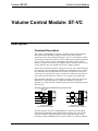
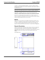
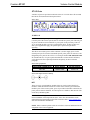
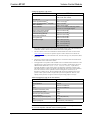
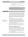
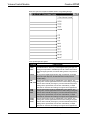
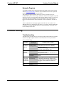
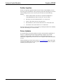
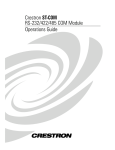
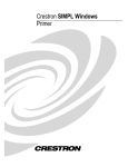
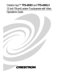
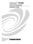
This document was prepared and written by the Technical Documentation department at: Crestron Electronics, Inc. 15 Volvo Drive Rockleigh, NJ 07647 1-888-CRESTRON Crestron ST-VC Volume Control Module Contents Volume Control Module: ST-VC 1 Description................................................................................................................................. 1 Functional Description ................................................................................................ 1 Models......................................................................................................................... 2 Physical Description.................................................................................................... 2 Leading Specifications............................................................................................................... 4 Setup .......................................................................................................................................... 6 Preparation for Use...................................................................................................... 6 Identity Code ............................................................................................................... 7 Programming ............................................................................................................................. 8 Programming with the Crestron AppBuilder............................................................... 8 Programming with SIMPL Windows.......................................................................... 8 ST-VC Symbol ............................................................................................................ 9 Example Program ...................................................................................................... 11 Problem Solving ...................................................................................................................... 11 Troubleshooting ........................................................................................................ 11 Further Inquiries........................................................................................................ 12 Future Updates .......................................................................................................... 12 Return and Warranty Policies.................................................................................................. 13 Merchandise Returns / Repair Service ...................................................................... 13 CRESTRON Limited Warranty ................................................................................ 13 Operations Guide - DOC. 5676A Contents • i Crestron ST-VC Volume Control Module Volume Control Module: ST-VC Description Functional Description The Volume Control Module is a digitally controlled 3-channel audio attenuator. Each channel has independent settings for volume, treble, bass, and mute. Transitions between any attenuation settings are “pop” free. The module is ideally suited to provide full audio control for systems without an IR-controlled integrated receiver. Choose a mixer, preamp, and amplifier. Then add a Volume Control Module to complete the system. In some applications the module's separate control of treble and bass may even eliminate the need for a graphic equalizer. Volume, bass, and treble ramp times, scaling, preset levels, and volume muting may be specified on a per-channel basis (within the specified hardware range). Volume, bass, and treble are fully independent of each other on each channel. All of these various aspects are specified in software. Volume, bass, and treble control may be sent to more than one channel via software so as to support stereo applications. Input impedance and balance are determined by external connections. Refer to the diagram below. Input and output are completely independent of each other. Therefore, it is possible to have a balanced input paired with an unbalanced output and vice-versa. Examples of Balanced and Unbalanced External Connections OPTIONAL 600 OHM TERMINATOR + X + G BALANCED INPUT BALANCED OUTPUT EXAMPLE + IN OUT X + - IN OUT G UNBALANCED 10K INPUT UNBALANCED OUTPUT EXAMPLE The treble and bass controls are independent from volume and are individually controlled for each channel. Each channel includes a muting relay with 104 dB attenuation. When the signal driving MUTEA goes high, the muting circuit is activated providing 104 dB drop from any preset volume level. Likewise channels Operations Guide - DOC. 5676A Volume Control Module: ST-VC • 1 Crestron ST-VC Volume Control Module “B” and “C” are driving MUTEB and MUTEC, respectively. When the muting signal goes low, the muting circuit is deactivated and the volume and tone returns to its original preset level. NOTE: MUTEALL is an override. All channels are muted when this signal is high. When it is low, the channels follow the state of MUTEA, MUTEB, and MUTEC. Each channel is equipped with protective relays that turn ON only after safe conditions are sustained by the electronic circuitry. This feature protects the output from “pops” caused by accidental power-down/power-up conditions to the ST-VC. If the ST-VC is under program control and the power is cycled to the ST-VC, it renews the volume, bass, and treble levels to the current program settings. The mute status (per channel and the mute-all) are also restored. Models There are two Crestron Volume Control Module configurations available: ST-VC and STI-VC. Configuration is based on the type of power availability. Use the STVC with a 120V power supply and the STI-VC with a 220V power supply. For purposes of this Operations Guide, the term ST-VC is used for either configuration. Physical Description The ST-VC, shown below, is housed in a black enclosure with silk-screened labels on the front and rear panels. On the front of the unit there are eight LEDs for indicating the unit’s current status. All connections are made on the back of the unit. There are four rubber feet on the base of the unit for stability and to prevent slippage. ST-VC Physical Views 1.500 in (3.810 cm) 6.134 in (15.580 cm) 6.322 in (16.058 cm) 6.940 in (17.628 cm) 7.066 in (17.948 cm) 1.700 in (4.318 cm) 2 • Volume Control Module: ST-VC Operations Guide - DOC. 5676A Crestron ST-VC Volume Control Module ST-VC Ports A number of ports are provided on the back of the ST-VC. Each has a silk-screened label. Refer to illustration and descriptions below. ST-VC Ports 12 VDC .5 A NOTE: An external power pack is not supplied with the ST-VC. When the ST-VC is used as part of the Cresnet system, there is no need for a power pack. The unit gets its power from the network connection. A power pack is only necessary if the STVC is used with the STS system or as a stand-alone device. If either of these two STS system applications apply, the optional power pack can be purchased separately. This direct current (DC) power socket connector is used to supply power via the external power pack. Crestron recommends specific power packs for its devices. The designated power pack for the ST-VC is Crestron part number PW-1205 (PWI-1210 for international use). If a power pack other than this Crestron model is obtained, verify that it meets the required specification and polarity as shown after this paragraph. Power Pack Specification CRESTRON POWER PACK INPUT SPECS OUTPUT SPECS PW-1205 PWI-1210 120VAC~60 hertz (Hz) 230VAC~50Hz 12VDC 0.5A 12VDC 1.0A Power Pack Output Connector Polarity NET These two 6-pin, 6-position RJ11 modular jacks are used to connect the ST-VC module to either the SmarTouch STS or Cresnet remote control system. When the module is part of the Cresnet system, power is provided via the NET connection; the power pack need not be attached. Two NET ports are available so that network units can be daisy-chained together. NOTE: When making network connections, refer to the latest revision of the Network Modular Cable Requirements (Doc. 5682). The documentation can be obtained from the Downloads section of the Crestron website (www.crestron.com). Search for the MODULAR.PDF file. NOTE: Most 4-connector phone cables are wired in a crisscross fashion and are not compatible with Crestron equipment. Operations Guide - DOC. 5676A Volume Control Module: ST-VC • 3 Volume Control Module Crestron ST-VC If power pack is attached when module is part of the Cresnet system, power is drawn from the power pack. The module does not load the network power, but the network power remains chained. G (Chassis Ground) Use this chassis GND screw to ground the unit to the amplifier and audio source common GND. Channels A - C Connect these balance/unbalanced input (IN) ports to the AUDIO OUTPUT of any A/V equipment that needs volume, treble, and bass control. Connect the balance/unbalanced output (OUT) ports to an amplifier. The output stage is disconnected by each relay and connects the + and - lines to the signal ground when muted. ST-VC Indicators There are eight LED indicators located on the front panel of the ST-VC. Refer to illustration and descriptions below. ST-VC Indicators PWR (Power) This green LED illuminates when power is supplied to the ST-VC. NET This yellow LED illuminates when communication between either the SmarTouch STS or Cresnet system and the ST-VC is established. Illumination indicates that the SIMPL program currently loaded has a network device defined at the same ID as the ST-VC. V & T (Volume & Tone) These red LEDs (one pair per channel) illuminate when there is volume (V) or tone (T, i.e., treble and bass) activity on any of the three channels. Activity includes increase, decrease, or mute. Leading Specifications The three tables after this paragrpah provide a summary of leading specifications for the ST-VC module and volume and tone particulars. 4 • Volume Control Module: ST-VC Operations Guide - DOC. 5676A Crestron ST-VC Volume Control Module Leading Specifications of the ST-VC SPECIFICATION Power Requirements DETAILS 12VDC external power pack or 24VDC, 0.25A, 6W - network Default NET ID 10 Crestron Application BuilderTM Crestron Application Builder TM TM Version 1.0.9 or later1 & 2 Templates ® Version 1.4 or later2 SIMPL Windows Crestron Database Version 1.40.07 or later2 Version 12.1.4 or later for SmarTouch Wizard support or 12.1.3 for regular support2 2-Series Control System Update3 CNMSX-AV/PRO Upgrade File Version C2-1008 or later4 Version 5.10.11x or later5 CNRACKX/-DP Upgrade File Version 5.10.11w or later5 CEN/CN-TVAV Update File Version 5.12.05v or later5 ST-CP Update File Version 4.01.00s or later5 Height: 1.70 in (4.31 cm) Dimensions & Weight Width: 7.07 in (17.95 cm) Depth: 6.32 in (16.06 cm) Weight: 2.20 lb (1.00 kg) 1 This product is supported in the Crestron Application Builder Software, both in the Residential and Commercial versions. Contact Crestron Customer Service for licensing details. 2 The latest software versions can be obtained from the Downloads section of the Crestron website (www.crestron.com). New users are required to register in order to obtain access to the FTP site. 3 Crestron 2-Series control systems include the AV2, AV2 with Card Cage, CP2, CP2E, PAC2, PRO2, and RACK2. 4 Filenames for 2-Series control system update files have a CUZ extension and can be obtained from the Downloads section of the Crestron website. 5 CNX upgrade files are required for either CNMSX-AV/Pro or CNRACKX/-DP. Filenames for CNX upgrade files have a UPZ extension and ST-CP files are in one EXE or zipped UPZ file. All can be obtained from the Downloads section of the Crestron website. Update files are specifically designed for certain control systems. If an update file is loaded into a control system other than the device for which it was intended, it may lockup the control system, which would then have to be returned to Crestron. Update files with an "S" designator are for the ST-CP, "V" designator for CEN/CN-TVAV, "W" for CNRACKX-DP, and "X" for CNMSX-AV/Pro control systems. Control systems are able to recognize and reject incorrect update files. However, when updating control systems, do not ignore Crestron Viewport warning prompts or messages. Volume Specifications of the ST-VC (Per Channel) SPECIFICATION DETAILS Input Impedance 10K or 600 Ohms Output Impedance 10 Ohms Input Balanced or Unbalanced Output Balanced or Unbalanced Total Harmonic Distortion (THD) -85 dB Hum and Noise (ref. 0 Dbv) -85 dB Maximum Input Level (Flat Mode) 4V rms Channel Separation -90 dB Attenuation Range (Excluding Mute) 0 to -76 dB (maximum) Mute -104 dB Frequency Response 8 Hz to 60 KHz (-3 dB minimum) NOTE: A chassis GND screw is provided in the back of the unit to ground the ST-VC to the amplifier and audio source common ground. Operations Guide - DOC. 5676A Volume Control Module: ST-VC • 5 Crestron ST-VC Volume Control Module Tone Specifications of the ST-VC (Per Channel) SPECIFICATION DETAILS Flatness (8 to 60 KHz flat mode) +/- 0.2 dB Bass Gain Range (100 Hz) +/- 12 dB Bass Step Size (100 Hz) 2 dB Treble Gain Range (10 KHz) Treble Step Size (10 KHz) +/- 12 dB 2 dB As of the date of manufacture, the Volume Control Module has been tested and found to comply with specifications for CE marking and Australian Compliance Mark. NOTE: These devices comply with part 15 of the FCC rules. Operation is subject to the following two conditions: (1) these devices may not cause harmful interference, and (2) these devices must accept any interference received, including interference that may cause undesired operation. Setup Preparation for Use Refer to the two hookup diagrams that follow this paragraph. The first diagram illustrates the connections to SmarTouch STS. The second diagram showns connections to the Cresnet system. Complete the connections in any order, regardless of whether the ST-VC is part of SmarTouch STS or the Cresnet system. SmarTouch STS Hookup Connections for ST-VC POWER PACK (500 mA) (1000 mA for STI-VC) 6 • Volume Control Module: ST-VC AUDIO OUT AMPLIFIER & AUDIO SOURCE COMMON GND NOTE: USE 2 FOOT SUPPLIED CABLE (CA15717) TO CONNECT ST-VC TO SMARTOUCH STS. A/V EQUIPMENT INPUT SMARTOUCH STS AMPLIFIER DAISY CHAIN TO EXPAND Operations Guide - DOC. 5676A Crestron ST-VC Volume Control Module Cresnet System Hookup Connections for ST-VC OPTIONAL POWER PACK (500 mA) (1000 mA for STI-VC) AUDIO OUT AMPLIFIER & AUDIO SOURCE COMMON GND NOTE: USE ST-CNB (SOLD SEPARATELY) TO CONNECT ST-VC TO CRESNET SYSTEM. A/V EQUIPMENT INPUT CRESNET SYSTEM AMPLIFIER DAISY CHAIN TO EXPAND Identity Code Every equipment and user interface within the network requires a unique identity code (NET ID). These codes are recognized by a two-digit hexadecimal number from 03 to FE. The NET ID of each unit must match an ID code specified in the SIMPL Windows program. The NET ID of each ST-VC has been factory set to 10. The NET IDs of multiple ST-VCs in the same system must be unique and changed from a PC via Viewport, which is available from SIMPL Windows or VisionTools™ Pro-e (VT Pro-e). NOTE: VT Pro-e is a Windows compatible software package for creating Crestron touchpanel screen designs. The method for changing the unit's NET ID is identical regardless of the software chosen. Complete the following steps to change the NET ID. Operations Guide - DOC. 5676A 1. Attach one of the ST-VCs to the control system (verify that the software is running). 2. From the SIMPL Windows or VT Pro-e menu, select Tools | Viewport to open the Crestron Viewport. 3. From the Viewport menu, select Functions | Set Network ID. The software checks the baud rate and then opens the "Set Network ID" window. 4. In the "Set Network ID" window, select the ST-VC from the Current Network Devices text window. 5. From the Choose the new network ID for the selected device (Hex): text box, select the new NET ID for the ST-VC. Volume Control Module: ST-VC • 7 Crestron ST-VC Volume Control Module 6. Click Set ID to initiate the change. This will display the "ID command has been sent" window. 7. In the "Command Complete" window, click OK. 8. In the Current Network Devices text window, verify the new NET ID code. 9. In the "Set Network ID" window, click Close. NOTE: The new NET ID code may also be verified by selecting Diagnostic | Report Network Devices in the Viewport (alternately, select F4). 10. Repeat this procedure for each ST-VC to be added to the network. Programming The ST-VC can be programmed using various Crestron tools. Crestron AppBuilder and SIMPL Windows define and set up the functions and actions appointed by the control system. The control system interprets the button presses on the touchpanel, carries out the command, and provides feedback to the touchpanel. The AppBuilder and SIMPL Windows are intended for users with different levels of programming knowledge. The flexibility of each tool is proportional to the degree of programming expertise (i.e., the more flexible, the more a programmer needs to know and account for). Of course, one can initiate programming using the easiest method (Crestron AppBuilder) and use advance techniques that are available from SIMPL Windows to customize the job. Programming with the Crestron AppBuilder Easiest method of programming that by itself does not offer the greatest amount of flexibility. The Crestron AppBuilder offers automatic programming for such residential and commercial applications as audio distribution, home theater, video conferencing, and lighting. The interface of this tool guides you through a few basic steps for designating rooms and specifying the control system, touchpanels, devices, and functionality. The Crestron AppBuilder then programs the system, including all touchpanel projects and control system logic. The Crestron AppBuilder is fully integrated with Crestron's suite of software development tools, including SIMPL Windows, VT Pro-e, Crestron Database, User IR Database, and User Modules Directory. The Crestron AppBuilder accesses these tools behind the scenes, enabling you to easily create robust systems. Programming with SIMPL Windows SIMPL (Symbol Intensive Master Programming Language) is an easy-to-use programing language that is completely integrated and compatible with all Crestron system hardware. The objects that are used in SIMPL are called symbols. SIMPL Windows offers drag and drop functionality in a familiar Windows environment. SIMPL Windows is Crestron's software for programming Crestron control systems. It provides a well-designed graphical environment with a number of workspaces (i.e., windows) in which a programmer can select, configure, program, test, and monitor a Crestron control system. The next three sections describe a ST-VC within SIMPL Windows. The first section provides initial configuration information, the second section identifies the ST-VC 8 • Volume Control Module: ST-VC Operations Guide - DOC. 5676A Crestron ST-VC Volume Control Module symbol and defines its inputs, and the final section provides the location of example program. NOTE: The following descriptions assume that the reader has knowledge of SIMPL Windows. If not, refer to the extensive help information provided with the software. Configure ST-VC Program To create a program with a ST-VC, refer to the table below for initial configuration information. Configure ST-VC Program SYMBOL FOLDER Device Library, Control Systems Device Library, Network Control Modules SYMBOL DROP REQUIRED WHERE Desired control system ST-VC System Views System Views, Cresnet Units ADDITIONAL SETUP Refer to the documentation supplied with the specific control system for additional setup information. CHANGE NET ID (OPTIONAL) Double-click on ST-VC (or single-click then right mouse-click) on ST-VC. Select Configure. Select NET ID then select desired hexadecimal ID. SIMPL is Crestron’s object-oriented programming language designated for easy implementation of the control system requirements. The objects that are used in SIMPL are called symbols. ST-VC Symbol The diagram after this paragraph shows the ST-VC symbol in SIMPL Windows. The table following the diagram lists the inputs and their functional descriptions. Operations Guide - DOC. 5676A Volume Control Module: ST-VC • 9 Crestron ST-VC Volume Control Module Detail View of the ST-VC Symbol in SIMPL Windows' Programming Manager ST-VC Symbol Input Descriptions INPUT(S) FUNCTION(S) Each channel (A through C) has a corresponding muting relay with 104 dB attenuation. When any of these digital inputs goes high, the muting circuit provides a 104 dB drop from the current volume level. When the signal goes low, the volume setting returns to its previous level. As long as this digital signal remains high, all channels are muted. muteall When this input drops low, all channels return to their previous volume setting. Each of these analog inputs are independent of one another. The volA, volB, volC analog value of each signal determines the volume setting of the given channel. Each channel (A through C) can have discrete ramp times, scaling factors, preset levels, and so forth. Alternatively, multiple channels can have the same settings to support stereo applications. Each of these analog inputs are independent of one another. The trebA, analog value of each signal determines the treble setting of the given trebB, channel. Each channel (A through C) can have discrete ramp times, trebC scaling factors, preset levels, and so forth. Alternatively, multiple channels can have the same settings to support stereo applications. Each of these analog inputs are independent of one another. The bassA, analog value of each signal determines the bass setting of the given bassB, channel. Each channel (A through C) can have discrete ramp times, bassC scaling factors, preset levels, and so forth. Alternatively, multiple channels can have the same settings to support stereo applications. mutea, muteb, mutec 10 • Volume Control Module: ST-VC Operations Guide - DOC. 5676A Crestron ST-VC Volume Control Module Example Program An example program can be obtained from the Downloads section of the Crestron website (www.crestron.com). Search for ST-VC.SMW. New users are required to register in order to obtain access to the FTP site. This example program illustrates control over a ST-VC network device in a CNMSX-PRO system. In the example, channels A and B are tied together to provide control over a stereo source that has a left and right channel. Channel C is for mono source that only has one channel, such as a microphone. The system also has a FLAT input which will take the bass and treble levels for channels A, B, and C to 50%. There is a MUTE ALL that simply toggles the MUTE ALL line on the ST-VC. When MUTE ALL is engaged, the mute states for A, B, and C are disregarded and all channels are muted. When MUTE ALL is released, channels A, B, and C will revert to their previous states. Problem Solving Troubleshooting The table below provides corrective action for possible trouble situations. If further assistance is required, please contact a Crestron customer service representative. ST-VC Troubleshooting TROUBLE POSSIBLE CAUSE(S) Green PWR ST-VC is not LED does not receiving power. illuminate. Yellow NET Improper NET ID. LED does not illuminate. Loose network connection. Channel (A, Improper B, or C) red programming. V/T LEDs do not illuminate. Hum on audio. Operations Guide - DOC. 5676A Grounding problem. CORRECTIVE ACTION Confirm that power pack securely plugged into outlet and that the connector is properly attached to the ST-VC. Verify that cables plugged into NET ports are secure (for Cresnet system only). Verify that ST-VC NET ID matches NET ID software program. Refer to "Identity Code" in this Operations Guide. Verify that cables plugged into NET ports are secure. Confirm signal names and programming logic so that LEDs respond when functions are activated. Refer to "Programming with SIMPL Windows" in this Operations Guide for an example. Either connect or remove chassis ground wire. Volume Control Module: ST-VC • 11 Crestron ST-VC Volume Control Module Further Inquiries If after reviewing this Operations Guide for the Volume Control Module, you can not locate specific information or have questions, please take advantage of Crestron's award winning customer service team in your area. Dial one of the following numbers. • In the US and Canada, call Crestron’s corporate headquarters at 1-888-CRESTRON [1-888-273-7876] or 1-201-767-3400. • In Europe, call Crestron International at +32-15-50-99-50. • In Asia, call Crestron Asia at +852-2341-2016. • In Latin America, call Crestron Latin America at +5255-5093-2160. • In Australia, call Crestron Pacific at +613-9480-2999. For local support from exclusive Crestron factory-trained personnel in New Zealand, call Amber Technologies at +649-410-8382. Future Updates As Crestron improves functions, adds new features, and extends the capabilities of the ST-VC, additional information and programming examples may be made available as manual updates. These updates are solely electronic and serve as intermediary supplements prior to the release of a complete technical documentation revision. The Downloads page of the Crestron website (www.crestron.com) directs the reader to the location and description of each update. Check the site periodically for update availability and its subjective value. 12 • Volume Control Module: ST-VC Operations Guide - DOC. 5676A Crestron ST-VC Volume Control Module Return and Warranty Policies Merchandise Returns / Repair Service 1. No merchandise may be returned for credit, exchange, or service without prior authorization from CRESTRON. To obtain warranty service for CRESTRON products, contact the factory and request an RMA (Return Merchandise Authorization) number. Enclose a note specifying the nature of the problem, name and phone number of contact person, RMA number, and return address. 2. Products may be returned for credit, exchange, or service with a CRESTRON Return Merchandise Authorization (RMA) number. Authorized returns must be shipped freight prepaid to CRESTRON, Cresskill, N.J., or its authorized subsidiaries, with RMA number clearly marked on the outside of all cartons. Shipments arriving freight collect or without an RMA number shall be subject to refusal. CRESTRON reserves the right in its sole and absolute discretion to charge a 15% restocking fee, plus shipping costs, on any products returned with an RMA. 3. Return freight charges following repair of items under warranty shall be paid by CRESTRON, shipping by standard ground carrier. In the event repairs are found to be nonwarranty, return freight costs shall be paid by the purchaser. CRESTRON Limited Warranty CRESTRON ELECTRONICS, Inc. warrants its products to be free from manufacturing defects in materials and workmanship under normal use for a period of three (3) years from the date of purchase from CRESTRON, with the following exceptions: disk drives and any other moving or rotating mechanical parts, pan/tilt heads and power supplies are covered for a period of one (1) year; touchscreen display and overlay components are covered for 90 days; batteries and incandescent lamps are not covered. This warranty extends to products purchased directly from CRESTRON or an authorized CRESTRON dealer. Purchasers should inquire of the dealer regarding the nature and extent of the dealer's warranty, if any. CRESTRON shall not be liable to honor the terms of this warranty if the product has been used in any application other than that for which it was intended, or if it has been subjected to misuse, accidental damage, modification, or improper installation procedures. Furthermore, this warranty does not cover any product that has had the serial number altered, defaced, or removed. This warranty shall be the sole and exclusive remedy to the original purchaser. In no event shall CRESTRON be liable for incidental or consequential damages of any kind (property or economic damages inclusive) arising from the sale or use of this equipment. CRESTRON is not liable for any claim made by a third party or made by the purchaser for a third party. CRESTRON shall, at its option, repair or replace any product found defective, without charge for parts or labor. Repaired or replaced equipment and parts supplied under this warranty shall be covered only by the unexpired portion of the warranty. Except as expressly set forth in this warranty, CRESTRON makes no other warranties, expressed or implied, nor authorizes any other party to offer any other party to offer any warranty, including any implied warranties of merchantability or fitness for a particular purpose. Any implied warranties that may be imposed by law are limited to the terms of this limited warranty. This warranty statement supercedes all previous warranties. Trademark Information All brand names, product names, and trademarks are the sole property of their respective owners. Windows is a registered trademark of Microsoft Corporation. Windows95/98/Me/XP and WindowsNT/2000 are trademarks of Microsoft Corporation Operations Guide - DOC. 5676A Volume Control Module: ST-VC • 13 Crestron ST-VC Volume Control Module This page intentionally left blank. 14 • Volume Control Module: ST-VC Operations Guide - DOC. 5676A Crestron ST-VC Volume Control Module This page intentionally left blank. Operations Guide – Doc. 5676A Volume Control Module: ST-VC • 15 Crestron Electronics, Inc. 15 Volvo Drive Rockleigh, NJ 07647 Tel: 888.CRESTRON Fax: 201.767.7576 www.crestron.com Operations Guide – DOC. 5676A 02.02 Specifications subject to change without notice.