1
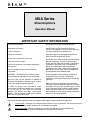
MXA Series
Mixer/Amplifiers
Operation Manual
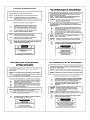
IMPORTANT SAFETY INFORMATION
Read these instructions.
Do not block any of the ventilation openings.
Keep these instructions.
Do not install near any heat sources such as
radiators, heat registers, stoves, or other apparatus
(including amplifiers) that produce heat.
Heed all warnings.
Follow all instructions.
Unplug this apparatus during lightning storms or
when unused for long periods of time.
Do not use this apparatus near water.
Clean only with a dry cloth.
Only use attachments / accessories specified by
manufacturer.
Install in accordance with the manufacturers
instructions.
WARNING - To reduce the risk of electric shock,
do not expose this apparatus to rain or moisture.
Apparatus shall not be exposed to dripping or
splashing and no objects filled with liquids, such as
vases, shall be placed on the apparatus.
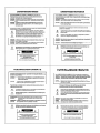
In order to comply with international safety
requirements for operating temperature, clearance
of at least 5cm or 1.97" must be maintained
between this device and other rack-mounted
devices. This spacing will ensure that all exposed
metal surfaces are safe to touch.
Do not defeat the safety purpose of the polarized or
grounding-type plug. A polarized plug has two
blades with one wider than the other. A grounding
type plug has two blades and a third grounding
prong. The wide blade or the third prong are
provided for your safety. When the provided plug
does not fit into your outlet, consult an electrician
for replacement of the obsolete outlet.
Protect the power cord from being walked on or
pinched particularly at plugs, convenience
receptacles, and the point where they exit from the
apparatus.
Refer all servicing to qualified service personnel.
Servicing is required when the apparatus has been
damaged in any way, such as power-supply cord or
plug is damaged, liquid has been spilled or objects
have fallen into the apparatus, the apparatus has
been exposed to rain or moisture, does not operate
normally, or has been dropped.
Explanation of safety related markings and symbols which appear on the outside of the apparatus.
Lightning Bolt: Hazardous Live voltages present when this unit is in operation. Do not touch terminals
marked with this symbol while the unit is connected to live power.
Exclamation Point: Replace components (i.e. fuses) only with the values specified by the
manufacturer. Failure to do so will compromise safe operation of this unit.
Biamp Systems, 10074 S.W. Arctic Drive, Beaverton, Oregon 97005 U.S.A.
(503) 641-7287
www.biamp.com
19Mar07
MXA Series
TABLE OF CONTENTS
Front & Rear Panel Features
INTRODUCTION
pgs. 2 & 3
Specifications
pg. 4
Block Diagram
pg. 5
Warranty
The MXA Series of mixer/amplifiers combines a versatile 6-input mic/line mixer
with either 35, 75, 150, or 300 Watt amplification. Mixing functions include
mic/line/tel inputs, selectable automatic & manual channel muting, channel
priority assignment, remote level control, tone control, a built-in limiter, an
internal chime, phantom power, MOH output, and extensive patching. The
amplifier includes an output transformer, and provides rated power into direct
or distributed speaker systems. The MXA Series carries a five-year warranty.
MXA Series features include:
♦ integrated mixer, power amplifier, and output transformer
♦ six electronically balanced microphone/line input channels
♦ channel 1 selectable for 600 ohm transformer tel input
♦ rear panel trim, pad, & peak indicator on each input channel
♦ +48 Volt phantom power selectable on each input channel
♦ automatic muting of selected channels (-20dB or -80dB)
♦ automatic muting triggered by selected priority channels
♦ manual muting of selected channels (-20dB or -80dB)
♦ manual muting triggered from remote contact closures
♦ remote control of master level via rear panel terminals
♦ integral output limiter with rear panel threshold control
♦ recessed tone controls plus rear panel low-cut filter switch
♦ patch points for signal processing and systems interconnect
♦ Music On Hold output with independent level, from input 6
♦ 35, 75, 150, or 300 watts into direct or distributed systems
♦ front panel indicators for power, signal, peak, temp, & fault
♦ internal pre-announcement chime tone with level control
♦ input/output connections provided on barrier strip terminals
♦ covered by Biamp Systems' five-year warranty
♦
marked and CSA tested to UL 60065
1
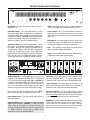
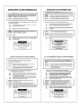
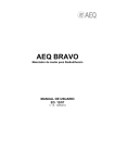
FRONT & REAR PANEL FEATURES
MXA300
0
signal
peak
on
temp
fault
1
2
3
4
5
6
0
+
+
bass
treble
master
On Indicator: This green LED remains lit when AC power is
applied to the unit.
NOTE: Signal/Peak indicators will turn off during Temp/Fault
conditions (see Signal/Peak & Temp/Fault Indicators above).
Signal/Clip Indicator: This 2-color LED indicates the signal
level for the amplifier. When the LED is green, the amplifier has
signal (above -30dB). When the LED is red, the amplifier signal
is clipping (max. power). CAUTION: Signal levels should be
adjusted to avoid clipping. Clipping can cause distortion, overtemperature conditions, and even loudspeaker damage.
Level (Channels 1~6): These controls adjust the amount of
signal sent from the individual input channels to the mixer
output. Optimum Level setting is near the 12 o'clock position
(unity gain).
Level (Master): This control adjusts the amount of signal sent
from the mixer output to the amplifier input. The Master Level
control is used to adjust the overall volume of the system.
Temp/Fault Indicator (not present on model MXA35): This red
LED indicates over-temperature and output fault conditions for
the amplifier. When the LED remains lit, the amplifier has an
over-temperature condition. When the LED is flashing, the
amplifier has an output fault condition. Either condition will
temporarily de-activate the amplifier, causing the Signal/Peak
LED to turn off as well. The amplifier will attempt to self-reset
once the over-temperature or output fault condition is resolved.
MXA300
CAUTION:
Risk of fire replace fuse only
with same type
UL 60065
Treble: This screwdriver control adjusts the high-frequencies
("Treble") at the mixer output (±12dB @ 10kHz).
channel 6
mute/chime
BIAMP SYSTEMS
Bass: This screwdriver control adjusts the low-frequencies
("Bass") at the mixer output (±12dB @ 50Hz).
remote
level
control
Music
On
Hold
output
Music On
Hold level
min
max
pre out
EQ in
link
C +10V
off
low cut
off
on
off
on
channel 5
on
on
on
on
-20dB
phantom pwr
priority
auto mute
manual mute
-80dB
peak
channel 4
on
on
on
on
-20dB
phantom pwr
priority
auto mute
manual mute
-80dB
peak
channel 3
on
on
on
on
-20dB
phantom pwr
priority
auto mute
manual mute
-80dB
peak
channel 2
on
on
on
on
-20dB
phantom pwr
priority
auto mute
manual mute
-80dB
peak
channel 1
on
on
on
on
-20dB
phantom pwr
priority
auto mute
manual mute
-80dB
on
on
on
on
-20dB
phantom pwr
priority
auto mute
manual mute
-80dB
peak
peak
link
min
max
min
chime
level
max
min
trim
auto mute
sensitivity
line out amp in
min
max
trim
min
max
trim
min
max
trim
min
max
trim
min
trim
max
min
max
~ 120/240VAC
WARNING: RISK OF HAZARDOUS ENERGY.
SEE INSTALLATION MANUAL.
120V
FUSE
FUSE
O
limiter
threshold
max
50-60Hz 300W
FUSE: T 8A/4A L 250V 120V/240V
class 3
wiring
100V
70V
Designed in Oregon, U.S.A.
25V
comin India
xfmr
Assembled
class 2 wiring
4Ω
mic/line
gnd
input
6
input
input
5
input
4
input
3
input
2
tel
input
1
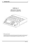
AC Power Entrance: The switch applies power to the unit. The
receptacle accepts the detachable Power Cord. The Power Cord
is for connection to three-prong grounded outlets. CAUTION: Do
not remove or defeat the ground prong on the Power Cord, as this
constitutes a shock hazard. Equipment shall be connected to a
mains socket outlet with a protective earthing connection. Plug is
main disconnecting device and it shall remain readily operable.
Chime Level: This control adjusts the volume level of a chime
tone (see Mute/Chime below). To turn the chime tone off
completely, set this control to the counter-clockwise position (min).
Fuse: Replace Fuse with same type and value only. NOTE: If
the Fuse continues to blow, the amplifier may require service.
Auto Mute Sensitivity: This control adjusts the level at which
signals from "priority" channels will automatically trigger muting of
selected non-priority channels (see DIP Switches on next page).
To increase auto mute sensitivity, turn this control clockwise.
Limiter Threshold: This control adjusts the threshold level at
which the internal limiter circuit is activated. To turn the limiter off
completely, set this control to the clockwise position (max).
Power Selector Switch: This switch selects either 120 Volt or
240 Volt AC operation.
Mute/Chime: This terminal (plus the adjacent d terminal) allows
manual muting of selected channels via an external switch or
contact closure (see DIP Switches on next page). When the
Chime Level control is turned up (on), a pre-announcement chime
tone will also be activated by the switch or contact closure.
Output Connector: These screw terminals provide the speaker
outputs from the amplifier. CAUTION: To reduce the risk of
electric shock, do not perform any servicing other than that
contained in this Operation Manual unless you are qualified to do
so. Output connections must be made by qualified service
personnel only (refer to the Installation Manual).
2
DIP Switches: The five DIP switches above each input are used
to assign specific functions to those individual channels. Phantom
Pwr assigns +48 Volts DC phantom power to the channel input, for
powering condenser microphones. CAUTION: To avoid damage
to equipment, assign phantom power only on channels being used
as inputs for conderser microphones. Priority assigns a channel to
priority. When signal is present in a priority channel, any nonpriority channels which are assigned to Auto Mute will be muted by
their selected amounts (see below). NOTE: A priority channel
cannot be auto muted by another priority channel, but a priority
channel can be manually muted (see below). Auto Mute assigns a
(non-priority) channel to be muted whenever signal is present in
any priority channel. Manual Mute assigns a channel to be muted
whenever the Mute/Chime terminal is shorted to ground via a
switch or contact closure. Mute Level assigns the amount of
muting (-80dB or -20dB) which is applied to a channel, when
triggered by either Auto Mute or Manual Mute. NOTE: -80dB is
effectively complete muting (off), whereas -20dB is audible
attenuation (ducking).
Remote Level Control: These two terminals (plus the adjacent
"d" terminal) provide remote volume control of the master level.
An internal voltage controlled amplifier (VCA) allows remote
control from up to 2000 feet away, using any 5k~50kΩ linear taper
potentiometer and/or switch to provide adjustment and/or muting of
the master level. Potentiometers are wired with high-side to
(+10V), low-side to (d), and wiper to (C). Mute switches simply
connect (C) to (d), with no (+10V) connection required.
Music On Hold Level: This control adjusts the volume level of a
Music On Hold output (see below). To turn the output off
completely, set this control to the counter-clockwise position (min).
Music On Hold Output: These three terminals provide a
balanced line-level output as a source for phone systems. This
signal is derived from input channel 6. For unbalanced output,
wire high to (+) and ground to (d), leaving (-) unconnected.
Pre Out & EQ In: These two RCA jacks provide pre-tone patching
for external equipment. When used as an 'insert point' for external
signal processors, set the associated Link switch to the (off)
position. When using Pre Out for recording and/or EQ In for
stacking, the Link switch may remain in the (on) position.
Peak: These red LEDs will light whenever channel signal levels
reach +10dB (8dB below clipping). Use this feature to aid in
proper adjustment of Trim (see below).
Trim: These screw-driver controls set the channel gain (0~60dB)
to compensate for different input signal levels (mic or line). Adjust
these controls so the channel Peak indictors flash only on
occasional peaks.
Line Out & Amp In: These two RCA jacks provide post-master
patching for external equipment. When used as an 'insert point' for
external signal processors, set the associated Link switch to the
(off) position. When using Line Out for external amps and/or Amp
In for stacking, the Link switch may remain in the (on) position.
Mic/Line or Tel Switch (Channel 1 only): This switch selects the
proper impedance and gain for either mic/line input signals or input
from 600 ohm sources. The input for Channel 1 includes an
isolation transformer, which allows connection to most telephone
system audio ports.
Low Cut: This switch controls a low-cut filter (12dB/octave @
125Hz) at the amplifier input. CAUTION: To avoid output fault
conditions, Low Cut must be used when driving 25/70/100 Volt
speaker systems (see Installation Manual). Also, any other system
equalization affecting frequencies below 125Hz should remain flat
or be used as cut-only. This also precludes boosting of the Bass
control (see above) in these applications.
Inputs: These plug-in barrier strips provide a balanced input
connection for each channel. For unbalanced input, wire high to
(+) and ground to both (-) & (d). The input for Channel 1 includes
an isolation transformer.
3
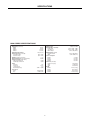
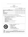
SPECIFICATIONS
MXA SERIES SPECIFICATIONS
Output Power (4 ohm load):
MXA35
MXA75
MXA150
MXA300
Output Transformer Voltages:
Frequency Response (+0/-1.5dB):
4 ohm direct output
transformer output
THD+Noise (1kHz @ rated power):
Equivalent Input Noise (150 ohm termination):
Signal-to-Noise Ratio (20Hz~20kHz):
0dBu input, minimum trim
-60dBu input, maximum trim
Limiter:
attack time
release time
compression ratio
threshold adjust range
Tone Controls:
Treble
Bass
High-Pass Filter:
Input Impedance / Sensitivity:
mic/line inputs
Tel (Channel 1)
EQ In & Amp In
Output Impedance / Level:
Pre Out & Line Out
MOH
Power Consumption:
MXA35
MXA75
MXA150
MXA300
Dimensions (all models):
height (2 rack spaces)
width
depth
Weight:
MXA35
MXA75
MXA150
MXA300
35 watts
75 watts
150 watts
300 watts
25V, 70V, 100V
20Hz ~ 20kHz
50Hz ~ 20kHz
< 0.2%
-126dBu
> 90dB
> 66dB
2 ms
500 ms
20:1
-10dBu ~ +18dBu
±12dB @ 10kHz
±12dB @ 50Hz
4
12dB/oct. @ 125Hz
10kΩ / -71dBu ~ -11dBu
600Ω / -71dBu ~ -11dBu
10kΩ / 0dBu (774mV)
100Ω / 0dBu (774mV)
200Ω / +6dBu (1.5V)
< 75 watts
< 100 watts
< 150 watts
< 300 watts
3.47" (88 mm)
19" (483 mm)
9.8" (249 mm)
17.5 lbs. (7.9 kg)
19 lbs. (8.6 kg)
21 lbs. (9.1 kg)
23 lbs. (10.5 kg)
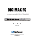
BLOCK DIAGRAM
5
WARRANTY
BIAMP SYSTEMS IS PLEASED TO EXTEND THE FOLLOWING 5-YEAR LIMITED WARRANTY TO THE
ORIGINAL PURCHASER OF THE PROFESSIONAL SOUND EQUIPMENT DESCRIBED IN THIS MANUAL
1. BIAMP Systems warrants to the original purchaser of new
products that the product will be free from defects in material
and workmanship for a period of 5 YEARS from the date of
purchase from an authorized BIAMP Systems dealer, subject to
the terms and conditions set forth below.
2. If you notify BIAMP during the warranty period that a BIAMP
Systems product fails to comply with the warranty, BIAMP
Systems will repair or replace, at BIAMP Systems' option, the
nonconforming product. As a condition to receiving the benefits
of this warranty, you must provide BIAMP Systems with
documentation that establishes that you were the original
purchaser of the products. Such evidence may consist of your
sales receipt from an authorized BIAMP Systems dealer.
Transportation and insurance charges to and from the BIAMP
Systems factory for warranty service shall be your responsibility.
3. This warranty will be VOID if the serial number has been
removed or defaced; or if the product has been altered,
subjected to damage, abuse or rental usage, repaired by any
person not authorized by BIAMP Systems to make repairs; or
installed in any manner that does not comply with BIAMP
Systems' recommendations.
4. Electro-mechanical fans, electrolytic capacitors, and normal
wear and tear of items such as paint, knobs, handles, and
covers are not covered under this warranty.
5.
THIS WARRANTY IS IN LIEU OF ALL OTHER
WARRANTIES, EXPRESS OR IMPLIED. BIAMP SYSTEMS
DISCLAIMS ALL OTHER WARRANTIES, EXPRESS OR
IMPLIED, INCLUDING, BUT NOT LIMITED TO, IMPLIED
WARRANTIES OF MERCHANTABILITY AND FITNESS FOR A
PARTICULAR PURPOSE.
6. The remedies set forth herein shall be the purchaser's sole
and exclusive remedies with respect to any defective product.
7. No agent, employee, distributor or dealer of Biamp Systems
is authorized to modify this warranty or to make additional
warranties on behalf of Biamp Systems.
statements,
representations or warranties made by any dealer do not
constitute warranties by Biamp Systems. Biamp Systems shall
not be responsible or liable for any statement, representation or
warranty made by any dealer or other person.
8. No action for breach of this warranty may be commenced
more than one year after the expiration of this warranty.
9. BIAMP SYSTEMS SHALL NOT BE LIABLE FOR SPECIAL,
INDIRECT, INCIDENTAL, OR CONSEQUENTIAL DAMAGES,
INCLUDING LOST PROFITS OR LOSS OF USE ARISING
OUT OF THE PURCHASE, SALE, OR USE OF THE
PRODUCTS, EVEN IF BIAMP SYSTEMS WAS ADVISED OF
THE POSSIBILITY OF SUCH DAMAGES.
Biamp Systems
10074 S.W. Arctic Drive
Beaverton, Oregon 97005
(503) 641-7287
585.0188.90A