1
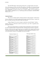
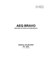
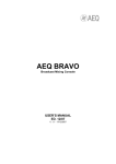
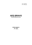
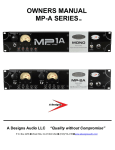
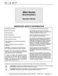
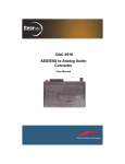
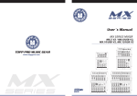
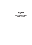
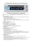
J
C
F
A
U
D
I
O
DA 8- V
DA8-V USER MANUAL
JCF AUDIO, LLC.
11247 CAMARILLO ST.
NORTH HOLLYWOOD, CA 91602
WWW.JCFAUDIO.COM
[email protected]
11 2 4 7 C a m a r i l l o S t . N . H o l l y w o o d , C A 9 1 6 0 2 • w w w. j c f a u d i o . c o m
JCF Audio
DA8-V
Safety Information
Do not repair, modify, service this device except in the manner in which it is described
in this manual. Doing so can endanger the user and others as well as void the warranty.
Fuses should be replaced with the exact values and sizes stated in the manual.
JCF Audio, LLC accepts no responsibility for legal actions or for direct, incidental, or
consequential damages that may result from improper installation, configuration, or use
of the DA8-V.
Warnings:
Lethal potential present inside DA8-V and Power supplies
even without power applied.
Do not connect power supplies to wall without connections
to DA8-V main unit secure.
Do not remove any lids with power applied.
DA8-V must be earthed to provide compliance with most
electrical codes.
J C F A u d i o
DA8-V
1
JCF Audio
Overview
The DA8-V is an 8 channel Digital to Analog converter that utilizes the AKM AK4359 in combination with a tube line stage that was inspired by the Ampex 351 reproduce circuitry.
The unit accepts the industry standard AES/EBU protocol on a DB25 connector with an additional courtesy turn-around. The AES/EBU DB25’s follow the most commonly used “triangle”
or Tascam® pinout. The AES/EBU inputs operate in single-wire mode exclusively at all sampling frequencies. The DA8-V derives its sync source from the incoming AES/EBU stream under all conditions.
The DA8-V has two analog outputs each coming from two separate, floating sources (with factory configuration). This can aid in installations where the outputs of the DA8-V must be connected to multiple devices.
0 dBu is referenced to 0.775 vrms for this manual
Front Panel Controls
Level Adujstments - These level adjustments for the output of the device. The fully clock
wise position provides no attenuation and the fully counter-clockwise position provides approximately 20 db of attenuation. Calibration level details are listed in the Specifications section.
Receiver Error - This LED indicates that the AES/EBU input signal to the unit is invalid.
Operation - This switch must be in the X1 / X2 position for operation up to and including
96kHz. The switch must be in the X4 position for operation @ 176.4kHz and 192kHz.
Reset - This switch resets the digital section of the device.
J C F A u d i o
DA8-V
2
JCF Audio
Rear Panel
Analog Power - This 4 pin XLR jack is for connection to the supplied analog power supply.
The pinout is as follows:
Pin 1 Pin 2 -
}
Pin 3 - BPin 4 - B+
6 VAC 4.8A
}
~300 VDC 0.125A idle
Digital Power - This 4 pin connector is for connection to the supplied digital power supply.
The pinout is as follows:
Pin 1 Pin 2 Pin 3 Pin 4 -
}
~10 VAC
}
~10 VAC
J C F A u d i o
DA8-V
3
JCF Audio
AES/EBU Input The popularity of DB25 for bi-directional AES/EBU communication presents a
unique challenge to the user attempting to connect devices to a system that only utilize
one direction (as in the case of the DA8-V). The most common situation is that one will
go to plug in the converter for the first time and find that their DAW already has something connected to it’s AES/EBU DB25 port. Since AES/EBU is, for the most part, a
single source/single load system, a likely scenario would be that the user is using
what’s there already to get information from an A/D converter or other digital devices
into their DAW. In these cases we have offered the following solution:
The top DB25 port is the Standard Input port (see photo above). The included
AES/EBU cable can connect any Tascam® AES/EBU port to the DA8-V’s top port. The
bottom port is a Courtesy Thru port that can take the previously existing cabling to
other devices if necessary.
J C F A u d i o
DA8-V
4
JCF Audio
The AES/EBU input is self-syncing and the Ch. 1/2 input stream’s recovered
clock is the reference for the unit under all conditions. This allows for setup-and-forget
operation on all sampling rates up to and including 96kHz. The front panel control labeled “Operation” must be set to X4 for use at 176.4kHz, 192kHz and surrounding varispeed variants. Channels 3, 4, 5, 6, 7, and 8 may not be used without a valid AES/EBU
stream on Ch. 1/2.
Analog Outputs There are two analog output connectors present on the rear panel. As the unit is
factory configured, each output is galvanically separate and fully floating. Analog Output #1 is closest to the fan. (See DA8-V Rear View picture)
Analog Output #1 has circuit common connections on each channel. Analog
Output #2 does not. The latter is useful in cases where a “pin 1 lift” is required across
all 8 output channels.
There is an internal option to strap the output transformer in series which will
provide an additional 6db of output level and a commensurate increase in output impedance. In this case the output connectors are in parallel, each coming from the seriesconnected transformer secondary. Regardless of output strapping, the presence of circuit common-per-connector is unchanged. (See below picture)
J C F A u d i o
DA8-V
5
JCF Audio
Fan - The fan hole in the rear of the unit and the air inlet grate at the front of the unit
should remain unobstructed at all times. Proper airflow is essential to keep the tubes
and surrounding circuitry at a reasonable operating temperature. Do not defeat the fan
for any reason.
Power Supplies:
Both Analog and Digital power supplies should be kept away from the main unit
and their chassises should not touch each other, the DA8-V nor any other object . Both
units should rest on their rubber feet at all times. The analog supply’s fan ports should
be completely unobstructed and away from objects that generate and/or are susceptible
to heat. Proper airflow is important to keep the rectifier tube cool and functioning for
its expected tube life. Do not defeat the fans for any reason.
The rectifier tube included with the analog power supply is shipped wrapped in
bubble wrap inside the supply enclosure itself. The bottom 6 screws should be removed, the bubble wrap discarded, and the tube inserted in its socket. The bottom
plate should then be replaced and all 6 screws refitted. Do not perform this operation
with power applied.
The power supplies should never be connected to the wall without
all their lids secure and connections to the DA8-V made first. Failure to
do so can result in serious injury.
J C F A u d i o
DA8-V
6
JCF Audio
Cabling:
The DA8-V ships with 3 included cables:
A male to male 4-pin cable for transferring power from the included analog
power supply to the main unit. This cable is wired “straight through”. Pin 1 to Pin 1,
etc.
A female to female circular “ham connector” cable for transferring power from
the included digital power supply to the main unit. This cable is wired “straight
through”. Pin 1 to Pin 1, etc.
A 5’ standard AES to AES db25 crossover cable. This cable is for transferring
Tascam® compatible pinned AES/EBU signals to and through the main unit.
Specifications
D/A Calibration Range - (w/ factory split parallel output)
MIN
MAX
Level fully counterclockwise
Level fully clockwise
0dBfs = +4.8dBu at outputs
0dBfs = +24.8dBu at outputs
-0.8dBfs = +4dBu at outputs
-20.8dBfs = +4dBu at outputs
-18dBFS = -13.2 dBu at outputs
-18dBFS = +6.8 dBu at outputs
D/A Calibration Range - (w/ series outputs)
MIN
MAX
Level fully counterclockwise
Level fully clockwise
0dBfs = +10.8dBu at outputs
0dBfs = +30.8.dBu at outputs
-6.8dBfs = +4dBu at outputs
-26.8dBfs = +4dBu at outputs
-18dBFS = -7.2 dBu at outputs
-18dBFS = +12.8 dBu at outputs
J C F A u d i o
DA8-V
7
JCF Audio
De-emphasis is not supported anywhere in the DA8-V.
Power Consumption:
100W Idle
Tube Compliment:
8 - 12AX7
8 - 12AU7
1 - 5R4 (Located in Analog Power Supply) Life Expectancy is ~18 months on this tube.
THD+N
(48kHz, 400 to 18k BW, 1kHz tone)
-20dBFS to 0 out: 0.03%
-10dBFS to +10 out: 0.008%
-30dBFS to -10 out: 0.1%
-35dBFS to -10 out: 0.15%
(192kHz, 400 to 18k BW, 1kHz tone)
-20dBFS
-10dBFS to +10 out: 0.03%
-30dBFS to -10 out: 0.08%
-35dBFS to -10 out: 0.15%
(192kHz, 10 to 200k BW, 1kHz tone)
-20dBFS to 0 out: 0.057%
-10dBFS to +10 out: 0.035%
-30dBFS to -10 out: 0.18%
-35dBFS to -10 out: 0.3%
to 0 out: 0.03%
J C F A u d i o
DA8-V
8
JCF Audio
Frequency Response (No output load)
@ 44.1kHz: 20Hz to 20kHz +/- 1.5dB
@ 88.2kHz: 20Hz to 40kHz +/- 1.5dB
@ 176.4kHz: 20Hz to 80kHz +/- 1.5dB
DAC residual noise (No BW limiting, No attenuation)
192k: - < -51dBu
96k: - < -51dBu
48k: - < -51dBu
DAC residual noise (22k upper BW limit, “Lev” fully clockwise)
192k: -71dBu
96k: -70dBu
48k: -65dBu
Shipping weight
67 lbs. 30”X 24”X10”
Max Dimensions
L: 14.5”
W: 19”
H: 3.5”
J C F A u d i o
DA8-V
9
JCF Audio
Fuses: 2x 500ma 5x20mm on digital section, inside unit
1x 3A, 3AG (Analog Supply) 1x 1A, 3AG (Digital Supply)
Notes:
The 12AU7 output tubes are recommended to be replaced every 24 months. The
5R4 rectifier tube does quite a bit of power handling and as a result it may need to be
replaced every 18 months. The 12AX7 input tubes may outlive styrofoam.
These figures can vary wildly with usage. It would be difficult to find an operational variable that does not affect tube life.
Feature list
•Ampex 351 inspired output stage
• Simple self-clocking operation @ all frequencies
• 1 additional courtesy turn-around DB25 AES/EBU port
• ~20dB front panel calibration range control
• Sensible output stage current for good performance and long tube life
• High quality Cinemag CM-9600-T output transformer
• Uses commonly available tubes 12AX7,12AU7
• Ships with 5’ standard AES/EBU crossover cabling
• 1 Year Limited Warranty
J C F A u d i o
DA8-V
10
JCF Audio
FCC Compliance:
This device complies with part 15 of the FCC Rules. Operation is subject to the following two
conditions:
(1) This device may not cause harmful interference, and
(2) This device must accept any interference received, including interference that may cause undesired operation.
Warranty
JCF Audio 1-Year Limited Warranty
JCF Audio LLC. “JCF Audio” warrants this product to be free of defects in material and assembly for a period of one year for parts and labor from the date of original purchase. This warranty is enforceable only by the original retail purchaser and cannot be transferred or assigned
without express permission of JCF Audio.
During the warranty period JCF Audio shall, at its exclusive option, either repair or replace free
of charge any product that proves to be defective on inspection by JCF Audio or its authorized
service representative. In all cases disputes concerning this warranty shall be resolved as prescribed by law. To obtain warranty service, the purchaser must contact JCF Audio to obtain instructions where to send the unit for service. All authorized returns must be sent to JCF Audio
or an authorized JCF Audio repair facility postage prepaid, insured and properly packaged.
This warranty does not cover claims for damage due to abuse, neglect, modification or attempted repair by unauthorized personnel, and is limited to failures arising during normal use
that are due to defects in material or workmanship in the product.
Proof of purchase must be verified in the form of a bill of sale or some other positive proof that
the product is within the warranty period upon JCF Audio’s request.
JCF Audio reserves the right to update any unit returned for repair. JCF Audio reserves the
right to change or improve design of the product at any time without prior notice.
Any implied warranties including implied warranties of merchantability and fitness for a particular purpose are limited in duration to the length of this limited warranty. Some states do not
allow limitations on how long an implied warranty lasts, so the above limitation may not apply
to you.
JCF Audio will not be liable for incidental, consequential, indirect or other damages resulting
from the breach of any express or implied warranty, including damage to property, damage
based on inconvenience, downtime, loss of personal property, and to the extent permitted by
law, damages for personal injury or death.
J C F A u d i o
DA8-V
11
JCF Audio
Some states do allow the exclusion or limitation of incidental or consequential damages, so the
above limitation or exclusion may not apply to you.
This warranty gives you specific legal rights, and you may also have other rights which vary
from state to state.
This warranty only applies to products sold in the United States of America. The terms of this
warranty shall only apply within the country of sale. Without limiting the foregoing, repairs
under this warranty shall be made only by a duly authorized JCF Audio service representative
or by JCF Audio itself. For warranty information in other countries, please refer to the dealer.
J C F A u d i o
DA8-V
12