1
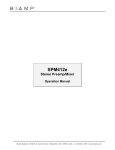
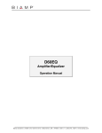
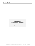
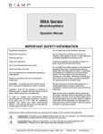
SPM412e
Stereo Preamp/Mixer
Operation Manual
Biamp Systems, 10074 S.W. Arctic Drive, Beaverton, Oregon 97005 U.S.A.
(503) 641-7287
www.biamp.com
blank
19Mar07
SPM412e
INTRODUCTION
TABLE OF CONTENTS
Front Panel Features
pg. 2
Rear Panel Features
pg. 3
Modifications
pg. 4 & 5
Remote Control
pg. 6 & 7
Applications
pgs. 8 & 9
Block Diagram
pg. 10
Specifications
pg. 11
Warranty
The SPM412e Stereo Preamp/Mixer provides four stereo line inputs, one
mic/line input, and two independent outputs. With input source selection,
automatic page-over muting, and remote control functions, the SPM412e is
ideally suited for applications such as restaurants, bars, meeting rooms,
aerobics studios, and school gymnasiums. The SPM412e is extremely
versatile, yet cost-effective, and is easy to install and operate.
SPM412e features include:
♦ four stereo line inputs with trim controls & RCA connectors
♦ balanced mic/line input on plug-in barrier strip connector
♦ trim, pad, peak indicator, & level control on the mic/line input
♦ +24 volt phantom power switchable on the mic/line input
♦ balanced stereo main output on plug-in barrier strip connector
♦ balanced mono zone output on plug-in barrier strip connector
♦ front panel push-buttons select stereo inputs & adjust main level
♦ simultaneous selection of multiple stereo inputs from front panel
♦ front panel display shows stereo input selections & main level
♦ treble, bass, and balance controls for the stereo main output
♦ rear panel switch defeats treble & bass at stereo main output
♦ rear panel switch converts the stereo main output to mono
♦ limiter with threshold control for the stereo main output
♦ front panel rotary level control for the mono zone output
♦ automatic talkover muting when the mic/line input is in use
♦ internal jumpers assign mic/line input pre or post treble & bass
♦ internal jumpers assign mic/line input pre or post main level
♦ internal jumpers assign mic/line input to main and/or zone
♦ internal jumpers assign stereo line inputs to main and/or zone
♦ internal jumpers assign talkover muting to main and/or zone
♦ separate internal talkover mute adjustments for main and zone
♦ infrared, wall-mount, custom, or third-party remote controllers
♦ wall-mount ‘Controller’ overrides commands from front panel
♦ remote control affects stereo input selection & main level
♦ default settings can be defined & stored for recall at power-up
♦ incorporates AES recommended grounding practices
♦
marked and UL / C-UL listed power source
♦ covered by Biamp Systems' five-year warranty
1
FRONT PANEL FEATURES
channel select
down
mute
up
min
main level
max
SPM412e
mic level
(1)
1
3
2
(2)
4
bass
treble
balance
zone level
(3)
(4)
(5)
(6)
(7)
(7) Main Level: These three momentary push-buttons adjust the
overall level of signals sent to the Main Output (see Main Output
on pg. 3). The Down push-button decreases level and the Up
push-button increases level. As long as either push-button is
being pressed, signal level will continue to change until the
minimum or maximum level has been reached. It takes
approximately five seconds to adjust from one extreme to the
other. When the Mute push-button is pressed, the output is muted
(turned off). Pressing the Mute push-button again will gradually
un-mute the output. Pressing the Up push-button (while the output
is muted) will immediately un-mute the output and begin increasing
the level. However, Pressing the Down push-button (while the
output is muted) will cause there to be a decreased level when the
output is un-muted. Whenever power to the SPM412e is turned off
or interrupted, Main Level settings (except Mute) are retained in
non-volatile memory for recall when power is turned back on.
However, a default level setting can be defined and stored for
recall at power-up (see Power Switch below). The 9-segment LED
display indicates the relative level setting for the Main Output. The
display is not a signal level meter. The output has approximately
10dB of gain at ‘max’, 70dB of attenuation at ‘min’, and 0dB of gain
(unity) when seven of the nine LEDs are lit. When Main Output is
muted, only the ‘min’ LED will be lit. When Main Output is unmuted, the display will return to the current level setting. Pressing
the Down button (while the output is muted) will cause there to be
a decreased level when the output is un-muted, however, the
display will remain at ‘min’ until the output is actually un-muted.
NOTE: See Remote Control on page 6.
(1) Mic Level: This rotary control adjusts the level of the Mic
Input signal sent to the Main Output and Zone Output sections.
Mic Input signal can be assigned to the Main and/or Zone Outputs
individually, plus it can be assigned to the Main Output as pre/post
Tone and pre/post Main Level (see Modifications on pgs. 4 & 5).
(2) Channel Select: These four momentary push-buttons select
which Stereo Line Input signal is sent to the Main Output and Zone
Output sections (see Stereo Input Assign on pg. 4). To select a
desired Stereo Line Input, press the corresponding push-button.
The adjacent LED indicator will light, indicating the selection. More
than one Stereo Line Input can be selected at a time by pressing
the corresponding front panel push-buttons simultaneously.
Whenever power to the SPM412e is turned off or interrupted,
Channel Select settings are retained in non-volatile memory for
recall when power is turned back on. However, default settings
can be defined and stored for recall at power-up (see Power
Switch below). NOTE: See Remote Control on page 6.
(3) Bass: This rotary control adjusts the low-frequency (Bass)
content of the Main Output signals. When this control is centered
(12 o’clock), Bass is normal (flat). When turned counter-clockwise,
Bass is decreased (-12dB @ 200Hz max.). When turned
clockwise, Bass is increased (+12dB @ 200Hz max.). A rear
panel switch allows the Bass & Treble controls to be bypassed
(see Tone on pg. 3).
(4) Treble: This rotary control adjusts the high-frequency (Treble)
content of the Main Output signals. When this control is centered
(12 o’clock), Treble is normal (flat). When turned counterclockwise, Treble is decreased (-12dB @ 5kHz max.). When
turned clockwise, Treble is increased (+12dB @ 5kHz max.). A
rear panel switch allows the Bass & Treble controls to be
bypassed (see Tone on pg. 3).
NOTE: Whenever power to the SPM412e is removed or
interrupted, Channel Select & Main Level settings (except Mute)
are retained in non-volatile memory for recall when power is
restored. Default Channel Select and Main Level settings can be
defined & stored for recall at power-up. To define & store default
settings: 1) Select the default Stereo Line Input(s). 2) Adjust
Main Level to the default setting. 3) Allow 3 seconds of inactivity
(settings are stored in non-volatile memory). 4) Turn unit off (unplug from AC power). 5) Press and hold the Mute push-button
while restoring power. 6) Release the Mute push-button. 7)
Cycle power off & on again (confirms the default power-up settings
are stored). These Channel Select & Main Level settings are now
stored in non-volatile memory, and will be recalled whenever
power to the SPM412e is turned off & on (interrupted). NOTE:
This process can be reversed (so the SPM412e will again recall
the most recent settings at power up) by repeating steps 4~7.
(5) Balance: This rotary control adjusts the stereo balance of the
Main Output signals. When this control is centered (12 o’clock),
left and right signal levels are equal. When turned counterclockwise, left signal level increases and right signal level
decreases. When turned clockwise, right signal level increases
and left signal level decreases. Use the Balance control to
compensate for uneven speaker coverage.
(6) Zone Level: This rotary control adjusts the overall level of
signals sent to the Zone Output (see Zone Output on pg. 3).
2
REAR PANEL FEATURES
BIAMP SYSTEMS
designed and assembled in the USA
www.biamp.com
R
limit
threshold
input 4
level
main
L
input 3
R
level
L
input 2
R
level
L
input 1
R
level
L
R
mute
main
signal
L
gnd
gnd
zone
IR3
remote
IR2
~
27V
50/60 Hz
mic
trim
pad
tone
(1)
(2)
stereo
mono
(3)
(4)
phtm
pwr
+10
lo
hi
15 watts
class 2 wiring
gnd
limit
(5)
(6)
out
in
bypass
(7)
(8)
(9)
off
on
(10) (11) (12)
(8) Inputs 1~4: These RCA connectors provide the unbalanced
Stereo Line Inputs for line-level signals (-10dBu or +4dBu). Use
these inputs to accept signals from cassette, CD, VCR, tuner,
satellite, cable, computer, etc. Inputs 1~4 each have a screwdriver
adjustable control for setting level of the corresponding Stereo Line
Input signal. Use these controls to compensate for different input
signal levels. For best performance, reduce level only on inputs
which are higher than the others. These controls are factory set
fully clockwise for +10dB of gain. This is appropriate for most
inputs such as CD, cassette, tuner, etc. (-10dBu nominal levels).
(1) Power Cord: The external transformer provides 27 Volts AC
to the SPM412e, and is detachable via a 5-pin DIN connector.
Two internal ‘self-resetting’ fuses provide AC over-current fault
protection (not user servicable). These fuses will attempt to re-set
when power is turned off. If these fuses do not re-set, or continue
to trip, it is an indication that the SPM412e requires service.
(2) Remote: When the adjacent switch is released, the ‘IR2’,
‘IR3’, & ‘gnd’ terminals can be used for connection of optional
remote controls (see Remote Control on pg. 6). When the
adjacent switch is depressed, the ‘hi’, ‘lo’ & ‘gnd’ terminals can be
used as a ‘Translator’ input for remote control via third-party
controllers which utilize a carrier-stripped serial bit-stream (see
Translator on pg. 7).
(9) Mic / Line Input: This balanced input will accept either lowimpedance microphone or line-level input signals. For unbalanced
use, connect signal to (+) and ground to both (d) & (-). Three
additional terminals are provided for ‘page-over’ muting of the
Stereo Line Input signals. By wiring ‘signal present’ to ‘mute’,
automatic muting of the currently selected Stereo Line Input will
occur whenever signal is present at the Mic/Line Input. Manual
muting of the currently selected Stereo Line Input is achieved by
wiring a switch or contact-closure between ‘mute’ and the adjacent
‘gnd’ terminal. From the factory, ‘page-over’ muting is set for
-40dB, and is assigned to both the Main Output and the Zone
Output (see Mute Assign & Mute Adjust on pg. 4).
(3) Zone Output: This balanced output carries a mono sum of
the selected Stereo Line Input signal, and the Mic/Line Input signal
(see Modifications on pg. 4). Zone Output provides 6dB of
additional gain when balanced. For unbalanced use, connect
signal to (+) and ground to (d), leaving (-) unconnected. When
Mic/Line Input signal is present, stereo input signal may be muted
automatically by up to 40dB (see Mic/Line Input on this page).
(4) Main Output: This balanced stereo output carries the
selected Stereo Line Input signal, and the Mic/Line Input signal
(see Modifications on pg. 4 & 5). Main Output provides 6dB of
additional gain when balanced. For unbalanced use, connect
signal to (+) and ground to (d), leaving (-) unconnected. When
Mic/Line Input signal is present, stereo input signal may be muted
automatically by up to 40dB (see Mic/Line Input on this page).
(10) Pad: When depressed, this switch reduces the Mic/Line
Input signal level by 30dB (see Mic/Line Input above). Use this
switch when Mic/Line Input signal levels exceed the normal
operating range of the Trim control, or whenever a line-level input
signal is connected.
(11) Trim: This screwdriver adjustable control sets gain at the
Mic/Line Input (see Mic/Line Input above). Use this control to
compensate for different input signal levels. For best performance,
adjust Trim so the adjacent +10 indicator flashes only on
occasional peaks in signal level.
(5) Limit Threshold: This screwdriver adjustable control sets the
threshold level for the internal limiter. When Main Output signal
levels exceed this threshold, the limiter is activated and the
adjacent Limit indicator will light. Limit Threshold range is -4dBu to
+24dBu (balanced) or -10dBu to +18dBu (unbalanced). Use the
limiter to set maximum levels for sound system protection.
(12) Phantom Power: When depressed, this switch provides +24
Volt Phantom Power to the Mic/Line Input (see Mic/Line Input
above). Phantom Power is for powering condenser microphones.
CAUTION: Never turn Phantom Power on when line-level signal
devices are connected to the Mic/Line Input. Always turn power
off and Mic Level down before switching Phantom Power or
making connections to the Mic/Line Input.
(6) Main (Stereo / Mono): When depressed, this switch
combines the stereo left & right Main Output signals into a mono
sum, which is then sent to both left & right Main Outputs. When
Main Output is set for mono operation, the front panel Balance
control still affects the relative level of the left & right Main Outputs.
(7) Tone (Bypass): When depressed, this switch bypasses the
front panel Bass & Treble controls. Tone Bypass defeats any tone
adjustments made to the Main Output signals.
3
MODIFICATIONS
To access internal modifications, first disconnect power to the unit. Then lay the unit on a flat surface with the front panel facing forward
and the top panel facing up. Remove the top panel (eight screws along the sides and rear; one screw centered behind the front panel).
Modifications are at the center of the circuit board, starting from the left side (see diagrams below). Modifications require no soldering.
MIC/LINE ASSIGN: Internal jumpers are provided to assign Mic/Line Input signal to the Main Output and the Zone Output, independently.
From the factory, Mic/Line Input signal is assigned to both the Main Output and the Zone Output. To un-assign Mic/Line Input signal from
the Main Output, move jumper P2 (‘MIC INPUT TO MAIN OUTPUT’) forward one pin to the ‘OUT’ position, using needle-nose pliers. To
un-assign Mic/Line Input signal from the Zone Output, move jumper P1 (‘MIC INPUT TO ZONE OUTPUT’) forward one pin to the ‘OUT’
position. If desired, Mic/Line Input signal may be un-assigned from both outputs. A jumper is also provided to assign Mic/Line Input signal
to the Main Output pre or post tone (Treble & Bass). From the factory, Mic/Line Input signal is assigned post-tone (not affected by Treble
& Bass). To assign Mic/Line Input signal pre-tone (affected by Treble & Bass), move jumper P3 (‘MIC INPUT TO MAIN OUTPUTS’)
forward one pin to the ‘PRE-TONE’ position, using needle-nose pliers. See also Mic Pre/Post VCA on page 5.
P2
P3
IN
MIC INPUT TO MAIN OUTPUTS
OUT
POST-TONE (SEE VCA JUMPERS)
MIC INPUT TO MAIN OUTPUTS
PRE-TONE
P1
IN
MIC INPUT TO ZONE OUTPUT
OUT
STEREO INPUT ASSIGN: Internal jumpers are provided to assign Stereo Line Input signals to the Main Output and the Zone Output,
independently. From the factory, Stereo Line Input signal is assigned to both the Main Output and the Zone Output. To un-assign Stereo
Line Input signal from the Main Output, move jumpers P4 & P6 (‘LEFT INPUT TO MAIN OUTPUT’ & ‘RIGHT INPUT TO MAIN OUTPUT’)
forward one pin to the ‘OUT’ position, using needle-nose pliers. If desired, left & right Stereo Line Input signals may be un-assigned from
the Main Output independently. To un-assign Stereo Line Input signal from the Zone Output, move jumper P8 (‘STEREO INPUTS TO
ZONE OUTPUT’) forward one pin to the ‘OUT’ position, using needle-nose pliers.
MUTE ASSIGN: Internal jumpers are provided to assign muting of Stereo Line Input signals at the Main Output and the Zone Output,
independently. From the factory, muting is assigned to both the Main Output and the Zone Output. To un-assign muting from the Main
Output, move jumpers P5 & P7 (‘LEFT INPUT MUTING’ & ‘RIGHT INPUT MUTING’) forward one pin to the ‘OFF’ position, using needlenose pliers. If desired, muting may be un-assigned from left & right Main Outputs independently. To un-assign muting from the Zone
Output, move jumper P9 (‘STEREO TO ZONE MUTING’) forward one pin to the ‘OFF’ position, using needle-nose pliers. If desired,
muting may be un-assigned from both the Main Output and the Zone Output.
NOTE: Mic/Line Assign, Stereo Input Assign, and Mute Assign are totally independent of each other. Therefore, Mic/Line Input signal may
be un-assigned from either output, without un-assigning the muting function from that output. Likewise, the muting function may be unassigned from either output, without un-assigning Mic/Line Input signal from that output. To un-assign both Mic/Line Input signal and the
muting function from a given output, both jumpers must be moved. Also, Mic/Line Input signal may be un-assigned from the Main Output
and Stereo Line Input signal may be un-assigned from the Zone Output, creating separate outputs for Stereo Line Input and mono Mic/Line
Input signals. This is useful when separate high-fidelity (music) and distributed (speech) speaker systems are desired.
MUTE ADJUST: Internal screwdriver adjustable controls are provided to adjust the amount of muting applied to Stereo Line Input signals.
From the factory, -40dB of muting is set for Stereo Line Input signals. To decrease the amount of muting at the Main Output, adjust
controls R75 & R76 (‘MUTE TRIM’) clockwise. To decrease the amount of muting at the Zone Output, adjust control R77 (‘MUTE TRIM’)
clockwise. These controls are totally independent. Therefore, different amounts of muting may be set for each output. However, muting is
usually set the same for left & right Main Outputs. The muting range is adjustable from -40dB (max.) to -4dB (min.).
P4
P5
P6
IN
ON
OUT
OFF
R75
P8
ON
OUT
OFF
R76
4
ON
OUT
OFF
STEREO TO ZONE
MUTING
MUTE TRIM
(CCW = MAX)
P9
IN
STEREO INPUTS
TO ZONE OUTPUT
RIGHT INPUT
MUTING
RIGHT INPUT
TO MAIN OUTPUT
LEFT INPUT
MUTING
LEFT INPUT
TO MAIN OUTPUT
MUTE TRIM
(CCW = MAX)
P7
IN
R77
MUTE TRIM
(CCW = MAX)
MODIFICATIONS
MIC PRE/POST VCA: Internal jumpers are provided to assign Mic/Line Input signal to the Main Output pre or post VCA (Main Level).
From the factory, Mic/Line Input signal is assigned pre-VCA (affected by Main Level). To assign Mic/Line Input signal post-VCA (not
affected by Main Level), move jumpers P10 & P11 (‘L’ & ‘R’) backward one pin to the ‘POST’ position, using needle-nose pliers. These
jumpers are totally independent of each other. Therefore, Mic/Line Input signal may be assigned pre or post VCA for left & right Main
Outputs independently.. However, this assignment is usually the same for both left & right Main Outputs. CAUTION: When assigned
Post-VCA, Mic/Line Input signal can trigger, but will not be affected by, the internal limiter circuit. Mic/Line Input signal cannot be assigned
Post-VCA unless it is also assigned Post-Tone.
P11
POST
R
PRE
P10
POST
L
PRE
MICROPHONE POST TONE CONFIG JUMPERS (P10,P11):
CONFIGURE THESE JUMPERS FOR LEFT AND RIGHT
OUTPUTS WHENEVER MIC IS SELECTED POST-TONE.
OPTIONS ARE POST AND PRE OUTPUT LEVEL CONTROL
5
REMOTE CONTROL
Infrared and wall-mount remote control is optional for the SPM412e. Remote control affects Channel Select and Main Level (plus mute).
Remote control may be added at any time, and does not require the SPM412e to be modified, opened, or removed from a rack. There are
two remote control devices: a hand-held Infrared Transmitter and a wall-mount push-button Controller with status indicators & infrared
detector (see diagrams below). Remote control of the SPM412e is also possible via third-party controllers, which utilize a carrier-stripped
serial bit-stream (see Translator on next page).
Infrared Transmitter: The Transmitter is a hand-held controller, which transmits infrared codes unique to
Biamp. Therefore, the Transmitter should not affect any other infrared controlled equipment (such as TVs or
VCRs). Likewise, other infrared controllers will not provide proper control of Biamp equipment. The Transmitter
requires two AAA batteries, which are included with the unit (user installed). The Transmitter has twenty-eight
buttons, only seven of which control functions on the SPM412e. Channel Select buttons provide the same
function as those on the SPM412e front panel (except that only one stereo line input can be selected at a time).
When a stereo line input is selected with the Transmitter, the associated LED indicator on the SPM412e front
panel will light. Main Level buttons provide the same function as Main Level buttons on the SPM412e. For best
results, there should be an unobstructed line-of-sight from Transmitter to Receiver. The Transmitter will operate
up to 30 feet from a Controller panel. When infrared information is transmitted to the Receiver, the LED indicator
inside the Receiver will light. NOTE: The Infrared Transmitter requires an Infrared Receiver (or Controller) to
allow infrared control.
Controller: The Controller is a ‘hard-wired’ control, which is powered by the SPM412e. There
are no batteries to wear out, and it is not easily lost or stolen. The Controller may be wired up to
2000 feet from the SPM412e, using 2-conductor shielded cable (not included). The Controller
overrides all similar commands which might be initiated from the front panel of the SPM412e
(see NOTE below). To install Controller, first remove mounting box from circuit board & front
panel. Route cable through "knock-out" hole on rear of mounting box. Install mounting box in
wall or panel. Three screw terminals on circuit board (‘GND’, ‘IR2’, & ‘IR3’) correspond to
‘Remote’ terminals on rear panel of SPM412e. Connect cable shield to ‘GND’ terminals at each
end. Use conductors to connect ‘IR2’ to ‘IR2’ & ‘IR3’ to ‘IR3’. Install circuit board & front panel
on mounting box. The Controller has seven buttons which control functions on the SPM412e.
The Channel Select buttons & indicators provide the same functions as those on the SPM412e
front panel (including the ability to select more than one stereo line input at a time). The Main
Level buttons & display provide the same functions as Main Level on the SPM412e front panel
(except that only a single indicator will light to display the level setting, and it will dim when the
output is muted). The Controller also includes an infrared detector, which allows it to operate as
an Infrared Receiver as well. NOTE: Two additional screw terminals (‘GND’ & ‘KEY SWI’) allow
an external key-switch (or contact-closure) to ‘lock-out’ control of Channel Select and/or Main
Level functions from the Controller. These functions will then be temporarily available from the
SPM412e front panel, as long as the ‘lock-out’ is maintained. When ‘lock-out’ is released, the
Controller memory will then reassert its previous settings on the SPM412e. A 4-gang DIP switch
on the Controller circuit board allows custom functions to be assigned, such as Channel Select
‘lock-out’, Main Level ‘lock-out’, key-lock triggering, and infrared detector defeat (instructions
included with Controller).
6
1
CHANNEL SELECT
2
3
MUTE
VOL
VOL
ADVANTAGE SPM412e
SPM412e Controller
max
1
2
3
4
MUTE
min
CHANNEL SELECT
4
MAIN LEVEL
MAIN
LEVEL
REMOTE CONTROL
Translator: When the adjacent switch is depressed, the ‘hi’, ‘lo’, & ‘gnd’ terminals on the SPM412e rear panel Remote connector provide
a ‘Translator’ input, which allows third-party controllers (such as AMX®, CRESTRON®, and RANGERTM) to directly interface to, and control,
the SPM412e. To interface a third-party controller to the Translator input, connect the controller output to either the ‘hi’ or ‘lo’ terminal on
the SPM412e (depending upon high or low idle signal from the controller) and the controller ground to the SPM412e ‘gnd’ terminal. For
reliable operation it is recommended that the SPM412e be located within 10 feet of the third-party controller. The Translator input is
compatible with bi-polar signal voltages (such as -12V to +12V RS-232 signal levels) as well as uni-polar signal voltages (such as 0V to
+5V TTL or CMOS logic signals). The maximum input voltage range for the Translator input is -15 Volts DC to +15 Volts DC, The
switching threshold for the Translator input is approximately +2 Volts DC (at idle-high terminal) or +3 Volts DC (at idle-low terminal). Input
impedance for the Translator signal is about 6k ohms. The third-party controller must be programmed to output a ‘carrier-stripped’ bitstream in the Biamp format (contact the controller manufacturer to determine if their device driver library supports the Biamp format).
AMX is a registered trademark of AMX Corporation.
CRESTRON is a registered trademark of CRESTRON Electronics, Inc.
RANGER is a registered trademark of Rauland-Borg Corp.
7
APPLICATIONS
Restaurant/Lounge
SPM412e
main
BIAMP SYSTEMS
designed and assembled in the USA
www.biamp.com
R
limit
threshold
input 4
level
main
L
input 3
R
level
L
input 2
R
level
L
input 1
R
level
L
R
mute
L
signal
gnd
zone
IR3
IR2
remote
gnd
~
27V
50/60 Hz
mic
trim
pad
tone
phtm
pwr
+10
stereo
mono
lo
gnd
15 watts
class 2 wiring
hi
limit
out
in
bypass
off
on
SPM412e Controller
max
1
Satellite
2
Tape Deck
3
4
MUTE
min
CHANNEL SELECT
MAIN LEVEL
Stereo
Amplifier
Controller
Mono
Amplifier
Cable
To
Lounge
(stereo)
CD Player
Hostess
Microphone
To
Restaurant
(mono)
5) Connect the stereo line-level program sources to Inputs 1~4.
1) Un-assign Mic/Line Input signal and muting from the Zone
Output (restaurant). See Modifications on pg. 4. This allows
‘paging’ to occur only in the Main Output (lounge).
6) Adjust Level 1~4 (reduce level only on inputs which are
higher than the others).
2) Connect Zone Output to the input of the amplifier driving the
restaurant speakers.
7) Adjust Main Level, Zone Level, and Limit Threshold for
desired maximum levels.
3) Connect Main Output to the inputs of the amplifier driving
the lounge speakers.
8) Set Trim & Pad (+10 LED flash only on peaks). Adjust Mic
Level for desired paging level.
4) Connect the ‘paging’ microphone to the Mic/Line Input, with
the push-to-talk switch wired across the ‘Mute’ & ‘Gnd’
terminals. This allows switch-activated ‘page-over’ muting.
9) Connect an optional Controller to the Remote terminals.
Mount the Controller in a location to accept push-button and/or
infrared commands.
8
APPLICATIONS
Boardroom
SPM412e
main
BIAMP SYSTEMS
designed and assembled in the USA
www.biamp.com
R
limit
threshold
input 4
level
main
input 3
R
L
level
L
input 2
R
level
input 1
R
L
mute
L
level
R
L
mic
signal
gnd
IR2
zone
IR3
remote
gnd
~
27V
50/60 Hz
trim
hi
gnd
lo
limit
15 watts
class 2 wiring
phtm
pwr
pad
tone
+10
stereo
mono
out
in
bypass
off
on
Playback
VCR
Tape Deck
SPM412e Controller
max
1
CD Player
2
3
4
MUTE
min
MAIN LEVEL
main
an affiliate of
Rauland-Borg Corp.
logic
outputs
expansion
aux
outputs
main patch
patch
ON
ON
patch
input
stack in
patch
input
ON
8
patch
input
ON
7
patch
input
ON
6
patch
input
ON
5
patch
patch
input
ON
4
input
ON
3
input
ON
2
pad
ungated
phantom
duck ch8
patch pre
Portland, Oregon
DC out
pad
ungated
phantom
duck ch8
patch pre
BIAMP SYSTEMS
~
27V
50/60 Hz
15 watts
class 2 wiring ±12VDC
pad
ungated
phantom
duck ch8
patch pre
autoONE
pad
ungated
phantom
duck ch8
patch pre
Boardroom
Speakers
(stereo)
pad
ungated
phantom
duck ch8
patch pre
Stereo
Amplifier
pad
ungated
phantom
duck ch8
patch pre
Tele-Conferencing
Feed
(mono)
an er Board
rm ak Members
i
a e
Ch Sp
pad
ungated
phantom
duck ch8
patch pre
Controller
Video
Camera
slave
-12db
hp filter
last mic
aux post
Recording
VCR
pad
ungated
phantom
aux off
patch pre
CHANNEL SELECT
1
1) Connect Zone Output to the input of a teleconferencing
system. This allows interactive meetings, training seminars, and
presentations to be fed to remote locations.
4) Connect the stereo line-level program sources to Inputs 1~4,
and adjust Level 1~4 (reduce level only on inputs which are
higher than the others).
2) Connect Main Output to the inputs of the amplifier driving
the boardroom speakers. A separate tap from Main Output can
be used to feed the audio inputs of a VCR, when recording
training seminars or presentations for future viewing. A
distribution amplifier,
such as a BIAMP DA28R, may be
desired for multiple isolated feeds.
5) Adjust Main Level, Zone Level, and Limit Threshold for
desired maximum levels.
3) Connect an automatic or mic/line mixer, such as a BIAMP
autoONE or 801 to the Mic/Line Input. Connect a wire across
the ‘Mute’ & ‘Signal Present’ terminals for voice-activated
muting.
7) Connect an optional Controller to the Remote terminals.
Mount the Controller in a location to accept push-button and/or
infrared commands.
6) Set microphone mixer output level. Set Trim & Pad so the
+10 indicator flashes only on occasional peaks. Adjust Mic
Level for desired overall microphone levels.
9
BLOCK DIAGRAM
Zone
Level
L
Σ
1
Mute
R
Tone
Defeat
2
Mute
Mic
Σ
R
Switch
Matrix
▼
Mono/
Stereo
Σ
L
STEREO
LINE
INPUTS
1~4
+
-
Mic
+
-
VCA
Mic
Treble
& Bass
Mic
Bal
+
-
VCA
▼
L
Σ
3
R
Limit
L
4
R
Threshold
Level
Control
Logic
1
2
3
4
up
GND
translator
mute
IR2 / high
down
Channel
Select
Logic
IR3 / low
REMOTE
Min
Main Level
Reference
Meter
Max
+24V
Phantom
Power
+10
Trim
MIC/LINE
INPUT
+
-
30dB
Pad
Mic/Line
Preamp
▼
signal present
▼
mute
▼
Mic
Level
Signal
Present
SPM412e Block Diagram
Mute
Logic
10
ZONE
OUTPUT
L
MAIN
OUTPUT
R
SPECIFICATIONS
Frequency Response (20Hz-20kHz @ +4dBu):
+0/-0.5dB
Total Harmonic Distortion (20Hz-20kHz @ +4dBu):
< 0.1%
Output Noise (20Hz-20kHz @ nominal levels):
< -85dBu
Equivalent Input Noise (20Hz-20kHz, 150Ω termination @ Mic/Line Input):
Maximum Gain (Mic/Line Input to Main Output):
< -125dBu
80dB
Input Trim Gain Range:
Mic/Line Input (30dB Pad out)
+60dB to +20dB
Stereo Line Inputs 1~4
+10dB to -50dB
Input Impedance:
Mic/Line Input (balanced)
1.7k ohms
Stereo Line Inputs 1~4 (unbalanced)
7k ohms
Maximum Input:
Mic/Line Input (balanced)
+27dBu
Stereo Line Inputs 1~4 (unbalanced)
+27dBu
Output Impedance:
Main Output (balanced)
200 ohms
Zone Output (balanced)
200 ohms
Maximum Output:
Main Output (balanced)
+24dBu
Zone Output (balanced)
+24dBu
Phantom Power (Mic/Line Input only):
+24 Volts DC
Power Consumption:
10 Watts max.
Power Requirements:
115/230VAC 50/60Hz
Dimensions:
Height (1 rack space)
1.75 inches (44mm)
Width
19 inches (483mm)
Depth
7.25 inches (178mm)
Weight:
6 lbs. (2.72kg)
11
WARRANTY
BIAMP SYSTEMS IS PLEASED TO EXTEND THE FOLLOWING 5-YEAR LIMITED WARRANTY TO THE
ORIGINAL PURCHASER OF THE PROFESSIONAL SOUND EQUIPMENT DESCRIBED IN THIS MANUAL
1. BIAMP Systems warrants to the original purchaser of new
products that the product will be free from defects in material
and workmanship for a period of 5 YEARS from the date of
purchase from an authorized BIAMP Systems dealer, subject to
the terms and conditions set forth below.
2. If you notify BIAMP during the warranty period that a BIAMP
Systems product fails to comply with the warranty, BIAMP
Systems will repair or replace, at BIAMP Systems' option, the
nonconforming product. As a condition to receiving the benefits
of this warranty, you must provide BIAMP Systems with
documentation that establishes that you were the original
purchaser of the products. Such evidence may consist of your
sales receipt from an authorized BIAMP Systems dealer.
Transportation and insurance charges to and from the BIAMP
Systems factory for warranty service shall be your responsibility.
3. This warranty will be VOID if the serial number has been
removed or defaced; or if the product has been altered,
subjected to damage, abuse or rental usage, repaired by any
person not authorized by BIAMP Systems to make repairs; or
installed in any manner that does not comply with BIAMP
Systems' recommendations.
4. Electro-mechanical fans, electrolytic capacitors, and normal
wear and tear of items such as paint, knobs, handles, and
covers are not covered under this warranty.
5.
THIS WARRANTY IS IN LIEU OF ALL OTHER
WARRANTIES, EXPRESS OR IMPLIED. BIAMP SYSTEMS
DISCLAIMS ALL OTHER WARRANTIES, EXPRESS OR
IMPLIED, INCLUDING, BUT NOT LIMITED TO, IMPLIED
WARRANTIES OF MERCHANTABILITY AND FITNESS FOR A
PARTICULAR PURPOSE.
6. The remedies set forth herein shall be the purchaser's sole
and exclusive remedies with respect to any defective product.
7. No agent, employee, distributor or dealer of Biamp Systems
is authorized to modify this warranty or to make additional
warranties on behalf of Biamp Systems.
statements,
representations or warranties made by any dealer do not
constitute warranties by Biamp Systems. Biamp Systems shall
not be responsible or liable for any statement, representation or
warranty made by any dealer or other person.
8. No action for breach of this warranty may be commenced
more than one year after the expiration of this warranty.
9. BIAMP SYSTEMS SHALL NOT BE LIABLE FOR SPECIAL,
INDIRECT, INCIDENTAL, OR CONSEQUENTIAL DAMAGES,
INCLUDING LOST PROFITS OR LOSS OF USE ARISING
OUT OF THE PURCHASE, SALE, OR USE OF THE
PRODUCTS, EVEN IF BIAMP SYSTEMS WAS ADVISED OF
THE POSSIBILITY OF SUCH DAMAGES.
Biamp Systems
10074 S.W. Arctic Drive
Beaverton, Oregon 97005
(503) 641-7287
585.0130.90A