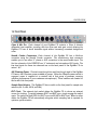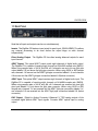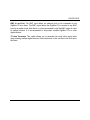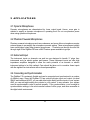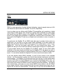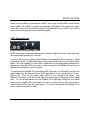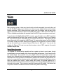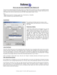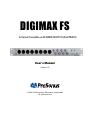
1
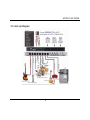
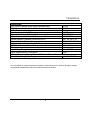
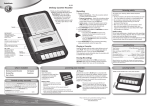
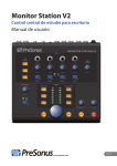
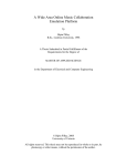
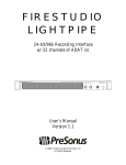
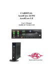
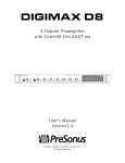
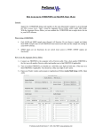
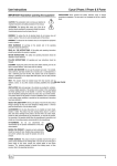
DIGIMAX FS
8-Channel Preamplifier with 24-bit/96k ADAT I/O (dual SMUX)
User’s Manual
Version 1.0
© 2006, PreSonus Audio Electronics, Incorporated.
All rights reserved.
W A R R A N T Y
PreSonus Limited Warranty
PreSonus Audio Electronics Inc. warrants this product to be free of defects in material and workmanship for a period
of one year from the date of original retail purchase. This warranty is enforceable only by the original retail
purchaser. To be protected by this warranty, the purchaser must complete and return the enclosed warranty card
within 14 days of purchase. During the warranty period PreSonus shall, at its sole and absolute option, either repair
or replace, free of charge, any product that proves to be defective on inspection by PreSonus or its authorized
service representative. To obtain warranty service, the purchaser must first call or write PreSonus at the address
and telephone number printed below to obtain a Return Authorization Number and instructions of where to return the
unit for service. All inquiries must be accompanied by a description of the problem. All authorized returns must be
sent to the PreSonus repair facility postage prepaid, insured and properly packaged. PreSonus reserves the right to
update any unit returned for repair. PreSonus reserves the right to change or improve the design of the product at
any time without prior notice. This warranty does not cover claims for damage due to abuse, neglect, alteration or
attempted repair by unauthorized personnel, and is limited to failures arising during normal use that are due to
defects in material or workmanship in the product. Any implied warranties, including implied warranties of
merchantability and fitness for a particular purpose, are limited in duration to the length of this limited warranty. Some
states do not allow limitations on how long an implied warranty lasts, so the above limitation may not apply to you. In
no event will PreSonus be liable for incidental, consequential or other damages resulting from the breach of any
express or implied warranty, including, among other things, damage to property, damage based on inconvenience or
on loss of use of the product, and, to the extent permitted by law, damages for personal injury. Some states do not
allow the exclusion of limitation of incidental or consequential damages, so the above limitation or exclusion may not
apply to you. This warranty gives you specific legal rights, and you may also have other rights, which vary form state
to state. This warranty only applies to products sold and used in the United States of America. For warranty
information in all other countries please refer to your local distributor.
PreSonus Audio Electronics, Inc.
7257 Florida Blvd.
Baton Rouge, LA 70806
(225) 216-7887
© 2006, PreSonus Audio Electronics, Incorporated. All rights reserved.
1 Overview
1.1 Introduction
4
1.2 Front Panel
5
1.3 Back Panel
6
2 Applications
2.1 Dynamic Microphones
8
2.2 Phantom Powered Microphones
8
2.3 Instrument Input
8
2.4 Connecting and Synchronization
8
2.5 Hook up diagrams
14
3 Technical
3.1 Specifications
15
OVERVIEW
1.1 Introduction
Thank you for purchasing the PreSonus DigiMax FS™ 8-Channel Preamplifier with 24bit/96k ADAT I/O (dual SMUX). The DIGIMAX FS is an eight-channel microphone
preamplifier, with 24-bit/96k ADAT dual SMUX I/O and word clock I/O. Loaded with direct
outputs and inserts on every channel, the DIGIMAX FS is the perfect hardware expansion
for your FIRESTUDIO or any digital recording system with optical light pipe expansion
capability including DigiDesign’s HD and 002 systems, RME, YAMAHA, Alesis, Mackie and
many others.
The DIGIMAX FS is also loaded with new patented JetPLL jitter reduction technology
ensuring ultra-high converter performance, fast and robust locking through a wide range and
variation of frequencies and noise shaping to remove nearly all audio band jitter.
PreSonus Audio Electronics is committed to the philosophy of constant product
improvement. Our experience has taught us the best way to convert this philosophy into
action is by listening to the experts on our gear, our valued customers. We appreciate the
support you have shown us through the purchase of this product.
Please pay close attention when connecting your DigiMax FS to your system. Bad cables
and improper grounding are the most common causes of problems encountered in the
recording or sound reinforcement environments. We recommend checking your cables,
connections and grounding if you experience any noise or sonic performance problems.
Also please scan this manual before hooking up your DigiMax FS to your system to
familiarize yourself with its functions and features.
Good luck and enjoy your DigiMax FS!
4
OVERVIEW
1.2 Front Panel
Class A Mic Pre. Each channel of your DigiMax FS contains a Class A discrete
differential input amplifier, providing ultra low noise and wide gain control allowing the
DigiMax FS user to boost desirable signal without increasing unwanted background
noise.
Neutrik Combo Connectors. Each channel of the DigiMax FS has a Mic/Line
connector using the Neutrik Combo connector. This revolutionary style connector
enables you to use either ¼” phone or XLR connectors in the same female input. The
first two channels of the FIREPOD are ¼” instrument and microphone XLR inputs. The
line level inputs for these two channels are on the back panel of the DigiMax FS via
return 1 & 2.
48V Phantom Power. Channels one through four and five through eight of the DigiMax
FS have a 48V Phantom power available in groups. When the Phantom power switch is
engaged, power is supplied at a constant rate to that group of preamps, assuring
optimum performance of your condenser microphone(s). These switches are located on
the far left of the front panel.
Sample Rate Selector. The DigiMax FS has a switch on the front panel for sample rate
selection (44.1k, 48k, 88.2k, and 96k.)
EXT Clock. The external clock switch allows the DigiMax FS to choose an external
source for clocking. To switch between ADAT and BNC sync, simply engage the switch
again. The switch will light RED for ADAT sync and BLUE for BNC sync. When in either
mode, the DigiMax FS will automatically recognize which sampling rate is required for
optimum synchronization.
5
OVERVIEW
1.3 Back Panel
Note that all inputs and outputs can be use simultaneously.
Inserts. The DigiMax FS features insert points for each input. (RING=SEND) This allows
any external processing to be done before the output stage on each channel
independently.
Direct Analog Output. The DigiMax FS has direct analog balanced outputs for each
input channel.
ADAT Output. This optical ADAT output sends eight channels of digital audio output.
The DigiMax FX is capable of sending eight channels at 24-bit/96k sample rate (SMUX).
When using sample rates of 44.1K and 48k, all 8 channels are sent out one light pipe
output labeled 1-8 just above the light pipe connector. When using 88.2K or 96K sample
rate, channels 1-4 are sent out the ADAT light pipe connection labeled 1-4, and channels
5-8 are sent out the ADAT light pipe connection labeled 5-8 (below connector).
ADAT Input. This optical ADAT output receives eight channels of digital audio input. The
DigiMax FX is capable of receiving eight channels at 24-bit/96k sample rate (SMUX).
When using sample rates of 44.1K and 48k, all 8 channels are received into one light
pipe input labeled 1-8 just above the light pipe connector. When using 88.2K or 96K
sample rate, channels 1-4 are received into the ADAT light pipe connection labeled 1-4,
and channels 5-8 are received into the ADAT light pipe connection labeled 5-8 (below
connector).
DAC Output. (Digital to Analog Converter). Balanced ¼” TRS analog outputs of the
converted digital optical ADAT input signals. Converts ADAT optical input to analog
output.
6
OVERVIEW
BNC In and Out. The BNC input allows an external clock to be connected to the
DigiMax FS as a slave. The BNC output allows the DigiMax FS to connect to any BNC
input as a master clock. Note that it is not recommended to split the BNC output to clock
to multiple devices. It is recommended to daisy-chain multiple DigiMax FS’s or other
digital devices.
75 ohm Terminate. This switch allows you to terminate the word clock signal when
daisy-chaining multiple digital devices. Press this button on the unit that is the final unit in
the chain.
7
2 APPLICATIONS
2.1 Dynamic Microphones
Dynamic microphones are characterized by lower output levels. Hence, more gain is
needed to amplify a dynamic microphone to operating level. Do not use phantom power
when using dynamic microphones.
2.2 Phantom Powered Microphones
Phantom powered microphones such as condensors and some ribbon microphones require
external power to pre-amplify the microphone acoustic pickup. These microphones typically
have much higher output than dynamic microphones. . Channels one through four and five
through eight of the DigiMax FS have a 48V Phantom power available in groups.
2.3 Instrument Input
The instrument inputs on channels one and two are designed to handle ¼” plugs from
instruments such as electric guitars and basses. These instrument inputs are ultra high
impedance amplifiers designed to allow the audio potential of an acoustic or electric
instrument pickup to be fully realized. Care should be taken not to overdrive these inputs
with the signals from instruments with on-board preamplifiers.
2.4 Connecting and Synchronization
The DigiMax FS is extremely flexible and can be connected and synchronized in a number
of different ways. Since the DigiMax FS has optical light pipe input and output (via dual
SMUX and traditional ADAT) you can add either eight analog mic/line inputs to your system
AND you can add eight analog line outputs to your system. In any scenario, your system
must be synchronized in order to perform properly. Poor synchronization, or an oversight in
synchronization settings, is the most common cause of clicks, pops, and other anomalies in
the digital studio environment.
8
APPLICATIONS
SMUX
SMUX, a newer generation of optical light pipe technology, supports sample rates up to 96k
and utilizes two optical cables for channels 1-4 and 5-8, respectively.
A set up where you are utilizing eight DigiMax FS preamplifiers and converting to digital
optical output at 96K sample rate, connect two optical cables (preferably the same length
and brand) from the SMUX outputs on the DigiMax FS (channels 1-4 and 5-8) to SMUX
inputs on your digital audio workstation or digital mixer. Press the ADAT sync button on the
front panel of the DigiMax FS and set your digital audio workstation to sync via optical or
SMUX.
To synchronize the DigiMax FS via SMUX (dual light pipe) to another device such as a
digital mixer, you will need to run two optical cables (preferably of the same length and
brand) from the device with the SMUX clock source to the optical inputs 1 and 2 of your
DigiMax FS. From the front panel, select ADAT for your external clock source. The
DigiMax FS will sync to the word clock within the optical signal coming into it’s optical inputs.
To sync another device from the DigiMax FS via SMUX, simply run two optical cables
(preferably of the same length and brand) from the DigiMax FS to the device you wish to
connect and set the other device to receive External Clock from it’s SMUX dual light pipe
inputs. You can do this whether the Digimax FS is set as a word clock master or slave.
In the rare situation where SMUX channels 1-4 and 5-8 are coming in from separate
devices, it will be important to make sure that all three devices have proper word clock
synchronization. The DigiMax FS will read word clock from the first of it’s two optical inputs
or from it’s BNC input, or will generate word clock internally, depending on how it is set. It is
therefore important for the second SMUX source coming into the DigiMax FS to share the
same clock source as the first SMUX source to avoid any word clock problems. This can be
done several ways. One way is to sync second SMUX source device to the first SMUX
source device via BNC, which will give them both the same identical word clock; and the
Digimax FS can be set to external ADAT. Another way is to sync the second SMUX source
9
APPLICATIONS
device to the first SMUX source device via BNC, and to sync the first SMUX source device
to the DigiMax FS via BNC (or optical) and designate the DigiMax FS as word clock master.
A third way would be to set all three devices to external word clock via BNC and to use a
master word clock generator and distribution amplifier.
ADAT Optical light pipe
ADAT is an optical format that supports eight channels of digital audio over optical light pipe.
Suported sample rates are 44.1 and 48k.
A set up where you are utilizing eight DigiMax FS preamplifiers and converting to digital
optical output at 44.1 or 96K sample rate, connect one optical cable from the optical output
labled 1-8 on the DigiMax FS to the ADAT optical input on your digital audio workstation or
digital mixer. Press the ADAT sync button on the front panel of the DigiMax FS and set your
digital audio workstation to sync via optical.
To synchronize the DigiMax FS via traditional ADAT light pipe, you will need to run only one
optical cable from the device with the ADAT clock source to the optical input #1 of your
Digimax FS. From the front panel, select ADAT for your external clock source. The
Digimax FS will sync to the word clock within the optical signal coming into it’s first optical
input. To sync another device from the DigiMax FS via light pipe, simply run one optical
cable from the DigiMax FS to the device you wish to connect and set the other device to
receive External Clock from it’s optical inputs. You can do this whether the DigiMax FS is
set as a word clock master or slave.
10
APPLICATIONS
BNC Sync
Many engineers prefer to take care of word clock and audio separately from each other, and
you will find BNC cables used to deliver word clock in many quality studios and broadcast
facilities worldwide. BNC cables are more rugged, lock into position, and can carry clock
signals much farther distances than the standard optical cable. A BNC word clock cable is a
75ohm, shielded coaxial cable with standard ‘twist-lock’ BNC-type connections on each end.
To synchronize the DigiMax FS via BNC connector, you will need to run a BNC word clock
cable from device with the BNC clock source to the BNC word clock input of your Digimax
FS. From the front panel, select BNC for your external clock source. The Digimax FS will
sync to the word clock coming into its BNC input. To sync another device from the DigiMax
FS via BNC, simply run a BNC cable from the DigiMax FS to the device you wish to connect
and set the other device to receive External Clock from its BNC input. You can do this
whether the Digimax FS is set as a word clock master or slave. BNC supports all currently
available sample rates.
Master/Slave discussion
The DigiMax FS should perform equally well as a master or slave in most cases, though
synchronizing to a poorer quality clock source may affect performance. Not all word clock’s
are created equal. As a general rule, many digital devices will sound best on their own
internal clock, although there are exceptions; and many engineers believe that a high quality
dedicated word clock generator and distribution amplifier can enhance the performance of a
device. In a case when two devices need to work together, and assuming that these devices
have the available word clock or optical inputs and outputs, the general approach is to
determine which device has the best clock to reference from and to designate that device as
the word clock master. This is done by carefully listening and A/B testing. We believe that
our product makes an excellent word clock master using JetPLL technology.
11
APPLICATIONS
Multiple Digital Devices
In cases where multiple digital devices are in use, such as multiple DigiMax FS units in
conjunction with a digital console, etc., it is important that all devices see the same word
clock signal and that the word clock signal is not allowed to attenuate (drop in signal
strength).
There are two general ways to set up multiple device system. The first is to choose one of
the devices in the system to be the word clock master and to slave the other devices to it via
BNC. We suggest daisy-chaining from BNC in to BNC out whenever possible as to keep
the word clock signal active and avoid attenuation. The use of BNC splitters (‘T’-connectors),
and passive BNC ‘thru’ outputs will lower the signal strength and should be avoided when
possible. If the last device in the chain happens to be the DigiMax FS, you may ‘terminate’
the line by engaging the word clock terminate button on the back of the DigiMax FS. This
helps to stabilize the word clock and keep the word clock signal clean. If the last unit in the
chain does not have this feature, you may connect a 75ohm BNC word clock terminator plug
to the BNC word clock output of the device.
The second approach, and one preferred by many engineers when working in a complex
system where more than two digital devices are present, is to use a dedicated high quality
master word clock generator and distribution amplifier. These devices generally have
multiple BNC outputs which can feed the same clock signal to all of the devices in a system
simultaneously. In cases where there are more digital devices in a system than can be fed
by a single word clock generator and distribution amplifier, a second word clock distribution
amplifier can be slaved to the first one; or the remaining digital devices in the system can be
daisy-chained from the devices which are locked to the master word clock generator.
Whichever approach one uses, it is always advisable to use good quality BNC cables which
are not excessively longer than necessary for the job at hand. It is always good to keep
word clock cables separate from AC cable lines or other possible sources of interference.
2.5 Setting up your DAW software
Refer to the instructions on external synchronization provided by the hardware manufacturer
of the digital audio workstation (DAW) or digital mixer you are connecting your DigiMax FS.
As a general rule of thumb, you will need to set your DAW or digital mixer to the same word
clock or synchronization as your DigiMax FS. This is usually done in either the hardware’s
12
APPLICATIONS
control panel software application and/or your multi-channel recording application.
Using the DigiMax FS with Pro Tools
Below are instructions on setting up a Digi002 with ProTools LE Software (other ProTools
systems with ADAT light pipe input are similar)
1.) Plug in the ADAT cable from the optical output of the DigiMax to the optical input of the
Digi002.
2.) ProTools LE: enter the Setups menu > Hardware Setup. Ensure "RCA = S/PDIF,
Optical = ADAT" is selected & Clock is set to "ADAT".
13
APPLICATIONS
2.5 Hook Up Diagram
14
3 TECHNICAL
3.1 Technical Specifications
Microphone Preamp (XLR Balanced)
All measurements Microphone Input to Direct Output
Frequency Response (+0,- 0.5dB)
Frequency Response (+0/-3.0 dB)
Input Impedance
THD+N (unwtd, 1KHz @ +4dBu Output, Unity Gain)
EIN (unwtd, 55dB Gain, 150 Ohm Input, 20Hz to 22KHz)
S/N Ratio (Unity Gain, unwtd, Ref. = +4dBu, 20Hz to 22KHz)
Common Mode Rejection Ratio (1KHz, 55dB Gain)
Gain Control Range (+/-1dB)
Maximum Input Level (Unity Gain, 1KHz @ 0.5% THD+N)
Phantom Power (+/- 2VDC)
Instrument Input (1/4” TRS, Preamps 1 & 2)
Input Impedance
Line Inputs (1/4” TRS, Preamps 3 to 8)
All measurements Line Input to Direct Output
Frequency Response (+0,- 0.5dB)
Frequency Response (+0/-3.0 dB)
Input Impedance (Balanced)
THD+N (unwtd, 1KHz @ +4dBu Output, Unity Gain)
S/N Ratio (Unity Gain, unwtd, Ref. = +4dBu, 20Hz to 22KHz)
Gain Control Range (+/-1dB)
Maximum Input Level (Unity Gain, 1KHz @ 0.5% THD+N)
Insert Jacks (1/4” TRS)
Send Output Impedance (Unbalanced, Ring)
Return Input Impedance (Unbalanced, Tip)
Direct Outputs/DAC Outputs (1/4” TRS)
Output Impedance (Impedance Balanced)
Signal Level LEDs
Clip (+/- 0.5dBu)
15
20Hz to 40KHz
20Hz to 100KHz
1600 Ohm
< 0.003%
-126dBu
>101dB
>55dB
0dB to 55dB
+11dBu
+48VDC
1 Mega Ohm
20Hz to 60KHz
20Hz to 150KHz
10 KOhm
< 0.0015%
>101dB
-12dB to +10dB
+22dBu
51 Ohm
10KOhm
51Ohm
+18dBu
TECHNICAL
Digital Audio
ADC Dynamic Range (Awtd, 48KHz Sample Rate)
107dB
DAC Dynamic Range (Awtd, 48KHz Sample Rate)
110dB
Bit Depth
24
Reference Level for 0dBFS
+18dBu
Digital Audio Output (2-Toslink™ Connectors, 8 channels)
ADAT/SMUX
Digital Audio Input (2-Toslink™ Connectors, 8 channels)
ADAT/SMUX
Internal Sample Frequency Selections (KHz)
44.1, 48, 88.2, 96
External Sample Frequency Inputs
BNC, ADAT (SMUX)
BNC Word Clock Output Level (75 Ohm load)
4.5V
BNC Word Clock Input Level Range
3.0 to 5.5V
Power
Input Voltage Range
18 to 30VDC
Power Requirements (Continuous)
15W
DC Input Connector Type = 5.5mm OD/2.5mm ID Barrel, Center Positive
External Switching Power Supply
90-230VAC/35W
As a commitment to constant improvement, PreSonus Audio Electronics, Inc. reserves the right to change
any specification stated herein at any time in the future without notification.
16